EP2945310A1 - Verfahren und vorrichtung zur übertragung von empfangsbestätigungen in einem drahtlosen kommunikationssystem - Google Patents
Verfahren und vorrichtung zur übertragung von empfangsbestätigungen in einem drahtlosen kommunikationssystem Download PDFInfo
- Publication number
- EP2945310A1 EP2945310A1 EP14737613.1A EP14737613A EP2945310A1 EP 2945310 A1 EP2945310 A1 EP 2945310A1 EP 14737613 A EP14737613 A EP 14737613A EP 2945310 A1 EP2945310 A1 EP 2945310A1
- Authority
- EP
- European Patent Office
- Prior art keywords
- subframe
- subframes
- timeline
- pucch
- resources
- Prior art date
- Legal status (The legal status is an assumption and is not a legal conclusion. Google has not performed a legal analysis and makes no representation as to the accuracy of the status listed.)
- Granted
Links
Images





Classifications
-
- H—ELECTRICITY
- H04—ELECTRIC COMMUNICATION TECHNIQUE
- H04L—TRANSMISSION OF DIGITAL INFORMATION, e.g. TELEGRAPHIC COMMUNICATION
- H04L5/00—Arrangements affording multiple use of the transmission path
- H04L5/003—Arrangements for allocating sub-channels of the transmission path
- H04L5/0053—Allocation of signalling, i.e. of overhead other than pilot signals
- H04L5/0055—Physical resource allocation for ACK/NACK
-
- H—ELECTRICITY
- H04—ELECTRIC COMMUNICATION TECHNIQUE
- H04L—TRANSMISSION OF DIGITAL INFORMATION, e.g. TELEGRAPHIC COMMUNICATION
- H04L1/00—Arrangements for detecting or preventing errors in the information received
- H04L1/12—Arrangements for detecting or preventing errors in the information received by using return channel
- H04L1/16—Arrangements for detecting or preventing errors in the information received by using return channel in which the return channel carries supervisory signals, e.g. repetition request signals
- H04L1/18—Automatic repetition systems, e.g. Van Duuren systems
- H04L1/1829—Arrangements specially adapted for the receiver end
- H04L1/1854—Scheduling and prioritising arrangements
-
- H—ELECTRICITY
- H04—ELECTRIC COMMUNICATION TECHNIQUE
- H04W—WIRELESS COMMUNICATION NETWORKS
- H04W74/00—Wireless channel access
- H04W74/002—Transmission of channel access control information
- H04W74/004—Transmission of channel access control information in the uplink, i.e. towards network
-
- H—ELECTRICITY
- H04—ELECTRIC COMMUNICATION TECHNIQUE
- H04W—WIRELESS COMMUNICATION NETWORKS
- H04W74/00—Wireless channel access
- H04W74/002—Transmission of channel access control information
- H04W74/006—Transmission of channel access control information in the downlink, i.e. towards the terminal
Definitions
- the present invention relates to a wireless communication system, and more particularly, to a method and apparatus for transmitting a reception response, when the usage of an uplink subframe is changed to a downlink subframe.
- a wireless communication system is a multiple access system that supports communication of multiple users by sharing available system resources (a bandwidth, transmission power, etc.) among them.
- multiple access systems include a Code Division Multiple Access (CDMA) system, a Frequency Division Multiple Access (FDMA) system, a Time Division Multiple Access (TDMA) system, an Orthogonal Frequency Division Multiple Access (OFDMA) system, a Single Carrier Frequency Division Multiple Access (SC-FDMA) system, and a Multi-Carrier Frequency Division Multiple Access (MC-FDMA) system.
- CDMA Code Division Multiple Access
- FDMA Frequency Division Multiple Access
- TDMA Time Division Multiple Access
- OFDMA Orthogonal Frequency Division Multiple Access
- SC-FDMA Single Carrier Frequency Division Multiple Access
- MC-FDMA Multi-Carrier Frequency Division Multiple Access
- An object of the present invention devised to solve the conventional problem is to provide a method for transmitting a reception response, when the usage of an uplink subframe is changed to a downlink subframe in Time Division Duplex (TDD).
- TDD Time Division Duplex
- a method for transmitting an uplink reception response in a wireless communication system performed by a User Equipment (UE) includes receiving a downlink signal in subframe n, and transmitting a reception response for the downlink signal in a k th subframe from the subframe carrying the downlink signal.
- Resources for the reception response in the k th subframe are allocated with priority to a subframe of a first group, common between downlink subframes for which reception responses are to be transmitted in the k th subframe according to a first timeline and downlink subframes for which reception responses are to be transmitted in the k th subframe according to a second timeline.
- a UE for transmitting an uplink reception response in a wireless communication system includes a reception module, and a processor.
- the processor is configured to receive a downlink signal in subframe n and transmit a reception response for the downlink signal in a k th subframe from the subframe carrying the downlink signal.
- Resources for the reception response in the k th subframe are allocated with priority to a subframe of a first group, common between downlink subframes for which reception responses are to be transmitted in the k th subframe according to a first timeline and downlink subframes for which reception responses are to be transmitted in the k th subframe according to a second timeline.
- the first timeline may be indicated to the UE by system information, and the second timeline may be applied when an uplink subframe is used as a downlink subframe.
- At least a part of remaining resources except resources allocated to the first group among the resources for the reception response may be allocated to a subframe of a second group, except for the common subframe among the subframes for which the reception responses are to be transmitted in the subframe according to the second timeline.
- the resources allocated to the second group may be contiguous to the resources allocated to the first group.
- the resources allocated to the second group may be apart from the resources allocated to the first group by a predetermined offset.
- the resources allocated to the second group may always be included in resources for Physical Uplink Control Channel (PUCCH) format 3.
- PUCCH Physical Uplink Control Channel
- the resources allocated to the second group may be allocated with priority to one of a downlink subframe and a special subframe from among subframes of the second group.
- resources for reception responses allocated to subframes corresponding to uplink subframes among the subframes of the second group may be interleaved.
- the downlink signal may be indicated by a Physical Downlink Control Channel (PDCCH).
- PDCH Physical Downlink Control Channel
- Resources for a reception response to be transmitted repeatedly may be included only in an uplink subframe in an available timeline having a smaller number of uplink subframes between the first timeline and the second timeline.
- the UE may monitor only a downlink subframe in an available timeline having a smaller number of uplink subframes between the first timeline and the second timeline.
- the UE may not transmit a reception response for a radio frame in which the UE fails to detect the reconfiguration message.
- the UE may transmit a reception response only for the monitored subframe.
- collision between resources for reception responses which may occur when the usage of an uplink subframe is changed to a downlink subframe, can be resolved.
- the embodiments described below are constructed by combining elements and features of the present invention in a predetermined form.
- the elements or features may be considered selective unless explicitly mentioned otherwise.
- Each of the elements or features can be implemented without being combined with other elements.
- some elements and/or features may be combined to configure an embodiment of the present invention.
- the sequence of the operations discussed in the embodiments of the present invention may be changed.
- Some elements or features of one embodiment may also be included in another embodiment, or may be replaced by corresponding elements or features of another embodiment.
- Embodiments of the present invention will be described, focusing on a data communication relationship between a base station and a terminal.
- the base station serves as a terminal node of a network over which the base station directly communicates with the terminal. Specific operations illustrated as being conducted by the base station in this specification may also be conducted by an upper node of the base station, as necessary.
- base station may be replaced with terms such as “fixed station,” “Node-B,” “eNode-B (eNB),” and “access point”.
- relay may be replaced with such terms as “relay node (RN)” and “relay station (RS)”.
- terminal may also be replaced with such terms as "user equipment (UE),” “a mobile station (MS),” “mobile subscriber station (MSS)” and “subscriber station (SS)”.
- Exemplary embodiments of the present invention are supported by standard documents disclosed for at least one of wireless access systems including an institute of electrical and electronics engineers (IEEE) 802 system, a 3rd generation partnership project (3GPP) system, a 3GPP long term evolution (LTE) system, an LTE-advanced (LTE-A) system, and a 3GPP2 system.
- IEEE institute of electrical and electronics engineers
- 3GPP 3rd generation partnership project
- LTE 3GPP long term evolution
- LTE-A LTE-advanced
- 3GPP2 3rd generation partnership project
- CDMA code division multiple access
- FDMA frequency division multiple access
- TDMA time division multiple access
- OFDMA orthogonal frequency division multiple access
- SC-FDMA single carrier frequency division multiple access
- CDMA may be embodied through wireless technologies such as universal terrestrial radio access (UTRA) or CDMA2000.
- TDMA may be embodied through wireless technologies such as global system for mobile communication (GSM)/general packet radio service (GPRS)/enhanced data rates for GSM evolution (EDGE).
- GSM global system for mobile communication
- GPRS general packet radio service
- EDGE enhanced data rates for GSM evolution
- OFDMA may be embodied through wireless technologies such as IEEE 802.11 (Wi-Fi), IEEE 802.16 (WiMAX), IEEE 802-20, and evolved UTRA (E-UTRA).
- UTRA is a part of universal mobile telecommunications system (UMTS).
- 3rd generation partnership project (3GPP) long term evolution (LTE) is a part of evolved UMTS (E-UMTS), which uses E-UTRA.
- 3GPP LTE employs OFDMA for downlink and employs SC-FDMA for uplink.
- LTE-Advanced (LTE-A) is an evolved version of 3GPP LTE.
- WiMAX can be explained by IEEE 802.16e (wirelessMAN-OFDMA reference system) and advanced IEEE 802.16m (wirelessMAN-OFDMA advanced system). For clarity, the following description focuses on 3GPP LTE and 3GPP LTE-A systems. However, the spirit of the present invention is not limited thereto.
- an uplink (UL)/downlink (DL) data packet is transmitted on a subframe basis, and one subframe is defined as a predetermined time interval including a plurality of OFDM symbols.
- 3GPP LTE standard supports a type-1 radio frame structure applicable to frequency division duplex (FDD) and a type-2 radio frame structure applicable to time division duplex (TDD).
- FIG. 1(a) illustrates the type-1 radio frame structure.
- a downlink radio frame is divided into ten subframes. Each subframe includes two slots in the time domain. The time taken to transmit one subframe is defined as a transmission time interval (TTI).
- TTI transmission time interval
- a subframe may have a duration of 1 ms and one slot may have a duration of 0.5 ms.
- a slot may include a plurality of OFDM symbols in the time domain and includes a plurality of resource blocks (RBs) in the frequency domain. Since 3GPP LTE adopts OFDMA for downlink, an OFDM symbol represents one symbol period. An OFDM symbol may be referred to as an SC-FDMA symbol or a symbol period.
- a resource block (RB) which is a resource allocation unit, may include a plurality of consecutive subcarriers in a slot.
- the number of OFDM symbols included in one slot depends on the configuration of a cyclic prefix (CP).
- CPs are divided into an extended CP and a normal CP.
- a slot may include 7 OFDM symbols.
- the duration of each OFDM symbol extends and thus the number of OFDM symbols included in a slot is smaller than in the case of the normal CP.
- a slot may include, for example, 6 OFDM symbols.
- each slot includes 7 OFDM symbols, and thus each subframe includes 14 OFDM symbols.
- the first two or three OFDM symbols of each subframe may be allocated to a physical downlink control channel (PDCCH) and the other three OFDM symbols may be allocated to a physical downlink shared channel (PDSCH).
- PDCCH physical downlink control channel
- PDSCH physical downlink shared channel
- FIG. 1(b) illustrates the type-2 radio frame structure.
- the type-2 radio frame includes two half frames, each of which has 5 subframes, a downlink pilot time slot (DwPTS), a guard period (GP), and an uplink pilot time slot (UpPTS).
- Each subframe includes two slots.
- the DwPTS is used for initial cell search, synchronization, or channel estimation in a UE
- the UpPTS is used for channel estimation in an eNB and UL transmission synchronization in a UE.
- the GP is provided to eliminate interference taking place in UL due to multipath delay of a DL signal between DL and UL.
- a subframe of the radio frame includes two slots.
- radio frame structures are merely examples, and various modifications may be made to the number of subframes included in a radio frame, the number of slots included in a subframe, or the number of symbols included in a slot.
- FIG. 2 is a diagram illustrating a resource grid for one DL slot.
- a DL slot includes 7 OFDM symbols in the time domain and an RB includes 12 subcarriers in the frequency domain.
- a slot may include 7 OFDM symbols.
- a slot may include 6 OFDM symbols.
- Each element in the resource grid is referred to as a resource element (RE).
- An RB includes 12x7 REs.
- the number N DL of RBs included in a downlink slot depends on a DL transmission bandwidth.
- a UL slot may have the same structure as a DL slot.
- FIG. 3 illustrates a DL subframe structure.
- DL control channels used in 3GPP LTE include, for example, a physical control format indicator channel (PCFICH), a physical downlink control channel (PDCCH), and a physical hybrid automatic repeat request (HARQ) indicator channel (PHICH).
- PCFICH is transmitted at the first OFDM symbol of a subframe, carrying information about the number of OFDM symbols used for transmission of control channels in the subframe.
- the PHICH carries a HARQ ACK/NACK signal in response to uplink transmission.
- Control information carried on the PDCCH is called downlink control information (DCI).
- the DCI includes UL or DL scheduling information or UL transmission power control commands for UE groups.
- the PDCCH delivers information about resource allocation and a transport format for a DL shared channel (DL-SCH), resource allocation information about an UL shared channel (UL-SCH), paging information of a paging channel (PCH), system information on the DL-SCH, information about resource allocation for a higher-layer control message such as a random access response transmitted on the PDSCH, a set of transmission power control commands for individual UEs of a UE group, transmission power control information, and voice over internet protocol (VoIP) activation information.
- a plurality of PDCCHs may be transmitted in the control region.
- a UE may monitor a plurality of PDCCHs.
- a PDCCH is formed by aggregating one or more consecutive control channel elements (CCEs).
- a CCE is a logical allocation unit used to provide a PDCCH at a coding rate based on the state of a radio channel.
- a CCE corresponds to a plurality of RE groups.
- the format of a PDCCH and the number of available bits for the PDCCH are determined depending on the correlation between the number of CCEs and a coding rate provided by the CCEs.
- An eNB determines the PDCCH format according to DCI transmitted to a UE and adds a cyclic redundancy check (CRC) to the control information.
- the CRC is masked by an identifier (ID) known as a radio network temporary identifier (RNTI) according to the owner or usage of the PDCCH.
- ID identifier
- RNTI radio network temporary identifier
- the PDCCH may be masked by a cell-RNTI (C-RNTI) of the UE. If the PDCCH is for a paging message, the CRC of the PDCCH may be masked by a paging indicator identifier (P-RNTI). If the PDCCH delivers system information, particularly, a system information block (SIB), the CRC thereof may be masked by a system information ID and a system information RNTI (SI-RNTI). To indicate that the PDCCH delivers a random access response in response to a random access preamble transmitted by a UE, the CRC thereof may be masked by a random access-RNTI (RA-RNTI).
- SIB system information block
- SI-RNTI system information RNTI
- RA-RNTI random access-RNTI
- FIG. 4 illustrates a UL subframe structure.
- a UL subframe may be divided into a control region and a data region in the frequency domain.
- a physical uplink control channel (PUCCH) carrying uplink control information is allocated to the control region and a physical uplink shared channel (PUSCH) carrying user data is allocated to the data region.
- PUCCH physical uplink control channel
- PUSCH physical uplink shared channel
- a UE does not simultaneously transmit a PUSCH and a PUCCH.
- a PUCCH for a UE is allocated to an RB pair in a subframe. The RBs of the RB pair occupy different subcarriers in two slots. This is often called frequency hopping of the RB pair allocated to the PUCCH over a slot boundary.
- UL control information (UCI) transmitted over a PUCCH may include a scheduling request (SR), HARQ ACK/NACK information, and DL channel measurement information.
- SR scheduling request
- HARQ ACK/NACK HARQ ACK/NACK information
- DL channel measurement information DL channel measurement information
- the HARQ ACK/NACK information may be generated depending on whether decoding of a DL data packet on a PDSCH is successful.
- 1 bit is transmitted as ACK/NACK information for DL single codeword transmission and 2 bits are transmitted as ACK/NACK information DL 2-codeword transmission.
- the channel measurement information may refer to feedback information associated with a multiple input multiple output (MIMO) scheme and include a channel quality indicator (CQI), a precoding matrix index (PMI), and a rank indicator (RI).
- CQI channel quality indicator
- PMI precoding matrix index
- RI rank indicator
- the channel measurement information may be collectively referred to as CQI. 20 bits may be used per subframe to transmit CQI.
- the PUCCH may be demodulated using a binary phase shift keying (BPSK) scheme and a quadrature phase shift keying (QPSK) scheme.
- Control information of a plurality of UEs may be transmitted over the PUCCH.
- CDM code division multiplexing
- CAZAC constant amplitude zero autocorrelation
- the CAZAC sequence has characteristics of maintaining a constant amplitude in the time domain and frequency domain and thus is suitable for reduction in peak-to-average power ratio (PAPR) or cubic metric (CM) of a UE to increase coverage.
- PAPR peak-to-average power ratio
- CM cubic metric
- ACK/NACK information in response to DL data transmitted over a PUCCH is covered using an orthogonal sequence or orthogonal cover (OC).
- control information transmitted on a PUCCH may be distinguished using cyclically shifted sequences having different cyclic shift (CS) values.
- a cyclically shifted sequence may be generated by cyclically shifting a base sequence by a specific CS amount.
- the specific CS amount is indicated by a CS index.
- the number of available CSs may change depending on channel delay spread.
- Various types of sequences may be used as the base sequence and the aforementioned CAZAC sequence is an example of the base sequence.
- the amount of control information that a UE can transmit in a subframe may be determined depending on the number of SC-FDMA symbols (i.e., SC-FDMA symbols except for an SC-FDMA symbol used to transmit a reference signal (RS) for coherent detection of PUCCH) that can be used to transmit the control information.
- SC-FDMA symbols i.e., SC-FDMA symbols except for an SC-FDMA symbol used to transmit a reference signal (RS) for coherent detection of PUCCH
- a PUCCH is defined in seven different formats according to transmitted control information, a modulation scheme and the amount of control information. Attributes of transmitted uplink control information (UCI) for each PUCCH format may be summarized as shown in [Table 1]. [Table 1] PUCCH format Modulation Scheme Number of bits per subframe Usage Etc.
- N/A N/A SR (Scheduling Request) 1a BPSK 1 ACK/NACK One codeword 1b QPSK 2 ACK/NACK Two codeword 2 QPSK 20 CQI Joint Coding ACK/NACK (extended CP) 2a QPSK+BPSK 21 CQI+ ACK/NACK Normal CP only 2b QPSK+BPSK 22 CQI+ ACK/NACK Normal CP only
- PUCCH format 1 is used to transmit an SR only.
- an unmodulated waveform is applied, which will be described in detail below.
- PUCCH format 1a or 1b is used for transmission of HARQ ACK/NACK.
- PUCCH format 1a or 1b may be used.
- HARQ ACK/NACK and SR may be transmitted in the same subframe using PUCCH format 1a or 1b.
- PUCCH format 2 is used for transmission of CQI, whereas PUCCH format 2a or 2b is used for transmission of CQI and HARQ ACK/NACK.
- PUCCH format 2 may be used for transmission of CQI and HARQ ACK/NACK.
- FIG. 5 illustrates mapping of PUCCH formats to PUCCH regions in UL physical resource blocks.
- n PUCCH 2 denotes the number of resource blocks on UL, and 0, 1,..., n PUCCH - 1 2 represents physical resource block numbers.
- a PUCCH is mapped to opposite edges of a UL frequency block.
- the number n PUCC 1 of available PUCCH RBs may be indicated to UEs in a cell by the PUCCH format 2/2a/2b, through broadcast signaling.
- a BS allocates a PUCCH resource for UCI transmission to a UE in an implicit or explicit manner through higher layer signaling.
- a plurality of PUCCH resource candidates may be set for the UE by a higher layer.
- a PUCCH resource to be used by the UE may be determined in an implicit manner. For example, the UE may receive a PDSCH from the BS and transmit ACK/NACK for a corresponding data unit through a PUCCH resource implicitly determined by a PDCCH resource that carries scheduling information about the PDSCH.
- FIG. 6 illustrates an example of determining PUCCH resources for ACK/NACK.
- a PUCCH resource for ACK/NACK information is not pre-allocated to UEs. Rather, PUCCH resources are used separately by a plurality of UEs within a cell at each time. Specifically, a PUCCH resource that a UE uses to transmit ACK/NACK is implicitly determined based on a PDCCH carrying scheduling information about a PDSCH that delivers the DL data.
- An entire area in which a PDCCH is transmitted in a DL subframe includes a plurality of control channel elements (CCEs) and a PDCCH transmitted to a UE includes one or more CCEs.
- a CCE includes a plurality of (e.g., 9) resource element groups (REGs).
- One REG includes four resource elements (REs) that neighbors each other with an RS excluded.
- the UE transmits ACK/NACK through an implicit PUCCH resource that is derived or calculated according to a function of a specific CCE index (e.g., the first or lowest CCE index) from among the CCE indexes included in a PDCCH received by the UE.
- a specific CCE index e.g., the first or lowest CCE index
- each PUCCH resource index corresponds to a PUCCH resource for ACK/NACK.
- scheduling information about the PDSCH is transmitted to the UE on a PDCCH including CCEs #4, #5 and #6.
- the UE transmits ACK/NACK to a BS on a PUCCH, for example, PUCCH #4 that is derived or calculated from the lowest CCE index 4 constituting the PDCCH.
- FIG. 6 illustrates a case in which up to M' CCEs are present in the DL and up to M PUCCHs are present in UL.
- M may be equal to M', but it is also possible to set M to be different from M' and to map CCEs to PUCCHs in an overlapping manner.
- n PUCCH 1 denotes the index of a PUCCH resource for transmission of ACK/NACK
- N PUCCH 1 denotes a signaling value received from a higher layer
- n CCE may denote the lowest index of the CCE indexes used for transmission of a PDCCH.
- PUCCH formats 1a/1b will be described first below.
- a symbol modulated using BPSK or QPSK is multiplied by a CAZAC sequence having a length of 12.
- Symbols y(0), y(1), y(2), ..., and y(N-1) may be called a block of symbols.
- block-wise-spreading using an orthogonal sequence is applied.
- a Hadamard sequence with a length of 4 is employed for general ACK/NACK information, while a discrete Fourier transform (DFT) with a length of 3 is employed for shortened ACK/NACK information and a reference signal.
- DFT discrete Fourier transform
- a Hadamard sequence with a length of 2 is employed for a reference signal.
- FIG. 7 illustrates an ACK/NACK channel structure for a normal CP.
- FIG. 7 exemplarily shows the structure of a PUCCH channel for transmission of HARQ ACK/NACK without CQI.
- Three consecutive SC-FDMA symbols in the middle of seven SC-FDMA symbols carry RSs and the remaining four SC-FDMA symbols carry ACK/NACK signals.
- two consecutive symbols in the middle of SC-FDMA symbols may carry RSs.
- the number and positions of symbols used for an RS may change depending on a control channel, and the number and positions of symbols used for a ACK/NACK signal associated with the RS may change depending on the number and positions of symbols used for the RS.
- 1-bit ACK/NACK information and 2-bit ACK/NACK information may be represented in a HARQ ACK/NACK modulation symbol using BPSK and QPSK, respectively.
- ACK may be encoded as 1
- NACK may be encoded as 0.
- 2-dimensional spreading is applied to enhance multiplexing capacity. That is, frequency domain spreading and time domain spreading are simultaneously applied to increase the number of UEs or control channels that can be multiplexed.
- a frequency domain sequence is used as a basic sequence.
- a Zadoff-Chu (ZC) sequence one of CAZAC sequences, may be used as the frequency domain sequence.
- ZC Zadoff-Chu
- CSs cyclic shifts
- the number of CS resources supported by SC-FDMA symbols for PUCCH RBs for HARQ ACK/NACK transmission is set by a cell-specific higher-layer signaling parameter ⁇ shif ⁇ t PUCCH , shift and ⁇ shif ⁇ t PUCCH ⁇ 1 2 3 represents 12, 6 or 4 shifts.
- a frequency-domain-spread ACK/NACK signal is spread in the time domain using an orthogonal spreading code.
- the orthogonal spreading code a Walsh-Hadamard sequence or a DFT sequence may be used.
- the ACK/NACK signal may be spread using orthogonal sequences (w0, w1, w2, w3) with a length of 4 for four symbols.
- the RS may also be spread using an orthogonal sequence with a length of 3 or 2, which is referred to as orthogonal covering (OC).
- a plurality of UEs may be multiplexed in a code division multiplexing (CDM) scheme using CS resources in the frequency domain and OC resources in the time domain as described above. That is, ACK/NACK information and RSs of a large number of UEs may be multiplexed on the same PUCCH RB.
- CDM code division multiplexing
- the number of supported spreading codes for the ACK/NACK information is restricted by the number of RS symbols. That is, the number of SC-FDMA symbols for RS transmission is smaller than the number of SC-FDMA symbols for ACK/NACK transmission, and therefore multiplexing capacity of an RS is lower than multiplexing capacity of the ACK/NACK information.
- the ACK/NACK information may be transmitted in four symbols, but three orthogonal spreading codes are used rather than four orthogonal spreading codes for the ACK/NACK information. This is because the number of RS transmission symbols is limited to three and thus only three orthogonal spreading codes can be used for the RS.
- [Table 2] shows a sequence for a symbol having a length of 4
- [Table 3] shows a sequence for a symbol having a length of 3.
- the sequence for the symbol having a length of 4 is used in PUCCH formats 1/1a/1b of a normal subframe configuration.
- the sequence for the symbol with the length of 4 may be applied to the first slot and shortened PUCCH formats 1/1a/1b of the sequence for the symbol with the length of 3 may be applied to the second slot.
- HARQ ACK/NACK signals from 18 different UEs may be multiplexed in a PUCCH RB.
- two symbols are used for RS transmission and four symbols are used for ACK/NACK information transmission in a slot of a subframe of the extended CP if, for example, six CSs in the frequency domain and two OC resources in the time domain are allowed to be used, HARQ ACK/NACK signals from 12 different UEs may be multiplexed in a PUCCH RB.
- a scheduling request is transmitted by requesting scheduling of the UE or not requesting scheduling of the UE.
- An SR channel reuses an ACK/NACK channel structure in PUCCH formats 1a/1b and is configured in an on-off keying (OOK) manner based on the design of the ACK/NACK channel.
- An RS is not transmitted on an SR channel.
- a sequence with a length of 7 is used in the case of the normal CP, and a sequence with a length of 6 is used in the case of the extended CP.
- Different CSs or orthogonal covers may be allocated to an SR and ACK/NACK.
- the UE transmits HARQ ACK/NACK through resources allocated for the SR.
- the UE transmits HARQ ACK/NACK through resources allocated for ACK/NACK.
- PUCCH formats 2/2a/2b are control channels for transmission of channel measurement feedback (CQI, PMI and RI).
- a report period of the channel measurement feedback (hereinafter, referred to as CQI information) and a frequency unit (or frequency resolution) subject to measurement may be controlled by a BS.
- Periodic and aperiodic CQI reports may be supported in the time domain.
- PUCCH format 2 may be used only for the periodic report and a PUSCH may be used for the aperiodic report.
- the BS may instruct the UE to transmit an individual CQI report on a resource scheduled for UL data transmission.
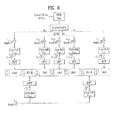
- FIG. 8 illustrates a CQI channel structure for a normal CP.
- SC-FDMA symbols #1 and #5 (second and sixth symbols) from among SC-FDMA symbols #0 to #6 of a slot may be used to transmit a demodulation reference signal (DMRS), and CQI information may be transmitted in the remaining SC-FDMA symbols.
- DMRS demodulation reference signal
- SC-FDMA symbol #3 one SC-FDMA symbol (SC-FDMA symbol #3) is used to transmit the DMRS.
- PUCCH formats 2/2a/2b modulation by a CAZAC sequence is supported, and a symbol modulated according to QPSK is multiplied by a CAZAC sequence with a length of 12.
- the CS of the sequence is changed between symbols and between slots.
- OC is used for the DMRS.
- SC-FDMA symbols Of the seven SC-FDMA symbols included in a slot, two SC-FDMA symbols spaced apart by an interval of three SC-FDMA symbols carry DMRSs and the remaining five SC-FDMA symbols carry CQI information. Two RSs are used in a slot in order to support a high-speed UE.
- a UE is identified using a CS sequence.
- CQI information symbols are modulated into SC-FDMA symbols and transmitted.
- An SC-FDMA symbol includes a sequence. That is, a UE modulates CQI into each sequence and transmits the sequences.
- the number of symbols that can be transmitted in a TTI is 10 and QPSK is determined for modulation of CQI information.
- QPSK mapping is employed for the SC-FDMA symbols
- an SC-FDMA symbol may carry a 2-bit CQI value and thus a slot may carry a 10-bit CQI value. Accordingly, a maximum of a 20-bit CQI value may be carried in a subframe.
- a frequency domain spreading code is used to spread the CQI information in the frequency domain.
- a CAZAC sequence with a length of 12 may be used for the frequency domain spreading code.
- Control channels may be distinguished from each other using CAZAC sequences having different CS values.
- the frequency-domain-spread CQI information is subjected to IFFT.
- 12 different UEs may be orthogonally multiplexed in the same PUCCH RB using 12 equally spaced CSs.
- a DMRS sequence on SC-FDMA symbols #1 and #5 (SC-FDMA symbols #3 for the extended CP) is similar to a CQI signal sequence in the frequency domain, but the DMRS sequence is not modulated as in the case of the CQI information.
- a UE may be semi-statically set by higher layer signaling so as to periodically report different CQI, PMI and RI types on a PUCCH resource indicated by a PUCCH resource index n PUCCH 2 .
- the PUCCH resource index N PUCCH 2 is information indicating a PUCCH region and a CS value used for PUCCH format 2/2a/2b transmission.
- the e-PUCCH format may correspond to PUCCH format 3 in LTE-A.
- Block spreading may be applied to ACK/NACK transmission using PUCCH format 3.
- Block spreading is a method of modulating a control signal using SC-FDMA, which is distinguished from the PUCCH format 1 or 2 series.
- a symbol sequence may be spread in the time domain using an orthogonal cover code (OCC) and transmitted.
- Control signals of a plurality UEs may be multiplexed in the same RB using the OCC.
- OCC orthogonal cover code
- a symbol sequence is transmitted in the time domain and control signals of multiple UEs are multiplexed using a CS of a CAZAC sequence.
- a symbol sequence is transmitted in the frequency domain and control signals of multiple UEs are multiplexed through the time domain spreading based on an OCC.
- SC-FDMA symbols i.e., data portions
- SF spreading factor
- two RS symbols may be used in one slot.
- the PUCCH channel structure employing the block spreading scheme it may be possible to transmit extended control information compared to the case of existing PUCCH formats 1 and 2.
- content of an ACK/NACK to a plurality of data units may be identified by a combination of an ACK/NACK unit actually used for ACK/NACK transmission and one of QPSK-modulated symbols.
- an ACK/NACK unit carries 2-bit information and receives a maximum of two data units.
- a HARQ ACK/NACK for each of the received data units is represented by an ACK/NACK bit.
- a transmitter that has transmitted data may identify the ACK/NACK results as shown below in [Table 4].
- DTX Discontinuous Transmission
- n PUCCH , X 1 denotes an ACK/NACK unit actually used for ACK/NACK transmission.
- the ACK/NACK units may be represented as n PUCCH , 0 1 and n PUCCH , 1 1 .
- b(0), b(1) denote two bits transmitted by selected ACK/NACK units. Modulation symbols transmitted through ACK/NACK units are determined depending on bits of b(0) and b(1).
- the receiver when the receiver successfully receives and decodes two data units (as indicated by ACK, ACK in [Table 4]), the receiver transmits two bits (1, 1) using the ACK/NACK unit n PUCCH , 1 1 . If the receiver fails to decode (or detect) the first data unit (i.e., data unit 0 corresponding to HARQ-ACK(0)) of the two received data units and successfully decodes the second data unit (i.e. data unit 1 corresponding to HARQ-ACK(1)) (as indicated by NACK/DTX, ACK in [Table 4]), the receiver transmits two bits (0, 0) using the ACK/NACK unit n PUCCH , 1 1 .
- the first data unit i.e., data unit 0 corresponding to HARQ-ACK(0)
- the second data unit i.e. data unit 1 corresponding to HARQ-ACK(1)
- ACK/NACK information about a plurality of data units using one ACK/NACK unit by linking or mapping a combination of a selected ACK/NACK unit and actual bits of the transmitted ACK/NACK unit (i.e., a combination of selected n PUCCH , 0 1 or n PUCCH , 1 1 and b(0), b(1) in [Table 4]) to the content of actual ACK/NACK.
- ACK/NACK multiplexing for more than two data units may be readily implemented by extending the principle of the above-described ACK/NACK multiplexing.
- NACK and DTX may not be discriminated from each other when at least one ACK is present for each data unit (that is, NACK and DTX may be coupled as NACK/DTX as shown in [Table 4]). This is because all ACK/NACK states (i.e., ACK/NACK hypotheses) that may be generated when NACK and DTX are discriminated from each other cannot be represented by only combinations of ACK/NACK units and QPSK-modulated symbols.
- ACK/NACK unit corresponding to a data unit for a definite NACK may be reserved for transmission of a plurality of ACK/NACK signals.
- single carrier transmission with good cubic metric (CM) property or a good peak-to-average power ratio (PAPR), which affects performance of a power amplifier is maintained to effectively utilize the power amplifier of the UE. That is, single carrier characteristics of data to be transmitted may be maintained through DFT-precoding in the case of PUSCH transmission in the legacy LTE system. In the case of PUCCH transmission, single carrier characteristics may be maintained by carrying information on a sequence having single carrier characteristics. However, if DFT-precoded data is non-continuously assigned on a frequency axis, or if PUSCH and PUCCH are simultaneously transmitted, such single carrier characteristics are not maintained.
- CM cubic metric
- PAPR peak-to-average power ratio
- uplink control information (UCI) to be transmitted on a PUCCH may be piggybacked together with data over a PUSCH in order to maintain the single carrier characteristics.
- UCI (a CQI/PMI, an HARQ-ACK, an RI, etc.) is multiplexed into a PUSCH region in a subframe carrying a PUSCH.
- control information and data may be transmitted together by multiplexing UL-SCH data with the CQI/PMI before DFT-spreading.
- the UL-SCH data is rate-matched in consideration of CQI/PMI resources.
- the control information such as an HARQ ACK, an RI, etc. may be multiplexed into the PUSCH region by puncturing the UL-SCH data.
- the EPDCCH that may be transmitted in a legacy PDSCH region is under consideration as a solution to the lack of PDCCH capacity and inter-cell interference caused by Coordinated Multi-Point (CoMP), Multi-User Multiple Input Multiple Output (MU-MIMO), etc. in an LTE system beyond Release 11.
- CoMP Coordinated Multi-Point
- MU-MIMO Multi-User Multiple Input Multiple Output
- the EPDCCH allows for Demodulation Reference Signal (DMRS)-based channel estimation to achieve a precoding gain.
- DMRS Demodulation Reference Signal
- the localized EPDCCH transmission means that ECCEs used for one DCI transmission are contiguous in the frequency domain, and specific precoding may be used to achieve a beamforming gain.
- the localized EPDCCH transmission may be based on as many contiguous ECCEs as determined by an aggregation level.
- the distributed EPDCCH transmission means that one EPDCCH is transmitted in PRB pairs distributed in the frequency domain.
- the distributed EPDCCH transmission offers a frequency diversity gain.
- the distributed EPDCCH transmission may be based on an ECCE having 4 EREGs included in each distributed PRB pair.
- One or two EPDCCH PRB sets may be configured for a UE by higher-layer signaling and each EPDCCH PRB set may be used for one of the localized EPDCCH transmission and the distributed EPDCCH transmission.
- the UE may perform blind decoding in a similar manner to in the legacy LTE/LTE-A system. More specifically, the UE may attempt to decode (monitor) an EPDCCH candidate set for each aggregation level, with respect to DCI formats corresponding to a configured transmission mode.
- the EPDCCH candidate set to be monitored may be referred to as an EPDCCH UE-specific search space and this search space may be configured/set for each aggregation level.
- aggregation levels ⁇ 1, 2, 4, 8, 16, 32 ⁇ are available according to a subframe type, a CP length, and the amount of available resources in a PRB pair.
- the UE indexes REs included in a PRB pair set as EREGs and indexes these EREGs on an ECCE basis.
- the UE determines EPDCCH candidates that form a search space based on the indexed ECCEs and performs blind decoding on the determined EPDCCH candidates, thereby receiving control information.
- EREG and ECCE correspond to REG and CCE of the legacy LTE/LTE-A system, respectively.
- One PRB pair may include 16 EREGs.
- the UE may transmit an ACK/NACK for the EPDCCH on a PUCCH.
- the indexes of resources for ACK/NACK transmission that is, the indexes of PUCCH resources may be determined by the lowest of the indexes of ECCEs used for the EPDCCH transmission, similarly to [Equation 1], that is, according to the following [Equation 2].
- n PUCCH - ECCE 1 n ECCE + N PUCCH 1
- n PUCCH - ECCE 1 represents a PUCCH resource index
- n ECCE represents the lowest of the indexes of ECCEs used for EPDCCH transmission
- N PUCCH 1 (or N PUCCH - EPDCCH 1 ) represents the starting point of PUCCH resource indexes, indicated by higher-layer signaling.
- a PUCCH resource index is determined unconditionally by [Equation 2]
- resource collision may occur.
- the EPDCCH PRB sets may have the same lowest ECCE index.
- this problem may be solved by setting different PUCCH resource starting points for different users, setting different PUCCH resource starting points for all users amounts to reservation of a large number of PUCCH resources, which is inefficient.
- DCI from a plurality of users may be transmitted at the same ECCE position on an EPDCCH, as is the case with MU-MIMO.
- ARO HARQ-ACK Resource Offset
- the ARO enables collision between PUCCH resources to be avoided by shifting PUCCH resources, which are determined based on the lowest of the indexes of ECCEs of an EPDCCH and a PUCCH resource starting offset indicated by higher-layer signaling, by a predetermined degree.
- An ARO is indicated in 2 bits of DCI format 1A/1B/1D/1/2A/2/2B/2C/2D transmitted on an EPDCCH, as illustrated in [Table 5].
- [Table 5] ACK/NACK Resource offset field in DCI format 1A/1B/1D/1/2A/2/2B/2C/2D ⁇ ARO 0 0 1 -1 2 -2 3 2
- An eNB may select one of the ARO values listed in [Table 5] and indicate the selected ARO value to a specific UE in a DCI format, so that the specific UE may use the ARO value in determining PUCCH resources.
- the UE may detect the ARO field from its DCI format and transmit a reception response in PUCCH resources determined based on the ARO value.
- FIG. 11(a) illustrates UL-DL configurations used in TDD
- FIG. 11(b) illustrates a reception response in TDD UL-DL configuration 2.
- FIG. 11 in the case of TDD UL-DL configuration 2, subframes available as UL subframes are limited to subframes 2 and 7. Accordingly, reception responses for eight DL subframes (including special subframes) need to be transmitted in the two UL subframes (subframes 2 and 7).
- DL association set indexes are defined as illustrated in [Table 6] below.
- [Table 6] UL-DL configuration
- DL association set K includes elements ⁇ k 0 , k 1 , ⁇ k M-1 ⁇ in each UL subframe and M is a bundling window size, indicating the number of DL subframes for which DL association set k is supposed to carry reception responses.
- M is a bundling window size, indicating the number of DL subframes for which DL association set k is supposed to carry reception responses.
- a number written in the first row indicates how many subframes a DL subframe is earlier than a current UL subframe.
- subframe 2 carries reception responses for 8 th , 7 th , 4 th , and 6 th earlier subframes from subframe 2 (i.e., subframes 4, 5, 8, and 6 in the previous radio frame), as illustrated in FIG. 11(b) .
- each UL-DL configuration indicates the index of a subframe indicated by the number written in the first row.
- () means a subframe of a previous radio frame
- [] means a subframe of a current radio frame
- a number without a bracket means a subframe of a second earlier radio frame from a current radio frame.
- PUCCH resources for transmission of a reception response in TDD may be allocated according to [Equation 3].
- n PUCCH 1 p ⁇ 0 M - m - 1 ⁇ N c + m ⁇ N c + 1 + n CCE , m + N PUCCH 1
- N PUCCH 1 represents a value indicated by higher-layer signaling
- N c max 0 ⁇ N RB DL ⁇ N sc RB ⁇ c - 4 / 36 ⁇
- n CCE,m represents a first CCE used for PDCCH transmission in subframe n-k m where k m is a smallest value for detecting a PDCCH in set k
- c is a value that the UE selects from ⁇ 0, 1, 2, 3 ⁇ to satisfy N c ⁇ n CCE ⁇ N c+1 .
- FIG. 12 illustrates an example of PUCCH resource allocation based on the above equation.
- resources are allocated for transmission of reception responses for three DL subframes (1 st s.f., 2 nd s.f., and 3 rd s.f.) and three CCE groups (CCE groups 1, 2, and 3 each including about one OFDM symbol) exist.
- CCE groups 1, 2, and 3 each including about one OFDM symbol
- to allocate PUCCH resources for each DL subframe in a UL subframe PUCCH resources for the three DL subframes are sequentially allocated/stacked/packed from CCE group 1. Then, PUCCH resources are allocated in the same manner from CCE group 2 and CCE group 3. Therefore, different PUCCH resources are allocated for different DL subframes despite the same CCE index, thereby avoiding collision. Further, since PDCCHs having the same CCE index are not transmitted in one DL subframe to different UEs, collision does not occur.
- PUCCH resources for a j th EPDCCH-PRB set of an m th subframe may be determined by [Equation 4].
- PUCCH resources are sequentially concatenated for each EPDCCH PRB set according to the sequence of an association set in order to transmit reception responses for a plurality of DL subframes in one UL subframe.
- a PUCCH resource region is reserved in subframe 2, for subframes corresponding to an association set ⁇ 13, 12, 9, 8, 7, 5, 4, 11, 6 ⁇ .
- FIG. 12 illustrates this example.
- each block represents a PUCCH resource region for each of subframes corresponding to the association set
- each subframe (except a special subframe configured for UL-DL switching) is pre-configured as a UL subframe or a DL subframe.
- UL-DL configuration specifically in UL-DL configuration 0, subframes 0 and 5 are pre-configured as DL subframes and subframes 2, 3, 4, 7, 8, and 9 are pre-configured as UL subframes in one radio frame.
- a UL-DL configuration that a specific eNB will use may be indicated to a UE by part of system information (e.g., SIB 1).
- Adjacent eNBs may be forced to use the same TDD configuration, that is, the same UL-DL configuration due to interference or the like.
- one or more UL subframes may be used/switched as/to DL subframes or one or more DL subframes may be used/switched as/to UL subframes, for reliable transmission of the data, thereby increasing efficiency.
- shaded UL subframes may be switched to DL subframes.
- [Table 8] is for the case where a switching periodicity is allowed to be changed. If a switching periodicity is not allowed to be changed, UL subframes that may be switched to DL subframes are shaded in [Table 9].
- UL subframes may be switched to DL subframes only when a legacy TDD configuration is satisfied.
- a TDD UL-DL configuration after the subframe usage change should be one of the UL-DL configurations listed in [Table 7].
- subframe 4 is switched to a DL subframe in UL-DL configuration
- subframe 9 should also be switched to a DL subframe at the same time. This case is advantageous in that it may be indicated in 1 bit whether a UL-DL configuration has been changed.
- one of legacy TDD UL-DL configurations may be used as an HARQ timeline. That is, it may be referred to as an HARQ (reference) timeline (a DL reference HARQ timeline or a DL reference UL/DL configuration, hereinafter referred to as a DL reference HARQ timeline) in a system having a subframe whose resources are dynamically changed.
- the HARQ reference timeline may be a TDD configuration for an HARQ timing that is used irrespective of a dynamic resource change, or a current TDD configuration in a situation in which resources have been changed dynamically.
- the following timelines may be configured for a UE: i) an HARQ timeline for a UL-DL configuration indicated by an SIB, ii) a DL reference HARQ timeline as to a time when an HARQ-ACK for a PDSCH/PDCCH for SPS release received at a specific time point is to be transmitted (for CA of different TDD configurations, the DL reference HARQ timeline is defined. This is done to effectively transmit HARQ-ACKs for two CCs by setting an HARQ timeline for transmitting a common reception response for the two CCs. A similar feature may also be used for a system in which the usage of resources is dynamically changed.
- an HARQ ACK may be stably transmitted even in a system in which the usage of a subframe is dynamically changed by setting an HARQ timeline for a relative static UL subframe), iii) a UL reference HARQ timeline as to when to transmit a PUSCH for a UL grant received at a specific time point and when to receive a PHICH for a PUSCH transmitted at a specific time point (for stable PHICH (PUSCH A/N) transmission and reception, the UL reference HARQ timeline may be configured for a TDD configuration having most UL subframes), and iv) an independent HARQ timeline for each DL subframe configured by separate signaling (a time delay occurs between signaling of a dynamic resource usage change by a higher-layer signal and an actual usage change.
- a specific SubFrame (SF) within the time delay may experience ambiguity in relation to an HARQ timeline.
- Such an exceptional SF is a separately indicated subframe other than the afore-described HARQ timeline, for transmission of an HARQ ACK. This operation is not likely to be indicated to every UE. If there is any UE to which the operation is not indicated, a PUCCH resource allocation scheme should be determined for the UE).
- All UEs within a cell may follow the same SIB-based timeline, ii) UEs having a first property (e.g., UEs having no eIMTA capability or legacy UEs (hereinafter, referred to as LUEs) may follow the SIB-based timeline and UEs having a second property (e.g., UEs having an eIMTA capability or advanced UEs (hereinafter, referred to as AUEs) may follow a newly defined HARQ timeline, and iii) all UEs may follow the newly defined HARQ timeline other than the SIB-based timeline.
- LUEs having no UEs having no eIMTA capability or legacy UEs hereinafter, referred to as LUEs
- UEs having a second property e.g., UEs having an eIMTA capability or advanced UEs (hereinafter, referred to as AUEs)
- AUEs advanced UEs
- all UEs may follow the newly defined HARQ
- the LUE and the AUE use different HARQ timelines as in the above example, collision may occur.
- the LUE and the AUE should transmit reception responses for different DL subframes in UL subframe 2 (the LUE should transmit reception responses for DL subframes 5 and 6 and the AUE should transmit reception responses for DL subframes 4, 5, 8, and 6).
- a UE receives a DL signal in subframe n in a TDD system, the UE should transmit a reception response for the DL signal in a k th subframe from the DL subframe.
- resources for reception responses in the k th subframe may be allocated/stacked/packed to/for a subframe common between a first timeline (a timeline for the LUE, which may be indicated by SIB 1) and a second timeline (a timeline for the AUE).
- the resources for reception responses in the k th subframe are allocated with priority to a subframe(s) of a first group, common between DL subframes for which reception responses should be transmitted in the k th subframe according to the first timeline and DL subframes for which reception responses should be transmitted in the k th subframe according to the second timeline.
- PUCCH resources may be allocated with priority for DL subframe 6 common between DL subframe 6 for which a reception response should be transmitted in UL subframe 2 according to the first timeline and DL subframes 4, 5, 8, and 6 for which reception responses should be transmitted in UL subframe 2 according to the second timeline.
- PUCCH resources are allocated with priority for a common DL subframe, DL subframe 6.
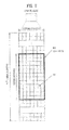
- FIG. 15(a) illustrates a case of receiving a DL signal by a PDCCH and FIG.
- the remaining resources may be allocated to a subframe(s) of a second group, except for the common subframe(s) among the subframes for which reception responses should be transmitted in the UL subframe.
- the resources allocated to the subframe(s) of the second group may be contiguous to or start apart from the resources allocated to the subframe(s) of the first group by a predetermined offset.
- the resources allocated to the subframe(s) of the second group may be included in resources for a PUCCH format different from a PUCCH format carrying reception responses for the subframe(s) of the first group.
- the resources allocated to the subframe(s) of the second group may (always) be transmitted in PUCCH format 3.
- the subframe(s) of the second group may be further classified and resources may be allocated sequentially to the subframe(s) of the second group according to the properties (fixed/static or flexible) of the DL subframes.
- a fixed/static subframe may be one of a DL subframe and a special subframe, when the first timeline is followed. Or the fixed/static subframe may be interpreted as a subframe for which an ACK/NACK is not transmitted in a corresponding UL subframe, unlike a DL HARQ timeline of an AUE.
- a flexible subframe may be a subframe that is not indicated as a DL subframe or a special subframe even in the first timeline.
- a subframe has a larger flexibility, this means that the subframe has a larger subframe index among contiguous UL subframes.
- the PUCCH resources may be sequentially allocated to flexible subframes.
- PUCCH resources may be allocated to a less flexible subframe with higher priority than a more flexible subframe among the flexible subframes.
- PUCCH resources for subframes having the same property and configured by a PDCCH may be interleaved on an OFDM symbol basis.
- resources for reception responses may be allocated first to DL subframe 6 common between the first and second time lines and then to the remaining DL subframes 4, 5, and 8.
- PUCCH resources may be allocated first to a fixed/static subframe, subframe 5 and then to flexible subframes, DL subframes 4 and 8.
- PUCCH resources for subframes configured by a PDCCH may be interleaved as illustrated in FIG. 15(a) .
- Embodiment 1 may be understood as indicating PUCCH resource positions by using implicit PUCCH resource mapping (CCE/ECCE indexes) for a DL subframe common to an LUE from among DL subframes of an AUE within a bundling window and allocating explicit PUCCH resources (PUCCH resources in an area indicated by a higher-layer signal: this may mean use of PUCCH format 3 or a case in which an additional PUCCH resource starting offset is assigned, in addition to a common PUCCH resource starting offset between the AUE and the LUE by a higher-layer signal) for a DL subframe that carries a PDCCH scheduling a PDSCH only for the AUE or a PDCCH for SPS release (i.e. a DL subframe not common to the LUE).
- CCE/ECCE indexes implicit PUCCH resource mapping
- PUCCH resources may be allocated as follows.
- the LUE packs PUCCH resources in a conventional manner.
- the AUE packs PUCCH resources by concatenating the PUCCH resources for a DL subframe monitored only by the AUE after the packing window of the LUE.
- PUCCH resources for the flexible subframe are preferably packed after a PUCCH region for the fixed DL subframe.
- a subframe having a large subframe index is flexible among flexible subframes (because in the presence of contiguous UL subframes, only an earlier UL subframe cannot be changed to a DL subframe: UUU ⁇ UUD possible and UUU ⁇ DUU impossible), the subframe having the large flexibility is relegated to a lower priority, when PUCCH resources are packed.
- PUCCH resources for subframes having the same property (flexible or static) and configured by a PDCCH may be interleaved on an OFDM symbol basis. However, this may be limited to the PDCCH.
- packing may be performed with priority on a PDCCH symbol basis for fixed or flexible DL subframes together from among subframes packed only by the AUE.
- collision between PUCCH resources of an AUE and an LUE may be prevented and a PUCCH region may be reduced by relegating a flexible subframe to a lower priority, when the flexible subframe is not monitored.
- only a part (a specific subset) may be selectively applied to the AUE.
- different rules may be applied to the PDCCH and the EPDCCH. For example, only i) may be applied to the AUE in the above description.
- use of a UL subframe as a DL subframe is indicated by a Downlink Allocation Index (DAI) and the LUE allocates PUCCH resources on the assumption that the same number of DL subframes as for the AUE are allocated. More specifically, an eNB allocates a DAI in a PDCCH/EPDCCH scheduled for the LUE based on the same TDD UL-DL configuration as for the AUE. In this case, the LUE determines the usage-changed subframe to be a missing subframe and both the LUE and the AUE use the same UL-DL configuration in allocating PUCCH resources.
- DAI Downlink Allocation Index
- both the LUE and the AUE perform an HARQ operation in the second timeline, thus partially avoiding collision between PUCCH resources.
- the LUE applies a channel selection table based on the second timeline in PUCCH format 1b with channel selection in this method.
- a shortcoming with the method is that the LUE may perform an unnecessary DTX operation, or use PUCCH format 3 or A/N bundling even though the number of DL subframes linked to one UL subframe does not actually exceed 4.
- the LUE and the AUE use the same A/N table with M set to 4 in UL subframe 2 in the example of [Table 12]
- the LUE may not use shaded parts of [Table 13] by always processing DL subframes 4 and 8 as DTX.
- different PUCCH starting offsets are assigned to the AUE and the LUE, for PUCCH resource allocation.
- the PUCCH starting offsets may be indicated by higher-layer signaling.
- a fourth embodiment is about a case in which a DL subframe for which the LUE should transmit a reception response in a specific UL subframe is a subset contiguous to a DL subframe for which the AUE should transmit a reception response in the specific UL subframe.
- the same PUCCH starting offset may be allocated to the AUE and the LUE.
- the AUE may calculate a CCE index based on the difference and apply an additional PUCCH resource stacking offset.
- the offset may be the number of CCEs/ECCEs included in additional DL subframes allocated to the AUE and the usage change indication indicated by the higher-layer signaling may be used as an indicator indicating the offset.
- a UE may determine a PUCCH starting position by subtracting the number of CCEs included in DL subframe 4 (when DL subframe 4 is scheduled by a PDCCH) or the number of ECCEs included in DL subframe 4 (when DL subframe 4 is scheduled by an EPDCCH) from N PUCCH 1 (a PUCCH resource starting offset).
- a new PUCCH resource starting position set for the AUE may be determined by calculating N PUCCH 1 - N CCE / ECCE ⁇ ⁇ S SF_Usage_change
- N CCE / ECCE is the number of CCEs/ECCEs included in a new DL subframe allocated to the AUE
- S SF_Usage_change indicates the presence or absence of a signaling indicating subframes usage change
- ⁇ ( x ) is a delta function that is 1 when x is 1.
- Embodiment 1-4 is basically identical to Embodiment 1-3 in that PUCCH resource collision is avoided by allocating different PUCCH resources to the LUE and the AUE but is advantageous in that even though the AUE fails to detect a subframe usage change indication, PUCCH resource collision can be avoided.
- the AUE may allocate resources for reception responses by always performing A/N time bundling and thus matching to the number of DL subframes of the LUE and using a CCE/ECCE index of a DL subframe overlapped with a DL subframe of the LUE from among the DL subframes of the AUE.
- a PUCCH resource index may be determined based on a DL subframe of the LUE.
- Time bundling may be a logical AND operation.
- the AUE may bundle reception responses for DL subframes 4 and 8 that are not overlapped with DL subframes 5 and 6 for which reception responses should be transmitted in UL subframe 2 according to the timeline of the LUE. That is, bundling may be performed on the reception responses for DL subframes 4 and 5 and reception responses for DL subframes 6 and 8.
- the bundled value of DL subframes 4 and 5 may be allocated to a CCE/ECCE index position of subframe 5 and the bundled value of DL subframes 6 and 8 may be allocated to a CCE/ECCE index position of subframe 6.
- PUCCH format 3 may be allocated to the LUE (or the AUE), whereas PUCCH format 1/2/1 a/1b/2a/2b may be allocated to the AUE (or the LUE). Or only different starting offsets may be set for the AUE and the LUE in the same PUCCH format.
- the number of DL subframes linked to one UL subframe is interpreted as different for the AUE and the LUE and a DAI of a PDCCH/EPDCCH is also indicated only for a DL subframe allocated to each of the AUE and the LUE.
- Embodiment 1-1 to Embodiment 1-6 is used for a DL subframe allocated by a PDCCH and an ARO is applied in determining resources for a reception response for a PDSCH allocated by an EPDCCH. Even though different numbers of DL subframes are stacked, PUCCH resource collision may be avoided to a certain extent.
- the AUE places resources for a reception response for a subframe allocated as a flexible subframe after the packing window of the LUE.
- resources are allocated first for DL subframes for which reception response should be transmitted in a UL subframe according to the first timeline of the LUE and then for DL subframes for which reception response should be transmitted in the UL subframe according to the second timeline of the AUE.
- the AUE when the AUE allocates resources for reception responses related to DL subframes 4, 5, 8, and 6, the AUE may allocate the resources in the order of DL subframes 5, 6, 4, and 8.
- the same PUCCH resource starting offset may be (have been) configured for the AUE and the LUE.
- the AUE may place resources for a reception response for a subframe allocated as a flexible subframe before the packing window of the LUE. For example, referring to [Table 12] again, the AUE may allocate resources for reception responses in the order of DL subframes 4, 8, 5, and 6, whereas the LUE may allocate resources for reception responses in the order of DL subframes 5 and 6. In this case, the AUE has a PUCCH resource starting offset before the LUE by the number of CCEs/ECCEs of DL subframes 4 and 8.
- the AUE may pack resources for reception responses according to the timeline of the LUE, while emptying resources for reception responses for DL subframes which are indicated by the timeline of the LUE but are absent in the timeline of the AUE. Then, the AUE may place resources for reception responses for DL subframes only indicated by the timeline of the AUE after the bundling window of the LUE.
- the AUE packs resources for reception responses in the order of DL subframes 5, 6, and 1 and sets Null for DL subframe 6 absent in the timeline of the AUE.
- the AUE may pack resources for reception responses in UL subframe 2 in the order of ⁇ 5, Null, 1, 0, 4 ⁇ or ⁇ 5, Null, 1, 4, 0 ⁇ .
- Null means emptying as many resources as the number of CCEs/ECCEs of DL subframe 6. This allocation of resources for reception responses is illustrated in FIG. 16 .
- Embodiment 1-10 may bring about resource waste by setting Null. Therefore, the indexes of DL subframes may be exchanged, instead.
- the index exchange may be performed so that the bundling window of the AUE is as close to that of the LUE as possible. After the index exchange, the number of DL subframes may become 4 or smaller. DL subframes present only in the timeline of the AUE may be placed after (or before) the bundling window of the LUE.
- the AUE since the AUE transmits a reception response for DL subframe 6 in UL subframe 3, the AUE may exchange (the index 7 of) DL subframe 6 for which a reception response should be transmitted in UL subframe 3 with (the index 8 of) DL subframe 4 for which a reception response should be transmitted in UL subframe 2.
- the AUE packs resources in the order of DL subframes ⁇ 5, 6, 1, 0 ⁇ in UL subframe 2 and in the order of DL subframes ⁇ 7, 8, 9, 4 ⁇ in UL subframe 3.
- the AUE matches its packing order to the subframe packing order of the LUE. If the LUE determines a packing order by selecting one of TDD configurations indicated by an SIB, the AUE may arrange subframes in the packing order selected by the LUE and then place the remaining subframes after the arranged subframes, rather than the AUE selects a packing order sequentially from a reference TDD configuration.
- the TDD UL/DL switching periodicity is 5ms or 10ms depending on whether the number of special subframes is 1 or 2 within 10ms.
- the LUE uses one of TDD configurations with a UL/DL switching periodicity of 5ms. If the AUE uses one of TDD configurations with a UL/DL switching periodicity of 10ms, subframes 5, 6, 7 for the LUE are D, S, U in this order. If the AUE uses D-S-U as D-D-D, the AUE and the LUE may pack subframes in different orders because in the case of D-S-U, the LUE places a special subframe at the end of packing but the AUE determines all of the subframes to be DL subframes.
- a DL reference HARQ timeline may be configured.
- TDD UL-DL configuration 5 may be set as the DL reference HARQ timeline.
- PUCCH resources may be insufficient because only one UL subframe carries reception responses in UL-DL configuration 5.
- the DL reference HARQ timeline may be indicated to the AUE by a higher-layer signal or a physical-layer signal.
- a DL reference HARQ timeline and a UL reference HARQ timeline may be indicated separately.
- a UE may suffer from HARQ timeline ambiguity at a time point when the UE receives a reference HARQ timeline and applies it. The following embodiments may be applied to this case.
- the AUE may pack resources for the reception responses based on an actually used UL-DL configuration. If the UE is aware that it has missed a reconfiguration message, the UE may use another PUCCH format (e.g., PUCCH format 3, etc.).
- the UE may first pack DL subframes (or static subframes) common between DL subframes for which reception responses should be transmitted in a corresponding UL subframe according to a new timeline after reconfiguration and DL subframes for which reception responses should be transmitted in the corresponding UL subframe according to an old timeline before the reconfiguration, and then may pack resources for the remaining subframes with a lower priority.
- the UE may follow a preset UL-DL configuration (UL-DL configuration 5 or a UL-DL configuration indicated by an SIB) during an ambiguous period.
- the UE may use a set of ARO values other than an existing ARO value set used in TDD, for application to flexible subframes. Since the set of ARO values applied to the flexible subframes are configured by RRC signaling, the ARO set may be selected and used, when the UE receives a configuration change request.
- the UE may monitor only static DL subframes, while processing the remaining subframes as DTX.
- FIG. 17 illustrates an example of failure to detect a reconfiguration message.
- the UE may monitor only static DL subframes in radio frame #n+1. In this case, the UE may pack resources for only the monitored static DL subframes and may not pack resources for the remaining DL subframes or treat them as DTX, in radio frame #n+2.
- the UE may determine by a CRC or the like whether it has detected the DCI successfully. If the UE fails to detect a reconfiguration message, it may perform the following operation.
- the UE may decode a PDSCH only in a static DL subframe and transmit a reception response for the PDSCH. Herein, the UE may follow an SIB-based timeline or a DL reference HARQ timeline. Since the UE does not monitor a PDCCH in a flexible subframe, the UE may process corresponding PDSCHs as DTX. The UE may determine DTX or non-DTX even without monitoring a flexible subframe, according to a DAI setting of an eNB.
- the UE may not transmit any of reception responses (even reception responses for static DL subframes) related to a corresponding radio frame.
- the UE may decode PDSCHs only in subsets of static DL subframes packed before flexible subframes and transmit reception responses for the PDSCHs.
- the UE may use one of the afore-described methods.
- the UE fails to detect a reconfiguration message for a radio frame and thus does not transmit any of reception responses related to the radio frame
- the UE may not transmit any of reception responses in the UL subframe. This is because a packing order may be ambiguous and thus the UE drops all reception responses in the corresponding subframe.
- resources for a reception response to be transmitted repeatedly may be included only in a UL subframe of an available timeline having the smaller number of UL subframes between the first and second timelines. That is, if HARQ ACK repetition is triggered, a reception response repeated only in a static UL subframe is fed back. In this case, the number of repetitions may be counted only when a reception response is repeated in a static UL subframe. Also, bundling and repetition may be performed only on static DL subframes.
- Soft buffer partitioning based on the number of DL HARQ processes at a UE may be performed according to a maximum number of DL HARQ processes linked to a representative UL/DL HARQ timeline. For example, if the representative UL/DL HARQ timeline is defined as UL-DL configuration 3, a UE may divide a soft buffer into as many partitions as the number of DL HARQ processes of UL-DL configuration 3, that is, 9 partitions.
- an eNB may set a DAI field according to a DL reference TDD configuration in the above description. If a UE packs PUCCH resources according to a current reconfiguration message, the DAI field may be based on a TDD configuration of the reconfiguration message.
- the above descriptions are effective restrictively only when cross carrier scheduling and/or self-scheduling is used. Also, the above descriptions may be applied selectively only to UEs operating in eIMTA. Also, the above descriptions may be applied selectively only to a specific PUCCH format (e.g., PUCCH format 1a/1b/2/2a/2b).
- FIG. 18 is a block diagram of a transmission point and a UE according to an embodiment of the present invention.
- a transmission point 10 may include a reception module 11, a transmission module 12, a processor 13, a memory 14, and a plurality of antennas 15. Use of the plurality of antennas 15 means that the transmission point 10 supports MIMO transmission and reception.
- the reception module 11 may receive UL signals, data, and information from a UE.
- the transmission module 12 may transmit DL signals, data, and information to a UE.
- the processor 13 may provide overall control to the transmission point 10.
- the processor 13 of the transmission point 10 may perform necessary operations in the afore-described embodiments.
- the processor 13 of the transmission point 10 processes received information and information to be transmitted to the outside of the transmission point 10.
- the memory 14 may store the processed information for a predetermined time and may be replaced with a component such as a buffer (not shown).
- a UE 20 may include a reception module 21, a transmission module 22, a processor 23, a memory 24, and a plurality of antennas 25.
- Use of the plurality of antennas 25 means that the UE 20 supports MIMO transmission and reception using the plurality of antennas 25.
- the reception module 21 may receive DL signals, data, and information from an eNB.
- the transmission module 22 may transmit UL signals, data, and information to an eNB.
- the processor 23 may provide overall control to the UE 20.
- the processor 23 of the UE 20 may perform necessary operations in the afore-described embodiments.
- the processor 23 of the UE 20 processes received information and information to be transmitted to the outside of the UE 20.
- the memory 24 may store the processed information for a predetermined time and may be replaced with a component such as a buffer (not shown).
- the above transmission point and UE may be configured in such a manner that the above-described various embodiments of the present invention may be implemented independently or in combination of two or more. A redundant description is omitted for clarity.
- the description of the transmission point 10 in FIG. 18 is applicable to a relay as a DL transmitter or a UL receiver, and the description of the UE 20 in FIG. 14 is applicable to a relay as a DL receiver or a UL transmitter.
- the embodiments of the present invention may be implemented by various means, for example, in hardware, firmware, software, or a combination thereof.
- the method according to the embodiments of the present invention may be implemented by one or more Application Specific Integrated Circuits (ASICs), Digital Signal Processors (DSPs), Digital Signal Processing Devices (DSPDs), Programmable Logic Devices (PLDs), Field Programmable Gate Arrays (FPGAs), processors, controllers, microcontrollers, or microprocessors.
- ASICs Application Specific Integrated Circuits
- DSPs Digital Signal Processors
- DSPDs Digital Signal Processing Devices
- PLDs Programmable Logic Devices
- FPGAs Field Programmable Gate Arrays
- processors controllers, microcontrollers, or microprocessors.
- the method according to the embodiments of the present invention may be implemented in the form of modules, procedures, functions, etc. performing the above-described functions or operations.
- Software code may be stored in a memory unit and executed by a processor.
- the memory unit may be located at the interior or exterior of the processor and may transmit and receive data to and from the processor via various known means.
Landscapes
- Engineering & Computer Science (AREA)
- Signal Processing (AREA)
- Computer Networks & Wireless Communication (AREA)
- Mobile Radio Communication Systems (AREA)
- Communication Control (AREA)
Applications Claiming Priority (5)
| Application Number | Priority Date | Filing Date | Title |
|---|---|---|---|
| US201361750801P | 2013-01-09 | 2013-01-09 | |
| US201361818922P | 2013-05-03 | 2013-05-03 | |
| US201361823930P | 2013-05-16 | 2013-05-16 | |
| US201361834886P | 2013-06-14 | 2013-06-14 | |
| PCT/KR2014/000258 WO2014109571A1 (ko) | 2013-01-09 | 2014-01-09 | 무선 통신 시스템에서 수신확인응답 전송 방법 및 장치 |
Publications (3)
| Publication Number | Publication Date |
|---|---|
| EP2945310A1 true EP2945310A1 (de) | 2015-11-18 |
| EP2945310A4 EP2945310A4 (de) | 2016-10-19 |
| EP2945310B1 EP2945310B1 (de) | 2021-09-01 |
Family
ID=51167155
Family Applications (1)
| Application Number | Title | Priority Date | Filing Date |
|---|---|---|---|
| EP14737613.1A Active EP2945310B1 (de) | 2013-01-09 | 2014-01-09 | Verfahren und vorrichtung zur übertragung von empfangsbestätigungen in einem drahtlosen kommunikationssystem |
Country Status (6)
| Country | Link |
|---|---|
| US (1) | US9882697B2 (de) |
| EP (1) | EP2945310B1 (de) |
| JP (3) | JP6006434B2 (de) |
| KR (1) | KR102197967B1 (de) |
| CN (1) | CN104995859B (de) |
| WO (1) | WO2014109571A1 (de) |
Cited By (2)
| Publication number | Priority date | Publication date | Assignee | Title |
|---|---|---|---|---|
| CN109246042A (zh) * | 2017-08-25 | 2019-01-18 | 华为技术有限公司 | 一种信号传输的方法、设备及系统 |
| CN115913479A (zh) * | 2021-08-09 | 2023-04-04 | 展讯通信(上海)有限公司 | 资源碰撞指示方法及装置、终端设备 |
Families Citing this family (20)
| Publication number | Priority date | Publication date | Assignee | Title |
|---|---|---|---|---|
| US9191930B2 (en) | 2013-03-13 | 2015-11-17 | Samsung Electronics Co., Ltd. | Transmission of acknowledgement information in adaptively configured TDD communication systems |
| US9565593B2 (en) | 2013-05-20 | 2017-02-07 | Qualcomm Incorporated | Techniques for selecting subframe type or for interleaving signals for wireless communications over unlicensed spectrum |
| WO2015005678A1 (ko) * | 2013-07-09 | 2015-01-15 | 엘지전자 주식회사 | 무선 자원의 용도 변경을 지원하는 무선 통신 시스템에서 채널 상태 측정 방법 및 이를 위한 장치 |
| JP6629745B2 (ja) * | 2014-02-18 | 2020-01-15 | エルジー エレクトロニクス インコーポレイティド | 無線リソースの用途変更を支援する無線通信システムにおけるチャネル状態情報報告方法及びそのための装置 |
| KR101857667B1 (ko) * | 2014-03-12 | 2018-06-19 | 엘지전자 주식회사 | 무선 자원의 용도 변경을 지원하는 무선 통신 시스템에서 상향링크 제어 채널 송신 방법 및 이를 위한 장치 |
| WO2016165131A1 (zh) * | 2015-04-17 | 2016-10-20 | 华为技术有限公司 | 一种信息反馈的方法、设备和系统 |
| CN106559887B (zh) * | 2015-09-29 | 2021-12-31 | 华为技术有限公司 | 配置资源的方法及网络设备 |
| US10680699B2 (en) * | 2016-07-20 | 2020-06-09 | Lg Electronics Inc. | Method and apparatus for calculating beamforming based paging occasion in wireless communication system |
| WO2018021824A1 (ko) * | 2016-07-26 | 2018-02-01 | 엘지전자 주식회사 | 상향링크 신호 전송 방법 및 사용자기기와, 상향링크 신호 수신 방법 및 기지국 |
| JP7163277B2 (ja) * | 2016-08-21 | 2022-10-31 | エルジー エレクトロニクス インコーポレイティド | 無線通信システムにおいて上りリンク送信のための方法及びそのための装置 |
| CN107889230B (zh) * | 2016-09-29 | 2022-11-29 | 中兴通讯股份有限公司 | 信号发送、接收发送及装置 |
| ES2813589T3 (es) * | 2016-10-28 | 2021-03-24 | Asustek Comp Inc | Procedimiento y aparato para mejorar la retroalimentación de harq en un tti abreviado en un sistema de comunicación inalámbrica |
| KR20180068677A (ko) * | 2016-12-14 | 2018-06-22 | 삼성전자주식회사 | 무선 통신 시스템에서 하향링크 제어채널의 송수신 방법 및 장치 |
| EP3586460B1 (de) * | 2017-03-17 | 2021-09-22 | Huawei Technologies Duesseldorf GmbH | Verfahren zur latenzbewussten verarbeitung von funkrahmen |
| EP3602903B1 (de) * | 2017-03-24 | 2022-09-07 | Telefonaktiebolaget LM Ericsson (publ) | Technik zur steuerung des timings von uplink-steuerungsinformationen in einer funkkommunikation zwischen einem netzwerkknoten und einer funkvorrichtung |
| US11445483B2 (en) * | 2017-08-01 | 2022-09-13 | Qualcomm Incorporated | Uplink control channel resource definition and mapping to user equipment |
| MY207842A (en) * | 2018-01-12 | 2025-03-21 | Panasonic Ip Corp America | Base station, terminal, and communication method |
| WO2021185229A1 (zh) * | 2020-03-20 | 2021-09-23 | 上海朗帛通信技术有限公司 | 一种被用于无线通信的节点中的方法和装置 |
| WO2022028921A1 (en) * | 2020-08-06 | 2022-02-10 | Nokia Technologies Oy | Reconfiguration messages during multi-connectivity in wireless communication |
| KR20220113025A (ko) * | 2021-02-05 | 2022-08-12 | 삼성전자주식회사 | 무선 통신 시스템에서 스케줄링을 수행하기 위한 방법 및 장치 |
Family Cites Families (9)
| Publication number | Priority date | Publication date | Assignee | Title |
|---|---|---|---|---|
| KR100905385B1 (ko) | 2008-03-16 | 2009-06-30 | 엘지전자 주식회사 | 무선통신 시스템에서 제어신호의 효율적인 전송방법 |
| JP5721443B2 (ja) | 2008-03-16 | 2015-05-20 | エルジー エレクトロニクス インコーポレイティド | 無線通信システムにおけるharq実行方法 |
| EP2553857A4 (de) * | 2010-03-31 | 2014-05-28 | Samsung Electronics Co Ltd | Indizierung von ressourcen zur übertragung von bestätigungssignalen in mehrzellen-tdd-kommunikationssystemen |
| WO2012106840A1 (en) * | 2011-02-10 | 2012-08-16 | Renesas Mobile Corporation | Resource allocation for flexible tdd configuration |
| WO2012113131A1 (en) * | 2011-02-21 | 2012-08-30 | Renesas Mobile Corporation | Dynamic uplink/downlink configuration for time division duplex |
| US9363820B2 (en) * | 2011-08-11 | 2016-06-07 | Industrial Technology Research Institute | Method of uplink control information transmission |
| DK2742756T3 (en) * | 2011-08-12 | 2015-03-09 | Ericsson Telefon Ab L M | BASIC STATION, USER EQUIPMENT AND METHODS OF TIME MANAGEMENT CONFIGURATION ALLOCATION IN A MULTIPLE CELL TELECOMMUNICATION NETWORK |
| US9185564B2 (en) * | 2012-05-11 | 2015-11-10 | Sharp Kabushiki Kaisha | Devices for sending and receiving feedback information |
| KR101800707B1 (ko) * | 2012-09-28 | 2017-11-23 | 인텔 코포레이션 | 강화된 물리 다운링크 제어 채널을 이용한 동적 복합 자동 반복 요청-긍정응답(harq-ack) 송신 |
-
2014
- 2014-01-09 WO PCT/KR2014/000258 patent/WO2014109571A1/ko not_active Ceased
- 2014-01-09 EP EP14737613.1A patent/EP2945310B1/de active Active
- 2014-01-09 US US14/759,355 patent/US9882697B2/en active Active
- 2014-01-09 JP JP2015552579A patent/JP6006434B2/ja not_active Expired - Fee Related
- 2014-01-09 KR KR1020157021483A patent/KR102197967B1/ko active Active
- 2014-01-09 CN CN201480004348.6A patent/CN104995859B/zh active Active
-
2016
- 2016-09-08 JP JP2016175427A patent/JP6224795B2/ja active Active
-
2017
- 2017-10-05 JP JP2017195141A patent/JP6408103B2/ja active Active
Cited By (4)
| Publication number | Priority date | Publication date | Assignee | Title |
|---|---|---|---|---|
| CN109246042A (zh) * | 2017-08-25 | 2019-01-18 | 华为技术有限公司 | 一种信号传输的方法、设备及系统 |
| US11095492B2 (en) | 2017-08-25 | 2021-08-17 | Huawei Technologies Co., Ltd. | Signal transmission method, device, and system |
| US12113659B2 (en) | 2017-08-25 | 2024-10-08 | Huawei Technologies Co., Ltd. | Signal transmission method, device, and system |
| CN115913479A (zh) * | 2021-08-09 | 2023-04-04 | 展讯通信(上海)有限公司 | 资源碰撞指示方法及装置、终端设备 |
Also Published As
| Publication number | Publication date |
|---|---|
| WO2014109571A1 (ko) | 2014-07-17 |
| JP2016510536A (ja) | 2016-04-07 |
| JP2018033153A (ja) | 2018-03-01 |
| KR20150136468A (ko) | 2015-12-07 |
| CN104995859A (zh) | 2015-10-21 |
| EP2945310B1 (de) | 2021-09-01 |
| KR102197967B1 (ko) | 2021-01-04 |
| JP6408103B2 (ja) | 2018-10-17 |
| US20150358137A1 (en) | 2015-12-10 |
| JP2017022749A (ja) | 2017-01-26 |
| CN104995859B (zh) | 2018-11-02 |
| JP6224795B2 (ja) | 2017-11-01 |
| US9882697B2 (en) | 2018-01-30 |
| JP6006434B2 (ja) | 2016-10-12 |
| EP2945310A4 (de) | 2016-10-19 |
Similar Documents
| Publication | Publication Date | Title |
|---|---|---|
| EP2945310B1 (de) | Verfahren und vorrichtung zur übertragung von empfangsbestätigungen in einem drahtlosen kommunikationssystem | |
| US10581562B2 (en) | Method and apparatus for transmitting HARQ-ACK in wireless communication system | |
| US9743395B2 (en) | Method for transceiving control signals, and apparatus therefor | |
| US9900870B2 (en) | Method and apparatus for transmitting receipt acknowledgement in wireless communication system | |
| US9717089B2 (en) | Method and apparatus for transmitting acknowledgement of reception in wireless communication system | |
| US9590786B2 (en) | Method and apparatus for transmitting acknowledgement in wireless communication system | |
| US10506567B2 (en) | Method and apparatus for transmitting and receiving uplink signal in wireless communication system | |
| US20170064683A1 (en) | Method for operating terminal in carrier aggregation system, and apparatus using said method | |
| US9750005B2 (en) | Method and apparatus for transmitting control information in wireless communication system |
Legal Events
| Date | Code | Title | Description |
|---|---|---|---|
| PUAI | Public reference made under article 153(3) epc to a published international application that has entered the european phase |
Free format text: ORIGINAL CODE: 0009012 |
|
| 17P | Request for examination filed |
Effective date: 20150629 |
|
| AK | Designated contracting states |
Kind code of ref document: A1 Designated state(s): AL AT BE BG CH CY CZ DE DK EE ES FI FR GB GR HR HU IE IS IT LI LT LU LV MC MK MT NL NO PL PT RO RS SE SI SK SM TR |
|
| AX | Request for extension of the european patent |
Extension state: BA ME |
|
| DAX | Request for extension of the european patent (deleted) | ||
| A4 | Supplementary search report drawn up and despatched |
Effective date: 20160916 |
|
| RIC1 | Information provided on ipc code assigned before grant |
Ipc: H04L 1/16 20060101AFI20160912BHEP |
|
| STAA | Information on the status of an ep patent application or granted ep patent |
Free format text: STATUS: EXAMINATION IS IN PROGRESS |
|
| 17Q | First examination report despatched |
Effective date: 20190930 |
|
| GRAP | Despatch of communication of intention to grant a patent |
Free format text: ORIGINAL CODE: EPIDOSNIGR1 |
|
| STAA | Information on the status of an ep patent application or granted ep patent |
Free format text: STATUS: GRANT OF PATENT IS INTENDED |
|
| INTG | Intention to grant announced |
Effective date: 20210401 |
|
| GRAS | Grant fee paid |
Free format text: ORIGINAL CODE: EPIDOSNIGR3 |
|
| GRAA | (expected) grant |
Free format text: ORIGINAL CODE: 0009210 |
|
| STAA | Information on the status of an ep patent application or granted ep patent |
Free format text: STATUS: THE PATENT HAS BEEN GRANTED |
|
| AK | Designated contracting states |
Kind code of ref document: B1 Designated state(s): AL AT BE BG CH CY CZ DE DK EE ES FI FR GB GR HR HU IE IS IT LI LT LU LV MC MK MT NL NO PL PT RO RS SE SI SK SM TR |
|
| REG | Reference to a national code |
Ref country code: GB Ref legal event code: FG4D |
|
| REG | Reference to a national code |
Ref country code: CH Ref legal event code: EP Ref country code: AT Ref legal event code: REF Ref document number: 1427345 Country of ref document: AT Kind code of ref document: T Effective date: 20210915 |
|
| REG | Reference to a national code |
Ref country code: DE Ref legal event code: R096 Ref document number: 602014079822 Country of ref document: DE |
|
| REG | Reference to a national code |
Ref country code: IE Ref legal event code: FG4D |
|
| REG | Reference to a national code |
Ref country code: LT Ref legal event code: MG9D |
|
| REG | Reference to a national code |
Ref country code: NL Ref legal event code: MP Effective date: 20210901 |
|
| PG25 | Lapsed in a contracting state [announced via postgrant information from national office to epo] |
Ref country code: LT Free format text: LAPSE BECAUSE OF FAILURE TO SUBMIT A TRANSLATION OF THE DESCRIPTION OR TO PAY THE FEE WITHIN THE PRESCRIBED TIME-LIMIT Effective date: 20210901 Ref country code: BG Free format text: LAPSE BECAUSE OF FAILURE TO SUBMIT A TRANSLATION OF THE DESCRIPTION OR TO PAY THE FEE WITHIN THE PRESCRIBED TIME-LIMIT Effective date: 20211201 Ref country code: NO Free format text: LAPSE BECAUSE OF FAILURE TO SUBMIT A TRANSLATION OF THE DESCRIPTION OR TO PAY THE FEE WITHIN THE PRESCRIBED TIME-LIMIT Effective date: 20211201 Ref country code: FI Free format text: LAPSE BECAUSE OF FAILURE TO SUBMIT A TRANSLATION OF THE DESCRIPTION OR TO PAY THE FEE WITHIN THE PRESCRIBED TIME-LIMIT Effective date: 20210901 Ref country code: ES Free format text: LAPSE BECAUSE OF FAILURE TO SUBMIT A TRANSLATION OF THE DESCRIPTION OR TO PAY THE FEE WITHIN THE PRESCRIBED TIME-LIMIT Effective date: 20210901 Ref country code: HR Free format text: LAPSE BECAUSE OF FAILURE TO SUBMIT A TRANSLATION OF THE DESCRIPTION OR TO PAY THE FEE WITHIN THE PRESCRIBED TIME-LIMIT Effective date: 20210901 Ref country code: RS Free format text: LAPSE BECAUSE OF FAILURE TO SUBMIT A TRANSLATION OF THE DESCRIPTION OR TO PAY THE FEE WITHIN THE PRESCRIBED TIME-LIMIT Effective date: 20210901 Ref country code: SE Free format text: LAPSE BECAUSE OF FAILURE TO SUBMIT A TRANSLATION OF THE DESCRIPTION OR TO PAY THE FEE WITHIN THE PRESCRIBED TIME-LIMIT Effective date: 20210901 |
|
| REG | Reference to a national code |
Ref country code: AT Ref legal event code: MK05 Ref document number: 1427345 Country of ref document: AT Kind code of ref document: T Effective date: 20210901 |
|
| PG25 | Lapsed in a contracting state [announced via postgrant information from national office to epo] |
Ref country code: PL Free format text: LAPSE BECAUSE OF FAILURE TO SUBMIT A TRANSLATION OF THE DESCRIPTION OR TO PAY THE FEE WITHIN THE PRESCRIBED TIME-LIMIT Effective date: 20210901 Ref country code: LV Free format text: LAPSE BECAUSE OF FAILURE TO SUBMIT A TRANSLATION OF THE DESCRIPTION OR TO PAY THE FEE WITHIN THE PRESCRIBED TIME-LIMIT Effective date: 20210901 Ref country code: GR Free format text: LAPSE BECAUSE OF FAILURE TO SUBMIT A TRANSLATION OF THE DESCRIPTION OR TO PAY THE FEE WITHIN THE PRESCRIBED TIME-LIMIT Effective date: 20211202 |
|
| PG25 | Lapsed in a contracting state [announced via postgrant information from national office to epo] |
Ref country code: AT Free format text: LAPSE BECAUSE OF FAILURE TO SUBMIT A TRANSLATION OF THE DESCRIPTION OR TO PAY THE FEE WITHIN THE PRESCRIBED TIME-LIMIT Effective date: 20210901 |
|
| PG25 | Lapsed in a contracting state [announced via postgrant information from national office to epo] |
Ref country code: IS Free format text: LAPSE BECAUSE OF FAILURE TO SUBMIT A TRANSLATION OF THE DESCRIPTION OR TO PAY THE FEE WITHIN THE PRESCRIBED TIME-LIMIT Effective date: 20220101 Ref country code: SM Free format text: LAPSE BECAUSE OF FAILURE TO SUBMIT A TRANSLATION OF THE DESCRIPTION OR TO PAY THE FEE WITHIN THE PRESCRIBED TIME-LIMIT Effective date: 20210901 Ref country code: SK Free format text: LAPSE BECAUSE OF FAILURE TO SUBMIT A TRANSLATION OF THE DESCRIPTION OR TO PAY THE FEE WITHIN THE PRESCRIBED TIME-LIMIT Effective date: 20210901 Ref country code: RO Free format text: LAPSE BECAUSE OF FAILURE TO SUBMIT A TRANSLATION OF THE DESCRIPTION OR TO PAY THE FEE WITHIN THE PRESCRIBED TIME-LIMIT Effective date: 20210901 Ref country code: PT Free format text: LAPSE BECAUSE OF FAILURE TO SUBMIT A TRANSLATION OF THE DESCRIPTION OR TO PAY THE FEE WITHIN THE PRESCRIBED TIME-LIMIT Effective date: 20220103 Ref country code: NL Free format text: LAPSE BECAUSE OF FAILURE TO SUBMIT A TRANSLATION OF THE DESCRIPTION OR TO PAY THE FEE WITHIN THE PRESCRIBED TIME-LIMIT Effective date: 20210901 Ref country code: EE Free format text: LAPSE BECAUSE OF FAILURE TO SUBMIT A TRANSLATION OF THE DESCRIPTION OR TO PAY THE FEE WITHIN THE PRESCRIBED TIME-LIMIT Effective date: 20210901 Ref country code: CZ Free format text: LAPSE BECAUSE OF FAILURE TO SUBMIT A TRANSLATION OF THE DESCRIPTION OR TO PAY THE FEE WITHIN THE PRESCRIBED TIME-LIMIT Effective date: 20210901 Ref country code: AL Free format text: LAPSE BECAUSE OF FAILURE TO SUBMIT A TRANSLATION OF THE DESCRIPTION OR TO PAY THE FEE WITHIN THE PRESCRIBED TIME-LIMIT Effective date: 20210901 |
|
| REG | Reference to a national code |
Ref country code: DE Ref legal event code: R097 Ref document number: 602014079822 Country of ref document: DE |
|
| PLBE | No opposition filed within time limit |
Free format text: ORIGINAL CODE: 0009261 |
|
| STAA | Information on the status of an ep patent application or granted ep patent |
Free format text: STATUS: NO OPPOSITION FILED WITHIN TIME LIMIT |
|
| PG25 | Lapsed in a contracting state [announced via postgrant information from national office to epo] |
Ref country code: IT Free format text: LAPSE BECAUSE OF FAILURE TO SUBMIT A TRANSLATION OF THE DESCRIPTION OR TO PAY THE FEE WITHIN THE PRESCRIBED TIME-LIMIT Effective date: 20210901 Ref country code: DK Free format text: LAPSE BECAUSE OF FAILURE TO SUBMIT A TRANSLATION OF THE DESCRIPTION OR TO PAY THE FEE WITHIN THE PRESCRIBED TIME-LIMIT Effective date: 20210901 |
|
| 26N | No opposition filed |
Effective date: 20220602 |
|
| PG25 | Lapsed in a contracting state [announced via postgrant information from national office to epo] |
Ref country code: SI Free format text: LAPSE BECAUSE OF FAILURE TO SUBMIT A TRANSLATION OF THE DESCRIPTION OR TO PAY THE FEE WITHIN THE PRESCRIBED TIME-LIMIT Effective date: 20210901 Ref country code: MC Free format text: LAPSE BECAUSE OF FAILURE TO SUBMIT A TRANSLATION OF THE DESCRIPTION OR TO PAY THE FEE WITHIN THE PRESCRIBED TIME-LIMIT Effective date: 20210901 |
|
| REG | Reference to a national code |
Ref country code: CH Ref legal event code: PL |
|
| GBPC | Gb: european patent ceased through non-payment of renewal fee |
Effective date: 20220109 |
|
| REG | Reference to a national code |
Ref country code: BE Ref legal event code: MM Effective date: 20220131 |
|
| PG25 | Lapsed in a contracting state [announced via postgrant information from national office to epo] |
Ref country code: LU Free format text: LAPSE BECAUSE OF NON-PAYMENT OF DUE FEES Effective date: 20220109 Ref country code: GB Free format text: LAPSE BECAUSE OF NON-PAYMENT OF DUE FEES Effective date: 20220109 |
|
| PG25 | Lapsed in a contracting state [announced via postgrant information from national office to epo] |
Ref country code: FR Free format text: LAPSE BECAUSE OF NON-PAYMENT OF DUE FEES Effective date: 20220131 Ref country code: BE Free format text: LAPSE BECAUSE OF NON-PAYMENT OF DUE FEES Effective date: 20220131 |
|
| PG25 | Lapsed in a contracting state [announced via postgrant information from national office to epo] |
Ref country code: LI Free format text: LAPSE BECAUSE OF NON-PAYMENT OF DUE FEES Effective date: 20220131 Ref country code: CH Free format text: LAPSE BECAUSE OF NON-PAYMENT OF DUE FEES Effective date: 20220131 |
|
| PG25 | Lapsed in a contracting state [announced via postgrant information from national office to epo] |
Ref country code: IE Free format text: LAPSE BECAUSE OF NON-PAYMENT OF DUE FEES Effective date: 20220109 |
|
| PG25 | Lapsed in a contracting state [announced via postgrant information from national office to epo] |
Ref country code: HU Free format text: LAPSE BECAUSE OF FAILURE TO SUBMIT A TRANSLATION OF THE DESCRIPTION OR TO PAY THE FEE WITHIN THE PRESCRIBED TIME-LIMIT; INVALID AB INITIO Effective date: 20140109 |
|
| PG25 | Lapsed in a contracting state [announced via postgrant information from national office to epo] |
Ref country code: MK Free format text: LAPSE BECAUSE OF FAILURE TO SUBMIT A TRANSLATION OF THE DESCRIPTION OR TO PAY THE FEE WITHIN THE PRESCRIBED TIME-LIMIT Effective date: 20210901 Ref country code: CY Free format text: LAPSE BECAUSE OF FAILURE TO SUBMIT A TRANSLATION OF THE DESCRIPTION OR TO PAY THE FEE WITHIN THE PRESCRIBED TIME-LIMIT Effective date: 20210901 |
|
| PG25 | Lapsed in a contracting state [announced via postgrant information from national office to epo] |
Ref country code: TR Free format text: LAPSE BECAUSE OF FAILURE TO SUBMIT A TRANSLATION OF THE DESCRIPTION OR TO PAY THE FEE WITHIN THE PRESCRIBED TIME-LIMIT Effective date: 20210901 |
|
| PG25 | Lapsed in a contracting state [announced via postgrant information from national office to epo] |
Ref country code: MT Free format text: LAPSE BECAUSE OF FAILURE TO SUBMIT A TRANSLATION OF THE DESCRIPTION OR TO PAY THE FEE WITHIN THE PRESCRIBED TIME-LIMIT Effective date: 20210901 |
|
| PGFP | Annual fee paid to national office [announced via postgrant information from national office to epo] |
Ref country code: DE Payment date: 20251208 Year of fee payment: 13 |