EP2945411B1 - Millimeterwellen-phasengesteuertes strahlenausrichtungsverfahren und kommunikationsvorrichtung - Google Patents
Millimeterwellen-phasengesteuertes strahlenausrichtungsverfahren und kommunikationsvorrichtung Download PDFInfo
- Publication number
- EP2945411B1 EP2945411B1 EP14743340.3A EP14743340A EP2945411B1 EP 2945411 B1 EP2945411 B1 EP 2945411B1 EP 14743340 A EP14743340 A EP 14743340A EP 2945411 B1 EP2945411 B1 EP 2945411B1
- Authority
- EP
- European Patent Office
- Prior art keywords
- millimeter wave
- wave signal
- signal
- receiving
- search
- Prior art date
- Legal status (The legal status is an assumption and is not a legal conclusion. Google has not performed a legal analysis and makes no representation as to the accuracy of the status listed.)
- Active
Links
Images






Classifications
-
- H—ELECTRICITY
- H01—ELECTRIC ELEMENTS
- H01Q—ANTENNAS, i.e. RADIO AERIALS
- H01Q3/00—Arrangements for changing or varying the orientation or the shape of the directional pattern of the waves radiated from an antenna or antenna system
- H01Q3/26—Arrangements for changing or varying the orientation or the shape of the directional pattern of the waves radiated from an antenna or antenna system varying the relative phase or relative amplitude of energisation between two or more active radiating elements; varying the distribution of energy across a radiating aperture
-
- H—ELECTRICITY
- H01—ELECTRIC ELEMENTS
- H01Q—ANTENNAS, i.e. RADIO AERIALS
- H01Q1/00—Details of, or arrangements associated with, antennas
- H01Q1/12—Supports; Mounting means
- H01Q1/125—Means for positioning
- H01Q1/1257—Means for positioning using the received signal strength
-
- H—ELECTRICITY
- H01—ELECTRIC ELEMENTS
- H01Q—ANTENNAS, i.e. RADIO AERIALS
- H01Q21/00—Antenna arrays or systems
- H01Q21/06—Arrays of individually energised antenna units similarly polarised and spaced apart
- H01Q21/061—Two dimensional planar arrays
-
- H—ELECTRICITY
- H04—ELECTRIC COMMUNICATION TECHNIQUE
- H04B—TRANSMISSION
- H04B7/00—Radio transmission systems, i.e. using radiation field
- H04B7/02—Diversity systems; Multi-antenna system, i.e. transmission or reception using multiple antennas
- H04B7/04—Diversity systems; Multi-antenna system, i.e. transmission or reception using multiple antennas using two or more spaced independent antennas
- H04B7/06—Diversity systems; Multi-antenna system, i.e. transmission or reception using multiple antennas using two or more spaced independent antennas at the transmitting station
- H04B7/0613—Diversity systems; Multi-antenna system, i.e. transmission or reception using multiple antennas using two or more spaced independent antennas at the transmitting station using simultaneous transmission
- H04B7/0615—Diversity systems; Multi-antenna system, i.e. transmission or reception using multiple antennas using two or more spaced independent antennas at the transmitting station using simultaneous transmission of weighted versions of same signal
- H04B7/0617—Diversity systems; Multi-antenna system, i.e. transmission or reception using multiple antennas using two or more spaced independent antennas at the transmitting station using simultaneous transmission of weighted versions of same signal for beam forming
-
- H—ELECTRICITY
- H04—ELECTRIC COMMUNICATION TECHNIQUE
- H04B—TRANSMISSION
- H04B7/00—Radio transmission systems, i.e. using radiation field
- H04B7/02—Diversity systems; Multi-antenna system, i.e. transmission or reception using multiple antennas
- H04B7/04—Diversity systems; Multi-antenna system, i.e. transmission or reception using multiple antennas using two or more spaced independent antennas
- H04B7/08—Diversity systems; Multi-antenna system, i.e. transmission or reception using multiple antennas using two or more spaced independent antennas at the receiving station
- H04B7/0837—Diversity systems; Multi-antenna system, i.e. transmission or reception using multiple antennas using two or more spaced independent antennas at the receiving station using pre-detection combining
- H04B7/0842—Weighted combining
- H04B7/086—Weighted combining using weights depending on external parameters, e.g. direction of arrival [DOA], predetermined weights or beamforming
-
- H—ELECTRICITY
- H04—ELECTRIC COMMUNICATION TECHNIQUE
- H04W—WIRELESS COMMUNICATION NETWORKS
- H04W16/00—Network planning, e.g. coverage or traffic planning tools; Network deployment, e.g. resource partitioning or cells structures
- H04W16/24—Cell structures
- H04W16/28—Cell structures using beam steering
Definitions
- the present invention relates to the field of communications technologies, and in particular, to a millimeter wave phased-array beam alignment method and a communications device.
- the BF protocol is a complete design which is PHY-independent, employs discrete phase-shifters, and is applicable to different antenna configurations.
- EP 2 238 695 B1 relates to a method for communicating a signal using analog beam forming, a transmitting station and a receiving station. Particularly, a method for communicating a signal to a receiving station from a transmitting station is described, said receiving station having an antenna array including N antennas, where N is at least 2, and said transmitting station having a transmitting antenna array including P antennas, where P is at least 2.
- frequency bands used by a device are mainly 2.4 GHz and 5 GHz frequency bands; however, the 60 GHz millimeter wave communications technology is becoming increasingly active.
- the 60 GHz millimeter wave communications technology can implement very-high-speed digital wireless transmission between electronic devices at a several gigabits per second (Gbps) level.
- Gbps gigabits per second
- a wireless communications device can work in three frequency bands: 2.4 GHz, 5 GHz, and 60 GHz; the 2.4 GHz and 5 GHz frequency bands are used to implement relatively low-speed data transmission, and the 60 GHz frequency band is used to implement high-speed data transmission.
- a 60 GHz millimeter wave is located in one of attenuation peaks of a radio spectrum in atmospheric transmission, and undergoes heavy attenuation in space propagation. Restricted by factors such as technologies and costs for a millimeter wave component, transmit power of a small millimeter wave is restricted; therefore, a communication distance of the 60 GHz millimeter wave of an antenna with a single radiating element is relatively short.
- a phased-array directional beam antenna may be adopted to receive and transmit a millimeter wave signal.
- reduction of an antenna size enables multiple antennas to be conveniently configured on a single device, and configuration of a phased-array antenna facilitates beamforming.
- a millimeter wave phased-array beam alignment method includes the following: A transmitting device transmits a signal to perform beam scanning and searching; after a receiving device receives the signal transmitted by the transmitting device, the original receiving device becomes a transmitting device, and the original transmitting device becomes a receiving device; beam scanning and searching are performed again; only after the original transmitting device receives a signal transmitted by the original receiving device, two devices can learn which direction the other party is in, so as to complete an entire beam searching process and implement phased-array beam alignment between the two devices.
- a method of exhaustion is adopted when beam searching is performed. Because no search target and no stop algorithm are specified during the searching, the transmitting device has to perform exhaustive searching to traverse all possible beam pointing directions before finding a communication beam pointing angle at which the receiving device is. Therefore, in the prior art, the phased-array beam alignment method is time-consuming and inefficient.
- Embodiments of the present invention are defined by the claims. Embodiments of the present invention provide a millimeter wave phased-array beam alignment method and a communications device, which can improve phased-array beam alignment efficiency.
- the receiving, by the first device, feedback information sent by the second device includes:
- the receiving, by the first device, feedback information sent by the second device includes:
- the feedback information when multiple search angles are determined, includes beam direction information of the first millimeter wave signal received by the second device.
- the method before the communicating, by a first device, with a second device over a low-band communication link to determine a search angle, the method further includes:
- a millimeter wave phased-array beam alignment method including:
- the feedback information includes beam direction information of the millimeter wave signal received by the second device.
- the method before the transmitting, by a first device, a millimeter wave signal to search for a second device, the method further includes:
- the method before the transmitting, by a first device, a millimeter wave signal to search for a second device, the method further includes:
- a millimeter wave phased-array beam alignment method including:
- the determining, by a first device, a search range within which a second device is searched for includes:
- the determining, by a first device, a search range within which a second device is searched for includes:
- a millimeter wave phased-array beam alignment method including:
- the sending, by the second device after receiving the first millimeter wave signal, feedback information to the first device includes:
- the sending, by the second device after receiving the first millimeter wave signal, feedback information to the first device includes:
- the feedback information includes beam direction information of the first millimeter wave signal received by the second device, so that after receiving the feedback information, the first device determines to implement millimeter wave phased-array beam alignment with the second device in a beam direction that is of the first millimeter wave signal and in the feedback information.
- the method before the communicating, by a second device, with a first device over a low-band communication link to determine a search angle, the method further includes:
- the method before the communicating, by a second device, with a first device over a low-band communication link to determine a search angle, the method further includes:
- a millimeter wave phased-array beam alignment method including:
- the feedback information includes beam direction information of the millimeter wave signal received by the second device, so that after receiving the feedback information, the first device determines to implement millimeter wave phased-array beam alignment with the second device in a beam direction that is of the millimeter wave signal and in the feedback information.
- the method before the receiving, by a second device, a millimeter wave signal transmitted by a first device, the method further includes:
- the method before the receiving, by a second device, a millimeter wave signal transmitted by a first device, the method further includes:
- a millimeter wave phased-array beam alignment method including:
- the method before the receiving, by a second device, a first millimeter wave signal transmitted by a first device within a determined search range, the method further includes:
- the method before the receiving, by a second device, a first millimeter wave signal transmitted by a first device within a determined search range, the method further includes:
- a communications device including:
- the signal receiving unit is specifically configured to receive, in the direction indicated by the search angle, a second millimeter wave signal transmitted by the second device in the direction indicated by the search angle, where the second device transmits the second millimeter wave signal after receiving the first millimeter wave signal in the direction indicated by the search angle, and the second millimeter wave signal is a high frequency millimeter wave signal;
- the signal receiving unit is specifically configured to receive the feedback information sent by the second device over the low-band communication link, where the feedback information is used to indicate that the second device receives the first millimeter wave signal in the direction indicated by the search angle.
- the feedback information received by the signal receiving unit includes beam direction information of the first millimeter wave signal received by the second device;
- the communications device further includes:
- the communications device further includes:
- a communications device including:
- the communications device further includes:
- the communications device further includes:
- a communications device including:
- the range determining unit is specifically configured to: when a distance between the communications device and the second device is less than or equal to a distance threshold, transmit a wide beam millimeter wave signal to search for the second device, where the wide beam millimeter wave signal is a high frequency millimeter wave signal; receive signal belonging information sent by the second device, where the signal belonging information includes an antenna sector of the communications device to which the wide beam millimeter wave signal that is received by the second device belongs; and determine an angle range, which is indicated by the antenna sector, as the search range.
- the range determining unit includes:
- a communications device including:
- the feedback unit is specifically configured to: after the signal receiving unit receives the first millimeter wave signal, transmit a second millimeter wave signal in the direction indicated by the search angle, so that after receiving the second millimeter wave signal in the direction indicated by the search angle, the first device determines to implement millimeter wave phased-array beam alignment with the communications device in the direction indicated by the search angle, where the second millimeter wave signal is a high frequency millimeter wave signal.
- the feedback unit is specifically configured to: after the signal receiving unit receives the first millimeter wave signal, send the feedback information to the first device over the low-band communication link, where the feedback information is used to indicate that the communications device receives the first millimeter wave signal in the direction indicated by the search angle.
- the feedback information when multiple search angles are determined by the angle determining unit, includes beam direction information of the first millimeter wave signal received by the signal receiving unit, so that after receiving the feedback information, the first device determines to implement millimeter wave phased-array beam alignment with the communications device in a beam direction that is of the first millimeter wave signal and in the feedback information.
- the signal receiving unit is further configured to: before the angle determining unit communicates with the first device over the low-band communication link to determine the search angle, when a distance between the communications device and the first device is less than or equal to a distance threshold, receive a wide beam millimeter wave signal transmitted by the first device, where the wide beam millimeter wave signal is a high frequency millimeter wave signal;
- the communications device further includes:
- a communications device including:
- the feedback information includes beam direction information of the millimeter wave signal received by the communications device, so that after receiving the feedback information, the first device determines to implement millimeter wave phased-array beam alignment with the communications device in a beam direction that is of the millimeter wave signal and in the feedback information.
- the signal receiving unit is further configured to: before the millimeter wave signal transmitted by the first device is received, when a distance between the communications device and the first device is less than or equal to a distance threshold, receive a wide beam millimeter wave signal transmitted by the first device, where the wide beam millimeter wave signal is a high frequency millimeter wave signal;
- the communications device further includes:
- a communications device including:
- the signal receiving unit is further configured to: before the first millimeter wave signal transmitted by the first device within the determined search range is received, when a distance between the communications device and the first device is less than or equal to a distance threshold, receive a wide beam millimeter wave signal transmitted by the first device, where the wide beam millimeter wave signal is a high frequency millimeter wave signal; and
- the communications device further includes:
- a millimeter wave phased-array beam alignment system including the communications device according to the foregoing seventh aspect and the communications device according to the foregoing tenth aspect.
- a millimeter wave phased-array beam alignment system including the communications device according to the foregoing eighth aspect and the communications device according to the foregoing eleventh aspect.
- a millimeter wave phased-array beam alignment system including the communications device according to the foregoing ninth aspect and the communications device according to the foregoing twelfth aspect.
- a low frequency band such as 2.4 GHz or 5 GHz in a device is used as an auxiliary communication link to determine a search angle, so that a first device and a second device perform, according to the search angle, a beam searching process by means of receiving and transmission collaboration, thereby implementing millimeter wave phased-array beam alignment.
- blindness of beam searching is reduced, and times of beam scanning are significantly reduced, thereby improving phased-array beam alignment efficiency, shortening time required for establishing a communication link in a millimeter wave frequency band such as 60 GHz, saving power consumption of a device, and enhancing user experience.
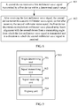
- FIG. 1 is a flowchart of a millimeter wave phased-array beam alignment method according to an embodiment of the present invention.
- Step 101 A first device communicates with a second device over a low-band communication link to determine a search angle.
- the first device may be a phased-array antenna device
- the second device is another phased-array antenna device that needs to be aligned with the first device.
- the two devices communicate with each other over a low-band communication link, such as a 2.4 GHz/5 GHz frequency band communication link, to determine a search angle from which searching and alignment are performed, where the search angle may be an included angle formed by means of clockwise or anticlockwise rotation relative to a horizontal direction or a vertical direction.
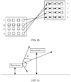
- the first device is a notebook computer 21, and the second device is a projector 22; the two devices communicate with each other over a low-band communication link to determine a search angle such as ⁇ 1 shown in FIG. 2a .
- Step 102 The first device transmits a first millimeter wave signal in a direction indicated by the search angle determined in step 101, to search for the second device.
- the first device transmits the first millimeter wave signal according to the search angle determined in the previous step, such as ⁇ 1 in FIG. 2a .
- the direction indicated by the search angle is also a direction in which a side of the search angle is located. If the search angle is relative to the horizontal direction, the direction indicated by the search angle may be a direction in which a side is located, where the side and the horizontal direction form an included angle.
- a millimeter wave may be a narrow beam, and a frequency of the millimeter wave may be but is not limited to 60 GHz.
- all millimeter wave signals (including a first millimeter wave signal, a second millimeter wave signal, and a wide beam millimeter wave signal) are high frequency millimeter wave signals, where the first millimeter wave signal and the second millimeter wave signal may be signals of a same frequency, and the wide beam millimeter wave signal may be a signal that has the same frequency as the first millimeter wave signal.
- the "first” and the "second” are used to distinguish millimeter wave signals transmitted by different devices, but are not specific references.
- the second device when the first device transmits a signal according to ⁇ 1, the second device starts to receive the first millimeter wave signal also according to the search angle. Regardless of whether the second device is located in a direction of ⁇ 1, the second device needs to receive the signal in the direction of ⁇ 1. If the second device is exactly located in a transmitting direction of the first millimeter wave signal, the second device can receive the first millimeter wave signal. In this case, the second device sends feedback information to the first device. If the second device is not located in the transmitting direction of the first millimeter wave signal, the second device cannot receive the first millimeter wave signal from the determined search angle, and the second device does not send feedback information to the first device.
- the projector 22 can receive, in a direction of ⁇ 1, a first millimeter wave signal transmitted by the notebook computer 21. In this case, the projector 22 sends feedback information to the notebook computer 21. If the included angle between the line connecting the projector 22 and the notebook computer 21 and the horizontal direction is ⁇ 2, the projector 22 cannot receive, in the direction of ⁇ 1, the first millimeter wave signal transmitted by the notebook computer 21. In this case, the projector 22 does not send feedback information to the notebook computer 21.
- Phased-array antenna planes of two devices are parallel, so as to determine a search angle, and if the planes are not parallel, compensation may be made for an included angle between the antenna planes by using internal vertical angle sensors of the devices.
- Step 101 may be performed again to determine another search angle, and then step 102 is performed again until the feedback information from the second device is received, and the second device is found by searching.
- step 102 is performed again until the feedback information from the second device is received, and the second device is found by searching.
- Another manner is as follows: In the previous step 101, the first device and the second device may determine multiple search angles, and then in step 102, the first device transmits millimeter wave signals one by one according to a specific angle order until the feedback information from the second device is received, and the second device is found by searching.
- Step 103 The first device receives feedback information sent by the second device, where the second device sends the feedback information after receiving the first millimeter wave signal in the direction indicated by the search angle.
- the second device After receiving, in the direction indicated by the determined search angle, the first millimeter wave signal sent by the first device, the second device sends the feedback information to the first device.
- that the first device receives feedback information sent by the second device may be specifically as follows:
- This manner is also that after the second device receives the first millimeter wave signal, the first device and the second device exchange roles with each other, and the second device transmits the second millimeter wave signal to the first device and a searching process repeats to determine a location of the first device.
- This process is similar to a searching manner in a blind searching process in the prior art.
- a beam coverage consists of M ⁇ M sub-areas, and a total quantity of sub-areas is M 2 .
- a horizontal angle is used as an example.
- the first device receives feedback information sent by the second device may be specifically as follows:
- the second device after receiving the first millimeter wave signal sent by the first device, the second device immediately sends an answer signal to the first device by using a 2.4 GHz or 5 GHz low frequency band, to instruct the first device to terminate a searching process, so as to avoid a subsequent invalid beam searching process.
- the feedback information that is, the answer signal may include a beam direction number of the first millimeter wave signal that is sent by the first device and received by the second device, such as a number of ⁇ 1. In this way, the first device learns which beam direction of a transmitting antenna the second device is located in.
- the second device does not give answer feedback to return this information to the first device, the second device and the first device need to exchange receiving and transmitting roles with each other, and beam scanning needs to be performed once again before beam pointing information can be exchanged, so as to complete a beam scanning and searching process. Therefore, according to the manner, in an answer method of the second device, a maximum of half times of scanning and searching may be reduced, thereby further improving phased-array beam alignment efficiency.
- Step 104 After receiving the feedback information, the first device determines to implement millimeter wave phased-array beam alignment with the second device in the direction indicated by the search angle.
- the first device can determine that the first device can implement millimeter wave phased-array beam alignment with the second device in the direction indicated by the search angle, that is, the first device is aligned with the second device in a receiving direction in which the second millimeter wave signal is received.
- the first device receives the feedback information, that is, the answer signal, sent by the second device over the low-band communication link, and the answer signal includes information that is used to indicate that the second device receives the first millimeter wave signal from the search angle, the first device can also learn that the first device can implement millimeter wave phased-array beam alignment with the second device in the direction indicated by the search angle. If the feedback information received by the first device includes beam direction information of the first millimeter wave signal received by the second device, the first device determines, after receiving the feedback information, to implement millimeter wave phased-array beam alignment with the second device in the beam direction that is of the first millimeter wave signal and in the feedback information.
- a low frequency band such as 2.4 GHz or 5 GHz in a device is used as an auxiliary communication link to determine a search angle, so that a first device and a second device perform, according to the search angle, a beam searching process by means of receiving and transmission collaboration, thereby implementing millimeter wave phased-array beam alignment.
- blindness of beam searching is reduced, and times of beam scanning are significantly reduced, thereby improving phased-array beam alignment efficiency, shortening time required for establishing a communication link in a millimeter wave frequency band such as 60 GHz, saving power consumption of a device, and enhancing user experience.
- the first device may further perform coarse positioning in advance on a location of the second device to determine a search range, where the search range refers to an angle range to which the search angle belongs.
- the search range refers to an angle range to which the search angle belongs.
- the first device divides an antenna coverage of the first device into several coverage areas (sectors), and the first device separately sends a wide beam millimeter wave signal to these areas (sectors).
- This signal includes numbers such as 1, 2, and 3 of these areas (sectors).
- the second device naturally learns that a signal received by the second device is sent, in which sector, by the first device, and then feeds back a number of this sector to the first device over the low-band communication link. In this way, the first device learns which sector coverage the second device falls within.
- the distance between the first device and the second device is less than or equal to the distance threshold, that is, the distance between the first device and the second device falls within a range of a valid communication distance between wide beams, two devices can find a rough location of each other by means of scanning and searching by using wider beams, so as to determine the search range.
- the process is similar to that in the prior art, and details are not described herein again.
- the method for determining the search range may include:
- a device height and/or a vertical angle between a device and the ground may be sensed by a height sensor and/or a vertical angle sensor, or the like disposed in both the first device and the second device, and may further be sensed by a built-in height information register, a device type register, or the like.
- the height information storage register is configured to: when a device generally works, store a height that is relative to the indoor ground and at which the device is located.
- the height may be a fixed value, and may be a height range.
- the height may be a factory default value, and may also be changed and set by a user.
- the device type register is configured to use a number to indicate a device type, such as a notebook computer, a television set, a mobile phone, or a projector.
- the second device may obtain the height information of the second device in a manner, for example, by reading information from the height information storage register, and then send the height information to the first device by using a low frequency band, such as 2.4 GHz or 5 GHz.
- a low frequency band such as 2.4 GHz or 5 GHz.
- Step 302 The first device determines a search range according to height information of the first device and the height information of the second device.
- the first device obtains the height information of the first device in a manner, for example, by reading information from the height information storage register, and then the first device can determine, according to the height information of the first device and the received height information of the second device, a rough angle, which is relative to a horizontal direction or a vertical direction, of a line connecting the two devices, and thereby can determine the search range.
- the first device and the second device may exchange information such as a device type and an antenna type with each other; therefore, a master and slave searching devices can be determined.
- the first device is a master searching device
- the second device is a slave searching device.
- the two devices may also be equivalent, and it is unnecessary to distinguish the master and slave searching devices.
- the first device communicates with the second device over the low-band communication link to determine the search angle within the search range.
- a search range is determined by means of coarse positioning, so that a beam scanning and searching range is further narrowed down, and times of beam scanning and searching are reduced, thereby establishing a communication link more quickly, reducing power consumption of a device, and enhancing user experience.
- a full search angle of the first device is ⁇ , and it is learned, by means of coarse positioning, that the second device is located within an angle range ⁇ 1 . Therefore, the first device needs to perform narrow beam scanning only within the small range ⁇ 1 , thereby narrowing down a search range and reducing times of scanning.
- the foregoing manners of determining a search angle that is, a manner in which a first device and a second device perform receiving and transmission collaboration, a manner in which the second device makes an answer over a low-band communication link, a manner of determining a search range by means of coarse positioning, and a blind searching manner in the prior art may be randomly combined according to a requirement, such as receiving and transmission collaboration, a combination of receiving and transmission collaboration and answer, a combination of coarse positioning and receiving and transmission collaboration, and a combination of coarse positioning, receiving and transmission collaboration, and answer. No detailed description is given herein again. For details, refer to descriptions of the foregoing embodiments.
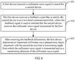
- FIG. 4 is a flowchart of another millimeter wave phased-array beam alignment method according to an embodiment of the present invention.
- a difference between this embodiment of the present invention and the foregoing embodiments lies in that the foregoing embodiments are described in terms of receiving and transmission collaboration, and a combination of receiving and transmission collaboration, coarse positioning, and/or answer, and this embodiment of the present invention is mainly described in terms of a combination of answer and another manner.
- the method may include:
- the first device is a phased-array antenna device
- the second device is another phased-array antenna device that needs to be aligned with the first device.
- the first device may transmit millimeter wave signals in multiple directions in a blind searching manner to search for the second device, and a frequency of the millimeter wave signal may be 60 GHz.
- Step 402 The first device receives feedback information that is sent by the second device over a low-band communication link, where the feedback information is used to indicate that the second device receives the millimeter wave signal transmitted by the first device.
- the second device After receiving a millimeter wave signal transmitted by the first device in a direction, the second device sends feedback information to the first device by using a low frequency band such as 2.4 GHz or 5 GHz, so as to make an answer, where the feedback information is used to indicate that the second device receives the millimeter wave signal transmitted by the first device.
- a low frequency band such as 2.4 GHz or 5 GHz
- the second device after receiving a first millimeter wave signal sent by the first device, the second device immediately sends an answer signal to the first device by using a low frequency band, that is, 2.4 GHz or 5 GHz, to instruct the first device to terminate a searching process, so as to avoid a subsequent invalid beam searching process.
- the answer signal may include a beam direction number that is sent by the first device and received by the second device, such as a number of ⁇ 1 shown in FIG. 2a . Therefore, the first device learns which beam direction of a transmitting antenna the second device is located in.
- Step 403 After receiving the feedback information, the first device determines to implement millimeter wave phased-array beam alignment with the second device in a transmitting direction of the millimeter wave signal.
- the first device After receiving the foregoing feedback information, that is, the answer signal, the first device can learn which angle the first device can implement millimeter wave phased-array beam alignment with the second device from.
- the feedback information includes beam direction information of the millimeter wave signal received by the second device.
- the first device determines to implement millimeter wave phased-array beam alignment with the second device in a beam direction that is of the millimeter wave signal and in the feedback information.
- a second device gives answer feedback to a first device to return related information in a received millimeter wave signal to the first device, thereby omitting a process in which the second device and the first device exchange receiving and transmitting roles with each other, and beam scanning needs to be performed once again before beam pointing information can be exchanged, so as to complete beam scanning and searching. Therefore, according to this manner, in an answer method of the second device, a maximum of half times of scanning and searching may be reduced, thereby further improving phased-array beam alignment efficiency, shortening time required for establishing a communication link in a millimeter wave frequency band such as 60 GHz, saving power consumption of a device, and enhancing user experience.
- a millimeter wave frequency band such as 60 GHz
- the first device before the first device transmits a millimeter wave signal to perform blind searching on the second device, the first device may further perform coarse positioning in advance on a location of the second device to determine a search range.
- the first device may further perform coarse positioning in advance on a location of the second device to determine a search range.
- search range There may be multiple manners for the process of determining the search range. For example,
- the method for determining the search range may include the following:
- the first device transmits the millimeter wave signal within the determined search range to search for the second device.
- a search range is determined by means of coarse positioning, so that a beam scanning and searching range is further narrowed down, and times of beam scanning and searching are reduced, thereby establishing a communication link more quickly, reducing power consumption of a device, and enhancing user experience.
- FIG. 5a is a flowchart of another millimeter wave phased-array beam alignment method according to an embodiment of the present invention.
- a difference between this embodiment of the present invention and the foregoing embodiments lies in that the foregoing embodiments are described in terms of receiving and transmission collaboration, a combination of receiving and transmission collaboration, coarse positioning, and/or answer, and a combination of answer and another manner, and this embodiment of the present invention is mainly described in terms of a method for a combination of coarse positioning and blind searching.
- the method may include:
- the method for determining the search range may include the following:
- Step 502 The first device transmits a first millimeter wave signal within the search range to search for the second device.
- Step 503 The first device receives a second millimeter wave signal transmitted by the second device, where the second device transmits the second millimeter wave signal after receiving the first millimeter wave signal.
- Step 504 After receiving the second millimeter wave signal, the first device determines to implement millimeter wave phased-array beam alignment with the second device in a direction in which the second millimeter wave signal is received.
- the first device is a signal transmitter
- the second device is a signal receiver.
- the first device searches for the second device, and after the second device receives a signal, the first device and the second device exchange roles with each other.
- a process in which the second device transmits a signal to search for the first device is the same as a searching process in the prior art, and details are not described herein again.
- a difference between the method and that in the prior art lies only in that in this embodiment, a search range is first determined by means of coarse positioning, and then the first device transmits a signal within the search range to perform searching.
- a search range is determined by means of coarse positioning, so that a beam scanning and searching range is narrowed down, and times of beam scanning and searching are reduced, thereby establishing a communication link more quickly, reducing power consumption of a device, and enhancing user experience.
- a beam coverage consists of M ⁇ M sub-areas, and a total quantity of sub-areas is M 2 .
- maximum possible times required for receiving a signal by a receiver are M 4 . If a transmitter transmits a beam searching sequence to each sub-area once, M 2 times are required, and a receiver needs to receive beam searching sequences in each direction for M 2 times. In a worst situation, required total times of searching are M 4 . However, after a search range is determined by means of the foregoing coarse positioning, maximum possible times of searching in a single direction may be reduced to M 4 ⁇ 1 ⁇ 2 .
- FIG. 6 is a flowchart of another millimeter wave phased-array beam alignment method according to an embodiment of the present invention.
- the method may include:
- a low frequency band such as 2.4 GHz or 5 GHz in a device is used as an auxiliary communication link to determine a search angle, so that a first device and a second device perform, according to the search angle, a beam searching process by means of receiving and transmission collaboration, thereby implementing millimeter wave phased-array beam alignment.
- blindness of beam searching is reduced, and times of beam scanning are significantly reduced, thereby improving phased-array beam alignment efficiency, shortening time required for establishing a communication link in a millimeter wave frequency band such as 60 GHz, saving power consumption of a device, and enhancing user experience.
- the second device sends feedback information to the first device includes the following:
- the second device sends feedback information to the first device includes the following:
- the feedback information includes beam direction information of the first millimeter wave signal received by the second device, so that after receiving the feedback information, the first device determines to implement millimeter wave phased-array beam alignment with the second device in a beam direction that is of the first millimeter wave signal and in the feedback information.
- the method before that a second device communicates with a first device over a low-band communication link to determine a search angle, the method further includes the following:
- That a second device communicates with a first device over a low-band communication link to determine a search angle is specifically as follows:
- the method before that a second device communicates with a first device over a low-band communication link to determine a search angle, the method further includes the following:
- That a second device communicates with a first device over a low-band communication link to determine a search angle is specifically as follows:
- FIG. 7 is a flowchart of another millimeter wave phased-array beam alignment method according to an embodiment of the present invention.
- the method may include:
- the feedback information may include beam direction information of the millimeter wave signal received by the second device, so that after receiving the feedback information, the first device determines to implement millimeter wave phased-array beam alignment with the second device in a beam direction that is of the millimeter wave signal and in the feedback information.
- a second device gives answer feedback to a first device to return related information in a received millimeter wave signal to the first device, thereby omitting a process in which the second device and the first device exchange receiving and transmitting roles with each other, and beam scanning needs to be performed once again before beam pointing information can be exchanged, so as to complete beam scanning and searching. Therefore, according to this manner, in an answer method of the second device, a maximum of half times of scanning and searching may be reduced, thereby further improving phased-array beam alignment efficiency, shortening time required for establishing a communication link in a millimeter wave frequency band such as 60 GHz, saving power consumption of a device, and enhancing user experience.
- the method before that a second device receives a millimeter wave signal transmitted by a first device, the method further includes the following:
- That a second device receives a millimeter wave signal transmitted by a first device is specifically as follows:
- the method before that a second device receives a millimeter wave signal transmitted by a first device, the method further includes the following:
- That a second device receives a millimeter wave signal transmitted by a first device is specifically as follows:
- FIG. 8 is a flowchart of another millimeter wave phased-array beam alignment method according to an embodiment of the present invention.
- the method may include:
- a search range is determined by means of coarse positioning, so that a beam scanning and searching range is narrowed down, and times of beam scanning and searching are reduced, thereby establishing a communication link more quickly, reducing power consumption of a device, and enhancing user experience.
- the method before that a second device receives a first millimeter wave signal transmitted by a first device within a determined search range, the method further includes the following:
- the method before that a second device receives a first millimeter wave signal transmitted by a first device within a determined search range, the method further includes the following:
- a frequency of a millimeter wave band is not limited to approximately 60 GHz, and the millimeter wave band may be a millimeter wave band that covers an entire frequency band from 20 GHz to 100 GHz.
- a low frequency band frequency is not limited to a 2.4 GHz/5 GHz frequency band, and may also be any authorized and usable frequency from 30 MHz to 10 GHz.
- a millimeter wave signal transmitted between a first device and a second device may be specifically a narrow beam millimeter wave signal.
- This embodiment of the present invention is not only applied to a millimeter wave standard, such as a 802.11 standard family, a 802.15 standard family (802.15.3c), WiGig, WirelessHD, ISO/IEC 13156, or a combination of these standards.
- a millimeter wave standard such as a 802.11 standard family, a 802.15 standard family (802.15.3c), WiGig, WirelessHD, ISO/IEC 13156, or a combination of these standards.
- FIG. 9 is a schematic structural diagram of a communications device according to an embodiment of the present invention.
- the communications device 900 may include:
- a low frequency band such as 2.4 GHz or 5 GHz is used as an auxiliary communication link to determine a search angle, so that the communications device and a second device perform, according to the search angle, a beam searching process by means of receiving and transmission collaboration, thereby implementing millimeter wave phased-array beam alignment.
- blindness of beam searching is reduced, and times of beam scanning are significantly reduced, thereby improving phased-array beam alignment efficiency, shortening time required for establishing a communication link in a millimeter wave frequency band such as 60 GHz, saving power consumption of a device, and enhancing user experience.
- the signal receiving unit is specifically configured to receive, in the direction indicated by the search angle, a second millimeter wave signal transmitted by the second device in the direction indicated by the search angle, where the second device transmits the second millimeter wave signal after receiving the first millimeter wave signal in the direction indicated by the search angle, and the second millimeter wave signal is a high frequency millimeter wave signal.
- the aligning unit is specifically configured to: after the signal receiving unit receives the second millimeter wave signal, determine to implement millimeter wave phased-array beam alignment with the second device in the direction indicated by the search angle.
- the signal receiving unit is specifically configured to receive the feedback information sent by the second device over the low-band communication link, where the feedback information is used to indicate that the second device receives the first millimeter wave signal from the search angle.
- the feedback information received by the signal receiving unit includes beam direction information of the first millimeter wave signal received by the second device.
- the aligning unit is specifically configured to: after the signal receiving unit receives the feedback information, determine to implement millimeter wave phased-array beam alignment with the second device in a beam direction that is of the first millimeter wave signal and in the feedback information.
- the communications device may further include:
- the angle determining unit is specifically configured to communicate with the second device over the low-band communication link to determine the search angle within the search range.
- the communications device may further include:
- the angle determining unit is specifically configured to communicate with the second device over the low-band communication link to determine the search angle within the search range.
- FIG. 10 is a schematic structural diagram of another communications device according to an embodiment of the present invention.
- the communications device 1000 may include:
- the feedback information received by the signal receiving unit includes beam direction information of the millimeter wave signal received by the second device.
- the aligning unit is specifically configured to: after the signal receiving unit receives the feedback information, determine to implement millimeter wave phased-array beam alignment with the second device in a beam direction that is of the millimeter wave signal and in the feedback information.
- a device receives answer feedback sent by a second device to the communications device, thereby omitting a process in which the second device and the communications device exchange receiving and transmitting roles with each other, and beam scanning needs to be performed once again before beam pointing information can be exchanged, so as to complete beam scanning and searching. Therefore, according to the device, a maximum of half times of scanning and searching may be reduced, thereby further improving phased-array beam alignment efficiency, shortening time required for establishing a communication link in a millimeter wave frequency band such as 60 GHz, saving power consumption of a device, and enhancing user experience.
- the communications device may further include:
- the signal transmitting unit is specifically configured to transmit the millimeter wave signal within the search range to search for the second device.
- the communications device may further include:
- the signal transmitting unit is specifically configured to transmit the millimeter wave signal within the search range to search for the second device.
- FIG. 11 is a schematic structural diagram of another communications device according to an embodiment of the present invention.
- the communications device 1100 may include:
- Both the first millimeter wave signal and the second millimeter wave signal are high frequency millimeter wave signals.
- a device determines a search range by means of coarse positioning, so that a beam scanning and searching range is narrowed down, and times of beam scanning and searching are reduced, thereby establishing a communication link more quickly, reducing power consumption of a device, and enhancing user experience.
- the range determining unit is specifically configured to: when a distance between the communications device and the second device is less than or equal to a distance threshold, transmit a wide beam millimeter wave signal to search for the second device, where the wide beam millimeter wave signal is a high frequency millimeter wave signal; receive signal belonging information sent by the second device, where the signal belonging information includes an antenna sector of the communications device to which the wide beam millimeter wave signal that is received by the second device belongs; and determine an angle range, which is indicated by the antenna sector, as the search range.
- the range determining unit includes:
- FIG. 12 is a schematic structural diagram of another communications device according to an embodiment of the present invention.
- the communications device 1200 may include:
- the feedback unit is specifically configured to: after the signal receiving unit receives the first millimeter wave signal, transmit a second millimeter wave signal in the direction indicated by the search angle, so that after receiving the second millimeter wave signal in the direction indicated by the search angle, the first device determines to implement millimeter wave phased-array beam alignment with the communications device in the direction indicated by the search angle, where the second millimeter wave signal is a high frequency millimeter wave signal.
- the feedback unit is specifically configured to: after the signal receiving unit receives the first millimeter wave signal, send the feedback information to the first device over the low-band communication link, where the feedback information is used to indicate that the communications device receives the first millimeter wave signal in the direction indicated by the search angle.
- the feedback information includes beam direction information of the first millimeter wave signal received by the signal receiving unit, so that after receiving the feedback information, the first device determines to implement millimeter wave phased-array beam alignment with the communications device in a beam direction that is of the first millimeter wave signal and in the feedback information.
- the signal receiving unit is further configured to: before the angle determining unit communicates with the first device over the low-band communication link to determine the search angle, when a distance between the communications device and the first device is less than or equal to a distance threshold, receive a wide beam millimeter wave signal transmitted by the first device, where the wide beam millimeter wave signal is a high frequency millimeter wave signal.
- the feedback unit is further configured to: after the signal receiving unit receives the wide beam millimeter wave signal, send signal belonging information to the first device, where the signal belonging information includes an antenna sector of the first device to which the wide beam millimeter wave signal that is received by the communications device belongs, so that the first device determines an angle range, which is indicated by the antenna sector, as a search range.
- the angle determining unit is specifically configured to communicate with the first device over the low-band communication link to determine the search angle within the search range.
- the communications device further includes:
- the angle determining unit is specifically configured to communicate with the first device over the low-band communication link to determine the search angle within the search range.
- FIG. 13 is a schematic structural diagram of another communications device according to an embodiment of the present invention.
- the communications device 1300 may include:
- the feedback information may include beam direction information of the millimeter wave signal received by the communications device, so that after receiving the feedback information, the first device determines to implement millimeter wave phased-array beam alignment with the communications device in a beam direction that is of the millimeter wave signal and in the feedback information.
- the signal receiving unit is further configured to: before the millimeter wave signal transmitted by the first device is received, when a distance between the communications device and the first device is less than or equal to a distance threshold, receive a wide beam millimeter wave signal transmitted by the first device, where the wide beam millimeter wave signal is a high frequency millimeter wave signal.
- the feedback unit is further configured to: after the signal receiving unit receives the wide beam millimeter wave signal, send signal belonging information to the first device, where the signal belonging information includes an antenna sector of the first device to which the wide beam millimeter wave signal that is received by the communications device belongs, so that the first device determines an angle range, which is indicated by the antenna sector, as a search range.
- the signal receiving unit is specifically configured to receive, within the search range, the millimeter wave signal transmitted by the first device.
- the communications device further includes:
- FIG. 14 is a schematic structural diagram of another communications device according to an embodiment of the present invention.
- the communications device 1400 may include:
- the signal receiving unit is further configured to: before the first millimeter wave signal transmitted by the first device within the determined search range is received, when a distance between the communications device and the first device is less than or equal to a distance threshold, receive a wide beam millimeter wave signal transmitted by the first device, where the wide beam millimeter wave signal is a high frequency millimeter wave signal.
- the signal transmitting unit is further configured to: after the signal receiving unit receives the wide beam millimeter wave signal, send signal belonging information to the first device, where the signal belonging information includes an antenna sector of the first device to which the wide beam millimeter wave signal that is received by the communications device belongs, so that the first device determines an angle range, which is indicated by the antenna sector, as the search range.
- the communications device further includes:
- An embodiment of the present invention further provides a millimeter wave phased-array beam alignment system, where the system may include the communications device according to the foregoing embodiment shown in FIG. 9 and the communications device according to the foregoing embodiment shown in FIG. 12 .
- An embodiment of the present invention further provides a millimeter wave phased-array beam alignment system, where the system may include the communications device according to the foregoing embodiment shown in FIG. 10 and the communications device according to the foregoing embodiment shown in FIG. 13 .
- An embodiment of the present invention further provides a millimeter wave phased-array beam alignment system, where the system may include the communications device according to the foregoing embodiment shown in FIG. 11 and the communications device according to the foregoing embodiment shown in FIG. 14 .
- An embodiment of the present invention further provides a communications device, where the communications device may include a transceiver, a memory, and a processor.
- the transceiver is configured to: transmit a first millimeter wave signal according to a search angle to search for a second device; and receive feedback information sent by the second device, where the second device sends the feedback information after receiving the first millimeter wave signal from the search angle.
- the memory stores a group of program code
- the processor is configured to invoke the program code stored in the memory, so as to perform the following operations:
- An embodiment of the present invention further provides a communications device, where the communications device may include a transceiver, a memory, and a processor.
- the transceiver is configured to: transmit a millimeter wave signal to search for a second device; and receive feedback information sent by the second device over a low-band communication link, where the feedback information is used to indicate that the second device receives the millimeter wave signal transmitted by the first device.
- the memory stores a group of program code
- the processor is configured to invoke the program code stored in the memory, so as to perform the following operation:
- An embodiment of the present invention further provides a communications device, where the communications device may include a transceiver, a memory, and a processor.
- the transceiver receives a second millimeter wave signal transmitted by a second device, where the second device transmits the second millimeter wave signal after receiving a first millimeter wave signal; and transmits the first millimeter wave signal within a search range to search for the second device.
- the memory stores a group of program code
- the processor is configured to invoke the program code stored in the memory, so as to perform the following operations:
- An embodiment of the present invention further provides a communications device, where the communications device may include a transceiver, a memory, and a processor.
- the transceiver is configured to: receive, from a search angle, a first millimeter wave signal transmitted by a first device; and after the first millimeter wave signal is received, send feedback information to the first device, so that after receiving the feedback information, the first device determines to implement millimeter wave phased-array beam alignment with the second device from the search angle.
- the memory stores a group of program code
- the processor is configured to invoke the program code stored in the memory, so as to perform the following operation:
- An embodiment of the present invention further provides a communications device, where the communications device may include a transceiver.
- the transceiver is configured to: receive a millimeter wave signal transmitted by a first device; and after the millimeter wave signal is received, send feedback information to the first device over a low-band communication link, where the feedback information is used to indicate that the second device receives the millimeter wave signal transmitted by the first device, so that after receiving the feedback information, the first device determines to implement millimeter wave phased-array beam alignment with the second device from a transmitting angle from which the millimeter wave signal is transmitted.
- An embodiment of the present invention further provides a communications device, where the communications device may include a transceiver.
- the transceiver is configured to: receive a first millimeter wave signal transmitted by a first device within a determined search range; and after the first millimeter wave signal is received, transmit a second millimeter wave signal, so that after receiving the second millimeter wave signal, the first device determines to implement millimeter wave phased-array beam alignment with the second device from a transmitting angle from which the first millimeter wave signal is transmitted.
- the disclosed system, apparatus, and method may be implemented in other manners.
- the described apparatus embodiment is merely exemplary.
- the unit division is merely logical function division and may be other division in actual implementation.
- a plurality of units or components may be combined or integrated into another system, or some features may be ignored or not performed.
- the displayed or discussed mutual couplings or direct couplings or communication connections may be implemented through some interfaces.
- the indirect couplings or communication connections between the apparatuses or units may be implemented in electronic, mechanical, or other forms.
- the units described as separate parts may or may not be physically separate, and parts displayed as units may or may not be physical units, may be located in one position, or may be distributed on a plurality of network units. Some or all of the units may be selected according to actual requirements to achieve the purposes of the solutions of the embodiments.
- functional units in the embodiments of the present invention may be integrated into one processing unit, or each of the units may exist alone physically, or two or more units are integrated into one unit.
- the functions When the functions are implemented in the form of a software functional unit and sold or used as an independent product, the functions may be stored in a computer-readable storage medium. Based on such an understanding, the technical solutions of the present invention essentially, or the part contributing to the prior art, or a part of the technical solutions may be implemented in a form of a software product.
- the software product is stored in a storage medium and includes several instructions for instructing a computer device (which may be a personal computer, a server, or a network device) or a processor (processor) to perform all or a part of the steps of the methods described in the embodiments of the present invention.
- the foregoing storage medium includes: any medium that can store program code, such as a USB flash drive, a removable hard disk, a read-only memory (ROM, Read-Only Memory), a random access memory (RAM, Random Access Memory), a magnetic disk, or an optical disc.
- program code such as a USB flash drive, a removable hard disk, a read-only memory (ROM, Read-Only Memory), a random access memory (RAM, Random Access Memory), a magnetic disk, or an optical disc.
Landscapes
- Engineering & Computer Science (AREA)
- Computer Networks & Wireless Communication (AREA)
- Signal Processing (AREA)
- Radio Transmission System (AREA)
- Mobile Radio Communication Systems (AREA)
Claims (9)
- Strahlausrichtungsverfahren für eine phasengesteuerte Millimeterwellen-Antennengruppe, das Folgendes umfasst:Bestimmen (501) durch eine erste Vorrichtung eines Suchbereichs, innerhalb dessen nach einer zweiten Vorrichtung gesucht wird;Übertragen (502) durch die erste Vorrichtung eines ersten Millimeterwellensignals innerhalb des Suchbereichs, um nach der zweiten Vorrichtung zu suchen;Empfangen (503) durch die erste Vorrichtung eines zweiten Millimeterwellensignals, das durch die zweite Vorrichtung übertragen wird, wobei die zweite Vorrichtung das zweite Millimeterwellensignal nach dem Empfangen des ersten Millimeterwellensignals überträgt; undBestimmen (504) durch die erste Vorrichtung nach dem Empfangen des zweiten Millimeterwellensignals, Strahlausrichtung für eine phasengesteuerte Millimeterwellen-Antennengruppe innerhalb der zweiten Vorrichtung in einer Richtung, in der das zweite Millimeterwellensignal empfangen wird, zu implementieren; wobeisowohl das erste Millimeterwellensignal als auch das zweite Millimeterwellensignal Hochfrequenz-Millimeterwellensignale sind, die eine Frequenz eines Frequenzbands von 20 GHz bis 100 GHz aufweisen; dadurch gekennzeichnet, dassdas Bestimmen (501) durch eine erste Vorrichtung eines Suchbereichs, innerhalb dessen nach einer zweiten Vorrichtung gesucht wird, Folgendes umfasst:Empfangen durch die erste Vorrichtung von Höheninformationen der zweiten Vorrichtung über eine Niederbandkommunikationsstrecke, wobei ein Niederfrequenzband von 30 MHz bis 10 GHz als die Niederbandkommunikationsstrecke verwendet wird; undBestimmen durch die erste Vorrichtung des Suchbereichs gemäß den Höheninformationen der ersten Vorrichtung und den Höheninformationen der zweiten Vorrichtung.
- Verfahren nach Anspruch 1, wobei das Bestimmen (501) durch eine erste Vorrichtung eines Suchbereichs, innerhalb dessen nach einer zweiten Vorrichtung gesucht wird, Folgendes umfasst:wenn ein Abstand zwischen der ersten Vorrichtung und der zweiten Vorrichtung kleiner als ein oder gleich einem Abstandsschwellenwert ist, Übertragen durch die erste Vorrichtung eines Breitstrahl-Millimeterwellensignals, um nach der zweiten Vorrichtung zu suchen, wobei das Breitstrahl-Millimeterwellensignal ein Hochfrequenz-Millimeterwellensignal ist, das eine Frequenz eines Frequenzbands von 20 GHz bis 100 GHz aufweist;Empfangen durch die erste Vorrichtung, von signalzugehörigen Informationen, die durch die zweite Vorrichtung gesendet werden, wobei die signalzugehörigen Informationen einen Antennensektor der ersten Vorrichtung umfassen, zu dem das Breitstrahl-Millimeterwellensignal, das durch die zweite Vorrichtung empfangen wird, gehört; undBestimmen durch die erste Vorrichtung eines Winkelbereichs, der durch den Antennensektor angegeben ist, als den Suchbereich.
- Strahlausrichtungsverfahren for eine phasengesteuerte Millimeterwellen-Antennengruppe, das Folgendes umfasst:Empfangen (801) durch eine zweite Vorrichtung eines ersten Millimeterwellensignals, das durch eine erste Vorrichtung innerhalb eines bestimmten Suchbereichs übertragen wird; undÜbertragen (802) durch die zweite Vorrichtung nach dem Empfangen des ersten Millimeterwellensignals eines zweiten Millimeterwellensignals, so dass die erste Vorrichtung nach dem Empfangen des zweite Millimeterwellensignals bestimmt, Strahlausrichtung für eine phasengesteuerte Millimeterwellen-Antennengruppe mit der zweiten Vorrichtung in einer Richtung, in der das zweite Millimeterwellensignal empfangen wird, zu implementieren, wobei sowohl das erste Millimeterwellensignal als auch das zweite Millimeterwellensignal Hochfrequenz-Millimeterwellensignale sind, die eine Frequenz eines Frequenzbands von 20 GHz bis 100 GHz aufweisen; dadurch gekennzeichnet, dassdas Verfahren vor dem Empfangen (801) durch eine zweite Vorrichtung eines ersten Millimeterwellensignals, das durch eine erste Vorrichtung innerhalb eines bestimmten Suchbereichs übertragen wird, ferner Folgendes umfasst:Senden durch die zweite Vorrichtung von Höheninformationen der zweiten Vorrichtung zu der ersten Vorrichtung über eine Niederbandkommunikationsstrecke, so dass die erste Vorrichtung den Suchbereich gemäß den Höheninformationen der ersten Vorrichtung und den Höheninformationen der zweiten Vorrichtung bestimmt, wobei ein Niederfrequenzband von 30 MHz bis 10 GHz als die Niederbandkommunikationsstrecke verwendet wird.
- Verfahren nach Anspruch 3, wobei das Verfahren vor dem Empfangen (801) durch eine zweite Vorrichtung eines ersten Millimeterwellensignals, das durch eine erste Vorrichtung innerhalb eines bestimmten Suchbereichs übertragen wird, ferner Folgendes umfasst:wenn ein Abstand zwischen der zweiten Vorrichtung und der ersten Vorrichtung kleiner als ein oder gleich einem Abstandsschwellenwert ist, Empfangen durch die zweite Vorrichtung eines Breitstrahl-Millimeterwellensignals, das durch die erste Vorrichtung übertragen wird, wobei das Breitstrahl-Millimeterwellensignal ein Hochfrequenz-Millimeterwellensignal ist, das eine Frequenz eines Frequenzbands von 20 GHz bis 100 GHz aufweist; undSenden durch die zweite Vorrichtung nach dem Empfangen des Breitstrahl-Millimeterwellensignals von signalzugehörigen Informationen zu der ersten Vorrichtung, wobei die signalzugehörigen Informationen einen Antennensektor der ersten Vorrichtung umfassen, zu dem das Breitstrahl-Millimeterwellensignal, das durch die zweite Vorrichtung empfangen wird, gehört, so dass die erste Vorrichtung einen Winkelbereich, der durch den Antennensektor angegeben ist, als den Suchbereich bestimmt.
- Kommunikationsvorrichtung (1100), die Folgendes umfasst:eine Bereichsbestimmungseinheit (1101), die konfiguriert ist, einen Suchbereich, innerhalb dessen nach einer zweiten Vorrichtung gesucht wird, zu bestimmen;eine Signalübertragungseinheit (1102), die konfiguriert ist, ein erstes Millimeterwellensignal innerhalb des Suchbereichs zu übertragen, um nach der zweiten Vorrichtung zu suchen;eine Signalempfangseinheit (1103), die konfiguriert ist, ein zweites Millimeterwellensignal, das durch die zweite Vorrichtung übertragen wird, zu empfangen, wobei die zweite Vorrichtung das zweite Millimeterwellensignal nach dem Empfangen des ersten Millimeterwellensignals überträgt; undeine Ausrichtungseinheit (1104), die konfiguriert ist: nachdem das zweite Millimeterwellensignal empfangen wird, zu bestimmen, Strahlausrichtung für eine phasengesteuerte Millimeterwellen-Antennengruppe mit der zweiten Vorrichtung in einer Richtung, in der das zweite Millimeterwellensignal empfangen wird, zu implementieren; wobeisowohl das erste Millimeterwellensignal als auch das zweite Millimeterwellensignal Hochfrequenz-Millimeterwellensignale sind, die eine Frequenz eines Frequenzbands von 20 GHz bis 100 GHz aufweisen; dadurch gekennzeichnet, dass die Bereichsbestimmungseinheit (1101) Folgendes umfasst:eine Empfangsuntereinheit, die konfiguriert ist, Höheninformationen der zweiten Vorrichtung über eine Niederbandkommunikationsstrecke zu empfangen, wobei ein Niederfrequenzband von 30 MHz bis 10 GHz als die Niederbandkommunikationsstrecke verwendet wird; undeine Bestimmungsuntereinheit, die konfiguriert ist, den Suchbereich gemäß den Höheninformationen der Kommunikationsvorrichtung und den Höheninformationen der zweiten Vorrichtung zu bestimmen.
- Kommunikationsvorrichtung (1100) nach Anspruch 5, wobei:die Bereichsbestimmungseinheit (1101) insbesondere konfiguriert ist: wenn ein Abstand zwischen der Kommunikationsvorrichtung und der zweiten Vorrichtung kleiner als ein oder gleich einem Abstandsschwellenwert ist, ein Breitstrahl-Millimeterwellensignal zu übertragen, um nach der zweiten Vorrichtung zu suchen, wobei das Breitstrahl-Millimeterwellensignal ein Hochfrequenz-Millimeterwellensignal ist, das eine Frequenz eines Frequenzbands von 20 GHz bis 100 GHz aufweist; signalzugehörige Informationen zu empfangen, die durch die zweite Vorrichtung gesendet werden, wobei die signalzugehörigen Informationen einen Antennensektor der Kommunikationsvorrichtung umfassen, zu dem das Breitstrahl-Millimeterwellensignal, das durch die zweite Vorrichtung empfangen wird, gehört; und einen Winkelbereich, der durch den Antennensektor angegeben ist, als den Suchbereich zu bestimmen.
- Kommunikationsvorrichtung (1400), die Folgendes umfasst:eine Signalempfangseinheit (1401), die konfiguriert ist, ein erstes Millimeterwellensignal zu empfangen, das durch eine erste Vorrichtung innerhalb eines bestimmten Suchbereichs übertragen wird;eine Signalübertragungseinheit (1402), die konfiguriert ist: nachdem die Signalempfangseinheit das erste Millimeterwellensignal empfangt, ein zweites Millimeterwellensignal zu übertragen, so dass die erste Vorrichtung nach dem Empfangen des zweiten Millimeterwellensignals bestimmt, Strahlausrichtung für eine phasengesteuerte Millimeterwellen-Antennengruppe mit der Kommunikationsvorrichtung in einer Richtung, in der das zweite Millimeterwellensignal empfangen wird, zu implementieren, wobei sowohl das erste Millimeterwellensignal als auch das zweite Millimeterwellensignal Hochfrequenz-Millimeterwellensignale sind, die eine Frequenz eines Frequenzbands von 20 GHz bis 100 GHz aufweisen; gekennzeichnet durcheine Höheninformationssendeeinheit, die konfiguriert ist: bevor die Signalempfangseinheit das erste Millimeterwellensignal empfängt, das durch die erste Vorrichtung innerhalb des bestimmten Suchbereichs übertragen wird, Höheninformationen der Kommunikationsvorrichtung zu der ersten Vorrichtung über die Niederbandkommunikationsstrecke zu senden, so dass die erste Vorrichtung den Suchbereich gemäß den Höheninformationen der ersten Vorrichtung und den Höheninformationen der Kommunikationsvorrichtung bestimmt, wobei ein Niederfrequenzband von 30 MHz bis 10 GHz als die Niederbandkommunikationsstrecke verwendet wird.
- Kommunikationsvorrichtung (1400) nach Anspruch 7, wobei:die Signalempfangseinheit (1401) ferner konfiguriert ist: bevor das erste Millimeterwellensignal, das durch die erste Vorrichtung innerhalb des bestimmten Suchbereichs übertragen wird, empfangen wird, wenn ein Abstand zwischen der Kommunikationsvorrichtung und der ersten Vorrichtung kleiner als ein oder gleich einem Abstandsschwellenwert ist, ein Breitstrahl-Millimeterwellensignal zu empfangen, das durch die erste Vorrichtung übertragen wird, wobei das Breitstrahl-Millimeterwellensignal ein Hochfrequenz-Millimeterwellensignal ist, das eine Frequenz eines Frequenzbands von 20 GHz bis 100 GHz aufweist; unddie Signalübertragungseinheit (1402) ferner konfiguriert ist: nachdem die Signalempfangseinheit das Breitstrahl-Millimeterwellensignal empfängt, signalzugehörige Informationen zu der ersten Vorrichtung zu senden, wobei die signalzugehörigen Informationen einen Antennensektor der ersten Vorrichtung umfassen, zu dem das Breitstrahl-Millimeterwellensignal, das durch die Kommunikationsvorrichtung empfangen wird, gehört, so dass die erste Vorrichtung einen Winkelbereich, der durch den Antennensektor angegeben ist, als den Suchbereich bestimmt.
- Strahlausrichtungssystem für eine phasengesteuerte Millimeterwellen-Antennengruppe, das die Kommunikationsvorrichtung (1100) nach einem der Ansprüche 5 und 6 und die Kommunikationsvorrichtung (1400) nach einem der Ansprüche 7 und 8 umfasst.
Applications Claiming Priority (2)
| Application Number | Priority Date | Filing Date | Title |
|---|---|---|---|
| CN201310023438.7A CN103052086B (zh) | 2013-01-22 | 2013-01-22 | 一种毫米波相控阵波束对准方法及通信设备 |
| PCT/CN2014/071125 WO2014114237A1 (zh) | 2013-01-22 | 2014-01-22 | 一种毫米波相控阵波束对准方法及通信设备 |
Publications (3)
| Publication Number | Publication Date |
|---|---|
| EP2945411A1 EP2945411A1 (de) | 2015-11-18 |
| EP2945411A4 EP2945411A4 (de) | 2015-12-16 |
| EP2945411B1 true EP2945411B1 (de) | 2016-12-21 |
Family
ID=48064558
Family Applications (1)
| Application Number | Title | Priority Date | Filing Date |
|---|---|---|---|
| EP14743340.3A Active EP2945411B1 (de) | 2013-01-22 | 2014-01-22 | Millimeterwellen-phasengesteuertes strahlenausrichtungsverfahren und kommunikationsvorrichtung |
Country Status (6)
| Country | Link |
|---|---|
| US (1) | US20150325912A1 (de) |
| EP (1) | EP2945411B1 (de) |
| JP (1) | JP6085374B2 (de) |
| CN (1) | CN103052086B (de) |
| AU (1) | AU2014210248B2 (de) |
| WO (1) | WO2014114237A1 (de) |
Families Citing this family (31)
| Publication number | Priority date | Publication date | Assignee | Title |
|---|---|---|---|---|
| CN104184504B (zh) * | 2013-05-27 | 2019-01-25 | 中兴通讯股份有限公司 | 一种毫米波通信空间复用传输方法及毫米波通信设备 |
| CN104661321A (zh) * | 2013-11-15 | 2015-05-27 | 中兴通讯股份有限公司 | 通信链路管理方法、设备和系统 |
| EP3217737B1 (de) * | 2014-12-29 | 2019-09-25 | Huawei Technologies Co., Ltd. | Verfahren und vorrichtung zum ausrichten von antennenstrahlen eines hoch-/niederfrequenten co-stationsnetzwerkes |
| WO2016106620A1 (zh) * | 2014-12-31 | 2016-07-07 | 华为技术有限公司 | 一种天线对准方法和系统 |
| CN104935366B (zh) * | 2015-04-21 | 2018-01-02 | 北京航空航天大学 | 毫米波通信中的波束搜索方法 |
| CN106341873A (zh) * | 2015-07-08 | 2017-01-18 | 中兴通讯股份有限公司 | 一种数据通信方法和装置 |
| CN106454871A (zh) * | 2015-08-06 | 2017-02-22 | 中兴通讯股份有限公司 | 一种波束使用方法及装置 |
| US9787538B2 (en) * | 2015-10-15 | 2017-10-10 | Intel IP Corporation | Wireless gigabit-enabled device configuration |
| CN107181517B (zh) * | 2016-03-09 | 2021-06-15 | 中兴通讯股份有限公司 | 波束搜索方法及装置 |
| WO2017162301A1 (en) | 2016-03-24 | 2017-09-28 | Telefonaktiebolaget Lm Ericsson (Publ) | A wireless communication node adapted to radiate antenna beams of different types |
| KR101881166B1 (ko) * | 2016-05-17 | 2018-07-23 | 한국전자통신연구원 | 이동무선백홀 네트워크의 빔 포밍 통신 장치 및 방법 |
| US10313070B2 (en) | 2016-11-03 | 2019-06-04 | Futurewei Technologies, Inc. | Fast millimeter-wave cell acquisition |
| KR102713992B1 (ko) * | 2016-12-21 | 2024-10-07 | 삼성전자 주식회사 | 무선 통신 시스템에서 단말의 빔 결정 방법 및 이를 위한 단말 |
| CN106851560B (zh) * | 2016-12-30 | 2020-05-05 | 上海无线通信研究中心 | 一种高频通信链路的建立方法、系统和电子设备 |
| CN108282215B (zh) * | 2017-01-06 | 2019-07-09 | 华为技术有限公司 | 一种波束匹配方法及装置 |
| CN108667550B (zh) | 2017-03-28 | 2020-02-14 | 华为技术有限公司 | 一种干扰协调方法及装置 |
| CN108736929B (zh) * | 2017-04-18 | 2020-03-17 | 大唐移动通信设备有限公司 | 一种波束检测方法及装置 |
| US10172018B2 (en) * | 2017-06-06 | 2019-01-01 | Phazr, Inc. | Wireless systems and methods using millimeter wave band signals with asymmetric directivity |
| US10165426B1 (en) | 2017-06-22 | 2018-12-25 | Apple Inc. | Methods for maintaining line-of-sight communications |
| CN107172630B (zh) * | 2017-06-29 | 2019-11-19 | 电子科技大学 | 用于高铁的基于分布式波束成形毫米波覆盖方法 |
| CN111742572B (zh) | 2018-02-23 | 2022-05-24 | 华为技术有限公司 | 用于调整接收波束的方法及装置 |
| CN113036456B (zh) * | 2018-02-28 | 2024-07-05 | 华为技术有限公司 | 一种天线装置及相关设备 |
| US10432798B1 (en) | 2018-05-25 | 2019-10-01 | At&T Intellectual Property I, L.P. | System, method, and apparatus for service grouping of users to different speed tiers for wireless communication |
| US10419943B1 (en) | 2018-06-15 | 2019-09-17 | At&T Intellectual Property I, L.P. | Overlay of millimeter wave (mmWave) on citizens broadband radio service (CBRS) for next generation fixed wireless (NGFW) deployment |
| US10798537B2 (en) | 2018-07-09 | 2020-10-06 | At&T Intellectual Property I, L.P. | Next generation fixed wireless qualification tool for speed-tier based subscription |
| TWI735933B (zh) * | 2018-08-22 | 2021-08-11 | 群邁通訊股份有限公司 | 毫米波訊號的測量方法及裝置 |
| EP3890418A4 (de) * | 2018-11-29 | 2022-10-19 | Beijing Xiaomi Mobile Software Co., Ltd. | Verfahren, einrichtung und vorrichtung zur bestimmung des strahlabtastbereichs und speichermedium |
| KR102399317B1 (ko) | 2019-07-30 | 2022-05-18 | 한양대학교 산학협력단 | 무선 통신 시스템에서 위치 정보에 기반한 빔 정렬 장치 및 방법 |
| CN112367672B (zh) * | 2020-09-29 | 2022-04-15 | 北京邮电大学 | 一种室内波束搜索与追踪方法、装置和电子设备 |
| US11476909B2 (en) * | 2020-11-23 | 2022-10-18 | Hewlett Packard Enterprise Development Lp | Automatic antenna beam alignment |
| CN113613349A (zh) * | 2021-08-16 | 2021-11-05 | 深圳市九洲电器有限公司 | 基于毫米波的智能终端组网装置和方法 |
Family Cites Families (11)
| Publication number | Priority date | Publication date | Assignee | Title |
|---|---|---|---|---|
| US7710319B2 (en) * | 2006-02-14 | 2010-05-04 | Sibeam, Inc. | Adaptive beam-steering methods to maximize wireless link budget and reduce delay-spread using multiple transmit and receive antennas |
| CN101075837B (zh) * | 2007-06-28 | 2010-05-19 | 中国电子科技集团公司第五十四研究所 | 散射通信天线快速对准方法 |
| WO2009093182A2 (en) * | 2008-01-25 | 2009-07-30 | Koninklijke Philips Electronics N.V. | A method for communicating a signal using analog beam steering, a transmitting station, a receiving station and a preamble structure therefor |
| US9100068B2 (en) * | 2008-03-17 | 2015-08-04 | Qualcomm, Incorporated | Multi-resolution beamforming in MIMO systems |
| KR101478843B1 (ko) * | 2009-01-22 | 2015-01-05 | 엘지전자 주식회사 | 협력적 다중 셀 무선통신 시스템에서 데이터를 송신하는 방법 |
| CN102483452A (zh) * | 2009-06-30 | 2012-05-30 | 诺基亚公司 | 装置和方法 |
| CN101616472B (zh) * | 2009-07-28 | 2011-04-13 | 深圳大学 | 一种发射波束跟踪方法、系统及发射端设备 |
| JP2012191281A (ja) * | 2011-03-09 | 2012-10-04 | Hitachi Consumer Electronics Co Ltd | 無線通信装置 |
| CN102164374B (zh) * | 2011-05-10 | 2013-09-11 | 华为技术有限公司 | 波束搜索处理方法、装置和系统 |
| CN103378892A (zh) * | 2012-04-28 | 2013-10-30 | 中兴通讯股份有限公司 | 一种毫米波通信系统波束对准方法、装置及系统 |
| CN102801455B (zh) * | 2012-07-31 | 2015-12-16 | 华为技术有限公司 | 波束码本生成方法、波束搜索方法及相关装置 |
-
2013
- 2013-01-22 CN CN201310023438.7A patent/CN103052086B/zh active Active
-
2014
- 2014-01-22 WO PCT/CN2014/071125 patent/WO2014114237A1/zh not_active Ceased
- 2014-01-22 JP JP2015552999A patent/JP6085374B2/ja not_active Expired - Fee Related
- 2014-01-22 AU AU2014210248A patent/AU2014210248B2/en not_active Ceased
- 2014-01-22 EP EP14743340.3A patent/EP2945411B1/de active Active
-
2015
- 2015-07-21 US US14/805,248 patent/US20150325912A1/en not_active Abandoned
Non-Patent Citations (1)
| Title |
|---|
| None * |
Also Published As
| Publication number | Publication date |
|---|---|
| JP2016507980A (ja) | 2016-03-10 |
| JP6085374B2 (ja) | 2017-02-22 |
| WO2014114237A1 (zh) | 2014-07-31 |
| AU2014210248A1 (en) | 2015-09-10 |
| EP2945411A4 (de) | 2015-12-16 |
| CN103052086B (zh) | 2016-09-07 |
| US20150325912A1 (en) | 2015-11-12 |
| AU2014210248B2 (en) | 2016-12-08 |
| EP2945411A1 (de) | 2015-11-18 |
| CN103052086A (zh) | 2013-04-17 |
Similar Documents
| Publication | Publication Date | Title |
|---|---|---|
| EP2945411B1 (de) | Millimeterwellen-phasengesteuertes strahlenausrichtungsverfahren und kommunikationsvorrichtung | |
| EP3975332A1 (de) | Antenneneinheit und endgerätevorrichtung | |
| US20120062423A1 (en) | Portable device with smart antenna | |
| US10578878B2 (en) | Communication device and communication method | |
| EP2587347A2 (de) | Tragbare Berechnungsvorrichtung mit einem dreidimensionalen Berührungsbildschirm | |
| CN102723979B (zh) | 分集式天线装置及方法 | |
| WO2018177142A1 (zh) | 一种天线系统、信号处理系统以及信号处理方法 | |
| CN116057848B (zh) | 用于控制多波束传输的传输功率的方法和电子设备 | |
| CN103476043B (zh) | 一种智能天线扫描覆盖和接入的无线局域网接入点 | |
| EP1923954A1 (de) | Funkkommunikationssystem und Funkkommunikationsgerät | |
| KR102738880B1 (ko) | 복수의 안테나들에 입력되는 신호의 위상을 조정하는 방법 및 이를 구현한 전자 장치 | |
| WO2010100956A1 (ja) | 通信装置及び通信方法、コンピューター・プログラム、並びに通信システム | |
| CN102394680A (zh) | 一种用于多波束切换天线系统中的波束搜索方法及装置 | |
| WO2010054689A1 (en) | A method, apparatus, computer program and a computer readable storage medium | |
| US20240097745A1 (en) | Distributed Configuration of Reconfigurable Intelligent Surfaces | |
| US20230421241A1 (en) | Reflective Devices for Conveying Radio-Frequency Signals | |
| EP3622581B1 (de) | Breitbandantenne | |
| US12183989B2 (en) | Beamforming method and apparatus | |
| EP3292636B1 (de) | Übertragungsvorrichtung und verfahren dafür | |
| US11943023B2 (en) | Method for controlling plurality of antenna modules, and electronic device therefor | |
| CN104156680A (zh) | 一种基于波束切换型智能天线的uhf rfid阅读器 | |
| CN107872252A (zh) | 一种基于发射波束成型的同频同时全双工系统终端间干扰消除方法 | |
| WO2018149346A1 (zh) | 确定和用于确定doa的方法以及接入网设备和终端 | |
| CN106992802A (zh) | 用于用户终端的信号收发装置、用户终端和信号传输方法 | |
| US20230370134A1 (en) | Network-Independent Intelligent Reflecting Surface |
Legal Events
| Date | Code | Title | Description |
|---|---|---|---|
| PUAI | Public reference made under article 153(3) epc to a published international application that has entered the european phase |
Free format text: ORIGINAL CODE: 0009012 |
|
| 17P | Request for examination filed |
Effective date: 20150812 |
|
| AK | Designated contracting states |
Kind code of ref document: A1 Designated state(s): AL AT BE BG CH CY CZ DE DK EE ES FI FR GB GR HR HU IE IS IT LI LT LU LV MC MK MT NL NO PL PT RO RS SE SI SK SM TR |
|
| AX | Request for extension of the european patent |
Extension state: BA ME |
|
| A4 | Supplementary search report drawn up and despatched |
Effective date: 20151116 |
|
| RIC1 | Information provided on ipc code assigned before grant |
Ipc: H04W 16/28 20090101AFI20151110BHEP Ipc: H04B 7/06 20060101ALI20151110BHEP Ipc: H04B 7/08 20060101ALI20151110BHEP |
|
| DAX | Request for extension of the european patent (deleted) | ||
| GRAP | Despatch of communication of intention to grant a patent |
Free format text: ORIGINAL CODE: EPIDOSNIGR1 |
|
| INTG | Intention to grant announced |
Effective date: 20160701 |
|
| GRAS | Grant fee paid |
Free format text: ORIGINAL CODE: EPIDOSNIGR3 |
|
| GRAA | (expected) grant |
Free format text: ORIGINAL CODE: 0009210 |
|
| AK | Designated contracting states |
Kind code of ref document: B1 Designated state(s): AL AT BE BG CH CY CZ DE DK EE ES FI FR GB GR HR HU IE IS IT LI LT LU LV MC MK MT NL NO PL PT RO RS SE SI SK SM TR |
|
| REG | Reference to a national code |
Ref country code: GB Ref legal event code: FG4D |
|
| REG | Reference to a national code |
Ref country code: CH Ref legal event code: EP |
|
| RAP2 | Party data changed (patent owner data changed or rights of a patent transferred) |
Owner name: HUAWEI TECHNOLOGIES CO., LTD. |
|
| REG | Reference to a national code |
Ref country code: IE Ref legal event code: FG4D |
|
| REG | Reference to a national code |
Ref country code: AT Ref legal event code: REF Ref document number: 856420 Country of ref document: AT Kind code of ref document: T Effective date: 20170115 |
|
| REG | Reference to a national code |
Ref country code: DE Ref legal event code: R096 Ref document number: 602014005724 Country of ref document: DE |
|
| PG25 | Lapsed in a contracting state [announced via postgrant information from national office to epo] |
Ref country code: LV Free format text: LAPSE BECAUSE OF FAILURE TO SUBMIT A TRANSLATION OF THE DESCRIPTION OR TO PAY THE FEE WITHIN THE PRESCRIBED TIME-LIMIT Effective date: 20161221 |
|
| REG | Reference to a national code |
Ref country code: LT Ref legal event code: MG4D |
|
| REG | Reference to a national code |
Ref country code: NL Ref legal event code: MP Effective date: 20161221 |
|
| PG25 | Lapsed in a contracting state [announced via postgrant information from national office to epo] |
Ref country code: LT Free format text: LAPSE BECAUSE OF FAILURE TO SUBMIT A TRANSLATION OF THE DESCRIPTION OR TO PAY THE FEE WITHIN THE PRESCRIBED TIME-LIMIT Effective date: 20161221 Ref country code: NO Free format text: LAPSE BECAUSE OF FAILURE TO SUBMIT A TRANSLATION OF THE DESCRIPTION OR TO PAY THE FEE WITHIN THE PRESCRIBED TIME-LIMIT Effective date: 20170321 Ref country code: SE Free format text: LAPSE BECAUSE OF FAILURE TO SUBMIT A TRANSLATION OF THE DESCRIPTION OR TO PAY THE FEE WITHIN THE PRESCRIBED TIME-LIMIT Effective date: 20161221 Ref country code: GR Free format text: LAPSE BECAUSE OF FAILURE TO SUBMIT A TRANSLATION OF THE DESCRIPTION OR TO PAY THE FEE WITHIN THE PRESCRIBED TIME-LIMIT Effective date: 20170322 |
|
| REG | Reference to a national code |
Ref country code: AT Ref legal event code: MK05 Ref document number: 856420 Country of ref document: AT Kind code of ref document: T Effective date: 20161221 |
|
| PG25 | Lapsed in a contracting state [announced via postgrant information from national office to epo] |
Ref country code: BE Free format text: LAPSE BECAUSE OF NON-PAYMENT OF DUE FEES Effective date: 20170131 Ref country code: RS Free format text: LAPSE BECAUSE OF FAILURE TO SUBMIT A TRANSLATION OF THE DESCRIPTION OR TO PAY THE FEE WITHIN THE PRESCRIBED TIME-LIMIT Effective date: 20161221 Ref country code: HR Free format text: LAPSE BECAUSE OF FAILURE TO SUBMIT A TRANSLATION OF THE DESCRIPTION OR TO PAY THE FEE WITHIN THE PRESCRIBED TIME-LIMIT Effective date: 20161221 Ref country code: FI Free format text: LAPSE BECAUSE OF FAILURE TO SUBMIT A TRANSLATION OF THE DESCRIPTION OR TO PAY THE FEE WITHIN THE PRESCRIBED TIME-LIMIT Effective date: 20161221 |
|
| PG25 | Lapsed in a contracting state [announced via postgrant information from national office to epo] |
Ref country code: NL Free format text: LAPSE BECAUSE OF FAILURE TO SUBMIT A TRANSLATION OF THE DESCRIPTION OR TO PAY THE FEE WITHIN THE PRESCRIBED TIME-LIMIT Effective date: 20161221 |
|
| PG25 | Lapsed in a contracting state [announced via postgrant information from national office to epo] |
Ref country code: IS Free format text: LAPSE BECAUSE OF FAILURE TO SUBMIT A TRANSLATION OF THE DESCRIPTION OR TO PAY THE FEE WITHIN THE PRESCRIBED TIME-LIMIT Effective date: 20170421 Ref country code: EE Free format text: LAPSE BECAUSE OF FAILURE TO SUBMIT A TRANSLATION OF THE DESCRIPTION OR TO PAY THE FEE WITHIN THE PRESCRIBED TIME-LIMIT Effective date: 20161221 Ref country code: RO Free format text: LAPSE BECAUSE OF FAILURE TO SUBMIT A TRANSLATION OF THE DESCRIPTION OR TO PAY THE FEE WITHIN THE PRESCRIBED TIME-LIMIT Effective date: 20161221 Ref country code: SK Free format text: LAPSE BECAUSE OF FAILURE TO SUBMIT A TRANSLATION OF THE DESCRIPTION OR TO PAY THE FEE WITHIN THE PRESCRIBED TIME-LIMIT Effective date: 20161221 Ref country code: CZ Free format text: LAPSE BECAUSE OF FAILURE TO SUBMIT A TRANSLATION OF THE DESCRIPTION OR TO PAY THE FEE WITHIN THE PRESCRIBED TIME-LIMIT Effective date: 20161221 |
|
| PG25 | Lapsed in a contracting state [announced via postgrant information from national office to epo] |
Ref country code: PT Free format text: LAPSE BECAUSE OF FAILURE TO SUBMIT A TRANSLATION OF THE DESCRIPTION OR TO PAY THE FEE WITHIN THE PRESCRIBED TIME-LIMIT Effective date: 20170421 Ref country code: BE Free format text: LAPSE BECAUSE OF FAILURE TO SUBMIT A TRANSLATION OF THE DESCRIPTION OR TO PAY THE FEE WITHIN THE PRESCRIBED TIME-LIMIT Effective date: 20161221 Ref country code: PL Free format text: LAPSE BECAUSE OF FAILURE TO SUBMIT A TRANSLATION OF THE DESCRIPTION OR TO PAY THE FEE WITHIN THE PRESCRIBED TIME-LIMIT Effective date: 20161221 Ref country code: ES Free format text: LAPSE BECAUSE OF FAILURE TO SUBMIT A TRANSLATION OF THE DESCRIPTION OR TO PAY THE FEE WITHIN THE PRESCRIBED TIME-LIMIT Effective date: 20161221 Ref country code: AT Free format text: LAPSE BECAUSE OF FAILURE TO SUBMIT A TRANSLATION OF THE DESCRIPTION OR TO PAY THE FEE WITHIN THE PRESCRIBED TIME-LIMIT Effective date: 20161221 Ref country code: IT Free format text: LAPSE BECAUSE OF FAILURE TO SUBMIT A TRANSLATION OF THE DESCRIPTION OR TO PAY THE FEE WITHIN THE PRESCRIBED TIME-LIMIT Effective date: 20161221 Ref country code: BG Free format text: LAPSE BECAUSE OF FAILURE TO SUBMIT A TRANSLATION OF THE DESCRIPTION OR TO PAY THE FEE WITHIN THE PRESCRIBED TIME-LIMIT Effective date: 20170321 Ref country code: SM Free format text: LAPSE BECAUSE OF FAILURE TO SUBMIT A TRANSLATION OF THE DESCRIPTION OR TO PAY THE FEE WITHIN THE PRESCRIBED TIME-LIMIT Effective date: 20161221 |
|
| REG | Reference to a national code |
Ref country code: CH Ref legal event code: PL |
|
| REG | Reference to a national code |
Ref country code: DE Ref legal event code: R097 Ref document number: 602014005724 Country of ref document: DE |
|
| PG25 | Lapsed in a contracting state [announced via postgrant information from national office to epo] |
Ref country code: MC Free format text: LAPSE BECAUSE OF FAILURE TO SUBMIT A TRANSLATION OF THE DESCRIPTION OR TO PAY THE FEE WITHIN THE PRESCRIBED TIME-LIMIT Effective date: 20161221 |
|
| PLBE | No opposition filed within time limit |
Free format text: ORIGINAL CODE: 0009261 |
|
| REG | Reference to a national code |
Ref country code: FR Ref legal event code: ST Effective date: 20170929 |
|
| STAA | Information on the status of an ep patent application or granted ep patent |
Free format text: STATUS: NO OPPOSITION FILED WITHIN TIME LIMIT |
|
| PG25 | Lapsed in a contracting state [announced via postgrant information from national office to epo] |
Ref country code: FR Free format text: LAPSE BECAUSE OF NON-PAYMENT OF DUE FEES Effective date: 20170221 Ref country code: LI Free format text: LAPSE BECAUSE OF NON-PAYMENT OF DUE FEES Effective date: 20170131 Ref country code: CH Free format text: LAPSE BECAUSE OF NON-PAYMENT OF DUE FEES Effective date: 20170131 |
|
| REG | Reference to a national code |
Ref country code: IE Ref legal event code: MM4A |
|
| 26N | No opposition filed |
Effective date: 20170922 |
|
| PG25 | Lapsed in a contracting state [announced via postgrant information from national office to epo] |
Ref country code: DK Free format text: LAPSE BECAUSE OF FAILURE TO SUBMIT A TRANSLATION OF THE DESCRIPTION OR TO PAY THE FEE WITHIN THE PRESCRIBED TIME-LIMIT Effective date: 20161221 Ref country code: LU Free format text: LAPSE BECAUSE OF NON-PAYMENT OF DUE FEES Effective date: 20170122 |
|
| PG25 | Lapsed in a contracting state [announced via postgrant information from national office to epo] |
Ref country code: IE Free format text: LAPSE BECAUSE OF NON-PAYMENT OF DUE FEES Effective date: 20170122 Ref country code: SI Free format text: LAPSE BECAUSE OF FAILURE TO SUBMIT A TRANSLATION OF THE DESCRIPTION OR TO PAY THE FEE WITHIN THE PRESCRIBED TIME-LIMIT Effective date: 20161221 |
|
| PG25 | Lapsed in a contracting state [announced via postgrant information from national office to epo] |
Ref country code: MT Free format text: LAPSE BECAUSE OF NON-PAYMENT OF DUE FEES Effective date: 20170122 |
|
| PG25 | Lapsed in a contracting state [announced via postgrant information from national office to epo] |
Ref country code: HU Free format text: LAPSE BECAUSE OF FAILURE TO SUBMIT A TRANSLATION OF THE DESCRIPTION OR TO PAY THE FEE WITHIN THE PRESCRIBED TIME-LIMIT; INVALID AB INITIO Effective date: 20140122 |
|
| PG25 | Lapsed in a contracting state [announced via postgrant information from national office to epo] |
Ref country code: CY Free format text: LAPSE BECAUSE OF FAILURE TO SUBMIT A TRANSLATION OF THE DESCRIPTION OR TO PAY THE FEE WITHIN THE PRESCRIBED TIME-LIMIT Effective date: 20161221 |
|
| PG25 | Lapsed in a contracting state [announced via postgrant information from national office to epo] |
Ref country code: MK Free format text: LAPSE BECAUSE OF FAILURE TO SUBMIT A TRANSLATION OF THE DESCRIPTION OR TO PAY THE FEE WITHIN THE PRESCRIBED TIME-LIMIT Effective date: 20161221 |
|
| PG25 | Lapsed in a contracting state [announced via postgrant information from national office to epo] |
Ref country code: TR Free format text: LAPSE BECAUSE OF FAILURE TO SUBMIT A TRANSLATION OF THE DESCRIPTION OR TO PAY THE FEE WITHIN THE PRESCRIBED TIME-LIMIT Effective date: 20161221 |
|
| PG25 | Lapsed in a contracting state [announced via postgrant information from national office to epo] |
Ref country code: AL Free format text: LAPSE BECAUSE OF FAILURE TO SUBMIT A TRANSLATION OF THE DESCRIPTION OR TO PAY THE FEE WITHIN THE PRESCRIBED TIME-LIMIT Effective date: 20161221 |
|
| PGFP | Annual fee paid to national office [announced via postgrant information from national office to epo] |
Ref country code: GB Payment date: 20251204 Year of fee payment: 13 |
|
| PGFP | Annual fee paid to national office [announced via postgrant information from national office to epo] |
Ref country code: DE Payment date: 20251203 Year of fee payment: 13 |