EP2945416B1 - Methode und Apparat für Übersendung von Daten über eine Mehrzahl von Netzwerken - Google Patents
Methode und Apparat für Übersendung von Daten über eine Mehrzahl von Netzwerken Download PDFInfo
- Publication number
- EP2945416B1 EP2945416B1 EP14168191.6A EP14168191A EP2945416B1 EP 2945416 B1 EP2945416 B1 EP 2945416B1 EP 14168191 A EP14168191 A EP 14168191A EP 2945416 B1 EP2945416 B1 EP 2945416B1
- Authority
- EP
- European Patent Office
- Prior art keywords
- data
- network
- network link
- network device
- over
- Prior art date
- Legal status (The legal status is an assumption and is not a legal conclusion. Google has not performed a legal analysis and makes no representation as to the accuracy of the status listed.)
- Active
Links
Images


Classifications
-
- H—ELECTRICITY
- H04—ELECTRIC COMMUNICATION TECHNIQUE
- H04W—WIRELESS COMMUNICATION NETWORKS
- H04W40/00—Communication routing or communication path finding
- H04W40/02—Communication route or path selection, e.g. power-based or shortest path routing
- H04W40/12—Communication route or path selection, e.g. power-based or shortest path routing based on transmission quality or channel quality
-
- H—ELECTRICITY
- H04—ELECTRIC COMMUNICATION TECHNIQUE
- H04L—TRANSMISSION OF DIGITAL INFORMATION, e.g. TELEGRAPHIC COMMUNICATION
- H04L1/00—Arrangements for detecting or preventing errors in the information received
- H04L1/08—Arrangements for detecting or preventing errors in the information received by repeating transmission, e.g. Verdan system
-
- H—ELECTRICITY
- H04—ELECTRIC COMMUNICATION TECHNIQUE
- H04L—TRANSMISSION OF DIGITAL INFORMATION, e.g. TELEGRAPHIC COMMUNICATION
- H04L1/00—Arrangements for detecting or preventing errors in the information received
- H04L1/12—Arrangements for detecting or preventing errors in the information received by using return channel
- H04L1/16—Arrangements for detecting or preventing errors in the information received by using return channel in which the return channel carries supervisory signals, e.g. repetition request signals
- H04L1/18—Automatic repetition systems, e.g. Van Duuren systems
- H04L1/1867—Arrangements specially adapted for the transmitter end
- H04L1/1887—Scheduling and prioritising arrangements
-
- H—ELECTRICITY
- H04—ELECTRIC COMMUNICATION TECHNIQUE
- H04L—TRANSMISSION OF DIGITAL INFORMATION, e.g. TELEGRAPHIC COMMUNICATION
- H04L45/00—Routing or path finding of packets in data switching networks
- H04L45/24—Multipath
-
- H—ELECTRICITY
- H04—ELECTRIC COMMUNICATION TECHNIQUE
- H04L—TRANSMISSION OF DIGITAL INFORMATION, e.g. TELEGRAPHIC COMMUNICATION
- H04L47/00—Traffic control in data switching networks
- H04L47/10—Flow control; Congestion control
- H04L47/28—Flow control; Congestion control in relation to timing considerations
- H04L47/283—Flow control; Congestion control in relation to timing considerations in response to processing delays, e.g. caused by jitter or round trip time [RTT]
-
- H—ELECTRICITY
- H04—ELECTRIC COMMUNICATION TECHNIQUE
- H04W—WIRELESS COMMUNICATION NETWORKS
- H04W28/00—Network traffic management; Network resource management
- H04W28/02—Traffic management, e.g. flow control or congestion control
- H04W28/10—Flow control between communication endpoints
- H04W28/14—Flow control between communication endpoints using intermediate storage
-
- H—ELECTRICITY
- H04—ELECTRIC COMMUNICATION TECHNIQUE
- H04W—WIRELESS COMMUNICATION NETWORKS
- H04W28/00—Network traffic management; Network resource management
- H04W28/16—Central resource management; Negotiation of resources or communication parameters, e.g. negotiating bandwidth or QoS [Quality of Service]
- H04W28/18—Negotiating wireless communication parameters
- H04W28/20—Negotiating bandwidth
-
- H—ELECTRICITY
- H04—ELECTRIC COMMUNICATION TECHNIQUE
- H04W—WIRELESS COMMUNICATION NETWORKS
- H04W72/00—Local resource management
- H04W72/50—Allocation or scheduling criteria for wireless resources
- H04W72/54—Allocation or scheduling criteria for wireless resources based on quality criteria
- H04W72/542—Allocation or scheduling criteria for wireless resources based on quality criteria using measured or perceived quality
-
- H—ELECTRICITY
- H04—ELECTRIC COMMUNICATION TECHNIQUE
- H04L—TRANSMISSION OF DIGITAL INFORMATION, e.g. TELEGRAPHIC COMMUNICATION
- H04L47/00—Traffic control in data switching networks
- H04L47/10—Flow control; Congestion control
- H04L47/19—Flow control; Congestion control at layers above the network layer
- H04L47/193—Flow control; Congestion control at layers above the network layer at the transport layer, e.g. TCP related
Definitions
- Mobile communication devices such as cellular telephones and portable computing devices (e.g. laptop computers and tablets), can communicate with remote devices using wireless communication techniques.
- wireless communication techniques e.g. Bluetooth, Wi-Fi, Wi-Fi, Wi-Fi, Wi-Fi, Wi-Fi, Wi-Fi, Wi-Fi, Wi-Fi, Wi-Fi, Wi-Fi, Wi-Fi, Wi-Fi, Wi-Fi, Wi-Fi, Wi-Fi, Wi-Fi, Wi-Fi, etc.
- a single good quality network link is the preferred connection between a wireless access point of a network, e.g. a base station of a public land mobile network (PLMN) or a WiFi router, and a mobile communication device.
- PLMN public land mobile network
- WiFi router a wireless access point of a network
- PLMN public land mobile network
- mobile communication devices by their nature, move into and out of various connection states with different network hosts.
- the quality of a network link can vary over time, for example due to levels of network traffic, and cannot be guaranteed to meet bandwidth and latency requirements at all times.
- wireless networks include WiFi a/b/g/n, GPRS, E-GPRS, UMTS, Wi MAX, and LTE. These wireless networks provide network links with differing bandwidths and latencies. Most cities, and many populated rural areas, are now provided with coverage by multiple land-based cellular networks in addition to patches of coverage from WiFi hot-spots, all of which currently offer Internet Protocol (IP) packet based networks. This provides an opportunity for appropriately equipped devices to utilise one or more of these available wireless networks.
- IP Internet Protocol
- Inverse multiplexing is a specialised form of network routing that allows two network devices to be connected by more than one stable network link in order to transfer data more efficiently. This is achieved by the transmitting network device dividing data to be transmitted into different parts and then transmitting the different parts at the same time across respective network links. At the receiving network device, the different parts are reconstructed back into the original data. Sending data over a plurality of network links in this manner is termed aggregation. Some (or all) of the data may be duplicated on one or more of the network links to mitigate the effect of a failed link. This results in higher overall reliability. Inverse multiplexing techniques, if implemented correctly, can enable network devices to communication more effectively, and so support more demanding applications.
- Network links for mobile devices are constantly changing.
- the available wireless network links, as well as the bandwidth and latency in each available wireless network link varies over time both as a function of the geographic position of the user and as a function of signal strength.
- activities by other users can also have an impact on the available resources of a wireless network.
- different wireless networks using different technologies e.g. WiFi a/b/g/n, GPRS, E-GPRS, UMTS, WiMAX, LTE
- each technology potentially having different states of operation e.g. UMTS user equipment may transfer data by different methods such as FACH, DCH, E-DCH
- EP-A-1608112 discusses a method of determining differential delay of at least two bonded links.
- a transmitting entity transmits at least some of the data packets to a receiving entity with time stamps indicating when the respective data packets were generated.
- the receiving entity derives a propagation delay for a data packet from its time stamp and time of arrival. Differential delay between different bonded links are determined.
- an apparatus is provided as set out in claim 12.
- an inverse multiplexer comprising: an overall send window for receiving data to be transmitted to a remote network device; and a scheduler for directing data from the overall send window over the plurality of network links to the remote network device; wherein the scheduler is operable to: send first data over a first network link at a first transmission time to the remote network device; send second data over a second network link at a second transmission time to the remote network device; receive from the remote network device an indication of a time difference between the reception of said first data over the first network link and reception of said second data over the second network link; calculate a propagation time difference between the first network link and the second network link using the received time difference indication and the first and second transmission times; and determine a network link configuration and data sending order using the calculated propagation time difference.
- the scheduler may calculate the propagation time difference by subtracting the difference between the second transmission time and the first transmission time from the received time difference.
- the scheduler may further be operable to determine the network link configuration and data sending order using an estimate of the bandwidths of the network links.
- the scheduler is further operable to process a first acknowledgement from the second network device of receipt of said first data and a second acknowledgement from the second network device of receipt of said second data, said second acknowledgement including said time difference indication.
- the scheduler may send the data out-of-order over two or more of the plurality of network links.
- the inverse multiplexer may comprise a plurality of network link specific send windows, each network link specific window receiving data for sending over a respective one of the plurality of network links, wherein the scheduler is operable to transfer data to the network link specific send windows in order to send data over the plurality of network links.
- the second data may be a retransmission of the first data.
- the network device may further comprise: means for sending an acknowledgement to the first network device of the receipt of the first data; means for sending an acknowledgement to the first network device of the receipt of the second data; wherein the second acknowledgement includes said time difference indication.
- FIG. 1 is a block diagram schematically showing a communication system to connect two intercommunicating network devices, in particular a server 10 and a mobile device 60.
- the server 10 is a conventional server, such as a content or web server
- the mobile device 60 is a conventional mobile computing device, such as a laptop computer.
- data is downloaded in the direction from the server 10 to the mobile device 60 (indicated by arrows in Figure 1 ), and messages are sent in the upload direction from the mobile device 60 to the server 10.
- the server 10 and mobile device 60 are interconnected via a plurality of network links 40a - 40d.
- the network links 40a - 40d can be any suitable network, including both wired and wireless (e.g. WiFi a/b/g/n, GPRS, E-GPRS, UMTS, WiMAX, LTE).
- the network links 40a -40d can all have the same network technology, all have different network technologies, or a mixture of similar and dissimilar network technologies.
- the first network link 40a may be a wired link to a Local Area Network (LAN)
- the second network link 40b may be a wireless link to a PLMN
- the third and fourth network links 40c, 40d may be wireless links to respective WiFi networks.
- the number of available network links will change as the mobile device 60 moves into areas having different accessible networks.
- the number of utilized network links can change over time if one or more of the network links changes in transmission quality.
- one or more of the links may be asymmetric (i.e. the available bandwidth and latency in the downlink direction is different to that available in the uplink direction).
- the network links 40a - 40d are shown as independent networks for clarity, but they may overlap or share infrastructure in reality.
- the server 10 is connected to an inverse multiplexer 20 (hereafter called the transmitting inverse multiplexer 20) according to the present invention.
- the transmitting inverse multiplexer 20 includes a plurality of network interfaces 28a-28d, each network interface 28 interfacing with a corresponding one of the plurality of network links 40a-40d.
- the transmitting inverse multiplexer 20 processes a data stream received from the server 10 to generate one or more data sub-streams. Each data sub-stream is output from the transmitting inverse multiplexer 20 via a respective network interface 28.
- the mobile device 60 is connected to a second inverse multiplexer 50 (hereafter called the receiving inverse multiplexer 50) according to the present invention.
- the receiving inverse multiplexer 50 is removably connected to the mobile device 60 by a USB link.
- the receiving inverse multiplexer 50 has a plurality of network interfaces 58a-58d, each network interface 58 interfacing with a corresponding one of the network links 40.
- the receiving inverse multiplexer 50 processes the data sub-streams received by the network interfaces 58 to recover the data stream output by the server 10. The recovered data stream is then directed to the mobile device 60.
- the transmitting inverse multiplexer 20 includes an overall send window 22, a transmitting scheduler 24, and a plurality of network link specific send windows 26a - 26d.
- the overall send window 22 of the inverse multiplexer 20 receives the data to be transmitted from the server 10.
- the overall send window 22 is connected to the transmitting scheduler 24, such that the data in the overall send window 22 is available to the transmitting scheduler 24.
- the transmitting scheduler 24 evaluates the data to be transmitted and the quality of the network links 40a-40d, and determines the order in which the data is to be sent, and on which particular network link 40a-40d each component of data is to be sent. This determination is performed whenever one or more individual network links 40a-40d can accept data for sending, and is made to ensure efficient data transfer.
- the transmitting scheduler 24 selects and moves data from the overall sending window 22 into one or more of the available network link specific send windows 26a - 26d.
- the link specific send windows 26a-26d hold the data ready to send to the network interfaces 28a-28d.
- the transmitting scheduler 24 maintains records of what data has been passed to each of the network link specific send windows 26a - 26d, as well as the time of the local transmission (or transmission time-stamp) by the link specific send transceivers 28a-28d. These records are used in determining which network links are to be utilised at any particular time.
- the second inverse multiplexer 50 includes a plurality of network link specific reception windows 56a - 56d, a receiving scheduler 54, and an overall reception window 56.
- the network link specific reception windows 56a-56d hold the data received from the network interfaces 58a-58d.
- the receiving scheduler 54 takes the data from one or more of the network link specific reception windows 56a-56d and moves the data to the overall reception window 52. If necessary, the receiving scheduler 54 reorders the data, and deletes any duplicate data, before passing it to the overall reception window 52. Once the data is correctly assembled and re-ordered, the data in the overall reception window 52 is transferred to the mobile device 60.
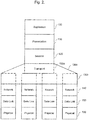
- FIG. 2 is a diagram showing an Open Systems Interconnection (OSI) protocol stack for the communication system illustrated in Figure 1 .
- layer 100 represents the application layer
- layer 110 represents the presentation layer
- layer 120 represents the session layer
- sub-layers 130a and 130b represent the transport layer
- layer 140 represents the network layer
- layer 150 represents the data link layer
- layer 160 represents the physical layer.
- the usual transport layer of the protocol stack as viewed by the OSI model, has been replaced with an upper transport sub-layer 130a and a plurality of lower transport sub-layers 130b.
- the lower transport sub-layers 130b relate to the inter-connection between the network devices and consist of multiple individual network links, each identified by a single network address at each end. In other words, the lower sub-layers 130b relate to the interconnection with the plurality of network links 40a- 40d shown in figure 1 .
- each individual network link uses a Transmission Control Protocol (TCP) connection, which reliably transfers data while limiting individual network link use according to round-trip-time, and bandwidth estimates as calculated from ACKs (acknowledgements) generated by a remote network device, as per normal TCP operation.
- TCP Transmission Control Protocol
- ACKs acknowledgements
- TCP is used to ensure the reliable transmission of data across each distinct network link while estimating round-trip time and bandwidth. While the format for TCP is unchanged, the TCP implementation itself is modified to allow access to the connection measurements and metrics.
- TCP TCP at this level
- TCP enhancements such as TCP Reno, Westwood or beyond
- TCP Reno, Westwood or beyond which may slightly improve individual connection performance without creating an overly large load on the network links
- the API to use TCP sockets is also well standardised and understood, and by substituting the TCP implementation, the "TCP meltdown problem" that occurs when stacking or tunnelling TCP through TCP can be avoided.
- a more optimal implementation may choose to integrate the upper transport sub-layer 130a and the plurality of lower transport sub-layers 130b in order to provide better efficiency, and lower footprint.
- the stack may be proprietary such that direct addition of the upper transport sub-layer 130a and the plurality of lower transport sub-layers 130b to an existing protocol stack is difficult.
- the arrangement of the implementation may be varied to embody the inverse-multiplexer within a Performance Enhancing Proxy (PEP) using split TCP as described in RFC3135.
- PEP Performance Enhancing Proxy
- a small modification is required to the TCP/IP protocol stack such that rather than forwarding data to a remote network device, it is delivered locally.
- This allows the TCP connection payloads to be accessed directly, free from overhead of packet headers and without TCP control packets having to traverse the network.
- the inverse-multiplexer 20 can then operate at an application level such that the data can be re-encapsulated and forwarded.
- An inverse multiplexing system as a whole requires a processing step at each of two communicating network devices.
- This processing step acts to transform original data into a format suitable for division between the plurality of utilised network links, directs the divided data through different networks, and then transforms the data back again to recover its original form at the receiving network device.
- the processing step has been standardised to bring the techniques of inverse multiplexing to a number of applications, such as low cost electrical Ethernet links on PC servers or workstations (e.g. IEEE 802.3ad), and inter-continental optical submarine communications cables.
- these current applications employ a plurality of stable network links where endpoints have fixed addresses, and which have been set up for the purpose of aggregation. As such, the characteristics of each network link changes slowly or can be considered stable under normal operating conditions. This means the processing step may easily be carried out and ensures the effect of aggregation is beneficial.
- the use of the different network links may be chosen to exploit this heterogeneity to an advantage.
- a routing system may be employed to utilise only the quickest network link such that a server and a mobile device can communicate with the lowest possible delay. If there are differing financial costs to transport data on each of the network links, the cheapest network link may be selected in order to save money.
- the duplication of data across network links is not precluded, and as discussed below, may actually provide advantages in transmission reliability. Under some circumstances the transmitting scheduler 24 may also decide that no data should to be sent at a particular time.
- the individual network links 40a -40d transport the data to the network link specific reception transceivers 58a-58d of the receiving inverse multiplexer 50. From the link specific reception transceivers 58a-58d, the data is sent to the network link specific reception windows 56a-56d. This process frees both the overall send window 22 and the link specific send windows 26a-26d of the transmitting inverse multiplexer 20 to make space for new input.
- the entry and exit point of each network link 40a -40d may include a unique address.
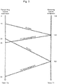
- FIG 3 is a timing diagram showing an example of a sequence of messages sent between the transmitting inverse multiplexer 20 and the receiving inverse multiplexer 50.
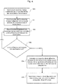
- Figure 4 shows a flow diagram of the processes carried out at the transmitting inverse multiplexer 20, while figure 5 shows the processes carried out by the receiving inverse multiplexer 50.
- the transmitting inverse multiplexer 20 is represented on the left, with its local time base represented by Ts, while the receiving inverse multiplexer 50 is represented on the right with its local time base represented by Tr.
- the two time-bases do need to be comparable such that they drift sufficiently slowly against each other such that no significant error is introduced to the calculations.
- the resolution of the clocks also needs to be a magnitude greater than the minimum expected network link latency that the system will experience.
- the receiving scheduler 54 Upon reception of data, the receiving scheduler 54 returns an acknowledgment to the transmitting scheduler 24. Together with the acknowledgement, the receiving scheduler 54 also sends additional information to the transmitting scheduler 24. The additional information sent depends on whether the data received is duplicate data. Once a data packet is moved to one of the network link specific reception windows 56a-56d from the link specific transceivers 58a-58d, the receiving scheduler 54 checks the remaining network link specific reception windows 56a-56d, and determines whether the received data packet is a duplicate (steps S11 and S12 of figure 5 ). This enables the receiving scheduler 54 to send the correct type of additional information to the transmitting scheduler 24.
- the additional information includes a network link identification and a time difference.
- the network link identification identifies the network link used for sending the original data.
- original data refers to the first received data in case of receiving duplicate data, it does not refer to the data received by the overall sending window 22 from the sever 10.
- the network link identifier is determined from the locally held records in the receiving scheduler 54.
- the time difference represents the positive elapsed time (or time delta) between the original reception of the data and the reception of the duplicate data. If the data is original, null values are used for the network link identification and time difference.
- the transmitting scheduler 24 receives the acknowledgement P 1 ACK and the additional information from the receiving scheduler 54 (step S02 of figure 4 ).
- the additional information sent with the acknowledgement P 1 ACK are null values, and so the transmitting scheduler 24 waits for the acknowledgement of reception of the duplicate data P 2 data, (step S03 of figure 4 ).
- the duplicate P 2 data is received over the second network link 40b.
- the receiving scheduler 54 determines that this data is duplicate data (i.e. the result to the query in step S12 is YES).
- the receiving scheduler 54 looks-up its record for the first reception of the data (e.g. reception of P 1 data), to retrieve the original reception time and network link used for the transmission of the original data (step S14).
- the receiving scheduler 54 then sends the acknowledgement P 2 ACK to the transmitting scheduler 24, which includes the additional information of the time difference (35ms) and the identification of the network link used to transmit the original P 1 data (the first network link 40a) (step S16).
- the receiving scheduler 54 then discards the duplicate data, P 2 data, (step S17).
- the second acknowledgment P 2 ACK is received from the receiving scheduler 54.
- the propagation delay is calculated using the received time difference (included with the acknowledgment P 2 ACK of the duplicate data) and the difference in the transmission times (times stamps) of the original and duplicate data, recorded by the transmitting scheduler 24.
- the 15ms propagation time delay can be used together with an estimate of network link bandwidths (estimated in a conventional manner such as packet-pair probing, accounting previously acknowledged data, using TCP metrics or being guided by physical layer supplied meta-data such as modulation and coding scheme selection or channel conditions) to choose more recent data in order to compensate for the difference in propagation delay. For example, if the first network link 40a is estimated to be operating at 1 Mbit/s and data has just been sent using the first network link 40a, the transmitting scheduler skips the next 15Kbits of the send window before selecting any data to be sent by the second network link 40b.
- the bandwidth can be conserved by prohibiting use of the slower second network link 40b until either the send window 22 has more than 15Kbits of queued data or the speed and quality of the second network link 40b improves to the extent that sending again becomes beneficial.
- one of a number of retransmission mechanisms may decide to utilise the second network link 40b instead of letting it idle.
- the transmitting scheduler 24 by processing the additional data sent with acknowledgement messages received from the receiving scheduler 54, together with the locally stored transmission times (time-stamps), can calculate the unidirectional propagation delay difference between different network links 40a - 40d. This does not require synchronised clocks at the server and mobile device. By comparing the send time-stamp of each data packet together with the time difference returned in acknowledgements (for duplicate data), the propagation delay times can be calculated. The propagation delay times are then used together with the conventionally collected bandwidth, round-trip-time estimates, and the calculated round-trip times of each data link, to send data deliberately out-of-order to account for differing network link delays. If the estimates are sufficiently accurate, data should then start to arrive in the expected order at the mobile device, thereby approaching perfect aggregation.
- the transmitting inverse multiplexer 20 can also use the gained metrics to minimise the size of the overall send window 22.
- the transmitting inverse multiplexer can calculate how large the overall send window 22 needs to be to enable data to be supplied, based upon the bandwidths and latencies. Limiting the size of the send window 22 prevents the addition of excess latency to the overall network link, and conversely placing a configured upper limit on that window size will also prevent heterogeneous network links whose delay is too great from being utilised to send new unique data.
- a network link it is preferable that there are mechanisms for deliberate retransmission of data on different network links, even if a network link is determined to be unreliable or slow. This is because retransmissions are needed to update and refresh the metrics used by the transmitting scheduler 24 to ensure that the transmitting scheduler 24 has a good model of the network link characteristics. For example, overtime an operating network link may improve from being the slowest network link to such an extent that it becomes the fastest or most reliable network link. Without some form of deliberate retransmission over, or limited use of, such a network link, the transmitting inverse multiplexer 20 is not able to determine the improvement in the network link, and can not make better use of the network link as it improves. Conversely, a network link can deteriorate overtime from being a good network link to being a poor network link, and so a method of detecting changes in the network link characteristics is very useful.
- One such retransmission mechanism is based on how much unacknowledged data is present on a network link.
- the amount of unacknowledged data is less than some preset value when a network link is ready for transmission, then some unacknowledged data from the inverse multiplexer's send window 22 is duplicated into the network link specific send window of that network link. This ensures that, rather than idling, under-utilised network links 40a - 40d are used to add redundancy to information transfer, while also collecting statistics on the network link itself. If sufficient traffic is present, the network links should automatically contain enough data that this type of deliberate duplication ceases, and the network links naturally operate in an aggregating manner.
- a second retransmission mechanism uses the estimated network link-specific propagation delay estimates, and round-trip time, to determine if either the acknowledgement for some sent data is late, or if sending the same data on a new network link may result in a faster transfer and earlier acknowledgement for the data. This ensures quick recovery from a failed network link, and also increases the rate at which metrics are collected for a network link whose properties start to diverge from the collected statistics.
- duplicate transmission and reception is not entirely bad. Although bandwidth is, in one sense, wasted due to duplicated data being sent and then discarded, in another sense the duplicated data allows valuable timing information to be gathered and used to provide feedback to improve the behaviour of the transmitting inverse multiplexer. It is the structure and content of the acknowledgements that allow not only for each network link's round-trip-time to be estimated, but also for the relative differences in unidirectional propagation delay for each network link to be computed.
- TCP protocol for the lower transport sub-layers 130b ensures the overall scheme operates on any TCP capable network, allowing the traversal of firewalls, routers, bridges and switches. TCP also ensures fair use of each network link with respect to other network users, whether they are using a simple TCP connection, or an aggregating connection as described.
- the inverse multiplexers 20, 50 are shown as separate devices to the server 10 and mobile device 60 in figure 1 .
- the transmitting inverse multiplexer 20 is mounted on an interface board (removably) installed within the server 10.
- the inverse multiplexer 50 is a hardware device that is removably connected to the mobile device 60 via a USB port, an "upgrade port" or any other suitable connector.
- the inverse multiplexers can be formed integrally as part of the hardware of the server 10 and the mobile device 60, or the inverse multiplexers 10, 50 may be embodied as a logical component integrated into the server and mobile device software or protocol stack.
- the number of network link specific send windows 26a - 26d and network link specific reception windows 56a-56d depends on the number of network links 40a-40d used. In situations in which only one network link 40 is available, the transmitting scheduler transmits all data over that single network link and requires only one reception window. In an alternative arrangement, particularly when the inverse multiplexers are embodied in software, the numbers of link specific transceivers 28a-28d, 58a - 58d and network link specific windows 26a-26d, 56a-56d may be adapted as the number of network links 40a-40d change and become available for data transmission.
- Some or all of the transmitting inverse multiplexer and the receiving inverse multiplexer may be implemented by a computer program using some form of processing apparatus.
- the invention therefore also extends to computer programs, particularly computer programs on or in a carrier, adapted for putting the invention into practice.
- the program may be in the form of source code, object code, a code intermediate to source code and object code such as in partially compiled form, or in any other form suitable for using in the implementation of the processes according to the invention.
- the carrier may be any entity or device capable of carrying the program.
- the carrier may comprise a storage medium, such as a ROM, for example a CD-ROM ornon-volatile semiconductor memories, or a magnetic recording medium, for example a floppy disc or a hard disc, or an optical recording medium.
- the carrier may be a transmissible carrier such as an electronic or optical signal which may be conveyed via electrical or optical cable or by radio or other means.
- the carrier may be an integrated circuit in which the program is embedded, or an integrated circuit adapted for performing the program steps, or for use in the performance of the relevant processes.
- Some or all of the transmitting inverse multiplexer and the receiving inverse multiplexer may be implemented in an Application Specific Integrated Circuit (ASIC) or a Field Programmable Gate Array (FPGA).
- ASIC Application Specific Integrated Circuit
- FPGA Field Programmable Gate Array
Landscapes
- Engineering & Computer Science (AREA)
- Computer Networks & Wireless Communication (AREA)
- Signal Processing (AREA)
- Quality & Reliability (AREA)
- Mobile Radio Communication Systems (AREA)
- Data Exchanges In Wide-Area Networks (AREA)
Claims (15)
- Verfahren zum Übertragen von Daten von einem ersten Netzwerkgerät (20) an ein zweites Netzwerkgerät (50) unter Verwendung einer Vielzahl von Netzwerkverbindungen (40a - 40d), wobei das Verfahren mit dem ersten Netzwerkgerät (20) umfasst:Senden (S00) erster Daten an das zweite Netzwerkgerät (50) über eine erste Netzwerkverbindung zu einer ersten Übertragungszeit;Senden (S01) zweiter Daten an das zweite Netzwerkgerät (50) über eine zweite Netzwerkverbindung zu einer zweiten Übertragungszeit;Empfangen (S02) eines Indikators für eine Zeitdifferenz zwischen dem Empfang der ersten Daten über die erste Netzwerkverbindung und dem Empfang der zweiten Daten über die zweite Netzwerkverbindung von dem zweiten Netzwerkgerät (50);Berechnen (S04) einer Laufzeitdifferenz zwischen der Zeit, die benötigt wurde, damit die ersten Daten das zweite Netzwerkgerät (50) über die erste Netzwerkverbindung und die zweiten Daten das zweite Netzwerkgerät (50) über die zweite Netzwerkverbindung erreichen unter Verwendung der empfangenen Zeitdifferenzindikation und der ersten und zweiten Übertragungszeiten;Bestimmen (S05) einer Netzwerkverbindungskonfiguration und einer Datenversandfolge unter Verwendung der berechneten Laufzeitdifferenz.
- Verfahren nach Anspruch 1, wobei die zweiten Daten eine erneute Übertragung der ersten Daten sind.
- Verfahren nach Anspruch 1, wobei die Laufzeitdifferenz durch Subtrahieren des Unterschieds zwischen der zweiten Übertragungszeit und der ersten Übertragungszeit von der empfangenen Zeitdifferenz berechnet wird.
- Verfahren nach Anspruch 1, wobei der Schritt des Bestimmens der Netzwerkverbindungskonfiguration und der Datenversandfolge ferner das Verwenden einer Abschätzung der Bandbreite der Netzwerkverbindungen umfasst.
- Verfahren nach Anspruch 1, ferner umfassend:Empfangen einer Bestätigung vom zweiten Netzwerkgerät (50), dass die ersten Daten empfangen wurden;Empfangen einer Bestätigung vom zweiten Netzwerkgerät (50), dass die zweiten Daten empfangen wurden;Berechnen der Umlaufzeit der ersten Netzwerkverbindung und der Umlaufzeit der zweiten Netzwerkverbindung, wobei der Schritt des Bestimmens der Netzwerkverbindungskonfiguration und der Datenversandfolge ferner das Verwenden der berechneten Umlaufzeiten umfasst.
- Verfahren nach Anspruch 5, wobei die zweite Bestätigung die Zeitdifferenzindikation umfasst.
- Verfahren nach Anspruch 1, ferner umfassend das Senden der Daten außerhalb der Folge über zwei oder mehr der mehreren Netzwerkverbindungen (40a - 40d).
- Verfahren nach Anspruch 1, ferner umfassend das Senden von duplizierten Daten über die mehreren Netzwerkverbindungen (40a - 40d).
- Verfahren zum Verarbeiten von Daten, die von einem ersten Netzwerkgerät (20) an ein zweites Netzwerkgerät (50) unter Verwendung mehrerer Netzwerkverbindungen (40a - 40d) gesendet wurden, wobei das Verfahren mit dem zweiten Netzwerkgerät (50) umfasst:Empfangen erster Daten vom ersten Netzwerkgerät (20) über eine erste Netzwerkverbindung zu einer ersten Empfangszeit;Empfangen zweiter Daten vom ersten Netzwerkgerät (20) über eine zweite Netzwerkverbindung zu einer zweiten Empfangszeit;Berechnen des Zeitunterschieds zwischen dem Empfangen der ersten Daten über die erste Netzwerkverbindung und dem Empfangen der zweiten Daten über die zweite Netzwerkverbindung; undSenden eines Indikators der berechneten Zeitdifferenz an das erste Netzwerkgerät (20).
- Verfahren nach Anspruch 9, wobei die zweiten Daten eine erneute Übertragung der ersten Daten sind.
- Verfahren nach Anspruch 10, ferner umfassend:nachfolgend auf den Empfang der ersten Daten, Senden einer Benachrichtigung an das erste Netzwerkgerät (20), dass die ersten Daten empfangen wurden;nachfolgend auf den Empfang der zweiten Daten, Senden einer Benachrichtigung an das erste Netzwerkgerät (20), dass die zweiten Daten empfangen wurden;wobei die zweite Benachrichtigung die Zeitdifferenzindikation umfasst.
- Inverser Multiplexer (20) umfassend
ein Gesamtsendefenster (22) zum Empfangen von Daten, die an ein entferntes Netzwerkgerät (50) übertragen werden sollen; und
einen Planer (24) zum Leiten der Daten von dem Gesamtsendefenster (22) über die mehreren Netzwerkverbindungen (40a - 40d) an das entfernte Netzwerkgerät (50);
wobei der Planer (24) eingerichtet ist zum:Senden erster Daten über eine erste Netzwerkverbindung zu einer ersten Übertragungszeit an das entfernte Netzwerkgerät (50);Senden zweiter Daten über eine zweite Netzwerkverbindung zu einer zweiten Übertragungszeit an das entfernte Netzwerkgerät (50);Empfangen eines Indikators einer Zeitdifferenz zwischen dem Empfang der ersten Daten über die erste Netzwerkverbindung und dem Empfang der zweiten Daten über die zweite Netzwerkverbindung vom entfernten Netzwerkgerät (50);Berechnen der Laufzeitdifferenz zwischen der ersten Netzwerkverbindung und der zweiten Netzwerkverbindung unter Verwendung der empfangenen Zeitdifferenzindikation und der ersten und zweiten Übertragungszeiten; undBestimmen einer Netzwerkverbindungskonfiguration und einer Datensendefolge unter Verwendung der berechneten Laufzeitdifferenz. - Netzwerkgerät (50) umfassend:einen ersten Empfänger (58a - 58d) zum Empfangen erster Daten von einem ersten Netzwerkgerät (20) über eine erste Netzwerkverbindung zu einer ersten Empfangszeit;einen zweiten Empfänger (58a - 58d) zum Empfangen zweiter Daten vom entfernten Netzwerkgerät (20) über eine zweite Netzwerkverbindung zu einer zweiten Empfangszeit;einen Berechner zum Berechnen der Zeitdifferenz zwischen dem Empfang der ersten Daten über die erste Netzwerkverbindung und dem Empfang der zweiten Daten über die zweite Netzwerkverbindung;einen Sender zum Senden eines Indikators der berechneten Zeitdifferenz an das entfernte Netzwerkgerät.
- Ein inverses Multiplexgerät umfassend einen inversen Multiplexer, wie in Anspruch 12 beansprucht, und ein Netzwerkgerät, wie in Anspruch 13 beansprucht.
- Computerprogrammprodukt umfassend einen Satz von Instruktionen, die, wenn sie durch ein programmierbares Gerät ausgeführt werden, das programmierbare Gerät veranlassen, ein Verfahren, wie es in einem der Ansprüche 1 bis 11 beansprucht ist, zu implementieren.
Priority Applications (3)
| Application Number | Priority Date | Filing Date | Title |
|---|---|---|---|
| EP14168191.6A EP2945416B1 (de) | 2014-05-13 | 2014-05-13 | Methode und Apparat für Übersendung von Daten über eine Mehrzahl von Netzwerken |
| PCT/EP2015/060472 WO2015173240A1 (en) | 2014-05-13 | 2015-05-12 | Method and apparatus for transmission of data over a plurality of networks |
| US14/710,396 US20150334630A1 (en) | 2014-05-13 | 2015-05-12 | Method and apparatus for transmission of data over a plurality of networks |
Applications Claiming Priority (1)
| Application Number | Priority Date | Filing Date | Title |
|---|---|---|---|
| EP14168191.6A EP2945416B1 (de) | 2014-05-13 | 2014-05-13 | Methode und Apparat für Übersendung von Daten über eine Mehrzahl von Netzwerken |
Publications (2)
| Publication Number | Publication Date |
|---|---|
| EP2945416A1 EP2945416A1 (de) | 2015-11-18 |
| EP2945416B1 true EP2945416B1 (de) | 2018-04-11 |
Family
ID=50792358
Family Applications (1)
| Application Number | Title | Priority Date | Filing Date |
|---|---|---|---|
| EP14168191.6A Active EP2945416B1 (de) | 2014-05-13 | 2014-05-13 | Methode und Apparat für Übersendung von Daten über eine Mehrzahl von Netzwerken |
Country Status (3)
| Country | Link |
|---|---|
| US (1) | US20150334630A1 (de) |
| EP (1) | EP2945416B1 (de) |
| WO (1) | WO2015173240A1 (de) |
Families Citing this family (8)
| Publication number | Priority date | Publication date | Assignee | Title |
|---|---|---|---|---|
| US20150373075A1 (en) * | 2014-06-23 | 2015-12-24 | Radia Perlman | Multiple network transport sessions to provide context adaptive video streaming |
| CN109417493B (zh) | 2016-07-01 | 2023-01-20 | 瑞典爱立信有限公司 | 往返时间偏差控制方法和布置 |
| CN109417830B (zh) * | 2016-08-08 | 2021-10-15 | 华为技术有限公司 | 数据传输方法、发送端设备及接收端设备 |
| EP3577912B1 (de) * | 2017-02-01 | 2023-05-24 | Nokia Technologies Oy | Bestimmung des zugangsslots für kommunikation auf einer funkschnittstelle |
| US10969822B2 (en) | 2017-02-15 | 2021-04-06 | International Business Machines Corporation | Reducing time of day latency variation in a multi processor system |
| US10324491B2 (en) * | 2017-02-15 | 2019-06-18 | International Business Machines Corporation | Reducing time of day latency variation in a multi-processor system |
| CN111669285A (zh) * | 2020-05-08 | 2020-09-15 | 广州微算互联信息技术有限公司 | 一种网络检测数据的处理方法、系统和存储介质 |
| EP4297460A1 (de) | 2022-06-23 | 2023-12-27 | EXFO Oy | Verfahren und vorrichtung zur identitätssammlung |
Family Cites Families (7)
| Publication number | Priority date | Publication date | Assignee | Title |
|---|---|---|---|---|
| US8290034B2 (en) | 1998-12-21 | 2012-10-16 | Zin Stai Pte. In, Llc | Video transmission and display including bit-wise sub-sampling video compression |
| US7327676B2 (en) * | 2001-10-11 | 2008-02-05 | Nippon Telegraph And Telephone Corporation | Data transmission control method, program therefor and data transmission unit using the same |
| US8098648B2 (en) * | 2004-01-09 | 2012-01-17 | Nec Corporation | Load distributing method |
| WO2005079534A2 (en) * | 2004-02-19 | 2005-09-01 | Georgia Tech Research Corporation | Systems and methods for parallel communication |
| EP1608112B1 (de) * | 2004-06-14 | 2011-02-23 | Broadcom Corporation | Kompensation und Messung der Differentiellen Verzögerung in gebundenen Systemen |
| EP2001174A4 (de) * | 2006-03-29 | 2010-04-21 | Nec Corp | Kommunikationsverfahren, knoten und steuerprogramm |
| US9537612B2 (en) * | 2013-12-09 | 2017-01-03 | Apple Inc. | Restrictions on transmissions of control plane data with carrier aggregation |
-
2014
- 2014-05-13 EP EP14168191.6A patent/EP2945416B1/de active Active
-
2015
- 2015-05-12 US US14/710,396 patent/US20150334630A1/en not_active Abandoned
- 2015-05-12 WO PCT/EP2015/060472 patent/WO2015173240A1/en not_active Ceased
Non-Patent Citations (1)
| Title |
|---|
| None * |
Also Published As
| Publication number | Publication date |
|---|---|
| EP2945416A1 (de) | 2015-11-18 |
| WO2015173240A1 (en) | 2015-11-19 |
| US20150334630A1 (en) | 2015-11-19 |
Similar Documents
| Publication | Publication Date | Title |
|---|---|---|
| EP2945416B1 (de) | Methode und Apparat für Übersendung von Daten über eine Mehrzahl von Netzwerken | |
| US9253015B2 (en) | Transparent proxy architecture for multi-path data connections | |
| Abed et al. | Exploration and evaluation of traditional TCP congestion control techniques | |
| US20050213586A1 (en) | System and method to increase network throughput | |
| EP2232791B1 (de) | Abstand zwischen tcp-paketen | |
| EP1227639A2 (de) | Netzdienst für adaptive Mobile Anwendungen | |
| Henderson | Networking over next-generation satellite systems | |
| WO2021022383A1 (en) | Systems and methods for managing data packet communications | |
| EP4572393A1 (de) | Verfahren und vorrichtung zur übertragung eines protokolldateneinheitssatzes | |
| Abdelsalam et al. | Steady-state performance evaluation of Linux TCPs versus TCP wave over leaky satellite links | |
| Ivanovich et al. | On TCP performance enhancing proxies in a wireless environment | |
| Kim et al. | Enhancing TCP end-to-end performance in millimeter-wave communications | |
| Hegde et al. | FAST TCP in high-speed networks: An experimental study | |
| Abed et al. | Architecture And Functional Structure Of Transmission Control Protocol Over Various Networks Applications | |
| Mishra et al. | Enhanced reliability in mobility scenarios using multi-connectivity with packet duplication for next-generation networks | |
| Morelli et al. | Performance evaluation of transport protocols in tactical network environments | |
| CN114745273A (zh) | Tcp加速代理方法、装置、卫星地面站及可读存储介质 | |
| Cano-Garcia et al. | Experimental analysis and characterization of packet delay in UMTS networks | |
| Liao et al. | A multi-path mechanism for reliable VoIP transmission over wireless networks | |
| CN116708281A (zh) | 一种基于mptcp协议的gnss网络基准站系统数据调度方法 | |
| Han et al. | A Novel UDT‐Based Transfer Speed‐Up Protocol for Fog Computing | |
| Wang et al. | Concurrent multipath transfer protocol used in ad hoc networks | |
| Lopes | Connectivity Gateway for Heterogeneous Environments | |
| Nikitinskiy et al. | Analyzing the possibility of applying asymmetric transport protocols in terms of software defined networks | |
| Yi | Cross-Layer Telemetry and Optimization for Real-Time Interactive Applications in 5G Networks |
Legal Events
| Date | Code | Title | Description |
|---|---|---|---|
| PUAI | Public reference made under article 153(3) epc to a published international application that has entered the european phase |
Free format text: ORIGINAL CODE: 0009012 |
|
| AK | Designated contracting states |
Kind code of ref document: A1 Designated state(s): AL AT BE BG CH CY CZ DE DK EE ES FI FR GB GR HR HU IE IS IT LI LT LU LV MC MK MT NL NO PL PT RO RS SE SI SK SM TR |
|
| AX | Request for extension of the european patent |
Extension state: BA ME |
|
| 17P | Request for examination filed |
Effective date: 20160518 |
|
| RBV | Designated contracting states (corrected) |
Designated state(s): AL AT BE BG CH CY CZ DE DK EE ES FI FR GB GR HR HU IE IS IT LI LT LU LV MC MK MT NL NO PL PT RO RS SE SI SK SM TR |
|
| R17P | Request for examination filed (corrected) |
Effective date: 20160518 |
|
| GRAP | Despatch of communication of intention to grant a patent |
Free format text: ORIGINAL CODE: EPIDOSNIGR1 |
|
| INTG | Intention to grant announced |
Effective date: 20171025 |
|
| GRAS | Grant fee paid |
Free format text: ORIGINAL CODE: EPIDOSNIGR3 |
|
| GRAA | (expected) grant |
Free format text: ORIGINAL CODE: 0009210 |
|
| AK | Designated contracting states |
Kind code of ref document: B1 Designated state(s): AL AT BE BG CH CY CZ DE DK EE ES FI FR GB GR HR HU IE IS IT LI LT LU LV MC MK MT NL NO PL PT RO RS SE SI SK SM TR |
|
| REG | Reference to a national code |
Ref country code: GB Ref legal event code: FG4D |
|
| REG | Reference to a national code |
Ref country code: CH Ref legal event code: EP |
|
| REG | Reference to a national code |
Ref country code: AT Ref legal event code: REF Ref document number: 989291 Country of ref document: AT Kind code of ref document: T Effective date: 20180415 |
|
| REG | Reference to a national code |
Ref country code: IE Ref legal event code: FG4D |
|
| REG | Reference to a national code |
Ref country code: DE Ref legal event code: R096 Ref document number: 602014023588 Country of ref document: DE |
|
| REG | Reference to a national code |
Ref country code: NL Ref legal event code: MP Effective date: 20180411 |
|
| REG | Reference to a national code |
Ref country code: LT Ref legal event code: MG4D |
|
| REG | Reference to a national code |
Ref country code: FR Ref legal event code: PLFP Year of fee payment: 5 |
|
| PG25 | Lapsed in a contracting state [announced via postgrant information from national office to epo] |
Ref country code: NL Free format text: LAPSE BECAUSE OF FAILURE TO SUBMIT A TRANSLATION OF THE DESCRIPTION OR TO PAY THE FEE WITHIN THE PRESCRIBED TIME-LIMIT Effective date: 20180411 |
|
| PG25 | Lapsed in a contracting state [announced via postgrant information from national office to epo] |
Ref country code: BG Free format text: LAPSE BECAUSE OF FAILURE TO SUBMIT A TRANSLATION OF THE DESCRIPTION OR TO PAY THE FEE WITHIN THE PRESCRIBED TIME-LIMIT Effective date: 20180711 Ref country code: NO Free format text: LAPSE BECAUSE OF FAILURE TO SUBMIT A TRANSLATION OF THE DESCRIPTION OR TO PAY THE FEE WITHIN THE PRESCRIBED TIME-LIMIT Effective date: 20180711 Ref country code: LT Free format text: LAPSE BECAUSE OF FAILURE TO SUBMIT A TRANSLATION OF THE DESCRIPTION OR TO PAY THE FEE WITHIN THE PRESCRIBED TIME-LIMIT Effective date: 20180411 Ref country code: FI Free format text: LAPSE BECAUSE OF FAILURE TO SUBMIT A TRANSLATION OF THE DESCRIPTION OR TO PAY THE FEE WITHIN THE PRESCRIBED TIME-LIMIT Effective date: 20180411 Ref country code: SE Free format text: LAPSE BECAUSE OF FAILURE TO SUBMIT A TRANSLATION OF THE DESCRIPTION OR TO PAY THE FEE WITHIN THE PRESCRIBED TIME-LIMIT Effective date: 20180411 Ref country code: AL Free format text: LAPSE BECAUSE OF FAILURE TO SUBMIT A TRANSLATION OF THE DESCRIPTION OR TO PAY THE FEE WITHIN THE PRESCRIBED TIME-LIMIT Effective date: 20180411 Ref country code: ES Free format text: LAPSE BECAUSE OF FAILURE TO SUBMIT A TRANSLATION OF THE DESCRIPTION OR TO PAY THE FEE WITHIN THE PRESCRIBED TIME-LIMIT Effective date: 20180411 Ref country code: PL Free format text: LAPSE BECAUSE OF FAILURE TO SUBMIT A TRANSLATION OF THE DESCRIPTION OR TO PAY THE FEE WITHIN THE PRESCRIBED TIME-LIMIT Effective date: 20180411 |
|
| PG25 | Lapsed in a contracting state [announced via postgrant information from national office to epo] |
Ref country code: LV Free format text: LAPSE BECAUSE OF FAILURE TO SUBMIT A TRANSLATION OF THE DESCRIPTION OR TO PAY THE FEE WITHIN THE PRESCRIBED TIME-LIMIT Effective date: 20180411 Ref country code: RS Free format text: LAPSE BECAUSE OF FAILURE TO SUBMIT A TRANSLATION OF THE DESCRIPTION OR TO PAY THE FEE WITHIN THE PRESCRIBED TIME-LIMIT Effective date: 20180411 Ref country code: HR Free format text: LAPSE BECAUSE OF FAILURE TO SUBMIT A TRANSLATION OF THE DESCRIPTION OR TO PAY THE FEE WITHIN THE PRESCRIBED TIME-LIMIT Effective date: 20180411 Ref country code: GR Free format text: LAPSE BECAUSE OF FAILURE TO SUBMIT A TRANSLATION OF THE DESCRIPTION OR TO PAY THE FEE WITHIN THE PRESCRIBED TIME-LIMIT Effective date: 20180712 |
|
| REG | Reference to a national code |
Ref country code: CH Ref legal event code: PL |
|
| REG | Reference to a national code |
Ref country code: AT Ref legal event code: MK05 Ref document number: 989291 Country of ref document: AT Kind code of ref document: T Effective date: 20180411 |
|
| PG25 | Lapsed in a contracting state [announced via postgrant information from national office to epo] |
Ref country code: PT Free format text: LAPSE BECAUSE OF FAILURE TO SUBMIT A TRANSLATION OF THE DESCRIPTION OR TO PAY THE FEE WITHIN THE PRESCRIBED TIME-LIMIT Effective date: 20180813 |
|
| REG | Reference to a national code |
Ref country code: DE Ref legal event code: R097 Ref document number: 602014023588 Country of ref document: DE |
|
| REG | Reference to a national code |
Ref country code: BE Ref legal event code: MM Effective date: 20180531 |
|
| PG25 | Lapsed in a contracting state [announced via postgrant information from national office to epo] |
Ref country code: EE Free format text: LAPSE BECAUSE OF FAILURE TO SUBMIT A TRANSLATION OF THE DESCRIPTION OR TO PAY THE FEE WITHIN THE PRESCRIBED TIME-LIMIT Effective date: 20180411 Ref country code: CZ Free format text: LAPSE BECAUSE OF FAILURE TO SUBMIT A TRANSLATION OF THE DESCRIPTION OR TO PAY THE FEE WITHIN THE PRESCRIBED TIME-LIMIT Effective date: 20180411 Ref country code: RO Free format text: LAPSE BECAUSE OF FAILURE TO SUBMIT A TRANSLATION OF THE DESCRIPTION OR TO PAY THE FEE WITHIN THE PRESCRIBED TIME-LIMIT Effective date: 20180411 Ref country code: MC Free format text: LAPSE BECAUSE OF FAILURE TO SUBMIT A TRANSLATION OF THE DESCRIPTION OR TO PAY THE FEE WITHIN THE PRESCRIBED TIME-LIMIT Effective date: 20180411 Ref country code: SK Free format text: LAPSE BECAUSE OF FAILURE TO SUBMIT A TRANSLATION OF THE DESCRIPTION OR TO PAY THE FEE WITHIN THE PRESCRIBED TIME-LIMIT Effective date: 20180411 Ref country code: AT Free format text: LAPSE BECAUSE OF FAILURE TO SUBMIT A TRANSLATION OF THE DESCRIPTION OR TO PAY THE FEE WITHIN THE PRESCRIBED TIME-LIMIT Effective date: 20180411 Ref country code: DK Free format text: LAPSE BECAUSE OF FAILURE TO SUBMIT A TRANSLATION OF THE DESCRIPTION OR TO PAY THE FEE WITHIN THE PRESCRIBED TIME-LIMIT Effective date: 20180411 |
|
| PLBE | No opposition filed within time limit |
Free format text: ORIGINAL CODE: 0009261 |
|
| STAA | Information on the status of an ep patent application or granted ep patent |
Free format text: STATUS: NO OPPOSITION FILED WITHIN TIME LIMIT |
|
| REG | Reference to a national code |
Ref country code: IE Ref legal event code: MM4A |
|
| PG25 | Lapsed in a contracting state [announced via postgrant information from national office to epo] |
Ref country code: SM Free format text: LAPSE BECAUSE OF FAILURE TO SUBMIT A TRANSLATION OF THE DESCRIPTION OR TO PAY THE FEE WITHIN THE PRESCRIBED TIME-LIMIT Effective date: 20180411 Ref country code: IT Free format text: LAPSE BECAUSE OF FAILURE TO SUBMIT A TRANSLATION OF THE DESCRIPTION OR TO PAY THE FEE WITHIN THE PRESCRIBED TIME-LIMIT Effective date: 20180411 Ref country code: LI Free format text: LAPSE BECAUSE OF NON-PAYMENT OF DUE FEES Effective date: 20180531 Ref country code: CH Free format text: LAPSE BECAUSE OF NON-PAYMENT OF DUE FEES Effective date: 20180531 |
|
| 26N | No opposition filed |
Effective date: 20190114 |
|
| PG25 | Lapsed in a contracting state [announced via postgrant information from national office to epo] |
Ref country code: LU Free format text: LAPSE BECAUSE OF NON-PAYMENT OF DUE FEES Effective date: 20180513 |
|
| PG25 | Lapsed in a contracting state [announced via postgrant information from national office to epo] |
Ref country code: IE Free format text: LAPSE BECAUSE OF NON-PAYMENT OF DUE FEES Effective date: 20180513 |
|
| PG25 | Lapsed in a contracting state [announced via postgrant information from national office to epo] |
Ref country code: SI Free format text: LAPSE BECAUSE OF FAILURE TO SUBMIT A TRANSLATION OF THE DESCRIPTION OR TO PAY THE FEE WITHIN THE PRESCRIBED TIME-LIMIT Effective date: 20180411 Ref country code: BE Free format text: LAPSE BECAUSE OF NON-PAYMENT OF DUE FEES Effective date: 20180531 |
|
| PG25 | Lapsed in a contracting state [announced via postgrant information from national office to epo] |
Ref country code: MT Free format text: LAPSE BECAUSE OF NON-PAYMENT OF DUE FEES Effective date: 20180513 |
|
| PG25 | Lapsed in a contracting state [announced via postgrant information from national office to epo] |
Ref country code: TR Free format text: LAPSE BECAUSE OF FAILURE TO SUBMIT A TRANSLATION OF THE DESCRIPTION OR TO PAY THE FEE WITHIN THE PRESCRIBED TIME-LIMIT Effective date: 20180411 |
|
| PG25 | Lapsed in a contracting state [announced via postgrant information from national office to epo] |
Ref country code: HU Free format text: LAPSE BECAUSE OF FAILURE TO SUBMIT A TRANSLATION OF THE DESCRIPTION OR TO PAY THE FEE WITHIN THE PRESCRIBED TIME-LIMIT; INVALID AB INITIO Effective date: 20140513 Ref country code: MK Free format text: LAPSE BECAUSE OF NON-PAYMENT OF DUE FEES Effective date: 20180411 Ref country code: CY Free format text: LAPSE BECAUSE OF FAILURE TO SUBMIT A TRANSLATION OF THE DESCRIPTION OR TO PAY THE FEE WITHIN THE PRESCRIBED TIME-LIMIT Effective date: 20180411 |
|
| PG25 | Lapsed in a contracting state [announced via postgrant information from national office to epo] |
Ref country code: IS Free format text: LAPSE BECAUSE OF FAILURE TO SUBMIT A TRANSLATION OF THE DESCRIPTION OR TO PAY THE FEE WITHIN THE PRESCRIBED TIME-LIMIT Effective date: 20180811 |
|
| PGFP | Annual fee paid to national office [announced via postgrant information from national office to epo] |
Ref country code: DE Payment date: 20250528 Year of fee payment: 12 |
|
| PGFP | Annual fee paid to national office [announced via postgrant information from national office to epo] |
Ref country code: FR Payment date: 20250526 Year of fee payment: 12 |
|
| PGFP | Annual fee paid to national office [announced via postgrant information from national office to epo] |
Ref country code: GB Payment date: 20260313 Year of fee payment: 13 |