EP2945421A1 - Verfahren, vorrichtung und netzwerkvorrichtung zur erfassung von nachbarschaftsbeziehungen zwischen netzwerkknoten - Google Patents
Verfahren, vorrichtung und netzwerkvorrichtung zur erfassung von nachbarschaftsbeziehungen zwischen netzwerkknoten Download PDFInfo
- Publication number
- EP2945421A1 EP2945421A1 EP13874607.8A EP13874607A EP2945421A1 EP 2945421 A1 EP2945421 A1 EP 2945421A1 EP 13874607 A EP13874607 A EP 13874607A EP 2945421 A1 EP2945421 A1 EP 2945421A1
- Authority
- EP
- European Patent Office
- Prior art keywords
- message
- neighbor relationship
- network
- network node
- network nodes
- Prior art date
- Legal status (The legal status is an assumption and is not a legal conclusion. Google has not performed a legal analysis and makes no representation as to the accuracy of the status listed.)
- Granted
Links
- 238000000034 method Methods 0.000 title claims abstract description 88
- 238000012790 confirmation Methods 0.000 claims description 23
- 230000008569 process Effects 0.000 description 40
- 230000011664 signaling Effects 0.000 description 23
- 238000010586 diagram Methods 0.000 description 22
- 230000003993 interaction Effects 0.000 description 8
- 238000012546 transfer Methods 0.000 description 8
- 230000009286 beneficial effect Effects 0.000 description 4
- 230000006870 function Effects 0.000 description 3
- 230000007774 longterm Effects 0.000 description 2
- 238000005457 optimization Methods 0.000 description 2
- 238000005516 engineering process Methods 0.000 description 1
- GVVPGTZRZFNKDS-JXMROGBWSA-N geranyl diphosphate Chemical compound CC(C)=CCC\C(C)=C\CO[P@](O)(=O)OP(O)(O)=O GVVPGTZRZFNKDS-JXMROGBWSA-N 0.000 description 1
- 238000012986 modification Methods 0.000 description 1
- 230000004048 modification Effects 0.000 description 1
- 230000003287 optical effect Effects 0.000 description 1
- 238000012545 processing Methods 0.000 description 1
Images



Classifications
-
- H—ELECTRICITY
- H04—ELECTRIC COMMUNICATION TECHNIQUE
- H04W—WIRELESS COMMUNICATION NETWORKS
- H04W36/00—Hand-off or reselection arrangements
- H04W36/0005—Control or signalling for completing the hand-off
- H04W36/0055—Transmission or use of information for re-establishing the radio link
- H04W36/0061—Transmission or use of information for re-establishing the radio link of neighbour cell information
-
- H—ELECTRICITY
- H04—ELECTRIC COMMUNICATION TECHNIQUE
- H04W—WIRELESS COMMUNICATION NETWORKS
- H04W68/00—User notification, e.g. alerting and paging, for incoming communication, change of service or the like
- H04W68/02—Arrangements for increasing efficiency of notification or paging channel
-
- H—ELECTRICITY
- H04—ELECTRIC COMMUNICATION TECHNIQUE
- H04W—WIRELESS COMMUNICATION NETWORKS
- H04W24/00—Supervisory, monitoring or testing arrangements
- H04W24/02—Arrangements for optimising operational condition
Definitions
- the present invention relates to the field of communications technologies, and in particular, to a method and an apparatus for obtaining an neighbor relationship between network nodes, and a network device.
- LTE Long Term Evolution access network
- 3GPP 3rd Generation Partnership Project
- SGW Serving Gateway
- the MME pages users in all eNodeB base stations in a tracking area list (Tracking Area List, TA LIST) area in which the user equipment is located last time, where the TA LIST includes one or more tracking areas (Tracking Area, TA) that correspond to dozens or hundreds of eNodeBs.
- TA LIST Tracking Area List
- the MME learns information about an eNodeB on which a user camps last time, information about a TA on which the user camps last time, and information about a TA List on which the user camps last time. Therefore, the MME may also page a user in the eNodeB on which the user camps last time or in the TA on which the user camps last time, to reduce a quantity of eNodeBs involved in the paging.
- UMTS Universal Mobile Telecommunications System
- UMTS Universal Mobile Telecommunications System
- a paging success rate in a cell on which user equipment camps last time is about 65%
- a paging success rate in a cell on which a user camps last time and a neighboring cell of the cell is about 90%.
- Cell coverage areas of eNodeBs of the UMTS and LTE are similar.
- the MME pages a user only in a range of an eNodeB on which the user camps last time, and a success rate may only be 65% to 70%.
- the MME pages a user in a small range, namely, the eNodeB on which the user camps last time and a neighboring eNodeB of the eNodeB, and a success rate being more than 90% may be obtained, which is a good trade-off between a paging range and a paging success rate.
- a technical problem to be resolved in the present invention is to provide a method and an apparatus for obtaining a neighbor relationship between network nodes, and a network device, so that a wireless network learns a neighbor relationship between network nodes, thereby improving efficiency of performing a service between neighboring network nodes.
- an embodiment of the present invention provides a method for obtaining a neighbor relationship between network nodes, including:
- the message is any one of the following: a message used for requesting handover of a network node serving user equipment, a message carrying extension information, and a user-defined message.
- the parsing the message, to obtain a neighbor relationship between at least two network nodes involved in the message includes:
- the parsing the message, to obtain a neighbor relationship between at least two network nodes involved in the message includes:
- the message further carries an identifier used for indicating that the message is a neighbor relationship reporting message.
- the parsing the message, to obtain a neighbor relationship between at least two network nodes involved in the message includes:
- the method further includes:
- an embodiment of the present invention provides an apparatus for obtaining a neighbor relationship between network nodes, including:
- the message is any one of the following: a message used for requesting handover of a network node serving user equipment, a message carrying extension information, and a user-defined message.
- the first obtaining unit includes:
- the first obtaining unit includes:
- the message further carries an identifier used for indicating that the message is a neighbor relationship reporting message.
- the first obtaining unit includes:
- the apparatus further includes:
- an embodiment of the present invention provides a network device, including: an input apparatus, an output apparatus, a memory, and a processor, where the processor performs the following steps:
- the message is any one of the following: a message used for requesting handover of a network node serving user equipment, a message carrying extension information, and a user-defined message.
- the step, performed by the processor, of parsing the message, to obtain a neighbor relationship between at least two network nodes involved in the message includes:
- the step, performed by the processor, of parsing the message, to obtain a neighbor relationship between at least two network nodes involved in the message includes:
- the message further carries an identifier used for indicating that the message is a neighbor relationship reporting message.
- the step, performed by the processor, of parsing the message, to obtain a neighbor relationship between at least two network nodes involved in the message includes:
- the processor after the processor performs the step of parsing the message, to obtain a neighbor relationship between at least two network nodes involved in the message, the processor further performs the following step:
- a core network learns a neighbor relationship between network nodes, and efficiency of performing a service between neighboring network nodes may be improved by using the neighbor relationship.
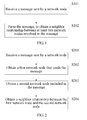
- FIG. 1 is a method flowchart of an embodiment of a method for obtaining a neighbor relationship between network nodes according to the present invention. As shown in FIG. 1 , the method includes:
- a wireless access network and a core network exchanges related messages.
- the core network receives a message sent by a network node in the wireless access network, for example, in an LTE network, a network element of the core network, namely, an MME, receives a message sent by an eNodeB.
- the message may be any one of the following: a message used for requesting handover of a network node serving user equipment, a message carrying extension information, and a user-defined message.
- the message includes at least one network node to which the network node that sends the message points or includes the network node that sends the message and at least one other network node, where the network node may be identified by using an identification code.
- the core network parses the message. If the message is a message used for requesting handover of a network node serving user equipment, first, the core network obtains an identification code, included in the message, of one network node to which handover points, and then obtains an identification code of the other network node that sends the message. Because handover definitely occurs between two neighboring network nodes, the core network obtains a neighbor relationship between the two network nodes.
- the message is a message carrying extension information, it indicates that the message is used for performing configuration on neighboring network nodes, or if the extension information further carries an identifier, it indicates that the message is used for reporting the neighbor relationship; the neighbor relationship between the at least two network nodes may be obtained from the identification codes, included in the extension information of the message, of the at least two network nodes. If the message is a user-defined message, it indicates that the message is used for reporting the neighbor relationship, and the message includes at least two network nodes involved in the neighbor relationship; the core network obtains the neighbor relationship between the at least two network nodes.
- the core network gradually learns neighbor relationships between network nodes in an entire network, and efficiency of performing a service between neighboring network nodes may be improved by using the neighbor relationship, for example, learning the neighbor relationship between the network nodes is very beneficial to optimization of a paging range.
- the MME pages a user only in a range of an eNodeB on which the user camps last time, and a success rate may only be 65% to 70%.
- a quantity of eNodeBs involved in the paging is still large.
- the MME pages a user in a relatively small range, namely, the eNodeB on which the user camps last time and a neighboring eNodeB of the eNodeB, and a success rate being more than 90% may be obtained, which is a good trade-off between a paging range and a paging success rate.
- Learning a neighbor relationship between network nodes is also very beneficial to improving efficiency of other services involving neighboring network nodes.
- a core network learns a neighbor relationship between network nodes, and efficiency of performing a service between neighboring network nodes may be improved by using the neighbor relationship.
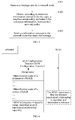
- FIG. 2 is a method flowchart of a specific implementation manner of an embodiment of a method for obtaining a neighbor relationship between network nodes according to the present invention. As shown in FIG. 2 , the method includes:
- the message sent by the first network node is received, where the message includes the second network node to which the network node that sends the message points, and the network node may be identified by using an identification code.
- the first network node that sends the message may be a source network node, and the second network node included in the message is a destination network node.
- the first network node that sends the message may be a destination network node, and the second network node included in the message is a source network node.
- a core network After receiving the message, first, a core network obtains an identification code, included in the message, of the second network node to which handover points, and then obtains an identification code of the first network node that sends the message. Because handover definitely occurs between two neighboring network nodes, the core network obtains an neighbor relationship between the two network nodes.
- a core network element is required to automatically learn the neighbor relationship between the network nodes according to an existing process without the need of proprietary extension of a message or a proprietary message.
- An LTE network is used as an example for description: in the LTE network, the 3GPP protocol specifies that user equipment in a connected state needs to perform handover (HANDOVER) when moving between eNodeBs.
- HANDOVER handover
- the MME may learn a relationship between neighboring eNodeBs. With the movement of a large quantity of users in a connected state, the MME may gradually learn neighbor relationships between eNodeBs in an entire network.
- the GPP defines two handover scenarios:
- a network element of the core network namely, an MME, learns the neighbor relationship between the eNodeBs in the two scenarios respectively.
- the first scenario the neighbor relationship between the eNodeBs is learnt based on an X2-BASED HANDOVER process.
- the 3GPP 23.401 defines that the X2-BASED HANDOVER process occurs when a terminal in a connected state moves between neighboring eNodeBs having the X2 interfaces if the MME is not changed.
- a destination eNodeB sends "Path Switch Request” signaling to the MME to initiate a handover process.
- a process in which the MME learns the neighbor relationship between the eNodeBs in the first scenario is as follows: as shown in a schematic diagram based on an X2-BASED HANDOVER process in FIG. 3 , a "Path Switch Request" message definitely carries a "Source MME UE S1AP ID” information element, and the MME may find, according to a numerical value of the information element, a context of an "MME UE S1AP ID" having a same numerical value.
- the context stores information about user equipment performing handover, an "eNodeB Address in Use" in the context is an IP address of a source eNodeB, and the MME finds an identification code of the source eNodeB according to the IP address.
- the MME may use the eNodeB that sends the signaling as the destination eNodeB, and find an identification code of the destination eNodeB according to the IP address.
- the MME knows that the handover process definitely occurs between two neighboring eNodeBs, and therefore, the MME learns a neighbor relationship between the source eNodeB and the destination eNodeB.
- the second scenario the neighbor relationship between the eNodeBs is learnt based on an S1-BASED HANDOVER process.
- the 3GPP 23.401 defines that the S1-BASED HANDOVER process occurs when the terminal in the connected state cannot move between neighboring eNodeBs in the X2-BASED HANDOVER (when the user in the connected state moves between two eNodeBs, no X2 interface exists between the eNodeBs, or handover by using an X2 interface cannot be performed). Both the MME and an SGW may be changed (referring to description of a 3GPP 23.401 S1-BASED HANDOVER message process).
- the source eNodeB sends "Handover Required" signaling to the MME to initiate the S1-BASED HANDOVER process.
- S1-BASED HANDOVER between the MMEs (Inter-MME)
- MMEs accessed by the neighboring eNodeBs are different, cross-MME paging cannot be performed when paging is performed, and therefore, there is no need to consider learning of the neighbor relationship between the eNodeBs in this scenario;
- the S1-BASED HANDOVER in the MME Intra-MME
- the neighbor relationship between the eNodeBs between which the S1-BASED HANDOVER occurs needs to be learnt.
- a process in which the MME learns the neighbor relationship between the eNodeBs in the second scenario is as follows: as shown in a schematic diagram based on the S1-BASED HANDOVER process in FIG. 4 , the "Handover Required" signaling is from the source eNodeB, and after receiving the signaling, the MME may use the eNodeB that sends the signaling as the source eNodeB, and find the identification code of the source eNodeB according to the IP address; while, a destination identification code in the "Handover Required" signaling is the identification code of the destination eNodeB.
- the MME knows that the handover process definitely occurs between two neighboring eNodeBs, and therefore, the MME learns an neighbor relationship between the source eNodeB and the destination eNodeB.
- a core network may learn an neighbor relationship between network nodes by using an existing process of sending a handover message of a network node serving user equipment and without the need of a special message reporting process, and efficiency of performing a service between neighboring network nodes may be improved by using the neighbor relationship.
- FIG. 5 is a method flowchart of another specific implementation manner of an embodiment of a method for obtaining a neighbor relationship between network nodes according to the present invention. As shown in FIG. 5 , the method includes:
- a standard interface message is used, the message is a message carrying extension information, and it indicates that the message is used for performing configuration on neighboring network nodes; or if the extension information further carries an identifier used for indicating that the message is a neighbor relationship reporting message, a neighbor relationship between at least two network nodes may be obtained from identification codes, included in the extension information of the message, of the at least two network nodes.
- an original protocol between a core network and a wireless network does not have a confirmation message, it is not necessary to specially add a proprietary message to implement a confirmation function, that is, if the message is used for performing conventional configuration on neighboring network nodes, it is not necessary to send the confirmation message to the network node that sends the message; if the message carries the identifier used for indicating that the message is the neighbor relationship reporting message, the confirmation message may be sent to the network node that sends the message, to confirm that neighbor relationship reporting interaction succeeds.
- An LTE network is used as an example for description: as shown in a schematic diagram of sending the message carrying the extension information and the identifier to an MME by an eNodeB in FIG. 6 , in the LTE network, the eNodeB may transmit configuration information between neighboring eNodeBs by using an "eNodeB Configuration Transfer" message, the message is forwarded by using the MME, and the MME may learn a relationship between neighboring eNodeBs according to the message.
- the eNodeB sends the "eNodeB Configuration Transfer" message only to any MME in the MME pool, and other MMEs cannot learn a neighbor relationship between related eNodeBs.
- "SON Information" of a "SON Configuration Transfer” field in the message to a specific value to identify the message as an eNodeB neighbor relationship reporting message
- the eNodeB reports to all the MMEs in the MME pool, all the MMEs obtains information about the neighbor relationship by using the "eNodeB Configuration Transfer" message
- the MME determines the message as wireless neighboring information reporting signaling, and the MME terminates the signaling, and does not forward the message to a target eNodeB.
- the core network automatically learns the neighbor relationship between the network nodes by using an existing process without the need of a proprietary message. Therefore, a time of learning neighbor relationships between the network nodes in an entire network is short.
- a core network may learn a neighbor relationship between network nodes by using extension information carried in an existing message or an identifier carried in an existing message and used for indicating reporting of the neighbor relationship, and efficiency of performing a service between neighboring network nodes may be improved by using the neighbor relationship.
- FIG. 7 is a method flowchart of still another specific implementation manner of an embodiment of a method for obtaining a neighbor relationship between network nodes according to the present invention. As shown in FIG. 7 , the method includes:
- network node neighboring reporting is performed by using a user-defined interface message, it indicates that the message is used for reporting a neighbor relationship, and the message includes at least two network nodes involved in the neighbor relationship.
- a core network obtains the neighbor relationship between the at least two network nodes.
- the core network and a wireless network may further add a confirmation message, to confirm that topology information reporting interaction succeeds. Therefore, a time of learning an entire wireless topological relationship is short.
- An LTE network is used as an example for description: as shown in a schematic diagram in which an eNodeB performs user-defined message interaction with an MME in FIG. 8 , in the LTE network, the eNodeB may separately send, to all MMEs in an MME pool by using a user-defined message such as a "Wireless Topo Request" message, user-defined messages reporting neighbor relationships, and the message carries:
- a core network may learn a neighbor relationship between network nodes by receiving a user-defined message that is used for reporting the neighbor relationship between the network nodes and is sent by a network node, and efficiency of performing a service between neighboring network nodes may be improved by using the neighbor relationship.
- FIG. 9 is a schematic structural diagram of an embodiment of an apparatus for obtaining a neighbor relationship between network nodes according to the present invention. As shown in FIG. 9 , the apparatus includes:
- a wireless access network and a core network exchanges related messages.
- the core network receives a message sent by a network node in the wireless access network, for example, in an LTE network, a network element of the core network, namely, an MME, receives a message sent by an eNodeB.
- the message may be any one of the following: a message used for requesting handover of a network node serving user equipment, a message carrying extension information, and a user-defined message.
- the message includes at least one network node to which the network node that sends the message points or includes the network node that sends the message and at least one other network node, where the network node may be identified by using an identification code.
- a first obtaining unit 102 configured to parse the message, to obtain a neighbor relationship between at least two network nodes involved in the message.
- the core network parses the message. If the message is a message used for requesting handover of a network node serving user equipment, first, the core network obtains an identification code, included in the message, of one network node to which handover points, and then, obtains an identification code of the other network node that sends the message. Because handover definitely occurs between two neighboring network nodes, the core network obtains a neighbor relationship between the two network nodes.
- the message is a message carrying extension information, it indicates that the message is used for performing configuration on neighboring network nodes, or if the extension information further carries an identifier, it indicates that the message is used for reporting the neighbor relationship; the neighbor relationship between the at least two network nodes may be obtained from the identification codes, included in the extension information of the message, of the at least two network nodes. If the message is a user-defined message, it indicates that the message is used for reporting the neighbor relationship, and the message includes at least two network nodes involved in the neighbor relationship; the core network obtains the neighbor relationship between the at least two network nodes.
- the core network gradually learns neighbor relationships between network nodes in an entire network, and efficiency of performing a service between neighboring network nodes may be improved by using the neighbor relationship, for example, learning the neighbor relationship between the network nodes is very beneficial to optimization of a paging range.
- the MME pages a user only in a range of an eNodeB on which the user camps last time, and a success rate may only be 65% to 70%.
- a quantity of eNodeBs involved in the paging is still large.
- the MME pages a user in a relatively small range, namely, the eNodeB on which the user camps last time and an neighboring eNodeB of the eNodeB, and a success rate being more than 90% may be obtained, which is a good trade-off between a paging range and a paging success rate.
- Learning a neighbor relationship between network nodes is also very beneficial to improving efficiency of other services involving neighboring network nodes.
- a core network learns a neighbor relationship between network nodes, and efficiency of performing a service between neighboring network nodes may be improved by using the neighbor relationship.
- FIG. 10 is a schematic structural diagram of a specific implementation manner of an embodiment of an apparatus for obtaining a neighbor relationship between network nodes according to the present invention. As shown in FIG. 10 , the apparatus includes:
- the second obtaining unit 201 is configured to obtain a first network node that sends the message.
- the third obtaining unit 202 is configured to obtain a second network node included in the message.
- the fourth obtaining unit 203 is configured to obtain a neighbor relationship between the first network node and the second network node.
- the message sent by the first network node is received, where the message includes the second network node to which the network node that sends the message points, and the network node may be identified by using an identification code.
- the first network node that sends the message may be a source network node, and the second network node included in the message is a destination network node.
- the first network node that sends the message may be a destination network node, and the second network node included in the message is a source network node.
- a core network After receiving the message, first, a core network obtains an identification code, included in the message, of the second network node to which handover points, and then, obtains an identification code of the first network node that sends the message. Because handover definitely occurs between two neighboring network nodes, the core network obtains a neighbor relationship between the two network nodes.
- a core network element is required to automatically learn the neighbor relationship between the network nodes according to an existing process without the need of proprietary extension of a message or a proprietary message.
- An LTE network is used as an example for description: in the LTE network, the 3GPP protocol specifies that user equipment in a connected state needs to perform handover (HANDOVER) when moving between eNodeBs.
- HANDOVER handover
- the MME may learn a relationship between neighboring eNodeBs. With the movement of a large quantity of users in a connected state, the MME may gradually learn neighbor relationships between eNodeBs in an entire network.
- the 3GPP defines two handover scenarios:
- a network element of the core network namely, an MME, learns the neighbor relationship between the eNodeBs in the two scenarios respectively.
- the first scenario the neighbor relationship between the eNodeBs is learnt based on an X2-BASED HANDOVER process.
- the 3GPP 23.401 defines that the X2-BASED HANDOVER process occurs when a terminal in a connected state moves between neighboring eNodeBs having the X2 interfaces if the MME is not changed.
- a destination eNodeB sends "Path Switch Request” signaling to the MME to initiate a handover process.
- a process in which the MME learns the neighbor relationship between the eNodeBs in the first scenario is as follows: as shown in a schematic diagram based on an X2-BASED HANDOVER process in FIG. 3 , a "Path Switch Request" message definitely carries a "Source MME UE S1AP ID” information element, and the MME may find, according to a numerical value of the information element, a context of an "MME UE S1AP ID" having a same numerical value.
- the context stores information about user equipment performing handover, an "eNodeB Address in Use" in the context is an IP address of a source eNodeB, and the MME finds an identification code of the source eNodeB according to the IP address.
- the MME may use the eNodeB that sends the signaling as the destination eNodeB, and find an identification code of the destination eNodeB according to the IP address.
- the MME knows that the Handover process definitely occurs between two neighboring eNodeBs, and therefore, the MME learns a neighbor relationship between the source eNodeB and the destination eNodeB.
- the second scenario the neighbor relationship between the eNodeBs is learnt based on an S1-BASED HANDOVER process.
- the 3GPP 23.401 defines that the S1-BASED HANDOVER process occurs when the terminal in the connected state cannot move between neighboring eNodeBs in the X2-BASED HANDOVER (when the user in the connected state moves between two eNodeBs, no X2 interface exists between the eNodeBs, or handover by using an X2 interface cannot be performed). Both the MME and an SGW may be changed (referring to description of a 3GPP 23.401 S1-BASED HANDOVER message process).
- the source eNodeB sends "Handover Required" signaling to the MME to initiate the S1-BASED HANDOVER process.
- S1-BASED HANDOVER between the MMEs (Inter-MME)
- MMEs accessed by the neighboring eNodeBs are different, cross-MME paging cannot be performed when paging is performed, and therefore, there is no need to consider learning of the neighbor relationship between the eNodeBs in this scenario;
- the S1-BASED HANDOVER in the MME Intra-MME
- the neighbor relationship between the eNodeBs between which the S1-BASED HANDOVER occurs needs to be learnt.
- a process in which the MME learns the neighbor relationship between the eNodeBs in the second scenario is as follows: as shown in a schematic diagram based on the S1-BASED HANDOVER process in FIG. 4 , the "Handover Required" signaling is from the source eNodeB, and after receiving the signaling, the MME may use the eNodeB that sends the signaling as the source eNodeB, and find the identification code of the source eNodeB according to the IP address; while, a destination identification code in the "Handover Required" signaling is the identification code of the destination eNodeB.
- the MME knows that the handover process definitely occurs between two neighboring eNodeBs, and therefore, the MME learns a neighbor relationship between the source eNodeB and the destination eNodeB.
- a core network may learn a neighbor relationship between network nodes by using an existing process of sending a handover message of a network node serving user equipment and without the need of a special message reporting process, and efficiency of performing a service between neighboring network nodes may be improved by using the neighbor relationship.
- FIG. 11 is a schematic structural diagram of another specific implementation manner of an embodiment of an apparatus for obtaining a neighbor relationship between network nodes according to the present invention. As shown in FIG. 11 , the apparatus includes:
- the fifth obtaining unit 301 is configured to obtain, according to extension information carried in the message, the neighbor relationship, included in the extension information, between two network nodes.
- the apparatus may further include:
- a standard interface message is used, the message is a message carrying extension information, and it indicates that the message is used for performing configuration on neighboring network nodes; or if the extension information further carries an identifier used for indicating that the message is a neighbor relationship reporting message, a neighbor relationship between at least two network nodes may be obtained from identification codes, included in the extension information of the message, of the at least two network nodes.
- an original protocol between a core network and a wireless network does not have a confirmation message, it is not necessary to specially add a proprietary message to implement a confirmation function, that is, if the message is used for performing conventional configuration on neighboring network nodes, it is not necessary to send the confirmation message to the network node that sends the message; if the message carries the identifier used for indicating that the message is the neighbor relationship reporting message, it may be chosen to send the confirmation message to the network node that sends the message, to confirm that neighbor relationship reporting interaction succeeds.
- An LTE network is used as an example for description: as shown in a schematic diagram of sending the message carrying the extension information and the identifier to an MME by an eNodeB in FIG. 6 , in the LTE network, the eNodeB may transmit configuration information between neighboring eNodeBs by using an "eNodeB Configuration Transfer" message, the message is forwarded by using the MME, and the MME may learn a relationship between neighboring eNodeBs according to the message.
- the eNodeB sends the "eNodeB Configuration Transfer" message only to any MME in the MME pool, and other MMEs cannot learn a neighbor relationship between related eNodeBs.
- the eNodeB reports to all the MMEs in the MME pool, all the MMEs obtains information about the neighbor relationship by using the "eNodeB Configuration Transfer" message, the MME determines the message as wireless neighboring information reporting signaling, and the MME terminates the signaling, and does not forward the message to a target eNodeB.
- the core network automatically learns the neighbor relationship between the network nodes by using an existing process without the need of a proprietary message. Therefore, a time of learning neighbor relationships between the network nodes in an entire network is short.
- a core network may learn a neighbor relationship between network nodes by using extension information carried in an existing message or an identifier carried in an existing message and used for indicating reporting of the neighbor relationship, and efficiency of performing a service between neighboring network nodes may be improved by using the neighbor relationship.
- FIG. 12 is a schematic structural diagram of still another specific implementation manner of an embodiment of an apparatus for obtaining a neighbor relationship between network nodes according to the present invention. As shown in FIG. 12 , the apparatus includes:
- the sixth obtaining unit 401 is configured to parse a received user-defined message, to obtain a neighbor relationship, reported in the user-defined message, between two network nodes.
- the apparatus may further include:
- a neighbor relationship between network nodes are reported by using a user-defined interface message, it indicates that the message is used for reporting the neighbor relationship, and the message includes at least two network nodes involved in the neighbor relationship.
- a core network obtains the neighbor relationship between the at least two network nodes.
- the core network and a wireless network may further add a confirmation message, to confirm that topology information reporting interaction succeeds. Therefore, a time of learning an entire wireless topological relationship is short.
- An LTE network is used as an example for description: as shown in a schematic diagram in which an eNodeB performs user-defined message interaction with an MME in FIG. 8 , in the LTE network, the eNodeB may separately send, to all MMEs in an MME pool by using a user-defined message such as a "Wireless Topo Request" message, user-defined messages reporting neighbor relationships, and the message carries:
- a core network may learn a neighbor relationship between network nodes by receiving a user-defined message that is used for reporting the neighbor relationship between the network nodes and is sent by a network node, and efficiency of performing a service between neighboring network nodes may be improved by using the neighbor relationship.
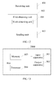
- FIG. 13 is a schematic structural diagram of an embodiment of a network device according to the present invention.
- the network device 2000 may include:
- the processor 504 performs the following steps:
- the processor 504 performing the step of parsing the message, to obtain a neighbor relationship between at least two network nodes involved in the message may include:
- the processor 504 performing the step of parsing the message, to obtain a neighbor relationship between at least two network nodes involved in the message may include:
- the processor 504 performing the step of parsing the message, to obtain a neighbor relationship between at least two network nodes involved in the message may include:
- the message further carries an identifier used for indicating that the message is an neighbor relationship reporting message.
- the processor 504 after the processor 504 performs the step of parsing the message, to obtain a neighbor relationship between at least two network nodes involved in the message, the processor further performs the following step:
- the program may be stored in a computer readable storage medium.
- the storage medium may include: a read-only memory, a random-access memory, a magnetic disk, or an optical disc.
Landscapes
- Engineering & Computer Science (AREA)
- Computer Networks & Wireless Communication (AREA)
- Signal Processing (AREA)
- Mobile Radio Communication Systems (AREA)
Applications Claiming Priority (1)
| Application Number | Priority Date | Filing Date | Title |
|---|---|---|---|
| PCT/CN2013/071494 WO2014121478A1 (zh) | 2013-02-07 | 2013-02-07 | 获取网络节点相邻关系的方法、装置和网络设备 |
Publications (3)
| Publication Number | Publication Date |
|---|---|
| EP2945421A1 true EP2945421A1 (de) | 2015-11-18 |
| EP2945421A4 EP2945421A4 (de) | 2016-03-02 |
| EP2945421B1 EP2945421B1 (de) | 2018-09-19 |
Family
ID=49800890
Family Applications (1)
| Application Number | Title | Priority Date | Filing Date |
|---|---|---|---|
| EP13874607.8A Not-in-force EP2945421B1 (de) | 2013-02-07 | 2013-02-07 | Verfahren, vorrichtung und netzwerkvorrichtung zur erfassung von nachbarschaftsbeziehungen zwischen netzwerkknoten |
Country Status (4)
| Country | Link |
|---|---|
| US (1) | US10075882B2 (de) |
| EP (1) | EP2945421B1 (de) |
| CN (1) | CN103477675B (de) |
| WO (1) | WO2014121478A1 (de) |
Families Citing this family (3)
| Publication number | Priority date | Publication date | Assignee | Title |
|---|---|---|---|---|
| CN105611632A (zh) * | 2014-11-19 | 2016-05-25 | 中兴通讯股份有限公司 | 寻呼方法、装置和系统 |
| CN116744325A (zh) * | 2022-03-04 | 2023-09-12 | 中国移动通信有限公司研究院 | 一种基站流量预测方法及相关设备 |
| CN117858114A (zh) * | 2022-09-30 | 2024-04-09 | 华为技术有限公司 | 通信方法及通信装置 |
Family Cites Families (15)
| Publication number | Priority date | Publication date | Assignee | Title |
|---|---|---|---|---|
| EP0895435B1 (de) * | 1997-07-29 | 2004-09-29 | Agilent Technologies, Inc. (a Delaware corporation) | Analyse von Nachbarzellen in zellularem Telekommunikationssystem |
| US20040151193A1 (en) * | 2002-12-23 | 2004-08-05 | Johan Rune | Bridging between a Bluetooth scatternet and an Ethernet LAN |
| ZA200608267B (en) * | 2004-03-04 | 2008-07-30 | Samsung Electronics Co Ltd | System and method for controlling an operational mode of a mac layer in a broadband wireless access communication system |
| US20090047950A1 (en) * | 2007-08-13 | 2009-02-19 | Nokia Corporation | Registration of wireless node |
| EP2316244A1 (de) * | 2008-08-07 | 2011-05-04 | Nokia Siemens Networks Oy | Optimiertes paging eines benutzergeräts |
| WO2010036167A1 (en) * | 2008-09-23 | 2010-04-01 | Telefonaktiebolaget L M Ericsson (Publ) | Method and arrangements in a cellular network with femtocells |
| JP5340397B2 (ja) * | 2008-10-20 | 2013-11-13 | テレフオンアクチーボラゲット エル エム エリクソン(パブル) | ホームノードbゲートウェイアドレスを検索するためのセルidおよびマスクの使用 |
| CN101790221B (zh) * | 2009-01-22 | 2015-05-06 | 中兴通讯股份有限公司 | 家用基站切换时网络接入控制方法及系统 |
| US8472539B2 (en) * | 2009-04-07 | 2013-06-25 | Lg Electronics Inc. | Method of transmitting power information in wireless communication system |
| CN101998679B (zh) * | 2009-08-13 | 2012-11-07 | 华为技术有限公司 | 一种传输承载的中继方法、装置和通信系统 |
| CN102045686B (zh) * | 2009-10-14 | 2015-08-12 | 株式会社Ntt都科摩 | 一种无线通信网络中支持移动性管理的方法及设备 |
| JP5478455B2 (ja) * | 2010-10-07 | 2014-04-23 | 株式会社Nttドコモ | ネットワーク装置及び移動局制御方法 |
| US8526945B2 (en) * | 2011-03-31 | 2013-09-03 | Alcatel Lucent | Tracking and paging at boundries in LTE networks |
| WO2013001054A1 (en) * | 2011-06-30 | 2013-01-03 | Nokia Siemens Networks Oy | Handover between different closed subscriber groups |
| CN102835162A (zh) * | 2012-05-29 | 2012-12-19 | 华为技术有限公司 | 寻呼终端的方法和装置及系统 |
-
2013
- 2013-02-07 EP EP13874607.8A patent/EP2945421B1/de not_active Not-in-force
- 2013-02-07 WO PCT/CN2013/071494 patent/WO2014121478A1/zh not_active Ceased
- 2013-02-07 CN CN201380000141.7A patent/CN103477675B/zh not_active Expired - Fee Related
-
2015
- 2015-08-06 US US14/820,170 patent/US10075882B2/en active Active
Also Published As
| Publication number | Publication date |
|---|---|
| EP2945421B1 (de) | 2018-09-19 |
| US10075882B2 (en) | 2018-09-11 |
| CN103477675B (zh) | 2018-02-02 |
| EP2945421A4 (de) | 2016-03-02 |
| US20150350970A1 (en) | 2015-12-03 |
| WO2014121478A1 (zh) | 2014-08-14 |
| CN103477675A (zh) | 2013-12-25 |
Similar Documents
| Publication | Publication Date | Title |
|---|---|---|
| US20200196200A1 (en) | Handover method and mobility management network element | |
| EP2645774B1 (de) | Verfahren und vorrichtungen zur freigabe kontextbezogener ressourcen von benutzervorrichtungen | |
| US9560628B2 (en) | Method and node for paging in a radio access network | |
| US20150080034A1 (en) | Method, apparatus, and system for paging terminal | |
| KR20140031970A (ko) | 기지국들 사이에서 x2 접속을 확립하는 방법, 기지국, 및 통신 시스템 | |
| CN102355751B (zh) | 自组织网络信息传输方法、系统和设备 | |
| EP3468253A1 (de) | Umschaltverfahren und -vorrichtung | |
| CN101754373B (zh) | 操作指示方法、服务网关和核心网络系统 | |
| WO2017193555A1 (zh) | 小区切换的方法和系统 | |
| JP5397535B2 (ja) | 無線通信システム、通信制御方法、移動管理装置、移動端末及び基地局 | |
| US10075882B2 (en) | Method and apparatus for obtaining neighbor relationship between network nodes and network device | |
| CN107623946A (zh) | 对轻连接状态的终端的寻呼方法和装置 | |
| JP6768116B2 (ja) | 通信制御装置選択方法および通信システム | |
| JPWO2015186277A1 (ja) | サーバ装置、基地局、情報処理方法およびプログラム | |
| CN116636257B (zh) | 利用musim的增强的服务连续性 | |
| JPWO2018034201A1 (ja) | 通信方法 | |
| EP4346277A1 (de) | Handhabung des zellwechsels von einem zielrelais-ue während indirekter pfadumschaltung eines sidelink-basierten u2n-relais | |
| US9705739B1 (en) | Systems and methods for configuring a unique access node identifier | |
| CN103338526A (zh) | 用户设备上下文相关资源的释放方法和设备 | |
| KR101817267B1 (ko) | 이기종 망에서 음성 서비스를 제공하기 위한 페이징 장치 및 방법 | |
| CN103718608A (zh) | 一种基站间的切换方法及相关装置 | |
| RU2524176C2 (ru) | Способ мобильной связи и коммутационный узел | |
| JP6551515B2 (ja) | 基地局、およびゲートウェイ | |
| CN117241257A (zh) | 终端附着请求的发送方法、装置、电子设备及存储介质 | |
| KR101487483B1 (ko) | 음성 호 연결 시간 단축을 위한 방법 및 이를 위한 교환기 |
Legal Events
| Date | Code | Title | Description |
|---|---|---|---|
| PUAI | Public reference made under article 153(3) epc to a published international application that has entered the european phase |
Free format text: ORIGINAL CODE: 0009012 |
|
| 17P | Request for examination filed |
Effective date: 20150813 |
|
| AK | Designated contracting states |
Kind code of ref document: A1 Designated state(s): AL AT BE BG CH CY CZ DE DK EE ES FI FR GB GR HR HU IE IS IT LI LT LU LV MC MK MT NL NO PL PT RO RS SE SI SK SM TR |
|
| AX | Request for extension of the european patent |
Extension state: BA ME |
|
| A4 | Supplementary search report drawn up and despatched |
Effective date: 20160128 |
|
| RIC1 | Information provided on ipc code assigned before grant |
Ipc: H04W 60/02 20090101AFI20160122BHEP Ipc: H04W 24/02 20090101ALI20160122BHEP |
|
| DAX | Request for extension of the european patent (deleted) | ||
| RAP1 | Party data changed (applicant data changed or rights of an application transferred) |
Owner name: HUAWEI TECHNOLOGIES CO., LTD. |
|
| STAA | Information on the status of an ep patent application or granted ep patent |
Free format text: STATUS: EXAMINATION IS IN PROGRESS |
|
| 17Q | First examination report despatched |
Effective date: 20170829 |
|
| REG | Reference to a national code |
Ref country code: DE Ref legal event code: R079 Ref document number: 602013044051 Country of ref document: DE Free format text: PREVIOUS MAIN CLASS: H04W0036000000 Ipc: H04W0024020000 |
|
| GRAP | Despatch of communication of intention to grant a patent |
Free format text: ORIGINAL CODE: EPIDOSNIGR1 |
|
| STAA | Information on the status of an ep patent application or granted ep patent |
Free format text: STATUS: GRANT OF PATENT IS INTENDED |
|
| RIC1 | Information provided on ipc code assigned before grant |
Ipc: H04W 68/02 20090101ALN20180314BHEP Ipc: H04W 24/02 20090101AFI20180314BHEP |
|
| RIC1 | Information provided on ipc code assigned before grant |
Ipc: H04W 24/02 20090101AFI20180320BHEP Ipc: H04W 68/02 20090101ALN20180320BHEP |
|
| INTG | Intention to grant announced |
Effective date: 20180404 |
|
| GRAS | Grant fee paid |
Free format text: ORIGINAL CODE: EPIDOSNIGR3 |
|
| GRAA | (expected) grant |
Free format text: ORIGINAL CODE: 0009210 |
|
| STAA | Information on the status of an ep patent application or granted ep patent |
Free format text: STATUS: THE PATENT HAS BEEN GRANTED |
|
| AK | Designated contracting states |
Kind code of ref document: B1 Designated state(s): AL AT BE BG CH CY CZ DE DK EE ES FI FR GB GR HR HU IE IS IT LI LT LU LV MC MK MT NL NO PL PT RO RS SE SI SK SM TR |
|
| REG | Reference to a national code |
Ref country code: GB Ref legal event code: FG4D |
|
| REG | Reference to a national code |
Ref country code: CH Ref legal event code: EP |
|
| REG | Reference to a national code |
Ref country code: AT Ref legal event code: REF Ref document number: 1044752 Country of ref document: AT Kind code of ref document: T Effective date: 20181015 |
|
| REG | Reference to a national code |
Ref country code: IE Ref legal event code: FG4D |
|
| REG | Reference to a national code |
Ref country code: DE Ref legal event code: R096 Ref document number: 602013044051 Country of ref document: DE |
|
| REG | Reference to a national code |
Ref country code: NL Ref legal event code: MP Effective date: 20180919 |
|
| PG25 | Lapsed in a contracting state [announced via postgrant information from national office to epo] |
Ref country code: NO Free format text: LAPSE BECAUSE OF FAILURE TO SUBMIT A TRANSLATION OF THE DESCRIPTION OR TO PAY THE FEE WITHIN THE PRESCRIBED TIME-LIMIT Effective date: 20181219 Ref country code: RS Free format text: LAPSE BECAUSE OF FAILURE TO SUBMIT A TRANSLATION OF THE DESCRIPTION OR TO PAY THE FEE WITHIN THE PRESCRIBED TIME-LIMIT Effective date: 20180919 Ref country code: SE Free format text: LAPSE BECAUSE OF FAILURE TO SUBMIT A TRANSLATION OF THE DESCRIPTION OR TO PAY THE FEE WITHIN THE PRESCRIBED TIME-LIMIT Effective date: 20180919 Ref country code: FI Free format text: LAPSE BECAUSE OF FAILURE TO SUBMIT A TRANSLATION OF THE DESCRIPTION OR TO PAY THE FEE WITHIN THE PRESCRIBED TIME-LIMIT Effective date: 20180919 Ref country code: GR Free format text: LAPSE BECAUSE OF FAILURE TO SUBMIT A TRANSLATION OF THE DESCRIPTION OR TO PAY THE FEE WITHIN THE PRESCRIBED TIME-LIMIT Effective date: 20181220 Ref country code: LT Free format text: LAPSE BECAUSE OF FAILURE TO SUBMIT A TRANSLATION OF THE DESCRIPTION OR TO PAY THE FEE WITHIN THE PRESCRIBED TIME-LIMIT Effective date: 20180919 Ref country code: BG Free format text: LAPSE BECAUSE OF FAILURE TO SUBMIT A TRANSLATION OF THE DESCRIPTION OR TO PAY THE FEE WITHIN THE PRESCRIBED TIME-LIMIT Effective date: 20181219 |
|
| REG | Reference to a national code |
Ref country code: LT Ref legal event code: MG4D |
|
| PG25 | Lapsed in a contracting state [announced via postgrant information from national office to epo] |
Ref country code: AL Free format text: LAPSE BECAUSE OF FAILURE TO SUBMIT A TRANSLATION OF THE DESCRIPTION OR TO PAY THE FEE WITHIN THE PRESCRIBED TIME-LIMIT Effective date: 20180919 Ref country code: LV Free format text: LAPSE BECAUSE OF FAILURE TO SUBMIT A TRANSLATION OF THE DESCRIPTION OR TO PAY THE FEE WITHIN THE PRESCRIBED TIME-LIMIT Effective date: 20180919 Ref country code: HR Free format text: LAPSE BECAUSE OF FAILURE TO SUBMIT A TRANSLATION OF THE DESCRIPTION OR TO PAY THE FEE WITHIN THE PRESCRIBED TIME-LIMIT Effective date: 20180919 |
|
| REG | Reference to a national code |
Ref country code: AT Ref legal event code: MK05 Ref document number: 1044752 Country of ref document: AT Kind code of ref document: T Effective date: 20180919 |
|
| PG25 | Lapsed in a contracting state [announced via postgrant information from national office to epo] |
Ref country code: EE Free format text: LAPSE BECAUSE OF FAILURE TO SUBMIT A TRANSLATION OF THE DESCRIPTION OR TO PAY THE FEE WITHIN THE PRESCRIBED TIME-LIMIT Effective date: 20180919 Ref country code: PL Free format text: LAPSE BECAUSE OF FAILURE TO SUBMIT A TRANSLATION OF THE DESCRIPTION OR TO PAY THE FEE WITHIN THE PRESCRIBED TIME-LIMIT Effective date: 20180919 Ref country code: AT Free format text: LAPSE BECAUSE OF FAILURE TO SUBMIT A TRANSLATION OF THE DESCRIPTION OR TO PAY THE FEE WITHIN THE PRESCRIBED TIME-LIMIT Effective date: 20180919 Ref country code: IS Free format text: LAPSE BECAUSE OF FAILURE TO SUBMIT A TRANSLATION OF THE DESCRIPTION OR TO PAY THE FEE WITHIN THE PRESCRIBED TIME-LIMIT Effective date: 20190119 Ref country code: RO Free format text: LAPSE BECAUSE OF FAILURE TO SUBMIT A TRANSLATION OF THE DESCRIPTION OR TO PAY THE FEE WITHIN THE PRESCRIBED TIME-LIMIT Effective date: 20180919 Ref country code: CZ Free format text: LAPSE BECAUSE OF FAILURE TO SUBMIT A TRANSLATION OF THE DESCRIPTION OR TO PAY THE FEE WITHIN THE PRESCRIBED TIME-LIMIT Effective date: 20180919 Ref country code: ES Free format text: LAPSE BECAUSE OF FAILURE TO SUBMIT A TRANSLATION OF THE DESCRIPTION OR TO PAY THE FEE WITHIN THE PRESCRIBED TIME-LIMIT Effective date: 20180919 Ref country code: NL Free format text: LAPSE BECAUSE OF FAILURE TO SUBMIT A TRANSLATION OF THE DESCRIPTION OR TO PAY THE FEE WITHIN THE PRESCRIBED TIME-LIMIT Effective date: 20180919 Ref country code: IT Free format text: LAPSE BECAUSE OF FAILURE TO SUBMIT A TRANSLATION OF THE DESCRIPTION OR TO PAY THE FEE WITHIN THE PRESCRIBED TIME-LIMIT Effective date: 20180919 |
|
| PG25 | Lapsed in a contracting state [announced via postgrant information from national office to epo] |
Ref country code: SK Free format text: LAPSE BECAUSE OF FAILURE TO SUBMIT A TRANSLATION OF THE DESCRIPTION OR TO PAY THE FEE WITHIN THE PRESCRIBED TIME-LIMIT Effective date: 20180919 Ref country code: SM Free format text: LAPSE BECAUSE OF FAILURE TO SUBMIT A TRANSLATION OF THE DESCRIPTION OR TO PAY THE FEE WITHIN THE PRESCRIBED TIME-LIMIT Effective date: 20180919 Ref country code: PT Free format text: LAPSE BECAUSE OF FAILURE TO SUBMIT A TRANSLATION OF THE DESCRIPTION OR TO PAY THE FEE WITHIN THE PRESCRIBED TIME-LIMIT Effective date: 20190119 |
|
| REG | Reference to a national code |
Ref country code: DE Ref legal event code: R097 Ref document number: 602013044051 Country of ref document: DE |
|
| PLBE | No opposition filed within time limit |
Free format text: ORIGINAL CODE: 0009261 |
|
| STAA | Information on the status of an ep patent application or granted ep patent |
Free format text: STATUS: NO OPPOSITION FILED WITHIN TIME LIMIT |
|
| PG25 | Lapsed in a contracting state [announced via postgrant information from national office to epo] |
Ref country code: DK Free format text: LAPSE BECAUSE OF FAILURE TO SUBMIT A TRANSLATION OF THE DESCRIPTION OR TO PAY THE FEE WITHIN THE PRESCRIBED TIME-LIMIT Effective date: 20180919 |
|
| 26N | No opposition filed |
Effective date: 20190620 |
|
| REG | Reference to a national code |
Ref country code: CH Ref legal event code: PL |
|
| PG25 | Lapsed in a contracting state [announced via postgrant information from national office to epo] |
Ref country code: MC Free format text: LAPSE BECAUSE OF FAILURE TO SUBMIT A TRANSLATION OF THE DESCRIPTION OR TO PAY THE FEE WITHIN THE PRESCRIBED TIME-LIMIT Effective date: 20180919 Ref country code: LU Free format text: LAPSE BECAUSE OF NON-PAYMENT OF DUE FEES Effective date: 20190207 Ref country code: SI Free format text: LAPSE BECAUSE OF FAILURE TO SUBMIT A TRANSLATION OF THE DESCRIPTION OR TO PAY THE FEE WITHIN THE PRESCRIBED TIME-LIMIT Effective date: 20180919 |
|
| REG | Reference to a national code |
Ref country code: BE Ref legal event code: MM Effective date: 20190228 |
|
| REG | Reference to a national code |
Ref country code: IE Ref legal event code: MM4A |
|
| PG25 | Lapsed in a contracting state [announced via postgrant information from national office to epo] |
Ref country code: LI Free format text: LAPSE BECAUSE OF NON-PAYMENT OF DUE FEES Effective date: 20190228 Ref country code: CH Free format text: LAPSE BECAUSE OF NON-PAYMENT OF DUE FEES Effective date: 20190228 |
|
| PG25 | Lapsed in a contracting state [announced via postgrant information from national office to epo] |
Ref country code: IE Free format text: LAPSE BECAUSE OF NON-PAYMENT OF DUE FEES Effective date: 20190207 |
|
| PG25 | Lapsed in a contracting state [announced via postgrant information from national office to epo] |
Ref country code: BE Free format text: LAPSE BECAUSE OF NON-PAYMENT OF DUE FEES Effective date: 20190228 |
|
| PG25 | Lapsed in a contracting state [announced via postgrant information from national office to epo] |
Ref country code: TR Free format text: LAPSE BECAUSE OF FAILURE TO SUBMIT A TRANSLATION OF THE DESCRIPTION OR TO PAY THE FEE WITHIN THE PRESCRIBED TIME-LIMIT Effective date: 20180919 |
|
| PG25 | Lapsed in a contracting state [announced via postgrant information from national office to epo] |
Ref country code: MT Free format text: LAPSE BECAUSE OF NON-PAYMENT OF DUE FEES Effective date: 20190207 |
|
| PG25 | Lapsed in a contracting state [announced via postgrant information from national office to epo] |
Ref country code: CY Free format text: LAPSE BECAUSE OF FAILURE TO SUBMIT A TRANSLATION OF THE DESCRIPTION OR TO PAY THE FEE WITHIN THE PRESCRIBED TIME-LIMIT Effective date: 20180919 |
|
| PG25 | Lapsed in a contracting state [announced via postgrant information from national office to epo] |
Ref country code: HU Free format text: LAPSE BECAUSE OF FAILURE TO SUBMIT A TRANSLATION OF THE DESCRIPTION OR TO PAY THE FEE WITHIN THE PRESCRIBED TIME-LIMIT; INVALID AB INITIO Effective date: 20130207 |
|
| PG25 | Lapsed in a contracting state [announced via postgrant information from national office to epo] |
Ref country code: MK Free format text: LAPSE BECAUSE OF FAILURE TO SUBMIT A TRANSLATION OF THE DESCRIPTION OR TO PAY THE FEE WITHIN THE PRESCRIBED TIME-LIMIT Effective date: 20180919 |
|
| PGFP | Annual fee paid to national office [announced via postgrant information from national office to epo] |
Ref country code: GB Payment date: 20221230 Year of fee payment: 11 |
|
| PGFP | Annual fee paid to national office [announced via postgrant information from national office to epo] |
Ref country code: FR Payment date: 20230110 Year of fee payment: 11 |
|
| PGFP | Annual fee paid to national office [announced via postgrant information from national office to epo] |
Ref country code: DE Payment date: 20221230 Year of fee payment: 11 |
|
| REG | Reference to a national code |
Ref country code: DE Ref legal event code: R119 Ref document number: 602013044051 Country of ref document: DE |
|
| GBPC | Gb: european patent ceased through non-payment of renewal fee |
Effective date: 20240207 |
|
| PG25 | Lapsed in a contracting state [announced via postgrant information from national office to epo] |
Ref country code: DE Free format text: LAPSE BECAUSE OF NON-PAYMENT OF DUE FEES Effective date: 20240903 |
|
| PG25 | Lapsed in a contracting state [announced via postgrant information from national office to epo] |
Ref country code: GB Free format text: LAPSE BECAUSE OF NON-PAYMENT OF DUE FEES Effective date: 20240207 |
|
| PG25 | Lapsed in a contracting state [announced via postgrant information from national office to epo] |
Ref country code: FR Free format text: LAPSE BECAUSE OF NON-PAYMENT OF DUE FEES Effective date: 20240229 |
|
| PG25 | Lapsed in a contracting state [announced via postgrant information from national office to epo] |
Ref country code: GB Free format text: LAPSE BECAUSE OF NON-PAYMENT OF DUE FEES Effective date: 20240207 Ref country code: FR Free format text: LAPSE BECAUSE OF NON-PAYMENT OF DUE FEES Effective date: 20240229 Ref country code: DE Free format text: LAPSE BECAUSE OF NON-PAYMENT OF DUE FEES Effective date: 20240903 |