EP2945885B1 - Capsule pour boissons - Google Patents
Capsule pour boissons Download PDFInfo
- Publication number
- EP2945885B1 EP2945885B1 EP13828869.1A EP13828869A EP2945885B1 EP 2945885 B1 EP2945885 B1 EP 2945885B1 EP 13828869 A EP13828869 A EP 13828869A EP 2945885 B1 EP2945885 B1 EP 2945885B1
- Authority
- EP
- European Patent Office
- Prior art keywords
- opening
- nozzle
- capsule according
- capsule
- fluid
- Prior art date
- Legal status (The legal status is an assumption and is not a legal conclusion. Google has not performed a legal analysis and makes no representation as to the accuracy of the status listed.)
- Not-in-force
Links
Images



Classifications
-
- B—PERFORMING OPERATIONS; TRANSPORTING
- B65—CONVEYING; PACKING; STORING; HANDLING THIN OR FILAMENTARY MATERIAL
- B65D—CONTAINERS FOR STORAGE OR TRANSPORT OF ARTICLES OR MATERIALS, e.g. BAGS, BARRELS, BOTTLES, BOXES, CANS, CARTONS, CRATES, DRUMS, JARS, TANKS, HOPPERS, FORWARDING CONTAINERS; ACCESSORIES, CLOSURES, OR FITTINGS THEREFOR; PACKAGING ELEMENTS; PACKAGES
- B65D85/00—Containers, packaging elements or packages, specially adapted for particular articles or materials
- B65D85/70—Containers, packaging elements or packages, specially adapted for particular articles or materials for materials not otherwise provided for
- B65D85/804—Disposable containers or packages with contents which are mixed, infused or dissolved in situ, i.e. without having been previously removed from the package
- B65D85/8043—Packages adapted to allow liquid to pass through the contents
- B65D85/8055—Means for influencing the liquid flow inside the package
-
- B—PERFORMING OPERATIONS; TRANSPORTING
- B01—PHYSICAL OR CHEMICAL PROCESSES OR APPARATUS IN GENERAL
- B01F—MIXING, e.g. DISSOLVING, EMULSIFYING OR DISPERSING
- B01F21/00—Dissolving
- B01F21/10—Dissolving using driven stirrers
-
- B—PERFORMING OPERATIONS; TRANSPORTING
- B01—PHYSICAL OR CHEMICAL PROCESSES OR APPARATUS IN GENERAL
- B01F—MIXING, e.g. DISSOLVING, EMULSIFYING OR DISPERSING
- B01F27/00—Mixers with rotary stirring devices in fixed receptacles; Kneaders
- B01F27/05—Stirrers
- B01F27/11—Stirrers characterised by the configuration of the stirrers
- B01F27/112—Stirrers characterised by the configuration of the stirrers with arms, paddles, vanes or blades
- B01F27/1125—Stirrers characterised by the configuration of the stirrers with arms, paddles, vanes or blades with vanes or blades extending parallel or oblique to the stirrer axis
-
- B—PERFORMING OPERATIONS; TRANSPORTING
- B01—PHYSICAL OR CHEMICAL PROCESSES OR APPARATUS IN GENERAL
- B01F—MIXING, e.g. DISSOLVING, EMULSIFYING OR DISPERSING
- B01F27/00—Mixers with rotary stirring devices in fixed receptacles; Kneaders
- B01F27/55—Mixers with rotary stirring devices in fixed receptacles; Kneaders with stirrers driven by the moving material
-
- B—PERFORMING OPERATIONS; TRANSPORTING
- B01—PHYSICAL OR CHEMICAL PROCESSES OR APPARATUS IN GENERAL
- B01F—MIXING, e.g. DISSOLVING, EMULSIFYING OR DISPERSING
- B01F35/00—Accessories for mixers; Auxiliary operations or auxiliary devices; Parts or details of general application
- B01F35/50—Mixing receptacles
- B01F35/51—Mixing receptacles characterised by their material
-
- B—PERFORMING OPERATIONS; TRANSPORTING
- B01—PHYSICAL OR CHEMICAL PROCESSES OR APPARATUS IN GENERAL
- B01F—MIXING, e.g. DISSOLVING, EMULSIFYING OR DISPERSING
- B01F35/00—Accessories for mixers; Auxiliary operations or auxiliary devices; Parts or details of general application
- B01F35/71—Feed mechanisms
- B01F35/717—Feed mechanisms characterised by the means for feeding the components to the mixer
- B01F35/7179—Feed mechanisms characterised by the means for feeding the components to the mixer using sprayers, nozzles or jets
-
- B—PERFORMING OPERATIONS; TRANSPORTING
- B01—PHYSICAL OR CHEMICAL PROCESSES OR APPARATUS IN GENERAL
- B01F—MIXING, e.g. DISSOLVING, EMULSIFYING OR DISPERSING
- B01F2101/00—Mixing characterised by the nature of the mixed materials or by the application field
- B01F2101/06—Mixing of food ingredients
- B01F2101/14—Mixing of ingredients for non-alcoholic beverages; Dissolving sugar in water
Definitions
- the invention relates to capsules or containers for preparing beverages in automatic brewing machines, and in particular it relates to a sealed single-dose and disposable capsule containing a soluble, or freeze-dried, or dehydrated initial product capable of making a final product, for example, a beverage, by interacting with a pressurized fluid, typically water or milk.
- a pressurized fluid typically water or milk.
- the known capsules for use in known brewing machines are disposable and single-dose containers comprising an external casing, made of liquid- and gas-impermeable plastics and having the shape of a glass or a cup.
- the casing has a bottom wall and a side wall defining a cavity provided with an upper opening through which the product can be inserted from which the beverage can be obtained.
- the upper opening is hermetically sealed by a cover, typically an aluminium or plastic film sheet, so as to seal the product inside the container cavity.
- the capsule is perforable to allow the inflow of pressurized liquid, typically water, and the exit of the obtained beverage.
- the cover and the bottom wall of the casing are perforable by suitable means of the brewing machine, to allow the dispensing from the top of the pressurized liquid and the extraction from the bottom of the beverage, respectively.
- a drawback of the known capsules disclosed above is that they can be used only in brewing machines provided with a special dispensing circuit comprising extracting means suitable to perforate the capsule bottom to allow the outflow of the beverage, and duct means suitable to convey the beverage to the fruition container (for example, a mug, a cup, a glass, etc.).
- a dispensing circuit makes the machine structure more complex and expensive.
- dispensing circuit since such dispensing circuit is in contact with the dispensed beverages, it should be suitably washed after each dispensing operation, both for hygienic reasons, and not to compromise the taste and quality (organoleptic qualities) of a beverage that is subsequently dispensed (for example, an aromatic infusion dispensed after a coffee).
- washing means of the dispensing circuit is not always present in the known machines, due to their manufacturing complexity and costs.
- the known brewing machines further comprise a supply circuit provided with injection means (typically, needles or sharpened nozzles) providing to perforate the cover and dispense the pressurized liquid coming from a pump and/or a boiler.
- injection means typically, needles or sharpened nozzles
- the injection means can contact the product and/or the beverage, thus getting contaminated.
- the insertion means of the supply circuit should be suitably washed after each dispensing operation, due to hygienic reasons, and to not compromise the organoleptic properties of a beverage dispensed at a later moment.
- WO2012/104760 US2011/110180 , US2011/045144 and DE102010030988 are documents defining the general state of the art on the technical field of disposable containers and capsules for beverages.
- the known capsules disclosed above allow to obtain a final product by percolation of the liquid through the initial product (typically, coffee) or by solubilization or dissolution of the initial product (for example, tea, infusions, etc.).
- the initial product has to be easily and quickly soluble, so as to avoid the formation of clots or lumps inside the capsule and/or in the fruition container.
- An object of the present invention is to improve the known capsules for beverages or fluid food products, in particular sealed, disposable and single-dose capsules containing a soluble or freeze-dried or dehydrated product suitable to interact with a fluid, typically hot pressurized water, to prepare a corresponding final product in an automatic brewing machine.
- Still another object is to obtain a capsule allowing obtaining in a brewing machine, automatically and without the manual intervention of a user, dense and meaty (for example, chocolate) or viscous final products perfectly dissolved and free from clots and lumps, obtained starting from initial products not much or slowly soluble and/or containing thickeners and/or stabilizers.
- dense and meaty for example, chocolate
- viscous final products perfectly dissolved and free from clots and lumps, obtained starting from initial products not much or slowly soluble and/or containing thickeners and/or stabilizers.
- a further object is to manufacture a hermetic and sealed capsule, of the perforable type, and capable of dispensing a final product directly into a fruition container (cup, glass, etc.).
- Still another object is to obtain a capsule allowing not to contaminate or pollute with the initial product and/or with the final product means or parts of the brewing machine, thereby ensuring both the hygiene and the cleanliness of the latter, and the taste and quality, i.e., the integrity of the organoleptic properties, of the final product.
- a still different object is to obtain an extremely versatile capsule, capable of meeting the tastes of multiple different consumers, while keeping the initial product contained therein unaltered.
- a further different object is to obtain a capsule capable of dispensing a final product into a fruition container (cup, glass, etc.) allowing a user separating in a simple manner components in recyclable plastics of which the capsule is made, from non-recyclable components such as, for example, multilayered polylaminates containing aluminum.
- a capsule 1 according to the invention is illustrated, containing an initial product P and usable in an automatic brewing machine to produce, by injection of a pressurized fluid therein, a final product B, for example, a beverage, such as coffee, barley, tea, etc.
- a final product B for example, a beverage, such as coffee, barley, tea, etc.
- the initial product P is, for example, a soluble or freeze-dried or dehydrated food product.
- the capsule 1 comprises an external casing 2, or container, substantially in the shape of a glass or a cup, provided with a base wall 3 and with a side wall 4, defining a cavity 5 which is open and suitable to contain the initial product P from which the final product B can be obtained.
- the casing 2 is compressible and/or crushable and/or deformable, obtained by forming of a thermoformable material sheet, in particular a liquid- and gas-impermeable multilayered plastics and suitable for contact with foodstuffs.
- the side wall 4 is deformable and/or compressible along preset pliability lines 17, for example, having a helicoidal trend, or it is made in the shape of an accordion or of a bellows, as in the embodiment illustrated in Figure 16 .
- the side wall 4 is divergent starting from the base wall 3 to a peripheral flange-shaped edge 6, for example, having an almost frusto-conical shape.
- the base wall 3 is, for example, concave in the direction of the cavity 5.
- the capsule 1 comprises a nozzle 7 associated with the casing 2 arranged to introduce a fluid F into the cavity 5, in particular a pressurized hot liquid, for example water or milk, capable of interacting with the initial product P to obtain the final product B.
- a fluid F into the cavity 5
- a pressurized hot liquid for example water or milk
- the nozzle is provided with at least one outflow opening 11 arranged to introduce a fluid flow F into the cavity 5 in a preparation step of the final product B.
- the capsule 1 also comprises a mixing element 20 rotatably coupled to the nozzle 7 at the outflow opening 11 and so shaped as to divert the exiting fluid and be rotated by the latter about the nozzle 7, so as to create inside said cavity 5 a vortex flow of fluid F and initial P and final B product.
- the nozzle 7 and the mixing element 20 are made of plastics, in particular by injection molding.
- the mixing element 20 comprises a central portion 21, or hub, rotatably connectable to a connecting portion of the nozzle 7, in an assembled configuration W, and at least one blade 22 fixed to the central portion 21 and extending from the latter substantially radially outwardly.
- the central portion 21 has an annular shape, and it is rotatably and co-axially mounted on the nozzle 7.
- the mixing element 20 comprises a pair of opposite blades 22, i.e. spaced apart by 180° with respect to a rotation axis Y of the mixer 20, said rotation axis substantially coinciding with a longitudinal axis X of the nozzle 7.
- the mixing element 20 that may rotate freely and idle about the rotation axis Y forms a kind of propeller or rotor capable of moving and mixing the fluid F and the initial product P.
- Each blade 22 has an elongated shape and extends from the hub 21 radially outwardly.
- each blade 22 has an arched shape and comprises a shaped portion 22a having a concave shape intended to intercept the jet L exiting the nozzle 7.
- the hub 21 comprises a through hollow 24 arranged to house, contain, and engage with the connecting portion of the nozzle 7.
- the hub 21 further comprises at least one supplying opening 23 obtained transversally on a tubular wall thereof, connected to the outflow opening 11 in the assembled configuration W and arranged to convey a respective jet L of fluid F, or a portion thereof, exiting the latter towards the shaped portion 22a of the respective blade 22.
- the hub comprises a supplying opening 23 for each blade 22.
- the shaped portion 22a intercepts the jet L of fluid F coming from the supplying opening 23.
- the supplying openings 23 in the assembled configuration W face a supplying groove 12 of the nozzle 7 which is flowingly connected with the outflow opening 11.
- the supplying groove 12 receives the flow of fluid F from the latter and acts as a supply manifold of the above-mentioned fluid F for the supplying openings 23 of the mixing element 20.
- the fluid flow exiting the outflow opening 11 is then divided into two jets L exiting uniformly and continuously the supplying openings 23 during the rotation of the mixing element 20.
- the jets L exert a thrust on the blades 22 such as to rotate the mixing element 22.
- Locking means 15, 25 is provided to elastically and reversibly restrain the mixing element 20 to the nozzle 7 in the assembled configuration W, in any case allowing the free rotation thereof about the rotation axis Y.
- the locking means comprises one or more stop teeth 25, for example six in number, obtained on the hub 21 and arranged to elastically engage in a stop groove 15 obtained on the nozzle 7 and adjacent to the supplying groove 12.
- the stop teeth 25 obtained on an edge of the hub 21 are arranged mutually angularly spaced apart.
- Each stop tooth 25 comprises an abutting end 25a, intended to insert in the stop groove 15 and provided with a pair of planes that are tilted with respect to the rotation axis Y.
- Such tilted planes allow, by virtue of the elasticity of the plastics of the nozzle 7 and of the mixing element 20, rotatably coupling the mixing element 20 to the nozzle 7 in an assembling step of the capsule 1 and uncoupling the mixing element 20 and allowing it to slide along the nozzle 7, in a dispensing step of the final product B, as best explained in following of the description.
- the dimensions, shape, inclination, number and arrangement of the blades 22 of the mixing element 20 may be suitably selected as a function of the type and composition of the initial product P.
- the nozzle 7 comprises an elongated and rigid tubular element, having a longitudinal side wall 10, a first end 8, and a second end 9 mutually opposite.
- the first end 8 is provided with a first opening 13 arranged to engage with injection means of a brewing machine capable of dispensing the fluid F
- the longitudinal side wall 10 is provided with the outflow opening 11 that is flowingly connected, via a first duct 14, to the first opening 13 and it is arranged to introduce the fluid F into the cavity 5 in an injecting step J, as best disclosed in the following description.
- the second end 9 is provided with a second opening 16 flowingly connected via a second duct 17 with a dispensing opening 18 obtained on the longitudinal side wall 10 of the nozzle 7.
- the dispensing opening 18, the second duct 17, and the second opening 16 allow the final product B exiting the cavity 5 and being dispensed directly into a fruition container when the casing 2 is compressed and/or crushed.
- the first duct 14 and the second duct 17 are placed side by side, in particular, they are parallel to one another and to a longitudinal axis X of the nozzle 7, and extend substantially over the entire length of the nozzle 7.
- the outflow opening 11 is obtained in the proximity of the second end 9, while the dispensing opening 18 is obtained in the proximity of the first end 8.
- the nozzle 7 is arranged inside the cavity 5 with the second end 9 partially exiting the above-mentioned cavity 5 through an exit opening 31 obtained in the base wall 3.
- the nozzle 7 inserts and may slide with interference (thus making a hydraulic sealing) in the exit opening 31; in such a manner, as best explained in the following description, the final product B may exit the capsule 1 only through the nozzle 7, and in particular through the dispensing opening 18, the second duct 17, and the second opening 16.
- the second end 9 of the nozzle 7 has a peripheral edge or also external flange 9a opposite the first end 8, which in particular peripherally surrounds the second opening 16.
- the external flange 9a abuts against an external surface of the base wall 3.
- a closing element 39 ( Figures 16 and 17 ) is provided to hermetically close the second opening 16 of the nozzle 7 and insulating from the external environment the cavity 5.
- the closing element 39 for example in the shape of a disc, comprises a joining, for example annular, edge, 39a by which it is removably fixed to an external surface of the base wall 3.
- the closing element 39 may be easily detached from the base wall 3 in an automatic manner by the nozzle 7 in an initial partial crushing step of the casing 2, or again by the pressure of the air contained inside the cavity 5, which is in turn pushed to the outside by the introduction of the fluid F into the capsule during the injecting step J.
- the closing element 39 may be further easily detached from the base wall 3 manually by a user before the insertion of the capsule 1 into the brewing machine, and in this case it is provided, according to a preferred embodiment, with an elongated tab 39b extending outwardly starting from a connecting portion of the joining edge 39a.
- the closing element 39 is made of plastics, or aluminum, weldable, for example thermally or by ultrasounds, and the joining edge 39a is, in particular, fixed to the external surface of the base wall 3 by a first portion 239a by a blocking seal and by a second portion 239b by a peelable seal, the blocking seal requiring a greater force compared to the peelable seal to release the joining edge 39a from the base wall 3, so as to promote the release of the second portion 239b of the joining edge 39a before releasing the first portion 239a.
- the first portion 239a extends in a first angular interval comprised between 80° and 100°, in particular preferably 100°, and the second portion 239b extends in a second angular interval that is explementary to the first angular interval, in other words, the first portion 239a and the second portion 239b extend over the entire joining edge 39a.
- the closing element 39 is provided with the elongated tab 39b, the connecting portion of the joining edge 39a extends from the first portion 239a fixed by the blocking seal, due to reasons that will be best seen herein below.
- the second portion 239b fixed by a peelable seal, comprises detachment promoting means to promote a gradual and progressive separation of the joining edge 39a from the base wall 3, which comprise at least one detachment portion 240, at which the second portion 239b has substantially a "V", or wedge, shape.
- the detachment promoting means comprises a plurality of detachment portions 240 angularly equidistant in the second portion 239b, as shown in Figure 12 , to distribute the efficiency of such release along the entire second portion 239b.
- the first portion 239a fixed by the blocking seal is devoid of the detachment promoting means, and, therefore, although both the blocking seal and the peelable seal allow removably fixing the closing element 39 to the base wall 3, the blocking seal requires a greater force compared to the peelable seal to allow the release of the first portion 239a with respect to the second portion 239b.
- the tab 39b is present, and only one detachment portion 240 (not illustrated) is present, the latter is located in the second portion 239b along a symmetry axis S of the tab 39b, on the opposite side with respect to the tab 39b.
- the first portion 239a remains connected to the base wall 3 and acts as a hinge element about which the portion of the closing element 39 comprising the second portion 239a of the joining edge 39a may rotate, away from the base wall 3.
- the closing element 39 may be removably fixed to the external flange 9a so as to hermetically close the second opening 16.
- the closing element has to be manually detached by the user before inserting the capsule 1 into the brewing machine.
- the capsule 1 further comprises a covering element 19 that may be fixed to the edge 6 of the casing 2 to hermetically close the cavity 5.
- the covering element 19 is perforable, in particular by the injection means of a brewing machine, to introduce the fluid F into the nozzle 7.
- the covering element 19 is fixed by means of a welding also to the first end 8 of the nozzle 7, collaborating with the exit opening 31 to keep the above-mentioned nozzle 7 in place inside the cavity 5, and above all creating a fluid seal between the covering element 19 and the above-mentioned first end 108. In this manner, the fluid F received from the nozzle 7 in the first opening 13 is dispensed to the containing cavity of the product P only through the outflow opening 11 and undesired leaks of the fluid F at the first end 8 are avoided.
- Both the closing element 39 and the covering element 19 are made of selected materials, for example, multilayered plastic polylaminates, so as to protect over time from moisture and oxygen the initial product P contained in the capsule.
- multilayered plastics may for example contain aluminum or a different barrier layer, for example, ethylene vinyl alcohol (EVOH) or polyvinylidene chloride (PVDC). If they contain, for example, aluminum, they cannot be considered as recyclable plastics, therefore they have to be divided from the remaining plastics composing the capsule to the aims of waste disposal.
- the operation or use of the capsule 1 of the invention in an automatic brewing machine provides for an initial step of partial crushing of the casing 2 to allow the nozzle 7, slidable with interference in the exit opening 31, further exiting the latter, at least partially detaching the closing element 39.
- the portion of the closing element 39 comprising the second portion 239b rotates away from the base wall 3 about the first portion 239a, still connected to the base wall, acting as a hinge line of the closing element 39.
- the nozzle 7 is supplied by injection means of the brewing machine capable of perforating the covering element 19 and engaging the first opening 13.
- the closing element 39 may be manually removed by the user before inserting the capsule 1 into the brewing machine.
- the casing 2 needs not to be partially compressed and crushed before and/or during the injecting step J of the fluid F.
- the fluid F introduced by the nozzle 7, and in particular through the outflow opening 11 of the nozzle 7 and through the supplying openings 23 of the mixing element 20, may interact with the initial product P to gradually form the final product B.
- the casing 2 of the capsule 1 is partially crushed (to allow the nozzle detaching the closing element 39) and the second end 9 of the nozzle 7 is engaged, seal fit in the exit opening 31. Since the dispensing opening 18 is in the proximity of the first end 8 of the nozzle 7, the fluid F, the mixture of fluid and initial product P, and the final product B progressively forming on the bottom of the capsule 1, cannot exit externally to the latter through the second opening 16.
- the jets L of fluid exiting the supplying openings 23 hit the blades 22 of the mixing element 20 rotating the latter about the rotation axis Y. Meanwhile, the jets L are diverted, by virtue of the shape of the blades 22 and the shaped portions 22a of the latter ones, in a direction substantially tangential with respect to the rotation axis Y with an opposite direction to the of rotation direction R of the mixing element 20.
- the mixing element 20 and the jets L create in the cavity 5 a vortex flow of fluid F and initial product P, progressively mixed, which from the base wall 3 goes upwards, i.e., towards the edge 6 of the casing 2.
- the initial product P is moved and mixed with the fluid F gradually and progressively with the introduction of the latter inside the cavity 5.
- the mixing procedure that is obtained with the capsule 1 of the invention is similar to the optimum manual procedure providing for gradually adding the fluid to the initial product and mixing continuously the mixture adding fluid until obtaining the final product.
- the pressure and temperature of the fluid F introduced into the cavity 5 have to be suitably adjusted as a function of the type and composition of the initial product P.
- the cavity 5 of the capsule 1 is filled with the amount or volume of fluid F necessary before the dispensing step.
- the dispensing step may be implemented by progressively compressing and crushing the casing 2 along the direction A so as to allow the nozzle 7 to further exit the cavity 5 through the exit opening 31, and moreover so as to force the final product B to exit the cavity 5 through the dispensing opening 18, the second duct 17, and the second opening 16. Since the longitudinal side wall 10 of the nozzle 7 abuts against and sealingly slides in the exit opening 31, and since the cavity 5 is closed, crushing and compressing the casing 2 the final product B contained therein is in fact forced by the pressure to enter the dispensing opening 18 and exit the capsule 1 through the second duct 17 and the second opening 16, directly in the fruition container.
- the locking means 15, 25 allow the mixing element 20, pushed by the base wall 3, uncoupling from the nozzle 7 and sliding along the latter towards the first end 8 so as to allow the compression and crushing of the casing 2.
- the nozzle 7 allows dispensing at the same time the fluid F (through the first duct 14 and the outflow opening 11) and the final product B (through the second duct 17 and the second opening 16) so as to further dilute the latter and to obtain a desired dose of final product.
- Such operation which with the known capsules has to be implemented manually by the user, may be instead carried out in an automatic manner by the brewing machine using the capsule 1 of the invention.
- the capsule 1 of the invention allows dispensing into the container only the final product B (during the dispensing step E) at the end of the solubilization and/or dissolution thereof.
- the configuration of the nozzle 7 prevents the exit also accidental of the fluid F from the capsule 1 during the preparation step of the final product B.
- the dispensing step E may be initially carried out by continuing injecting the fluid F into the cavity 5, thus forcing the final product B to exit due to the action of the pressure from the capsule 1. Subsequently, by completely compressing and crushing the casing 2, the complete outflow of the final product B from the capsule is obtained. It shall be noticed that also with such dispensing manner, it is possible to dilute the final product B and obtain a desired final amount thereof that is greater than the capsule capacity. Such operation, which with the known capsules has to be carried out manually by the user, may be instead carried out in an automatic manner by the brewing machine using the capsule 1 of the invention.
- a user may manually complete the removal of the covering element 19 (and to such aim, in a non-illustrated embodiment, the covering element could also be provided with an elongated tab) and/or of the closing element 39, in order to separate components in recyclable plastics, as surely the casing 2 and the nozzle 7 are, from non-recyclable components, as could be the covering element 19 and/or the closing element 139, if they are made in a multilayered plastics containing for example aluminium.
- the user may separate it from the capsule 1 by grasping the portion already detached of the closing element 39 comprising the second portion 239b or the user may advantageously, if present, grasp the tab 39b connected to the first portion 239a of the joining edge 39a thus avoiding getting contaminated and/or wetted in case the above-mentioned already detached portion contacted during the dispensing operation the final product B.
- Figure 18 illustrates a further version of the capsule 1 differing from the capsule in Figure 1 in that it comprises a solid product UP, schematically illustrated, contained in the second duct 17 and dispensable directly into a fruition container through the second opening 16 before the dispensing step E.
- the solid product UP may be soluble or not soluble, and it is intended to be consumed together with the final product B.
- the solid product UP may be composed of only one element (for example, a cookie, or a crouton or a piece of bread), or by a plurality of elements, such element(s) having at least one dimension (length, width, or height) that is greater than, or the same as, a width of the dispensing opening 18, so that the dispensing opening 18 prevents such solid product UP exiting the second duct 17 towards the cavity 5.
- the solid product UP remains inside the second duct 17 separated from the initial product P all the time that the capsule 1 remains unused.
- the solid product UP may comprise multiple elements that are homogenous to each other, i.e., of the same type, such as, for example sweeteners, or cereals, colored or not, or croutons, and the like, or a plurality of elements that are mutually non-homogenous, for example, a mixture of sweeteners and cereals.
- the solid product UP may be inserted into the capsule 1 at the production line, this reducing and simplifying a product storehouse. This further allows diversifying, in a packaging step, capsules 1 containing a same initial product P. In fact, in the packaging step it is possible to add to the capsules 1 containing a same initial product P, a plurality of different solid products UP. For example, it is possible to add to the capsule 1 containing a same product P, a solid product UP composed of a sweetener, or a solid product UP composed of cereals.
- capsule 1 in an automatic brewing machine is substantially similar to that of the capsule in Figure 1 as regards the preparation of the final product B.
- the capsule in Figure 1b allows using the solid product UP.
- the solid product UP may be dispensed directly into the fruition container in an automatic manner. According to such manner, the step of partial crushing of the casing 2 allows the nozzle 7 at least partially detaching the closing element 39, so as to connect the second duct 17 to the external environment via the second opening 16, and allow the exit of the solid product UP from the second duct 17 towards the fruition container.
- the solid product UP may be dispensed directly into the fruition container in a manual manner.
- the closing element 39 is manually detached from the base wall 3 by a user before inserting the capsule 1 into the brewing machine.
- the user at discretion, may determine the amount of solid product UP to be dispensed into the fruition container, for example, in the case that the solid product UP is a sweetener, to obtain a sweeter or less sweet final product B.
- the user may also decide not to use the solid product UP at all. In this case, the user has only to remove the solid product UP from the second duct 17 without inserting it into the fruition container.
- Figure 19 illustrates a further version of the capsule 1 differing from the capsule in Figure 1 in that it comprises interaction means for interacting with the final product B contained in the second duct 17, to further vary organoleptic or visual characteristics of such final product B before the dispensing into the fruition container.
- Such interaction means comprise a vortex flow generating member and/or a perforated member (not illustrated), the latter to perform a filtering function or, alternatively, to reduce or eliminate possible froth present in the final product B.
- the vortex flow generating member comprises an elongated and rigid tubular-shaped insert 528 having a longitudinal side wall 529 provided with a helicoidal projection 530 extending longitudinally at least along a portion of said insert 528, preferably along the entire insert 528.
- the insert 528 is contained in the second duct 17 and creates an annular gap 531, between a smooth wall 532 of the second duct 17 and said side wall 529 provided with the projection 530.
- the annular gap 531 has channels with a helicoidal trend, to generate the vortex flow of fluid into the annular gap. In this manner, the final product B, before being dispensed into the fruition container, is rotated and forced to flow with a vortex motion into the annular gap 531.
- the final product B is further mixed, thus the complete and homogeneous solubilization of products not much or slowly soluble is further promoted.
- the vortex motion may, in addition or alternatively, promote the formation of froth in the final product B, if desired.
- the insert 528 further comprises end projections 533 allowing holding the same insert 528 in place inside the second duct 17 by interference. Between a projection 533 and the other one, dispensing passages of the final product B are defined.
- the projection 530 illustrated in Figure 1b has a longitudinal extent such as to be in the shape of a band, with coils tilted by 30° with respect to a longitudinal axis of the insert 528.
- the projection 530 may be also made in the shape of a thread (not shown).
- the pitch of the coils, the longitudinal extent of each coil, which dictates whether the projection is in the form of a band or a thread, and the thickness of the projection 530 in the perpendicular direction to the longitudinal axis of the insert 528 determine the rotation in the fluid and therefore they are selected based on the type of final product B to be obtained.
- the perforated member may be for example obtained as an insert in the shape of a micro-perforated disc, or as a hollow tubular insert with opposite micro-perforated head walls, arranged in the second duct 17 and held in place by interference, to perform a filtering function and avoiding the exit of fragments of the initial product P into the fruition container that are possibly present in the final product B.
- the perforated member may comprise an insert provided with a large mesh net to reduce or avoid a possible froth present in the final product B when the froth is not required for the particular final product B to be dispensed.
- the vortex flow generating member and the perforated member may be present alternatively in the second duct 17.
- the vortex flow generating member and the perforated member may be present also at the same time in the second duct 17, if, for example, the final product B requires a further mixing to promote a complete solubilization of the initial product P, while the reduction of the possible froth created by the vortex flow before the dispensing into the fruition container is desired.
- Such interaction means are inserted in the second duct 17 in the production line, this reducing and simplifying a product storehouse.
- this version of capsule 1 in an automatic brewing machine is substantially similar to that in Figure 1 , but, in addition, the final product B is further mixed and/or filtered and/or froth in it is created/avoided. Therefore, some qualitative characteristics of the final product B are changed in a simple and efficient manner, without the need for modifying the type of capsule to be produced.
- the capsule 1 of the invention allows dispensing the final product B directly into a fruition container without the need to be perforated below. Compressing and crushing the capsule 1, i.e., the casing 2, the nozzle 7 passing through the outflow opening 31 of the base wall 3, allows the controlled exit of the final product B through the dispensing opening 18 and the second opening 16 directly in the fruition container. Therefore, the capsule 1 of the invention may be used on a brewing machine not provided with a dispensing circuit, since such capsule does not require extracting means suitable to perforate the bottom of the capsule to allow the exit of the final product, nor duct means to convey such final product into the fruition container (for example, a mug, a cup, a glass, etc.).
- the absence of the dispensing circuit makes the brewing machine simpler and inexpensive, and it further ensures the hygiene of the dispensing process and the maintenance of the quality of the dispensed beverages, since contaminations between beverages dispensed at later moments are not possible.
- the capsule 1 of the invention prevents that the injection means of the brewing machine contacts the initial product P and/or the mixture/final product B in the preparation step and, subsequently, in the dispensing step.
- the nozzle 7 of the capsule 1 is arranged to be engaged, by the first opening 13 of the first end 8, by the injection means of the brewing machine.
- the injection means also when they are inserted in said first opening 13 are separated and insulated from the cavity 5 and the initial product P.
- FIG. 10 illustrates a version of the mixing element 120 that may be mounted in the capsule 1 of the invention.
- Such version differs from the version disclosed above in that it comprises respective blades 122, in which each blade 122 comprises a respective pair of elongated stems 127, 128 having a different height and fixed transversally to the abovementioned blade, tilted with respect to the rotation axis Y.
- the elongated stems 127, 128 concur to increase the vortex motion inside the cavity 5 during the introduction of the fluid F. They further determine a different trend and distribution of the fluid flow and the product generated by the rotation of the mixing element 120.
- the mixing element 120 comprises two opposite blades 122 fixed to a respective central portion 121, or also hub of annular shape rotatably and co-axially mounted on the nozzle 7, which extend from the central portion 121 substantially radially outwardly, similarly to what has been stated for the mixing element 20.
- the hub 121 further comprises at least one respective supplying opening 123 obtained transversally on a tubular wall thereof, connected to the outflow opening 11 in the assembled configuration W.
- FIG 11 illustrates another version of the mixing element 220, which may be mounted in the capsule 1 of the invention, differing from the versions disclosed above in that it comprises respective blades 222, in which each blade 222 comprises a respective flap 227 of triangular shape, fixed transversally, in particular orthogonally, to the above-mentioned blade.
- the base of the flap 227 is fixed over the entire length thereof to the blade 222.
- the flap 227 increases and changes the vortex motion inside the cavity during the introduction of the fluid F.
- the mixing element 220 comprises two opposite blades 222, fixed to a central portion 221, or hub of annular shape and rotatably and co-axially mounted on the nozzle 7.
- the hub 221 further comprises at least one respective supplying opening 223 obtained transversally on a tubular wall thereof, connected to the outflow opening 11 in the assembled configuration W.
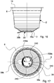
- FIG 16 illustrates still another version of the mixing element 320, differing from the versions disclosed above in that it comprises respective blades 322 which comprise an elongated, rigid tubular element, fixed to a respective central portion 321 of annular shape and rotatably and co-axially mounted on the nozzle 7, having respective supplying openings 323, obtained in the tubular wall of the central portion 321, one for each blade 322.
- respective blades 322 which comprise an elongated, rigid tubular element, fixed to a respective central portion 321 of annular shape and rotatably and co-axially mounted on the nozzle 7, having respective supplying openings 323, obtained in the tubular wall of the central portion 321, one for each blade 322.
- Each tubular element is provided with an exit opening 326 arranged at an external end of the blade 322 and further comprises an internal duct 327 to direct the jet L of fluid F coming from the supplying opening 323 to the exit opening 326.
- the exit opening 326 is obtained in a side wall of the blade 322 so as to eject a jet L of fluid F parallel to the base wall 3 of the capsule and transversally to a rotation axis Y of the mixing element 320, coinciding with the longitudinal axis X of the nozzle 7, tangentially to the blade 322 with respect to the rotation axis Y.
- the exit openings 326 of each blade are on opposite side walls to direct the jets L of fluid in parallel, but opposite directions, so as to rotate the mixing element 320.
- each blade comprises a plurality of exit openings obtained in the side wall of the blade to eject a plurality of mutually parallel jets.
- the plurality of exit openings of each blade are on opposite faces to direct the jets of fluid L in parallel, but opposite, directions.
- FIG 17 illustrates a still further version of the mixing element 420, similar to the version in Figure 16 , differing from the latter in that it comprises respective elongated, rigid, tubular blades 422 fixed to a respective central portion 421 of annular shape and rotatably and co-axially mounted on the nozzle 7, having respective supplying openings 423, obtained in the tubular wall of the central portion 421, one for each blade 422 .
- Each blade 422 has an end exit opening 426 obtained in the side wall of the blade 422 and a plurality of further exit openings 428 obtained in a bottom wall of the blade 422, each further exit opening facing the base wall 3 of the capsule 1.
- An internal duct 427 is arranged to direct the jet L of fluid F coming from the supplying opening 423 to the exit opening 426 and the further exit openings 428.
- the jet of fluid L ejected by the side exit opening 426 is parallel to the base wall 3 of the capsule, transversal to a rotation axis Y of the mixing element 420 and substantially tangential with respect to the rotation axis Y to rotate the mixing element 420 about the rotation axis Y.
- the jets of fluid L ejected by the further exit openings 426 instead face the bottom of the capsule 1.
- exit opening 426 and the further exit openings 428 determine a vortex flow of fluid inside the cavity 4, with jets facing also the bottom promoting the solubilization of not much or slowly soluble products that are typically deposited undissolved on the bottom.
- each blade comprises a plurality of exit openings obtained in the side wall of the blade to eject a plurality of mutually parallel jets and a plurality of further exit openings facing the bottom of the capsule.
- This version is advantageous when it is desired to create a vortex flow of fluid with distributed jets.
- the elongated stems 127, 128 shown in Figure 10 or the flaps 227 shown in Figure 11 may advantageously be applied to the mixing elements 320 and 420 shown in the Figures 14 and 15 , or to versions not illustrated thereof, disclosed above.
- One or more stop teeth 25, disclosed with reference to the mixing element 20 in Figure 1 may be advantageously applied also to the mixing elements 120, 220, 320, and 420 shown in the remaining Figures.
- Figures 12 and 13 illustrate a version of the capsule 1 differing from the embodiment disclosed above and shown in the Figures 1 to 9 , in that the nozzle 70 comprises a respective rigid and elongated tubular element having a longitudinal side wall 80 provided with an outflow opening 71 and a first end 78 provided with a first opening 73 arranged to engage with injection means of a brewing machine capable of dispensing the fluid F, flowingly connected via a first duct 74 to the outflow opening 71.
- Such version of nozzle does not comprise dispensing opening, second duct, and second opening.
- the nozzle further comprises a second end 79 having an external flange 79a opposite the first end 78.
- the external flange 79a abuts against an external surface of the base wall 3.
- the nozzle 70 is provided with a first portion 75 adjacent to the second end 79 and arranged to engage with interference and sealingly slide in the exit opening 31 of the base wall 3 so as to prevent the exit of the fluid and/or product from the cavity 5.
- the cross-sections of the nozzle 70, at the first portion 75, and of the exit opening 31 have a complementary shape.
- the first portion 75 is provided with a respective stop groove 85 and a respective supplying groove 82, similar to those disclosed with reference to Figure 1 .
- the nozzle 70 also comprises a second portion 76 adjacent to the first portion 75, interposed between the latter and the first end 78 and having a cross-section smaller than that of the first portion 75 and the exit opening 31 so as to allow the final product B exiting the cavity 5 through the above-mentioned exit opening 31, when in the dispensing step E the casing 2 is compressed and crushed until bringing the second portion 76 at the above-mentioned exit opening ( Figure 13 ).
- the beverage B contained in the capsule 1 may exit substantially by gravity and/or thrust by the compression and crushing of the capsule 1.
- the second portion 76 has a substantially circular cross-section, as the one of the first portion 75, but with a smaller diameter, so as not to abut against the exit opening 31.
- the longitudinal side wall 80 of the nozzle 70 at the second portion 76 and the exit opening 31 form the passage through which the final product B may exit.
- the shape of the cross-section of the second portion 76 may also be oval or polygonal, in any case, such as to make with the exit opening 31 a passage for the exit of the final product B.
- the second portion 76 allows the free sliding along the nozzle 70 of the mixing element 20 towards the covering element 19 under the thrust of the base wall 3 during the compression and crushing of the capsule 1 in the dispensing step E.
- the cavity 5 has to be connected to the outer environment to allow the inlet of the fluid F and the concomitant exit of the air contained therein, for example, suitably perforating the covering element 19.
- the brewing machine may be provided with suitable means for the perforation and exit of air.
- the base wall 3 of the capsule 1 comprises an edge or annular wall extending about the exit opening 31 and inside or outside of the cavity 5.
- the annular wall is intended to sealingly engage the longitudinal side wall 10 of the nozzle 7.
- the cross-sections of the nozzle 7 and of the annular wall are of a complementary shape.
- such version of the base wall 3 may be also applied to the version of the capsule 1 of the invention in Figure 12 and 13 , but in such case the cross-sections of the first portion 75 of the nozzle 70 and of the annular wall are of a complementary shape.
- the base wall is closed, i.e., not provided with the exit opening 31, and it comprises, besides to the annular wall projecting outside of the cavity 5, a bottom wall connected to the annular wall so as to form a compartment suitable to partially house the second end 9 of the nozzle 7.
- the bottom wall is easily frangible from the second end 9 of the nozzle 7 when the casing 2 is compressed and crushed.
- the bottom wall is obtained with a reduced wall thickness.
- the bottom wall may comprise a pre-incision line or a weakening portion, promoting the perforation by the nozzle 7.
- the external flange 9a of the nozzle 7 has an external surface which is provided with an annular groove with a triangular cross-section proximate to the second opening 16, which is suitable to direct the final product B when it exits the capsule 1 through the above-mentioned second opening 16.
- Such groove may aid in more accurately directing the final product B flow into the fruition container.
- annular groove may be implementable also in the external flange 79a of the nozzle 70 shown in the version in Figure 12 and 13 of the capsule 1 of the invention.
- the covering element 19 is fixed by welding to the nozzle 7 to create a fluid seal between the covering element 19 and the first end 8 of the nozzle 7.
Landscapes
- Chemical & Material Sciences (AREA)
- Chemical Kinetics & Catalysis (AREA)
- Engineering & Computer Science (AREA)
- Mechanical Engineering (AREA)
- Apparatus For Making Beverages (AREA)
- Packging For Living Organisms, Food Or Medicinal Products That Are Sensitive To Environmental Conditiond (AREA)
Claims (32)
- Capsule comprenant:- un boîtier (2) doté d'une paroi de base (3) et d'une paroi latérale (4) définissant une cavité (5) adaptée pour contenir un produit initial (P) à joindre à un fluide (F) pour fabriquer un produit final (B), dans lequel ledit boîtier comprend un bord (6);- un élément couvrant (19) fixé audit bord (6) pour fermer hermétiquement ladite cavité (5);- une buse (7 ; 70) comprenant une paroi latérale longitudinale (10; 80) et une première extrémité (8; 78) fixée audit élément couvrant (19) doté d'une première ouverture (13; 73) adaptée pour engager un moyen d'injection de fluide d'une machine à infusion, ladite paroi latérale longitudinale (10; 80) étant dotée d'au moins une ouverture d'écoulement (11; 71) reliée à ladite première ouverture (13; 73) par un premier conduit (14; 74) pour distribuer ledit fluide (F) dans ladite cavité (5) dans une étape d'injection (J);caractérisée en ce que ladite capsule comprend en outre:un élément de mélange (20; 120; 220; 320; 420) couplé de manière rotative à ladite buse (7; 70) sur ladite ouverture d'écoulement (11; 71) et formé de manière à détourner au moins un jet (L) de fluide (F) venant de ladite ouverture d'écoulement (11; 71) et à être tourné par ledit jet (L) autour de ladite buse (7; 70) de sorte à créer dans ladite cavité (5) un flux tourbillonnaire de fluide et de produit ;dans lequel ledit élément de mélange comprend une partie centrale (21; 121; 221, 321, 421) qui est couplée en rotation avec ladite buse (7; 70) et au moins une lame de forme allongée (22; 122; 222, 322, 422) fixée à ladite partie centrale (21; 121; 221, 321, 421) et s'étendant depuis ladite partie centrale (21) sensiblement radialement vers l'extérieur.
- Capsule selon la revendication 1, dans laquelle ledit élément de mélange (20; 120; 220, 320, 420) est rotatif autour d'un axe de rotation (Y) coïncidant avec un axe longitudinal de ladite buse (7; 70) et dans laquelle ladite partie centrale (21; 121; 221, 321, 421) présente une forme annulaire et est montée coaxialement sur ladite buse (7; 70) dans une configuration assemblée (W).
- Capsule selon la revendication 2, dans laquelle ladite partie centrale (21; 121; 221, 321, 421) comprend une ouverture d'alimentation (23; 123; 223, 323, 423) réalisée sur ladite lame (22; 122; 222, 322, 422) et reliée à ladite ouverture d'écoulement (11; 71) de sorte à générer un jet respectif (L) de fluide (F) et à transporter ledit jet (L) vers ladite lame (22; 122; 222, 322, 422).
- Capsule selon la revendication 2, dans laquelle ledit élément de mélange (20; 120; 220, 320, 420) comprend une pluralité de lames (22; 122; 222, 322, 422) qui sont fixées radialement à ladite partie centrale (21; 121; 221, 321, 421) et sont espacées angulairement les unes des autres, ladite partie centrale (21; 121; 221, 321, 421) comprenant une ouverture d'alimentation (23; 123; 223, 323, 423) pour chaque lame (22; 122; 222, 322, 422) afin de générer un jet respectif (L) de fluide (F) et de transporter ledit jet (L) vers chacune desdites lames (22; 122; 222, 322, 422).
- Capsule selon l'une quelconque des revendications précédentes, dans laquelle chaque lame (22; 122; 222) comprend une partie (22a) présentant une forme concave pour intercepter ledit jet (L) de fluide (F) venant de ladite ouverture d'alimentation (23; 123; 223).
- Capsule selon l'une quelconque des revendications 2 à 4, dans laquelle chaque lame (322; 422) comprend un élément tubulaire doté d'une ouverture de sortie (326; 426) agencée sur une extrémité externe de ladite lame (322; 422), et un conduit interne (327; 427) pour guider ledit jet (L) de fluide (F) venant de ladite ouverture d'alimentation (323; 423) à ladite ouverture de sortie (326; 426).
- Capsule selon la revendication 6, dans laquelle ladite ouverture de sortie (326; 426) est obtenue dans une paroi latérale de ladite lame (322; 422) de sorte à éjecter ledit jet (L) de fluide (F) parallèlement à ladite paroi de base (3) et transversalement et sensiblement tangentiellement à ladite lame (322; 422) par rapport à un axe de rotation (Y) dudit élément de mélange (320; 420).
- Capsule selon la revendication 7, et comprenant une paire de lames (322; 422) qui sont opposées l'une à l'autre, chaque lame (322; 422) étant dotée d'une ouverture de sortie respective (326; 426) sur des parois latérales opposées pour diriger lesdits jets (L) de fluide (F) le long de directions parallèles mais opposées.
- Capsule selon l'une quelconque des revendications 2 à 8, dans laquelle chaque lame (22; 122; 322; 422) comprend une paire respective de tiges allongées (127, 128) qui présentent une hauteur différente et qui sont transversalement fixées à ladite lame (22; 122; 322; 422), en particulier qui sont inclinées par rapport à un axe de rotation (Y) dudit élément de mélange ou dans lequel chaque lame (22; 122; 322; 422) comprend un volet respectif (227) avec une forme triangulaire fixée transversalement, en particulier orthogonalement à ladite lame (22; 222; 322; 422), une base dudit volet (227) étant fixée à ladite lame sur la longueur entière de ladite lame (22; 222; 322; 422).
- Capsule selon l'une quelconque des revendications 3 à 9, dans laquelle ladite buse (7; 70) comprend une rainure d'alimentation (12; 82) alimentée par ladite ouverture d'écoulement (11; 71), ledit élément de mélange (20; 120; 220; 320; 420) étant couplé à ladite buse (7; 70) dans ladite configuration assemblée (W) de telle manière que ladite ouverture d'alimentation (23; 123; 223; 323; 423) fasse face à ladite rainure d'alimentation (12; 82) et soit reliée à celle-ci pour recevoir ledit fluide (F).
- Capsule selon l'une quelconque des revendications 2 à 10, comprenant un moyen de verrouillage (15, 85, 25) pour restreindre élastiquement et de manière amovible ledit élément de mélange (20; 120; 220; 320; 420) à ladite buse (7; 70) dans ladite configuration assemblée (W) et pour permettre audit élément de mélange (20; 120; 220; 320; 420) de tourner librement autour de ladite buse (7; 70), dans laquelle ledit moyen de verrouillage comprend au moins une dent d'arrêt (25) associée à une partie centrale (21; 121; 221; 321; 421) dudit élément de mélange (20; 120; 220; 320; 420) et agencée pour engager élastiquement une rainure d'arrêt (15; 85) réalisée dans ladite buse (7; 70).
- Capsule selon l'une quelconque des revendications précédentes, dans laquelle ladite buse (7; 70) comprend une seconde extrémité (9; 79) opposée à ladite première extrémité (8; 78) et sortant au moins partiellement de ladite cavité (5) par une ouverture de sortie (31) réalisée dans ladite paroi de base (3), dans laquelle ladite seconde extrémité (9; 79) de ladite buse (7; 70) présente une bride externe (9a, 79a) qui bute, dans une configuration initiale (K) de ladite capsule (1), contre une surface externe de ladite paroi de base (3).
- Capsule selon la revendication 12, dans laquelle ladite capsule (1) comprend un élément de fermeture (39) fixé de manière amovible à ladite bride externe (9a, 79a) et/ou à une surface externe de ladite paroi de base (3).
- Capsule selon la revendication 12 ou 13, dans laquelle ladite seconde extrémité (9) est dotée d'une seconde ouverture (16) reliée par écoulement par un second conduit (17) à une ouverture de distribution (18) réalisée dans ladite paroi latérale longitudinale (10) de ladite buse (7), ladite ouverture de distribution (18), ledit second conduit (17) et ladite seconde ouverture (16) permettant audit produit final (B) de sortir de ladite cavité (5) et d'être distribué directement dans un récipient de collecte dans une étape de distribution (E), ledit premier conduit (14) et ledit second conduit (17) étant positionnés côte à côte et s'étendant sensiblement sur la longueur entière de ladite buse (7), ladite ouverture d'écoulement (11) étant réalisée à proximité de ladite seconde extrémité (9), ladite ouverture de distribution (18) étant réalisée à proximité de ladite première extrémité (8).
- Capsule selon la revendication 14 lorsqu'elle est dépendante de la revendication 13, et comprenant un produit solide (UP) contenu dans ledit second conduit (17) fermé par ledit élément de fermeture (39) et pouvant être distribuée directement dans ledit récipient de collecte par l'intermédiaire de ladite seconde ouverture (16) avant ladite étape de distribution (E).
- Capsule selon la revendication 15, dans laquelle ledit produit solide (UP) est constitué d'un seul élément ayant au moins une dimension qui est supérieure à, ou la même que, une largeur de ladite ouverture de distribution (18) de telle sorte que ladite ouverture de distribution (18) empêche ledit produit solide (UP) de sortir dudit second conduit (17) vers ladite cavité (5).
- Capsule selon la revendication 15, dans laquelle ledit produit solide (UP) est constitué d'une pluralité d'éléments ayant chacun au moins une dimension qui est supérieure à, ou la même que, une largeur de ladite ouverture de distribution (18) de telle sorte que ladite ouverture de distribution (18) empêche ledit produit solide (UP) de sortir dudit second conduit (17) vers ladite cavité (5).
- Capsule selon la revendication 17, dans laquelle lesdits éléments sont des éléments homogènes, comme, par exemple, des édulcorants ou des céréales, ou dans laquelle lesdits éléments sont des éléments non homogènes, comme, par exemple, un mélange d'édulcorants et de céréales.
- Capsule selon la revendication 14 lorsqu'elle est dépendante de la revendication 13, et comprenant un moyen d'interaction pour interagir avec ledit produit final (B) qui est contenu dans ledit second conduit (17) pour changer les caractéristiques dudit produit final (B) avant d'être distribué dans ledit récipient de collecte.
- Capsule selon la revendication 19, dans laquelle ledit moyen d'interaction comprend un élément pour créer un écoulement tourbillonnaire et/ou un élément perforé pour réaliser une fonction de filtrage ou, en variante, pour réduire ou éliminer une éventuelle mousse présente dans le produit final (B).
- Capsule selon la revendication 20, dans laquelle ledit élément pour créer un écoulement tourbillonnaire comprend un insert tubulaire allongé (528) ayant une paroi latérale longitudinale (529) pourvu d'une saillie hélicoïdale (530) s'étendant longitudinalement au moins le long d'une partie dudit insert (528), de préférence sur l'ensemble de l'insert (528).
- Capsule selon la revendication 21, dans laquelle ladite capsule (1) présente un espace annulaire (531) entre une paroi lisse (532) dudit second conduit (17) et ladite paroi latérale (529) dudit insert (528) munie de ladite saillie (539), ledit espace annulaire (531) présentant des canaux hélicoïdaux pour créer ledit écoulement tourbillonnaire.
- Capsule selon l'une quelconque des revendications précédentes, dans laquelle ledit boîtier (2) est déformable et/ou compressible le long d'une direction (A) qui est transversale, en particulier orthogonale à ladite paroi de base (3) afin de permettre audit produit final (B) de sortir de ladite cavité (5) et permettre à ladite buse (7; 70) de sortir davantage de ladite cavité (5).
- Capsule selon la revendication 23, lorsque la revendication 23 dépend de l'une quelconque des revendications 12 à 22, dans laquelle ladite buse (7; 70) est insérée et coulisse de manière étanche avec interférence dans ladite ouverture de sortie (31) lorsque ledit boîtier (2) est compressé et/ou écrasé ; et dans laquelle ladite buse (70) inclut une première partie (75) agencée pour engager avec interférence et coulisser dans ladite ouverture de sortie (31) de manière étanche de sorte à empêcher ledit fluide et/ou le produit de sortir de ladite cavité (5) et une seconde partie (76) qui est interposée entre ladite première partie (75) et ladite première extrémité (78) et dotée d'une section transversale qui est de sorte à permettre audit produit final (B) de sortir de ladite cavité par ladite ouverture de sortie (31) lorsque ledit boîtier (2) est compressé et/ou écrasé de sorte à mener ladite seconde partie (76) sur ladite ouverture de sortie (31).
- Capsule selon l'une quelconque des revendications précédentes, et comprenant un élément de recouvrement (19) fixé à un bord (6) dudit boîtier (2) pour fermer hermétiquement ladite cavité (5), ledit élément de recouvrement (19) étant perforable par ledit moyen d'injection de fluide de la machine à infusion pour permettre audit moyen d'injection de fluide de venir en prise avec ladite première ouverture (13) de ladite buse (7; 70).
- Capsule selon la revendication 25, dans laquelle ledit élément de recouvrement (19) est fixé par soudage à ladite première extrémité (8; 78) de ladite buse (7; 70).
- Capsule selon la revendication 13, ou l'une quelconque des revendications 14 à 25 lorsqu'elles sont dépendantes de la revendication 13, dans laquelle ledit élément de fermeture (39) comprend un bord de jonction (39a), ledit bord de jonction (39a) étant fixé pour une première partie (239a) à ladite surface externe de ladite paroi de base (3) par un joint de blocage et pour une seconde partie (239b) par un joint pelable, ledit joint de blocage nécessitant une force supérieure à celle dudit joint pelable pour détacher ledit joint d'assemblage (39a) à partir de ladite paroi de base (3), de manière à favoriser ledit détachement de ladite seconde partie (239b) avant ledit détachement de la première partie (239a).
- Capsule selon la revendication 27, dans laquelle ladite première partie (239a) s'étend dans un premier intervalle angulaire compris entre 80° et 110°, en particulier de préférence 100°, et ladite deuxième partie (239b) s'étend dans un second intervalle angulaire qui est complémentaire audit premier intervalle angulaire, ladite première partie (239a) et ladite seconde partie (239b) s'étendant sur l'ensemble du bord de jonction (139a).
- Capsule selon la revendication 27 ou 28, dans laquelle ladite deuxième partie (239b) comprend un moyen favorisant le détachement comprenant au moins une partie de détachement (240) à laquelle ladite seconde partie (239b) a une forme sensiblement en "V" ou en forme de coin pour faciliter une séparation graduelle et progressive du bord de jonction (139a) à partir de la paroi de base (3).
- Capsule selon la revendication 29, dans laquelle ladite première partie (239a) est dépourvue dudit moyen favorisant le détachement.
- Capsule selon la revendication 29 ou 30, dans laquelle ledit moyen favorisant le détachement comprenant une pluralité de parties de détachement (240) qui sont angulairement équidistants dans ladite seconde partie (239b).
- Capsule selon l'une quelconque des revendications 27 à 31, dans laquelle ledit élément de fermeture (39) comprend une languette allongée (39b) s'étendant vers l'extérieur à partir d'une partie de liaison du bord de jonction (39a) qui s'étend à partir de ladite première partie (239a).
Applications Claiming Priority (4)
| Application Number | Priority Date | Filing Date | Title |
|---|---|---|---|
| IT000327A ITMO20120327A1 (it) | 2012-12-27 | 2012-12-27 | Capsula per bevande |
| IT000296A ITMO20130296A1 (it) | 2013-10-17 | 2013-10-17 | Capsula per bevande |
| IT000320A ITMO20130320A1 (it) | 2013-11-20 | 2013-11-20 | Capsula per bevande |
| PCT/IB2013/061267 WO2014102702A1 (fr) | 2012-12-27 | 2013-12-23 | Capsule pour boissons |
Publications (2)
| Publication Number | Publication Date |
|---|---|
| EP2945885A1 EP2945885A1 (fr) | 2015-11-25 |
| EP2945885B1 true EP2945885B1 (fr) | 2018-03-14 |
Family
ID=50070625
Family Applications (1)
| Application Number | Title | Priority Date | Filing Date |
|---|---|---|---|
| EP13828869.1A Not-in-force EP2945885B1 (fr) | 2012-12-27 | 2013-12-23 | Capsule pour boissons |
Country Status (7)
| Country | Link |
|---|---|
| US (1) | US9399547B2 (fr) |
| EP (1) | EP2945885B1 (fr) |
| JP (1) | JP6290252B2 (fr) |
| CN (1) | CN104955744B (fr) |
| CA (1) | CA2895646A1 (fr) |
| ES (1) | ES2663123T3 (fr) |
| WO (1) | WO2014102702A1 (fr) |
Families Citing this family (66)
| Publication number | Priority date | Publication date | Assignee | Title |
|---|---|---|---|---|
| US11832755B2 (en) * | 2007-07-13 | 2023-12-05 | Adrian Rivera | Brewing material container for a beverage brewer |
| US10722066B2 (en) * | 2010-12-04 | 2020-07-28 | Adrian Rivera | Windowed single serving brewing material holder |
| US10071851B2 (en) | 2010-07-12 | 2018-09-11 | Robert Bao Vu | Apparatus and products for producing beverages, and methods for making and using same |
| DK3521210T3 (da) | 2010-07-22 | 2020-04-14 | K Fee System Gmbh | Portionskapsel med stregkode |
| DE102012105282A1 (de) | 2012-06-18 | 2013-12-19 | K-Fee System Gmbh | Portionskapsel und Verfahren zur Herstellung eines Getränks mit einer Portionskapsel |
| DE102012223291A1 (de) | 2012-12-14 | 2014-06-18 | K-Fee System Gmbh | Portionskapsel und Verfahren zur Herstellung eines Getränks mit einer Portionskapsel |
| USD756785S1 (en) * | 2013-07-10 | 2016-05-24 | Sarong Societa' Per Azioni | Capsule |
| RU2651261C2 (ru) * | 2013-07-10 | 2018-04-18 | Нестек С.А. | Капсула для приготовления напитка |
| JP2016537146A (ja) * | 2013-09-09 | 2016-12-01 | ネステク ソシエテ アノニム | 粘性飲料又は食品製品を調製するためのカプセル、方法及びシステム |
| JP6434042B2 (ja) * | 2014-02-14 | 2018-12-05 | レミントン デザインズ リミテッド ライアビリティ カンパニー | 飲料抽出装置および飲料の抽出に関連する方法 |
| US10442610B2 (en) | 2014-03-11 | 2019-10-15 | Starbucks Corporation | Pod-based restrictors and methods |
| US8960999B1 (en) | 2014-03-28 | 2015-02-24 | Gudpod Holdings, Llc | System for mixing beverages and method of doing the same |
| US20160353919A1 (en) * | 2014-10-06 | 2016-12-08 | Remington Designs, Llc | Beverage brewing systems and methods for using the same |
| CN107105927B (zh) | 2014-11-17 | 2021-04-06 | 艾匹克控股有限责任公司 | 填充有单次服务份量的有待与基础液体相组合以便制备液体产品的液体成分的可抛弃式盒 |
| EP3221220A4 (fr) * | 2014-11-20 | 2018-07-18 | Starbucks Corporation | Dosette pour machine à boisson |
| RU2017133486A (ru) | 2015-02-27 | 2019-03-27 | К-Фее Зюстем Гмбх | Порционная капсула с прикрепленным посредством термосварки фильтрующим элементом |
| US10111554B2 (en) | 2015-03-20 | 2018-10-30 | Meltz, LLC | Systems for and methods of controlled liquid food or beverage product creation |
| US10314320B2 (en) | 2015-03-20 | 2019-06-11 | Meltz, LLC | Systems for controlled liquid food or beverage product creation |
| US9487348B2 (en) | 2015-03-20 | 2016-11-08 | Meltz, LLC | Systems for and methods of providing support for displaceable frozen contents in beverage and food receptacles |
| US9346611B1 (en) | 2015-03-20 | 2016-05-24 | Meltz, LLC | Apparatus and processes for creating a consumable liquid food or beverage product from frozen contents |
| JP6580714B2 (ja) | 2015-06-10 | 2019-09-25 | ケイ‐フィー システム ゲーエムベーハー | 3層不織布を用いたポーションカプセル |
| CN107848699A (zh) | 2015-07-13 | 2018-03-27 | K-Fee系统股份有限公司 | 具有切口的过滤元件 |
| DE102015115250A1 (de) * | 2015-09-10 | 2017-03-16 | Pester Pac Automation Gmbh | Verwendung einer Verpackung |
| MX2018002991A (es) | 2015-09-18 | 2018-05-02 | K Fee System Gmbh | Adaptador para una capsula monodosis. |
| ITUB20154199A1 (it) | 2015-10-07 | 2017-04-07 | Carpigiani Group Ali Spa | Macchina e metodo per la realizzazione di prodotti liquidi e semiliquidi del tipo caldo o freddo. |
| AU2016358449B2 (en) * | 2015-11-25 | 2021-12-02 | Cambdev Limited | Coffee dispensing apparatus |
| US20180370720A1 (en) * | 2016-02-09 | 2018-12-27 | Nectec S.A. | A beverage capsule |
| USD800497S1 (en) | 2016-02-26 | 2017-10-24 | Bartesian Inc. | Beverage capsule |
| USD812952S1 (en) | 2016-02-26 | 2018-03-20 | Bartesian Inc. | Beverage machine |
| USD843765S1 (en) | 2016-02-26 | 2019-03-26 | Bartesian Inc. | Beverage machine |
| CN111166174B (zh) * | 2016-03-01 | 2022-12-16 | 贝塔什股份有限公司 | 饮料机和与饮料机一起使用的胶囊 |
| EP3471550A4 (fr) | 2016-06-16 | 2020-02-26 | Sigma Phase, Corp. | Système pour fournir une portion unique d'une confiserie glacée |
| IL246656A0 (en) * | 2016-07-07 | 2016-09-29 | Solo Gelato Ltd | System and capsule for making an edible product |
| IT201600074471A1 (it) * | 2016-07-15 | 2018-01-15 | Ali Group Srl Carpigiani | Macchina e metodo per la produzione di prodotti liquidi e semiliquidi del settore gelateria, pasticceria o ristorazione. |
| WO2018053207A1 (fr) * | 2016-09-15 | 2018-03-22 | Gudpod Corp. | Système permettant de mélanger des boissons et procédé associé |
| IT201600100869A1 (it) | 2016-10-07 | 2018-04-07 | Ali Group Srl Carpigiani | Metodo e sistema di pulizia di una macchina per la realizzazione di prodotti alimentari liquidi e/o semiliquidi del settore gelateria, pasticceria o ristorazione |
| CN109008640A (zh) * | 2017-04-08 | 2018-12-18 | 聂世林 | 快速制备饮料的容器 |
| IT201700043975A1 (it) | 2017-04-21 | 2018-10-21 | Ali Group Srl Carpigiani | Macchina e metodo per la produzione di prodotti liquidi e semiliquidi del settore gelateria. |
| CA3061607A1 (fr) | 2017-04-27 | 2018-11-01 | Meltz, LLC | Procede d'extraction centrifuge et appareil apte a la mise en oeuvre de ce procede |
| IT201700047824A1 (it) * | 2017-05-03 | 2018-11-03 | Sarong Spa | Capsula per bevande |
| GB2563394A (en) * | 2017-06-12 | 2018-12-19 | Doctor T Company Ltd | Brewing Capsule Structure |
| JP7072927B2 (ja) * | 2017-12-17 | 2022-05-23 | アドヴァンター・イノヴェイションズ・ピーティイー・リミテッド | カプセルベースの食品混合/排出システム、およびそれに関連する方法 |
| EP3536637B1 (fr) * | 2018-03-05 | 2020-09-16 | Nootrie AG | Capsule pour préparer une boisson |
| WO2019175720A1 (fr) * | 2018-03-16 | 2019-09-19 | Do Nascimento Da Camara Pestana Tomas Abecasis | Moyens de dissolution mécanique, ensemble et capsule pour l'extraction de jus en poudre ou concentré |
| USD890569S1 (en) | 2018-06-19 | 2020-07-21 | Bartesian Inc. | Beverage capsule receiving adaptor |
| IT201800007006A1 (it) * | 2018-07-06 | 2020-01-06 | Capsula per produrre un prodotto alimentare | |
| US12227323B2 (en) | 2018-07-27 | 2025-02-18 | Gcs German Capsule Solution Gmbh | Method for producing a portion capsule |
| US10612835B2 (en) | 2018-08-17 | 2020-04-07 | Sigma Phase, Corp. | Rapidly cooling food and drinks |
| US11470855B2 (en) | 2018-08-17 | 2022-10-18 | Coldsnap, Corp. | Providing single servings of cooled foods and drinks |
| US10543978B1 (en) | 2018-08-17 | 2020-01-28 | Sigma Phase, Corp. | Rapidly cooling food and drinks |
| USD893293S1 (en) | 2018-08-24 | 2020-08-18 | Bartesian Inc. | Beverage capsule |
| WO2020044146A1 (fr) * | 2018-08-30 | 2020-03-05 | Sarong Societa' Per Azioni | Capsule |
| US12459728B2 (en) | 2018-11-22 | 2025-11-04 | Gcs German Capsule Solution Gmbh | Seal for a single serve capsule |
| US11724849B2 (en) | 2019-06-07 | 2023-08-15 | Cometeer, Inc. | Packaging and method for single serve beverage product |
| KR20220069932A (ko) | 2019-09-27 | 2022-05-27 | 니폰 제온 가부시키가이샤 | 감방사선성 수지 조성물 |
| US11337438B2 (en) | 2020-01-15 | 2022-05-24 | Coldsnap, Corp. | Rapidly cooling food and drinks |
| USD969547S1 (en) | 2020-04-16 | 2022-11-15 | Sarong Societa' Per Azioni | Coffee capsule |
| TW202202790A (zh) | 2020-06-01 | 2022-01-16 | 美商寇德斯納普公司 | 用於快速冷卻食物及飲料的冷凍系統 |
| US20210386236A1 (en) * | 2020-06-12 | 2021-12-16 | Nexe Innovations Inc. | Faceplate for improved extraction of beverage material |
| CN111790282B (zh) * | 2020-06-24 | 2022-12-23 | 阜阳天祥食品科技有限公司 | 一种芝麻调和油调制设备 |
| CN112191140B (zh) * | 2020-09-17 | 2022-08-19 | 王顿 | 食物胶囊、搅拌装置和食物胶囊使用方法 |
| US11805934B1 (en) * | 2020-10-21 | 2023-11-07 | Adrian Rivera | Brewing material lid and container for a beverage brewer |
| US11827402B2 (en) | 2021-02-02 | 2023-11-28 | Coldsnap, Corp. | Filling aluminum cans aseptically |
| CN115430534A (zh) * | 2022-07-28 | 2022-12-06 | 中国核电工程有限公司 | 一种用于事故泄压排放的旋转喷射装置 |
| KR102567346B1 (ko) * | 2023-03-03 | 2023-08-16 | (주)대명에스이에스 | 급수 혼합성이 향상되는 물탱크 |
| US12599942B2 (en) * | 2023-03-31 | 2026-04-14 | Recycap Technologies, S.L. | Extraction device and mechanisms, and use in recycling beverage capsules |
Family Cites Families (21)
| Publication number | Priority date | Publication date | Assignee | Title |
|---|---|---|---|---|
| JPH0349633Y2 (fr) * | 1987-09-03 | 1991-10-23 | ||
| US20070196402A1 (en) | 2006-01-27 | 2007-08-23 | L'oreal | Method of preparing a cosmetic composition, and an assembly and a refill for implementing such a method |
| NL1031177C2 (nl) | 2006-02-17 | 2007-08-20 | Meccano Asia Ltd | Verpakking en inrichting voor het bereiden van een drank. |
| US7947316B2 (en) * | 2006-08-04 | 2011-05-24 | The Coca-Cola Company | Pod for dispersible materials |
| ITMO20070143A1 (it) * | 2007-04-27 | 2008-10-28 | Massimiliano Pineschi | Capsula per contenere dosi di bevande solubili |
| CN102015488B (zh) | 2008-04-30 | 2013-09-11 | 雀巢产品技术援助有限公司 | 容纳有饮料配料并具有进口侧隔膜的密封胶囊 |
| EP2384305A1 (fr) * | 2009-01-05 | 2011-11-09 | Nestec S.A. | Capsule avec commande d'écoulement et élément de filtration |
| PT2236437E (pt) * | 2009-03-31 | 2012-04-13 | Nestec Sa | Cápsula com filtro para preparar uma composição nutricional ou alimentícia líquida e sistema de produção de bebida correspondente |
| CN102482032B (zh) | 2009-06-17 | 2014-12-10 | 皇家戴维艾格伯茨有限公司 | 用于制备饮料的系统、方法和包囊 |
| KR101542293B1 (ko) | 2009-11-12 | 2015-08-06 | 제너레이션 아이.디.이.에이., 엘엘씨 | 카트리지 장치 |
| US20110244108A1 (en) | 2010-04-02 | 2011-10-06 | Rabin Michael David | Container for single-serve liquid/solid food product |
| TW201200433A (en) | 2010-05-06 | 2012-01-01 | Brita Gmbh | Container and device with such a container |
| DE102010030988B4 (de) | 2010-07-06 | 2012-04-05 | Brita Gmbh | Behälter |
| EP2412645A1 (fr) | 2010-07-28 | 2012-02-01 | Samar Technologies Ltd. | Capsule d'infusion pré-remplie, procédé de fabrication et dispositif associé |
| DE102011012881A1 (de) | 2010-09-22 | 2012-03-22 | Krüger Gmbh & Co. Kg | Portionskapsel und Verfahren zur Herstellung eines Getränks mit einer Portionskapsel |
| EP2444339A1 (fr) * | 2010-10-25 | 2012-04-25 | Nestec S.A. | Capsule pour la préparation d'une boisson |
| IT1403541B1 (it) * | 2011-01-31 | 2013-10-31 | Sarong Spa | Macchina erogatrice per bevande |
| ES1075815Y (es) * | 2011-10-25 | 2012-03-08 | Inventos Para Sist S Vending S L | Capsula monodosis para maquinas de cafe espresso |
| EP2802519B1 (fr) | 2012-01-12 | 2016-09-07 | Sarong Societa' Per Azioni | Capsule pour boisson |
| ITMO20120056A1 (it) | 2012-03-07 | 2013-09-08 | Sarong Spa | Capsula per bevande |
| ES2613854T3 (es) | 2012-04-17 | 2017-05-26 | Sarong Societa' Per Azioni | Cápsula y máquina dispensadora para bebidas |
-
2013
- 2013-12-23 CA CA2895646A patent/CA2895646A1/fr not_active Abandoned
- 2013-12-23 ES ES13828869.1T patent/ES2663123T3/es active Active
- 2013-12-23 EP EP13828869.1A patent/EP2945885B1/fr not_active Not-in-force
- 2013-12-23 WO PCT/IB2013/061267 patent/WO2014102702A1/fr not_active Ceased
- 2013-12-23 JP JP2015550185A patent/JP6290252B2/ja not_active Expired - Fee Related
- 2013-12-23 CN CN201380071283.2A patent/CN104955744B/zh not_active Expired - Fee Related
- 2013-12-23 US US14/655,157 patent/US9399547B2/en not_active Expired - Fee Related
Also Published As
| Publication number | Publication date |
|---|---|
| JP2016508759A (ja) | 2016-03-24 |
| WO2014102702A1 (fr) | 2014-07-03 |
| CA2895646A1 (fr) | 2014-07-03 |
| JP6290252B2 (ja) | 2018-03-07 |
| ES2663123T3 (es) | 2018-04-11 |
| CN104955744A (zh) | 2015-09-30 |
| CN104955744B (zh) | 2017-04-12 |
| EP2945885A1 (fr) | 2015-11-25 |
| US9399547B2 (en) | 2016-07-26 |
| US20150329282A1 (en) | 2015-11-19 |
Similar Documents
| Publication | Publication Date | Title |
|---|---|---|
| EP2945885B1 (fr) | Capsule pour boissons | |
| EP2941392B1 (fr) | Capsule pour boissons | |
| CA2864845C (fr) | Capsule pour boisson | |
| CN101977827B (zh) | 用于制备液体的包括可刺穿的输出壁的料盒 | |
| EP2838814B1 (fr) | Capsule et machine de distribution pour boissons | |
| RU2735591C2 (ru) | Система и капсулы для приготовления напитков | |
| EP2330953B1 (fr) | Procédé de préparation par centrifugation d'un liquide alimentaire contenu dans une capsule et système conçu pour un tel procédé | |
| EP2590876B1 (fr) | Capsule de préparation de produits alimentaires pour machine de préparation d'aliments | |
| JP6644054B2 (ja) | 飲料を調製するためのパック及びマシン | |
| CA2629224C (fr) | Ingredient de boisson contenant une capsule possedant plusieurs compartiments | |
| CN104703517B (zh) | 基于胶囊的食物制备系统 | |
| JP2019506199A (ja) | カプセルを備えるカプセル・アッセンブリおよび前記カプセルを開口させるよう構成されるコンベヤー・キャップ | |
| JP2017529130A (ja) | 食品又は飲料を調製するためのパック | |
| ITMO20120327A1 (it) | Capsula per bevande |
Legal Events
| Date | Code | Title | Description |
|---|---|---|---|
| PUAI | Public reference made under article 153(3) epc to a published international application that has entered the european phase |
Free format text: ORIGINAL CODE: 0009012 |
|
| 17P | Request for examination filed |
Effective date: 20150727 |
|
| AK | Designated contracting states |
Kind code of ref document: A1 Designated state(s): AL AT BE BG CH CY CZ DE DK EE ES FI FR GB GR HR HU IE IS IT LI LT LU LV MC MK MT NL NO PL PT RO RS SE SI SK SM TR |
|
| AX | Request for extension of the european patent |
Extension state: BA ME |
|
| DAX | Request for extension of the european patent (deleted) | ||
| GRAP | Despatch of communication of intention to grant a patent |
Free format text: ORIGINAL CODE: EPIDOSNIGR1 |
|
| INTG | Intention to grant announced |
Effective date: 20170329 |
|
| GRAJ | Information related to disapproval of communication of intention to grant by the applicant or resumption of examination proceedings by the epo deleted |
Free format text: ORIGINAL CODE: EPIDOSDIGR1 |
|
| INTC | Intention to grant announced (deleted) | ||
| GRAP | Despatch of communication of intention to grant a patent |
Free format text: ORIGINAL CODE: EPIDOSNIGR1 |
|
| INTG | Intention to grant announced |
Effective date: 20170928 |
|
| GRAJ | Information related to disapproval of communication of intention to grant by the applicant or resumption of examination proceedings by the epo deleted |
Free format text: ORIGINAL CODE: EPIDOSDIGR1 |
|
| GRAR | Information related to intention to grant a patent recorded |
Free format text: ORIGINAL CODE: EPIDOSNIGR71 |
|
| GRAS | Grant fee paid |
Free format text: ORIGINAL CODE: EPIDOSNIGR3 |
|
| GRAA | (expected) grant |
Free format text: ORIGINAL CODE: 0009210 |
|
| INTC | Intention to grant announced (deleted) | ||
| INTG | Intention to grant announced |
Effective date: 20180201 |
|
| AK | Designated contracting states |
Kind code of ref document: B1 Designated state(s): AL AT BE BG CH CY CZ DE DK EE ES FI FR GB GR HR HU IE IS IT LI LT LU LV MC MK MT NL NO PL PT RO RS SE SI SK SM TR |
|
| REG | Reference to a national code |
Ref country code: GB Ref legal event code: FG4D |
|
| REG | Reference to a national code |
Ref country code: CH Ref legal event code: EP Ref country code: AT Ref legal event code: REF Ref document number: 978666 Country of ref document: AT Kind code of ref document: T Effective date: 20180315 |
|
| REG | Reference to a national code |
Ref country code: IE Ref legal event code: FG4D |
|
| REG | Reference to a national code |
Ref country code: ES Ref legal event code: FG2A Ref document number: 2663123 Country of ref document: ES Kind code of ref document: T3 Effective date: 20180411 |
|
| REG | Reference to a national code |
Ref country code: DE Ref legal event code: R096 Ref document number: 602013034501 Country of ref document: DE |
|
| REG | Reference to a national code |
Ref country code: NL Ref legal event code: MP Effective date: 20180314 |
|
| REG | Reference to a national code |
Ref country code: LT Ref legal event code: MG4D |
|
| PG25 | Lapsed in a contracting state [announced via postgrant information from national office to epo] |
Ref country code: FI Free format text: LAPSE BECAUSE OF FAILURE TO SUBMIT A TRANSLATION OF THE DESCRIPTION OR TO PAY THE FEE WITHIN THE PRESCRIBED TIME-LIMIT Effective date: 20180314 Ref country code: LT Free format text: LAPSE BECAUSE OF FAILURE TO SUBMIT A TRANSLATION OF THE DESCRIPTION OR TO PAY THE FEE WITHIN THE PRESCRIBED TIME-LIMIT Effective date: 20180314 Ref country code: CY Free format text: LAPSE BECAUSE OF FAILURE TO SUBMIT A TRANSLATION OF THE DESCRIPTION OR TO PAY THE FEE WITHIN THE PRESCRIBED TIME-LIMIT Effective date: 20180314 Ref country code: NO Free format text: LAPSE BECAUSE OF FAILURE TO SUBMIT A TRANSLATION OF THE DESCRIPTION OR TO PAY THE FEE WITHIN THE PRESCRIBED TIME-LIMIT Effective date: 20180614 Ref country code: HR Free format text: LAPSE BECAUSE OF FAILURE TO SUBMIT A TRANSLATION OF THE DESCRIPTION OR TO PAY THE FEE WITHIN THE PRESCRIBED TIME-LIMIT Effective date: 20180314 |
|
| REG | Reference to a national code |
Ref country code: AT Ref legal event code: MK05 Ref document number: 978666 Country of ref document: AT Kind code of ref document: T Effective date: 20180314 |
|
| PG25 | Lapsed in a contracting state [announced via postgrant information from national office to epo] |
Ref country code: BG Free format text: LAPSE BECAUSE OF FAILURE TO SUBMIT A TRANSLATION OF THE DESCRIPTION OR TO PAY THE FEE WITHIN THE PRESCRIBED TIME-LIMIT Effective date: 20180614 Ref country code: RS Free format text: LAPSE BECAUSE OF FAILURE TO SUBMIT A TRANSLATION OF THE DESCRIPTION OR TO PAY THE FEE WITHIN THE PRESCRIBED TIME-LIMIT Effective date: 20180314 Ref country code: SE Free format text: LAPSE BECAUSE OF FAILURE TO SUBMIT A TRANSLATION OF THE DESCRIPTION OR TO PAY THE FEE WITHIN THE PRESCRIBED TIME-LIMIT Effective date: 20180314 Ref country code: LV Free format text: LAPSE BECAUSE OF FAILURE TO SUBMIT A TRANSLATION OF THE DESCRIPTION OR TO PAY THE FEE WITHIN THE PRESCRIBED TIME-LIMIT Effective date: 20180314 Ref country code: GR Free format text: LAPSE BECAUSE OF FAILURE TO SUBMIT A TRANSLATION OF THE DESCRIPTION OR TO PAY THE FEE WITHIN THE PRESCRIBED TIME-LIMIT Effective date: 20180615 |
|
| PG25 | Lapsed in a contracting state [announced via postgrant information from national office to epo] |
Ref country code: EE Free format text: LAPSE BECAUSE OF FAILURE TO SUBMIT A TRANSLATION OF THE DESCRIPTION OR TO PAY THE FEE WITHIN THE PRESCRIBED TIME-LIMIT Effective date: 20180314 Ref country code: NL Free format text: LAPSE BECAUSE OF FAILURE TO SUBMIT A TRANSLATION OF THE DESCRIPTION OR TO PAY THE FEE WITHIN THE PRESCRIBED TIME-LIMIT Effective date: 20180314 Ref country code: RO Free format text: LAPSE BECAUSE OF FAILURE TO SUBMIT A TRANSLATION OF THE DESCRIPTION OR TO PAY THE FEE WITHIN THE PRESCRIBED TIME-LIMIT Effective date: 20180314 Ref country code: PL Free format text: LAPSE BECAUSE OF FAILURE TO SUBMIT A TRANSLATION OF THE DESCRIPTION OR TO PAY THE FEE WITHIN THE PRESCRIBED TIME-LIMIT Effective date: 20180314 Ref country code: AL Free format text: LAPSE BECAUSE OF FAILURE TO SUBMIT A TRANSLATION OF THE DESCRIPTION OR TO PAY THE FEE WITHIN THE PRESCRIBED TIME-LIMIT Effective date: 20180314 |
|
| PG25 | Lapsed in a contracting state [announced via postgrant information from national office to epo] |
Ref country code: AT Free format text: LAPSE BECAUSE OF FAILURE TO SUBMIT A TRANSLATION OF THE DESCRIPTION OR TO PAY THE FEE WITHIN THE PRESCRIBED TIME-LIMIT Effective date: 20180314 Ref country code: SK Free format text: LAPSE BECAUSE OF FAILURE TO SUBMIT A TRANSLATION OF THE DESCRIPTION OR TO PAY THE FEE WITHIN THE PRESCRIBED TIME-LIMIT Effective date: 20180314 Ref country code: SM Free format text: LAPSE BECAUSE OF FAILURE TO SUBMIT A TRANSLATION OF THE DESCRIPTION OR TO PAY THE FEE WITHIN THE PRESCRIBED TIME-LIMIT Effective date: 20180314 Ref country code: CZ Free format text: LAPSE BECAUSE OF FAILURE TO SUBMIT A TRANSLATION OF THE DESCRIPTION OR TO PAY THE FEE WITHIN THE PRESCRIBED TIME-LIMIT Effective date: 20180314 |
|
| REG | Reference to a national code |
Ref country code: DE Ref legal event code: R097 Ref document number: 602013034501 Country of ref document: DE |
|
| PG25 | Lapsed in a contracting state [announced via postgrant information from national office to epo] |
Ref country code: PT Free format text: LAPSE BECAUSE OF FAILURE TO SUBMIT A TRANSLATION OF THE DESCRIPTION OR TO PAY THE FEE WITHIN THE PRESCRIBED TIME-LIMIT Effective date: 20180716 |
|
| PLBE | No opposition filed within time limit |
Free format text: ORIGINAL CODE: 0009261 |
|
| STAA | Information on the status of an ep patent application or granted ep patent |
Free format text: STATUS: NO OPPOSITION FILED WITHIN TIME LIMIT |
|
| PG25 | Lapsed in a contracting state [announced via postgrant information from national office to epo] |
Ref country code: DK Free format text: LAPSE BECAUSE OF FAILURE TO SUBMIT A TRANSLATION OF THE DESCRIPTION OR TO PAY THE FEE WITHIN THE PRESCRIBED TIME-LIMIT Effective date: 20180314 |
|
| 26N | No opposition filed |
Effective date: 20181217 |
|
| PG25 | Lapsed in a contracting state [announced via postgrant information from national office to epo] |
Ref country code: SI Free format text: LAPSE BECAUSE OF FAILURE TO SUBMIT A TRANSLATION OF THE DESCRIPTION OR TO PAY THE FEE WITHIN THE PRESCRIBED TIME-LIMIT Effective date: 20180314 |
|
| PG25 | Lapsed in a contracting state [announced via postgrant information from national office to epo] |
Ref country code: LU Free format text: LAPSE BECAUSE OF NON-PAYMENT OF DUE FEES Effective date: 20181223 Ref country code: MC Free format text: LAPSE BECAUSE OF FAILURE TO SUBMIT A TRANSLATION OF THE DESCRIPTION OR TO PAY THE FEE WITHIN THE PRESCRIBED TIME-LIMIT Effective date: 20180314 |
|
| REG | Reference to a national code |
Ref country code: IE Ref legal event code: MM4A |
|
| REG | Reference to a national code |
Ref country code: BE Ref legal event code: MM Effective date: 20181231 |
|
| PG25 | Lapsed in a contracting state [announced via postgrant information from national office to epo] |
Ref country code: IE Free format text: LAPSE BECAUSE OF NON-PAYMENT OF DUE FEES Effective date: 20181223 |
|
| PG25 | Lapsed in a contracting state [announced via postgrant information from national office to epo] |
Ref country code: BE Free format text: LAPSE BECAUSE OF NON-PAYMENT OF DUE FEES Effective date: 20181231 |
|
| PG25 | Lapsed in a contracting state [announced via postgrant information from national office to epo] |
Ref country code: MT Free format text: LAPSE BECAUSE OF NON-PAYMENT OF DUE FEES Effective date: 20181223 |
|
| PGFP | Annual fee paid to national office [announced via postgrant information from national office to epo] |
Ref country code: IT Payment date: 20191231 Year of fee payment: 7 Ref country code: FR Payment date: 20191220 Year of fee payment: 7 |
|
| PG25 | Lapsed in a contracting state [announced via postgrant information from national office to epo] |
Ref country code: TR Free format text: LAPSE BECAUSE OF FAILURE TO SUBMIT A TRANSLATION OF THE DESCRIPTION OR TO PAY THE FEE WITHIN THE PRESCRIBED TIME-LIMIT Effective date: 20180314 |
|
| PGFP | Annual fee paid to national office [announced via postgrant information from national office to epo] |
Ref country code: CH Payment date: 20191220 Year of fee payment: 7 |
|
| PGFP | Annual fee paid to national office [announced via postgrant information from national office to epo] |
Ref country code: GB Payment date: 20191220 Year of fee payment: 7 Ref country code: ES Payment date: 20200114 Year of fee payment: 7 Ref country code: DE Payment date: 20200102 Year of fee payment: 7 |
|
| PG25 | Lapsed in a contracting state [announced via postgrant information from national office to epo] |
Ref country code: HU Free format text: LAPSE BECAUSE OF FAILURE TO SUBMIT A TRANSLATION OF THE DESCRIPTION OR TO PAY THE FEE WITHIN THE PRESCRIBED TIME-LIMIT; INVALID AB INITIO Effective date: 20131223 Ref country code: MK Free format text: LAPSE BECAUSE OF NON-PAYMENT OF DUE FEES Effective date: 20180314 |
|
| PG25 | Lapsed in a contracting state [announced via postgrant information from national office to epo] |
Ref country code: IS Free format text: LAPSE BECAUSE OF FAILURE TO SUBMIT A TRANSLATION OF THE DESCRIPTION OR TO PAY THE FEE WITHIN THE PRESCRIBED TIME-LIMIT Effective date: 20180714 |
|
| REG | Reference to a national code |
Ref country code: DE Ref legal event code: R119 Ref document number: 602013034501 Country of ref document: DE |
|
| REG | Reference to a national code |
Ref country code: CH Ref legal event code: PL |
|
| GBPC | Gb: european patent ceased through non-payment of renewal fee |
Effective date: 20201223 |
|
| PG25 | Lapsed in a contracting state [announced via postgrant information from national office to epo] |
Ref country code: FR Free format text: LAPSE BECAUSE OF NON-PAYMENT OF DUE FEES Effective date: 20201231 Ref country code: IT Free format text: LAPSE BECAUSE OF NON-PAYMENT OF DUE FEES Effective date: 20201223 |
|
| PG25 | Lapsed in a contracting state [announced via postgrant information from national office to epo] |
Ref country code: LI Free format text: LAPSE BECAUSE OF NON-PAYMENT OF DUE FEES Effective date: 20201231 Ref country code: CH Free format text: LAPSE BECAUSE OF NON-PAYMENT OF DUE FEES Effective date: 20201231 Ref country code: GB Free format text: LAPSE BECAUSE OF NON-PAYMENT OF DUE FEES Effective date: 20201223 Ref country code: DE Free format text: LAPSE BECAUSE OF NON-PAYMENT OF DUE FEES Effective date: 20210701 |
|
| REG | Reference to a national code |
Ref country code: ES Ref legal event code: FD2A Effective date: 20220411 |
|
| PG25 | Lapsed in a contracting state [announced via postgrant information from national office to epo] |
Ref country code: ES Free format text: LAPSE BECAUSE OF NON-PAYMENT OF DUE FEES Effective date: 20201224 |