EP2945888B1 - Gelenkverbindung - Google Patents
Gelenkverbindung Download PDFInfo
- Publication number
- EP2945888B1 EP2945888B1 EP14700325.5A EP14700325A EP2945888B1 EP 2945888 B1 EP2945888 B1 EP 2945888B1 EP 14700325 A EP14700325 A EP 14700325A EP 2945888 B1 EP2945888 B1 EP 2945888B1
- Authority
- EP
- European Patent Office
- Prior art keywords
- module
- belt
- conveyor
- modular
- modules
- Prior art date
- Legal status (The legal status is an assumption and is not a legal conclusion. Google has not performed a legal analysis and makes no representation as to the accuracy of the status listed.)
- Active
Links
Images



Classifications
-
- B—PERFORMING OPERATIONS; TRANSPORTING
- B65—CONVEYING; PACKING; STORING; HANDLING THIN OR FILAMENTARY MATERIAL
- B65G—TRANSPORT OR STORAGE DEVICES, e.g. CONVEYORS FOR LOADING OR TIPPING, SHOP CONVEYOR SYSTEMS OR PNEUMATIC TUBE CONVEYORS
- B65G17/00—Conveyors having an endless traction element, e.g. a chain, transmitting movement to a continuous or substantially-continuous load-carrying surface or to a series of individual load-carriers; Endless-chain conveyors in which the chains form the load-carrying surface
- B65G17/06—Conveyors having an endless traction element, e.g. a chain, transmitting movement to a continuous or substantially-continuous load-carrying surface or to a series of individual load-carriers; Endless-chain conveyors in which the chains form the load-carrying surface having a load-carrying surface formed by a series of interconnected, e.g. longitudinal, links, plates, or platforms
- B65G17/08—Conveyors having an endless traction element, e.g. a chain, transmitting movement to a continuous or substantially-continuous load-carrying surface or to a series of individual load-carriers; Endless-chain conveyors in which the chains form the load-carrying surface having a load-carrying surface formed by a series of interconnected, e.g. longitudinal, links, plates, or platforms the surface being formed by the traction element
-
- B—PERFORMING OPERATIONS; TRANSPORTING
- B65—CONVEYING; PACKING; STORING; HANDLING THIN OR FILAMENTARY MATERIAL
- B65G—TRANSPORT OR STORAGE DEVICES, e.g. CONVEYORS FOR LOADING OR TIPPING, SHOP CONVEYOR SYSTEMS OR PNEUMATIC TUBE CONVEYORS
- B65G17/00—Conveyors having an endless traction element, e.g. a chain, transmitting movement to a continuous or substantially-continuous load-carrying surface or to a series of individual load-carriers; Endless-chain conveyors in which the chains form the load-carrying surface
- B65G17/16—Conveyors having an endless traction element, e.g. a chain, transmitting movement to a continuous or substantially-continuous load-carrying surface or to a series of individual load-carriers; Endless-chain conveyors in which the chains form the load-carrying surface comprising individual load-carriers which are pivotally mounted, e.g. for free-swinging movement
- B65G17/18—Conveyors having an endless traction element, e.g. a chain, transmitting movement to a continuous or substantially-continuous load-carrying surface or to a series of individual load-carriers; Endless-chain conveyors in which the chains form the load-carrying surface comprising individual load-carriers which are pivotally mounted, e.g. for free-swinging movement and move in contact with a guiding surface
-
- B—PERFORMING OPERATIONS; TRANSPORTING
- B65—CONVEYING; PACKING; STORING; HANDLING THIN OR FILAMENTARY MATERIAL
- B65G—TRANSPORT OR STORAGE DEVICES, e.g. CONVEYORS FOR LOADING OR TIPPING, SHOP CONVEYOR SYSTEMS OR PNEUMATIC TUBE CONVEYORS
- B65G17/00—Conveyors having an endless traction element, e.g. a chain, transmitting movement to a continuous or substantially-continuous load-carrying surface or to a series of individual load-carriers; Endless-chain conveyors in which the chains form the load-carrying surface
- B65G17/30—Details; Auxiliary devices
- B65G17/46—Means for holding or retaining the loads in fixed position on the load-carriers, e.g. magnetic
Definitions
- the present invention relates to a modular belt module according to the preamble of claim 1, a conveyor structure including a conveyor belt made from the inventive modular belt module as well as a conveyor belt including such a modular belt module.
- the belt module is particular in that it is able to be activated such that at least a part of the module's surface may be angled relative to the conveyor belt surface such that a flight, also known as a product support, is created. These flights are typically used on inclined conveyor structures in order to be able to transport a product up the incline.
- a problem with these flights is the fact that the product may stick to the surface of the flight such that as the conveyor belt on the return trip has the flights pointing downwards, any products which were stuck onto the flight may drop off, for example on the floor below the conveyor, and thereby become contaminated and must be destroyed. This is particularly true in the food industry and the amount of product, for example when poultry, shrimp, shellfish or fish is transported on these types of inclined conveyors may be up to 15-20% which is a substantial economic loss.
- a further problem with the prior art flights is the fact that where product is transferred from a regular conveyor onto a conveyor including flights there is an interface zone, i.e. a distance between the conventional conveyor and the conveyor including the flights such that the flights may pass this first conveyor. As a flight passes the plane of the first conveyor an opening arises such that product may fall between the two conveyors down onto the floor or the following flight.
- a similar situation is present at the top of the conveyor, where the conveyed product is delivered to the next process step, for example another conveyor. It is here necessary to arrange the conveyor below the inclined conveyor at a distance allowing the flights to pass the following conveyor. For some products the drop from the inclining conveyor to the following conveyor may damage the product or create turbulence which is not desirable in a transport line, and therefore the conveyor may work at reduced speed or be unsuitable for these types of products altogether.
- From DE8915286U is a conveyor known which is provided with pivotal members, which pivotal members can be activated by rails arranged under the conveyor belts surface, such that the pivotal members are can be raised from the surface of the conveyor in order to operate as flights when it is desirable to transport objects (in the actual case vegetables, fruit and the like) up inclines.
- a scraper may be activated in order to scrape debris etc. from the upper surface of the conveyor belt, no means are disclosed for cleaning all the surfaces of the conveyor belt.
- WO 2011/087937 A1 discloses a modular belt module according to the preamble of claim 1.
- the invention addresses this by providing a modular belt module according to claim 1 of the type having a width, and a length, where the width and length defines a plane, and a thickness orthogonal to said plane, such that the basic module is limited by two longitudinal sides, and a front and rear side, where the module comprises an upper part and a lower part, both upper and lower part being pivotably connectable in use to a forwardly arranged belt module, whereas only the bottom part is connected in use to a rearwardly arranged belt module, and where said upper part when in contact with said lower part is provided with means projecting below said lower part and where the module is provided with spaced eye parts along the two longitudinal sides, such that eye parts along a front side may be meshed between eye parts along a rear side, and wherein the lower part is constituted by two or more laterally arranged connecting bridges.
- this modular belt module is incorporated into a conveyor structure as claimed in claim 4 where said conveyor structure comprises a substructure defining the path of an endless conveyor belt, where sprocket wheels are arranged at either end of said path, where at least one sprocket wheel is provided with propulsion means for propelling said conveyor belt along the path, thereby defining a forward upper run and a return lower run, and where the conveyor belt is made up of at least two types of modular belt modules:
- the connecting bridges are typically positioned and dimensioned such that the connecting bridges transfer the loads and tension forces in the belt during use, but at the same time leaves a substantial area open between the two longitudinal sides, and the front and rear sides. This open area is not used anyway as the upper part of the module when in a non-raised position will cover the area, and in the upper parts' raised position, any objects/goods placed here will be moved with the upper part as the part is pivoted. Consequently a more open and easy to clean construction is provided.
- activating rails are arranged on the conveyor structure in those zones where it is desirable to raise the flights.
- the activating rails engage the means projecting below the lower part of the inventive modular belt module such that by engagement with the rails the upper part of the module is forced upwards.
- the flight may be raised more or less, however, typically the means are designed such that the upper part of the module will be raised to an angle corresponding to approx. 90 degrees with respect to the transporting surface of the entire conveyor belt.
- the modules according to the present invention may also be manufactured as so-called side-flexing modules where adjacent modules are able to flex or turn relative to adjacent modules about a vertical axis or axis perpendicular to the plane of the module. In this manner it becomes possible for the conveyor to travel through curves.
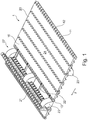
- FIG 1 is illustrated a section of a conveyor belt 1 made of modular belt modules where a first type of modular belt modules 10 are of a standard well-known type.
- the modular belt modules 10 are provided with eye-parts 11 spaced by apertures 12.
- the eye-parts 11 are provided with lateral apertures such that by arranging the eye-parts 11 of an adjacent belt module in the apertures 12, the apertures of the eye-parts will overlap, and it is possible to connect adjacent modular belt links by inserting a connection pin 13 through the overlapping apertures in the eye-parts and in this manner create a pivotable connection between adjacent belt modules.
- This second type of module 20 has an upper part 21 and a lower part 22.
- the upper 21 and lower 22 parts of the belt modules 20 are pivotally connected such that the upper part 21 of the belt module 20 may be arranged in the same surface plane as the regular modules 10 and in this manner constitute a substantially flat and flush conveyor belt surface. Due to the pivot arrangement of the upper part relative to the lower part the upper part may also be brought into a position where the surface of the upper part is elevated to any angle relative to the surface of the conveyor belt, but most preferred at an angle of approximately 90° as illustrated with the module 20'.
- the inventive module 20 has as already explained above an upper part 21 and a lower part 22.
- the size of the lower part 22 is such that the modular sectioning of the conveyor belt is the same as the regular modular belt modules 10 and therefore the inclusion of the two part belt modules in a regular conveyor belt does not give rise to any modification etc.
- the lower module part 22 is in the shape of connectors which will be further explained with reference to figure 5 .
- the upper part 21 of the module 20 is provided with means 23 in the shape of notches where the notches 23 project below the lower part when the upper part is in contact with the lower part as illustrated with the module 20.
- In the conveyor structure (not illustrated) is provided rails which engage the notches 23 urging the notches upwards.
- the engagement of the notches will cause the upper part 21 to pivot as illustrated in the left side of figure 1 .
- Due to the configuration of the notches 23 as illustrated in the embodiment in figure 1 the upper part 21 of the modular belt module 20 will now act as a product support or a flight as the conveyor structure belt 1 travels in the direction indicated by the arrow 2.
- connection members 22 share the space between two eye parts with the hinge part 25 of the upper modular member.
- connection bridges 22 Although the lower part of the module 20 in the depicted embodiment is in the shape of connection bridges 22 it will be clear that also plate shape members may be used.
- connection bridges 22 are the possibility to clean the conveyor belt, for example during the return run when it is mounted in a conveyor structure. Especially for applications in the food industry it is very important to retain a very high hygienic standard and by being able to access both the underside and the top side of the pivoting modular belt module a thorough cleaning may be attained.
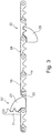
- FIG 3 is illustrated a side view of a conveyor belt incorporating two modular belt modules according to the present invention.
- the right hand module 20 is in a position where the upper surface of the upper part 21 is substantially flush with the transport surface 24 of the conveyor belt. In this position the notch 23 is not activated by an activating rail arranged underneath the conveyor belt as a part of the conveying structure.
- the modular belt module 20' illustrated in the left hand part of the figure is, however, activated by an activating rail which is substantially flush with the underside of the conveyor belt thereby forcing the upper part 21 of the modular belt module to pivot into the depicted position where the upper part 21 has the function of a product support or flight.
- the notch 23 extends below the lower part of the module 22 and may due to the hinge arrangement created by the pin 13 pivot into a position where the notch is substantially flush with the underside of the modular belt module and the conveyor belt structure as such.
- FIG 4 is illustrated a view comparable to figure 2 , but in this embodiment the modular belt module according to the invention has a width which is smaller than the regular belt modules 10 leaving an open space 26.
- This space 26 is created in order to allow the conveyor belt to have an upper guide member (not illustrated) such that the conveyor belt may be maintained in a firm position in the conveyor structure by an upper and lower guide member and still allow the inventive modular belt module 20 according to the present invention to pivot regardless of the limitations of the upper guide rail. Therefore the space 26 shall correspond to the width of an upper guide rail in order to allow the modular belt module 20 to pivot as explained above.
- connection bridge 22 shares a space between two adjacent eye-parts of an adjacent belt link 10' and as such the modular belt module according to the present invention is fully integrated in a normal conveyor belt structure without special adaptations. This is important in that it will be possible to create a conveyor structure using regular/normal sprocket wheels and where only one sprocket wheel is driven such that problems with synchronisation of for example more driven sprocket members is avoided.
- the invention is directed to a two part modular belt module which is fully integrable in a conventional conveyor belt structure made up of modular belt modules and by simply arranging activating rails in the conveyor structure, the modular belt module according to the invention may be activated such that the upper part of the belt module will function as a product support/flight.
- conveyor belts are usable in many aspects of industry and also for horizontal conveyors it may be advantageous to be able to control when the product support is activated such that for example cardboard boxes or other larger items may be slid onto the conveyor belt and after the conveyor belt's loading station the product support may be activated in order to push the cardboard box or large item along the conveyor belt path.
Landscapes
- Engineering & Computer Science (AREA)
- Mechanical Engineering (AREA)
- Chain Conveyers (AREA)
Claims (7)
- Modulares Bandmodul des Typs mit einer Breite und einer Länge, wobei die Breite und Länge eine Ebene und eine Dicke orthogonal zu der Ebene definieren, so dass das Modul durch zwei Längsseiten und eine Vorder- und Rückseite begrenzt ist, wobei das Modul einen oberen Teil (21) und einen unteren Teil (22) umfasst, wobei sowohl der obere als auch der untere Teil (21, 22) im Gebrauch mit einem nach vorne angeordneten Bandmodul schwenkbar verbindbar sind, wohingegen nur der untere Teil (22) im Gebrauch mit einem nach hinten angeordneten Bandmodul verbunden ist, und wobei der obere Teil (21), wenn es in Kontakt mit dem unteren Teil (22) steht, mit Mitteln (23) versehen ist, die unter dem unteren Teil (22) hervorstehen, und wobei das Modul mit beabstandeten Ösenteilen (11) entlang der Vorder- und Rückseiten versehen ist, so dass Ösenteile entlang einer Vorderseite zwischen Ösenteile entlang einer Rückseite eingreifen können, und wobei der untere Teil (22) aus zwei oder mehr lateral angeordneten Verbindungsbrücken besteht, dadurch gekennzeichnet, dass die an dem oberen Teil (21) angeordneten Mittel (23), die unter dem unteren Teil (22) hervorstehen, eine Erstreckung aufweisen, die es dem oberen Teil (21) ermöglicht, aus der Ebene des Förderers zu schwenken bis zu einem Winkel von ungefähr 90 Grad relativ zur Fördereroberfläche (24), wenn die Mittel (23) bündig mit der Unterseite des Unterteils (22) gebracht werden.
- Modulares Bandmodul nach Anspruch 1, wobei jede Brücke (22) eine Breite hat, die dem Raum (12) zwischen zwei Ösenteilen (11) entspricht.
- Modulares Bandmodul nach Anspruch 1 oder 2, wobei die Länge des oberen Teils (21) in der beabsichtigten Bewegungsrichtung größer ist als die Länge des unteren Teils (22).
- Förderstruktur, umfassend eine Unterstruktur, die die Strecke eines endlosen Förderbands definiert, wobei Kettenräder an jedem Ende der Strecke angeordnet sind, wobei mindestens ein Kettenrad mit Antriebsmitteln versehen ist, um das Förderband entlang der Strecke anzutreiben, wodurch ein oberer Vorlauf und ein unterer Rücklauf definiert werden, und wobei das Förderband aus mindestens zwei Typen eines modularen Bandmoduls besteht:- ein erster Typ nach einem der Ansprüche 1 bis 3 mit einer Breite und einer Länge, wobei die Breite und Länge eine Ebene und eine Dicke orthogonal zu der Ebene definieren, so dass das Modul durch zwei Längsseiten und eine Vorder- und Rückseite begrenzt ist, wobei das Modul einen oberen Teil (21) und einen unteren Teil (22) umfasst, wobei sowohl der obere als auch der untere Teil (21, 22) im Gebrauch mit einem nach vorne angeordneten Bandmodul schwenkbar verbindbar sind, wohingegen nur der untere Teil (22) im Gebrauch mit einem nach hinten angeordneten Bandmodul verbunden ist, und wobei der obere Teil (21), wenn er in Kontakt mit dem unteren Teil (22) steht, mit Mitteln (23) versehen ist, die unter dem unteren Teil (22) hervorstehen,
und- einem zweiten Typ eines modularen Bandmoduls, das Mittel zum Verbinden mit benachbarten Bandmodulen entlang gegenüberliegender Seiten aufweist, wobei die Mittel auch zum Verbinden mit dem ersten Modultyp geeignet sind,wobei die Förderstruktur ferner eine oder mehrere Aktivierungsschienen aufweist, die unter der Förderbandstecke an Positionen angeordnet sind, an denen es erwünscht ist, in die Mittel (23), die unter dem unteren Teil (22) des ersten Modultyps hervorstehen, einzugreifen, und dadurch den oberen Teil (21) des ersten Moduls aus der Oberflächenebene des Förderbandes zu schwenken. - Förderstruktur nach Anspruch 5, wobei die Strecke durch einen ersten im Wesentlichen horizontalen Abschnitt definiert ist, der mit einem geneigten Abschnitt verbunden ist, der seinerseits mit einem zweiten im Wesentlichen horizontalen Abschnitt verbunden ist, wobei der zweite horizontale Abschnitt relativ zu dem ersten im Wesentlichen horizontalen Abschnitt erhöht ist.
- Förderband, das aus mindestens zwei Typen von modularen Bandmodulen aufgebaut ist, wobei beide Typen Mittel zum schwenkbaren Verbinden mit benachbarten Bandmodulen umfassen, wobei ein erster Typ von modularen Bandmodulen nach Anspruch 1 bis 6 definiert ist, und ein zweites modulares Bandmodul zwei gegenüberliegende Seitenflächen umfasst, wobei jede Seite Mittel zum schwenkbaren Verbinden mit benachbarten Modulbandmodulen des ersten oder zweiten Typs aufweist.
- Förderband nach Anspruch 6, wobei die modularen Bandmodule in Reihen angeordnet sind, und wobei in den Reihen, die aus einem oder mehreren Modulen des ersten Typs bestehen, die Breite der Reihe geringer ist als die Reihen, die aus anderen modularen Bandmodulen bestehen.
Applications Claiming Priority (2)
| Application Number | Priority Date | Filing Date | Title |
|---|---|---|---|
| DKPA201370021 | 2013-01-15 | ||
| PCT/DK2014/050006 WO2014111091A1 (en) | 2013-01-15 | 2014-01-13 | Pivot link |
Publications (2)
| Publication Number | Publication Date |
|---|---|
| EP2945888A1 EP2945888A1 (de) | 2015-11-25 |
| EP2945888B1 true EP2945888B1 (de) | 2018-03-21 |
Family
ID=49955799
Family Applications (1)
| Application Number | Title | Priority Date | Filing Date |
|---|---|---|---|
| EP14700325.5A Active EP2945888B1 (de) | 2013-01-15 | 2014-01-13 | Gelenkverbindung |
Country Status (5)
| Country | Link |
|---|---|
| US (1) | US9676556B2 (de) |
| EP (1) | EP2945888B1 (de) |
| DK (1) | DK2945888T3 (de) |
| ES (1) | ES2674488T3 (de) |
| WO (1) | WO2014111091A1 (de) |
Families Citing this family (10)
| Publication number | Priority date | Publication date | Assignee | Title |
|---|---|---|---|---|
| USD916415S1 (en) * | 2012-01-12 | 2021-04-13 | MoveRoll Oy | Paper roll conveyor module |
| US10723556B1 (en) * | 2019-05-09 | 2020-07-28 | Arnold Jäger Holding GmbH | Pick-up web for an agricultural machine, in particular, a nut harvester |
| USD924529S1 (en) * | 2020-03-09 | 2021-07-06 | Habasit Ag | Conveyor belt slat |
| USD924531S1 (en) * | 2020-03-12 | 2021-07-06 | Habasit Ag | Conveyor belt slat |
| USD934525S1 (en) * | 2020-03-12 | 2021-10-26 | Habasit Ag | Conveyor belt slat |
| USD924530S1 (en) * | 2020-03-12 | 2021-07-06 | Habasit Ag | Conveyor belt slat |
| USD934526S1 (en) * | 2020-03-12 | 2021-10-26 | Habasit Ag | Conveyor belt slat |
| BE1028434B1 (nl) | 2020-06-25 | 2022-01-31 | Marelec Construct Nv | Transportsysteem met opklapbare meenemers |
| US11807473B2 (en) | 2020-07-09 | 2023-11-07 | Laitram, L.L.C. | Apparatus and methods for dynamically controlling the spacing of conveyed objects |
| CN112640948B (zh) * | 2020-12-21 | 2022-05-24 | 湛江市粤水渔业有限公司 | 一种水产品加工装置 |
Family Cites Families (4)
| Publication number | Priority date | Publication date | Assignee | Title |
|---|---|---|---|---|
| NL1011264C1 (nl) * | 1998-03-20 | 1999-09-24 | Ammeraal International B V | Transportsysteem voor het transporteren en accumuleren van voorwerpen. |
| US7134545B1 (en) * | 2006-02-16 | 2006-11-14 | Chris Smith | Conveyor apparatus and system |
| JP5345623B2 (ja) | 2007-08-22 | 2013-11-20 | レイトラム リミテッド ライアビリティー カンパニー | 荷物間に間隔を設けるコンベヤと方法 |
| AU2011205567B2 (en) | 2010-01-13 | 2013-11-21 | Laitram, L.L.C. | Reverse meter belt conveyor |
-
2014
- 2014-01-13 WO PCT/DK2014/050006 patent/WO2014111091A1/en not_active Ceased
- 2014-01-13 ES ES14700325.5T patent/ES2674488T3/es active Active
- 2014-01-13 US US14/760,919 patent/US9676556B2/en active Active
- 2014-01-13 EP EP14700325.5A patent/EP2945888B1/de active Active
- 2014-01-13 DK DK14700325.5T patent/DK2945888T3/en active
Also Published As
| Publication number | Publication date |
|---|---|
| EP2945888A1 (de) | 2015-11-25 |
| ES2674488T3 (es) | 2018-07-02 |
| DK2945888T3 (en) | 2018-06-18 |
| US20150344228A1 (en) | 2015-12-03 |
| WO2014111091A1 (en) | 2014-07-24 |
| US9676556B2 (en) | 2017-06-13 |
Similar Documents
| Publication | Publication Date | Title |
|---|---|---|
| EP2945888B1 (de) | Gelenkverbindung | |
| CA2592580C (en) | Conveyor having a conveyor belt with flights, including segmented flights for gapless end transfer | |
| EP1687221B1 (de) | Kunststoffförderbandmodule mit seitenschutz | |
| EP2877413B1 (de) | Modulares förderband mit erweiterten erhöhten rippen | |
| EP3114058B1 (de) | Übertragungsvorrichtung, fördersystem mit einer übertragungsvorrichtung und verfahren zur übertragung von geförderten produkten | |
| EP1826159A1 (de) | Fördersystem | |
| US4627530A (en) | Elevating chain conveyor | |
| CA2656246C (en) | Modular conveyor belt with cam flights | |
| JP3616624B2 (ja) | コンベヤチェーン | |
| EP0142726B1 (de) | Hebe-Kettenförderer | |
| EP2945889B1 (de) | Zufuhr für einen produktunterstützungsförderer | |
| EP1546011B1 (de) | Fördersystem mit einer überschiebvorrichtung zwischen zwei bandförderern und verwendung eines zwischenelementes | |
| EP1890950B1 (de) | Kunststoffförderbänder und module mit seitenkanälen | |
| WO2017023488A1 (en) | Conveyor belt and modules with flights at the hinge | |
| US20090050449A1 (en) | Conveying system | |
| GB2515775A (en) | Conveyor and conveyor structure | |
| EP3652091B1 (de) | Bandförderer und modulares förderband für schrägen | |
| EP4172076B1 (de) | Fördersystem mit klappträgern |
Legal Events
| Date | Code | Title | Description |
|---|---|---|---|
| PUAI | Public reference made under article 153(3) epc to a published international application that has entered the european phase |
Free format text: ORIGINAL CODE: 0009012 |
|
| 17P | Request for examination filed |
Effective date: 20150814 |
|
| AK | Designated contracting states |
Kind code of ref document: A1 Designated state(s): AL AT BE BG CH CY CZ DE DK EE ES FI FR GB GR HR HU IE IS IT LI LT LU LV MC MK MT NL NO PL PT RO RS SE SI SK SM TR |
|
| AX | Request for extension of the european patent |
Extension state: BA ME |
|
| DAX | Request for extension of the european patent (deleted) | ||
| STAA | Information on the status of an ep patent application or granted ep patent |
Free format text: STATUS: EXAMINATION IS IN PROGRESS |
|
| 17Q | First examination report despatched |
Effective date: 20161024 |
|
| GRAP | Despatch of communication of intention to grant a patent |
Free format text: ORIGINAL CODE: EPIDOSNIGR1 |
|
| STAA | Information on the status of an ep patent application or granted ep patent |
Free format text: STATUS: GRANT OF PATENT IS INTENDED |
|
| INTG | Intention to grant announced |
Effective date: 20170727 |
|
| GRAJ | Information related to disapproval of communication of intention to grant by the applicant or resumption of examination proceedings by the epo deleted |
Free format text: ORIGINAL CODE: EPIDOSDIGR1 |
|
| STAA | Information on the status of an ep patent application or granted ep patent |
Free format text: STATUS: EXAMINATION IS IN PROGRESS |
|
| GRAP | Despatch of communication of intention to grant a patent |
Free format text: ORIGINAL CODE: EPIDOSNIGR1 |
|
| STAA | Information on the status of an ep patent application or granted ep patent |
Free format text: STATUS: GRANT OF PATENT IS INTENDED |
|
| INTC | Intention to grant announced (deleted) | ||
| INTG | Intention to grant announced |
Effective date: 20171011 |
|
| GRAS | Grant fee paid |
Free format text: ORIGINAL CODE: EPIDOSNIGR3 |
|
| GRAA | (expected) grant |
Free format text: ORIGINAL CODE: 0009210 |
|
| STAA | Information on the status of an ep patent application or granted ep patent |
Free format text: STATUS: THE PATENT HAS BEEN GRANTED |
|
| AK | Designated contracting states |
Kind code of ref document: B1 Designated state(s): AL AT BE BG CH CY CZ DE DK EE ES FI FR GB GR HR HU IE IS IT LI LT LU LV MC MK MT NL NO PL PT RO RS SE SI SK SM TR |
|
| REG | Reference to a national code |
Ref country code: GB Ref legal event code: FG4D |
|
| REG | Reference to a national code |
Ref country code: CH Ref legal event code: EP |
|
| REG | Reference to a national code |
Ref country code: AT Ref legal event code: REF Ref document number: 980840 Country of ref document: AT Kind code of ref document: T Effective date: 20180415 |
|
| REG | Reference to a national code |
Ref country code: IE Ref legal event code: FG4D |
|
| REG | Reference to a national code |
Ref country code: DE Ref legal event code: R096 Ref document number: 602014022570 Country of ref document: DE |
|
| REG | Reference to a national code |
Ref country code: DK Ref legal event code: T3 Effective date: 20180614 |
|
| REG | Reference to a national code |
Ref country code: ES Ref legal event code: FG2A Ref document number: 2674488 Country of ref document: ES Kind code of ref document: T3 Effective date: 20180702 |
|
| REG | Reference to a national code |
Ref country code: NL Ref legal event code: FP |
|
| REG | Reference to a national code |
Ref country code: SE Ref legal event code: TRGR |
|
| PG25 | Lapsed in a contracting state [announced via postgrant information from national office to epo] |
Ref country code: CY Free format text: LAPSE BECAUSE OF FAILURE TO SUBMIT A TRANSLATION OF THE DESCRIPTION OR TO PAY THE FEE WITHIN THE PRESCRIBED TIME-LIMIT Effective date: 20180321 Ref country code: LT Free format text: LAPSE BECAUSE OF FAILURE TO SUBMIT A TRANSLATION OF THE DESCRIPTION OR TO PAY THE FEE WITHIN THE PRESCRIBED TIME-LIMIT Effective date: 20180321 Ref country code: HR Free format text: LAPSE BECAUSE OF FAILURE TO SUBMIT A TRANSLATION OF THE DESCRIPTION OR TO PAY THE FEE WITHIN THE PRESCRIBED TIME-LIMIT Effective date: 20180321 Ref country code: FI Free format text: LAPSE BECAUSE OF FAILURE TO SUBMIT A TRANSLATION OF THE DESCRIPTION OR TO PAY THE FEE WITHIN THE PRESCRIBED TIME-LIMIT Effective date: 20180321 |
|
| REG | Reference to a national code |
Ref country code: LT Ref legal event code: MG4D |
|
| REG | Reference to a national code |
Ref country code: AT Ref legal event code: MK05 Ref document number: 980840 Country of ref document: AT Kind code of ref document: T Effective date: 20180321 |
|
| REG | Reference to a national code |
Ref country code: NO Ref legal event code: T2 Effective date: 20180321 |
|
| PG25 | Lapsed in a contracting state [announced via postgrant information from national office to epo] |
Ref country code: BG Free format text: LAPSE BECAUSE OF FAILURE TO SUBMIT A TRANSLATION OF THE DESCRIPTION OR TO PAY THE FEE WITHIN THE PRESCRIBED TIME-LIMIT Effective date: 20180621 Ref country code: GR Free format text: LAPSE BECAUSE OF FAILURE TO SUBMIT A TRANSLATION OF THE DESCRIPTION OR TO PAY THE FEE WITHIN THE PRESCRIBED TIME-LIMIT Effective date: 20180622 Ref country code: LV Free format text: LAPSE BECAUSE OF FAILURE TO SUBMIT A TRANSLATION OF THE DESCRIPTION OR TO PAY THE FEE WITHIN THE PRESCRIBED TIME-LIMIT Effective date: 20180321 Ref country code: RS Free format text: LAPSE BECAUSE OF FAILURE TO SUBMIT A TRANSLATION OF THE DESCRIPTION OR TO PAY THE FEE WITHIN THE PRESCRIBED TIME-LIMIT Effective date: 20180321 |
|
| PG25 | Lapsed in a contracting state [announced via postgrant information from national office to epo] |
Ref country code: EE Free format text: LAPSE BECAUSE OF FAILURE TO SUBMIT A TRANSLATION OF THE DESCRIPTION OR TO PAY THE FEE WITHIN THE PRESCRIBED TIME-LIMIT Effective date: 20180321 Ref country code: PL Free format text: LAPSE BECAUSE OF FAILURE TO SUBMIT A TRANSLATION OF THE DESCRIPTION OR TO PAY THE FEE WITHIN THE PRESCRIBED TIME-LIMIT Effective date: 20180321 Ref country code: RO Free format text: LAPSE BECAUSE OF FAILURE TO SUBMIT A TRANSLATION OF THE DESCRIPTION OR TO PAY THE FEE WITHIN THE PRESCRIBED TIME-LIMIT Effective date: 20180321 Ref country code: AL Free format text: LAPSE BECAUSE OF FAILURE TO SUBMIT A TRANSLATION OF THE DESCRIPTION OR TO PAY THE FEE WITHIN THE PRESCRIBED TIME-LIMIT Effective date: 20180321 |
|
| PG25 | Lapsed in a contracting state [announced via postgrant information from national office to epo] |
Ref country code: SM Free format text: LAPSE BECAUSE OF FAILURE TO SUBMIT A TRANSLATION OF THE DESCRIPTION OR TO PAY THE FEE WITHIN THE PRESCRIBED TIME-LIMIT Effective date: 20180321 Ref country code: AT Free format text: LAPSE BECAUSE OF FAILURE TO SUBMIT A TRANSLATION OF THE DESCRIPTION OR TO PAY THE FEE WITHIN THE PRESCRIBED TIME-LIMIT Effective date: 20180321 Ref country code: SK Free format text: LAPSE BECAUSE OF FAILURE TO SUBMIT A TRANSLATION OF THE DESCRIPTION OR TO PAY THE FEE WITHIN THE PRESCRIBED TIME-LIMIT Effective date: 20180321 |
|
| PG25 | Lapsed in a contracting state [announced via postgrant information from national office to epo] |
Ref country code: PT Free format text: LAPSE BECAUSE OF FAILURE TO SUBMIT A TRANSLATION OF THE DESCRIPTION OR TO PAY THE FEE WITHIN THE PRESCRIBED TIME-LIMIT Effective date: 20180723 |
|
| REG | Reference to a national code |
Ref country code: DE Ref legal event code: R097 Ref document number: 602014022570 Country of ref document: DE |
|
| PLBE | No opposition filed within time limit |
Free format text: ORIGINAL CODE: 0009261 |
|
| STAA | Information on the status of an ep patent application or granted ep patent |
Free format text: STATUS: NO OPPOSITION FILED WITHIN TIME LIMIT |
|
| 26N | No opposition filed |
Effective date: 20190102 |
|
| PG25 | Lapsed in a contracting state [announced via postgrant information from national office to epo] |
Ref country code: SI Free format text: LAPSE BECAUSE OF FAILURE TO SUBMIT A TRANSLATION OF THE DESCRIPTION OR TO PAY THE FEE WITHIN THE PRESCRIBED TIME-LIMIT Effective date: 20180321 |
|
| PG25 | Lapsed in a contracting state [announced via postgrant information from national office to epo] |
Ref country code: MC Free format text: LAPSE BECAUSE OF FAILURE TO SUBMIT A TRANSLATION OF THE DESCRIPTION OR TO PAY THE FEE WITHIN THE PRESCRIBED TIME-LIMIT Effective date: 20180321 |
|
| PG25 | Lapsed in a contracting state [announced via postgrant information from national office to epo] |
Ref country code: LU Free format text: LAPSE BECAUSE OF NON-PAYMENT OF DUE FEES Effective date: 20190113 |
|
| REG | Reference to a national code |
Ref country code: BE Ref legal event code: MM Effective date: 20190131 |
|
| REG | Reference to a national code |
Ref country code: IE Ref legal event code: MM4A |
|
| PG25 | Lapsed in a contracting state [announced via postgrant information from national office to epo] |
Ref country code: BE Free format text: LAPSE BECAUSE OF NON-PAYMENT OF DUE FEES Effective date: 20190131 |
|
| PG25 | Lapsed in a contracting state [announced via postgrant information from national office to epo] |
Ref country code: IE Free format text: LAPSE BECAUSE OF NON-PAYMENT OF DUE FEES Effective date: 20190113 |
|
| PG25 | Lapsed in a contracting state [announced via postgrant information from national office to epo] |
Ref country code: TR Free format text: LAPSE BECAUSE OF FAILURE TO SUBMIT A TRANSLATION OF THE DESCRIPTION OR TO PAY THE FEE WITHIN THE PRESCRIBED TIME-LIMIT Effective date: 20180321 |
|
| PG25 | Lapsed in a contracting state [announced via postgrant information from national office to epo] |
Ref country code: MT Free format text: LAPSE BECAUSE OF NON-PAYMENT OF DUE FEES Effective date: 20190113 |
|
| PG25 | Lapsed in a contracting state [announced via postgrant information from national office to epo] |
Ref country code: HU Free format text: LAPSE BECAUSE OF FAILURE TO SUBMIT A TRANSLATION OF THE DESCRIPTION OR TO PAY THE FEE WITHIN THE PRESCRIBED TIME-LIMIT; INVALID AB INITIO Effective date: 20140113 |
|
| PG25 | Lapsed in a contracting state [announced via postgrant information from national office to epo] |
Ref country code: MK Free format text: LAPSE BECAUSE OF FAILURE TO SUBMIT A TRANSLATION OF THE DESCRIPTION OR TO PAY THE FEE WITHIN THE PRESCRIBED TIME-LIMIT Effective date: 20180321 |
|
| P01 | Opt-out of the competence of the unified patent court (upc) registered |
Effective date: 20230516 |
|
| PGFP | Annual fee paid to national office [announced via postgrant information from national office to epo] |
Ref country code: CH Payment date: 20250201 Year of fee payment: 12 |
|
| PGFP | Annual fee paid to national office [announced via postgrant information from national office to epo] |
Ref country code: CZ Payment date: 20251219 Year of fee payment: 13 |
|
| REG | Reference to a national code |
Ref country code: CH Ref legal event code: U11 Free format text: ST27 STATUS EVENT CODE: U-0-0-U10-U11 (AS PROVIDED BY THE NATIONAL OFFICE) Effective date: 20260201 |
|
| PGFP | Annual fee paid to national office [announced via postgrant information from national office to epo] |
Ref country code: NL Payment date: 20260126 Year of fee payment: 13 |
|
| PGFP | Annual fee paid to national office [announced via postgrant information from national office to epo] |
Ref country code: SE Payment date: 20260127 Year of fee payment: 13 |
|
| PGFP | Annual fee paid to national office [announced via postgrant information from national office to epo] |
Ref country code: GB Payment date: 20260127 Year of fee payment: 13 |
|
| PGFP | Annual fee paid to national office [announced via postgrant information from national office to epo] |
Ref country code: ES Payment date: 20260202 Year of fee payment: 13 |
|
| PGFP | Annual fee paid to national office [announced via postgrant information from national office to epo] |
Ref country code: NO Payment date: 20260128 Year of fee payment: 13 Ref country code: DE Payment date: 20260128 Year of fee payment: 13 Ref country code: DK Payment date: 20260126 Year of fee payment: 13 |
|
| PGFP | Annual fee paid to national office [announced via postgrant information from national office to epo] |
Ref country code: IT Payment date: 20260121 Year of fee payment: 13 |
|
| PGFP | Annual fee paid to national office [announced via postgrant information from national office to epo] |
Ref country code: IS Payment date: 20260113 Year of fee payment: 13 Ref country code: FR Payment date: 20260126 Year of fee payment: 13 |