EP2946145B1 - Gekühlte abkühlzonenanordnung einer brennkammer - Google Patents
Gekühlte abkühlzonenanordnung einer brennkammer Download PDFInfo
- Publication number
- EP2946145B1 EP2946145B1 EP13872043.8A EP13872043A EP2946145B1 EP 2946145 B1 EP2946145 B1 EP 2946145B1 EP 13872043 A EP13872043 A EP 13872043A EP 2946145 B1 EP2946145 B1 EP 2946145B1
- Authority
- EP
- European Patent Office
- Prior art keywords
- grommet
- combustor
- shell
- liner
- cooling
- Prior art date
- Legal status (The legal status is an assumption and is not a legal conclusion. Google has not performed a legal analysis and makes no representation as to the accuracy of the status listed.)
- Active
Links
Images



Classifications
-
- F—MECHANICAL ENGINEERING; LIGHTING; HEATING; WEAPONS; BLASTING
- F23—COMBUSTION APPARATUS; COMBUSTION PROCESSES
- F23R—GENERATING COMBUSTION PRODUCTS OF HIGH PRESSURE OR HIGH VELOCITY, e.g. GAS-TURBINE COMBUSTION CHAMBERS
- F23R3/00—Continuous combustion chambers using liquid or gaseous fuel
- F23R3/005—Combined with pressure or heat exchangers
-
- F—MECHANICAL ENGINEERING; LIGHTING; HEATING; WEAPONS; BLASTING
- F02—COMBUSTION ENGINES; HOT-GAS OR COMBUSTION-PRODUCT ENGINE PLANTS
- F02C—GAS-TURBINE PLANTS; AIR INTAKES FOR JET-PROPULSION PLANTS; CONTROLLING FUEL SUPPLY IN AIR-BREATHING JET-PROPULSION PLANTS
- F02C7/00—Features, components parts, details or accessories, not provided for in, or of interest apart form groups F02C1/00 - F02C6/00; Air intakes for jet-propulsion plants
- F02C7/12—Cooling of plants
- F02C7/16—Cooling of plants characterised by cooling medium
- F02C7/18—Cooling of plants characterised by cooling medium the medium being gaseous, e.g. air
-
- F—MECHANICAL ENGINEERING; LIGHTING; HEATING; WEAPONS; BLASTING
- F23—COMBUSTION APPARATUS; COMBUSTION PROCESSES
- F23R—GENERATING COMBUSTION PRODUCTS OF HIGH PRESSURE OR HIGH VELOCITY, e.g. GAS-TURBINE COMBUSTION CHAMBERS
- F23R3/00—Continuous combustion chambers using liquid or gaseous fuel
- F23R3/02—Continuous combustion chambers using liquid or gaseous fuel characterised by the air-flow or gas-flow configuration
- F23R3/04—Air inlet arrangements
- F23R3/06—Arrangement of apertures along the flame tube
-
- F—MECHANICAL ENGINEERING; LIGHTING; HEATING; WEAPONS; BLASTING
- F23—COMBUSTION APPARATUS; COMBUSTION PROCESSES
- F23R—GENERATING COMBUSTION PRODUCTS OF HIGH PRESSURE OR HIGH VELOCITY, e.g. GAS-TURBINE COMBUSTION CHAMBERS
- F23R2900/00—Special features of, or arrangements for continuous combustion chambers; Combustion processes therefor
- F23R2900/03041—Effusion cooled combustion chamber walls or domes
-
- F—MECHANICAL ENGINEERING; LIGHTING; HEATING; WEAPONS; BLASTING
- F23—COMBUSTION APPARATUS; COMBUSTION PROCESSES
- F23R—GENERATING COMBUSTION PRODUCTS OF HIGH PRESSURE OR HIGH VELOCITY, e.g. GAS-TURBINE COMBUSTION CHAMBERS
- F23R2900/00—Special features of, or arrangements for continuous combustion chambers; Combustion processes therefor
- F23R2900/03042—Film cooled combustion chamber walls or domes
-
- F—MECHANICAL ENGINEERING; LIGHTING; HEATING; WEAPONS; BLASTING
- F23—COMBUSTION APPARATUS; COMBUSTION PROCESSES
- F23R—GENERATING COMBUSTION PRODUCTS OF HIGH PRESSURE OR HIGH VELOCITY, e.g. GAS-TURBINE COMBUSTION CHAMBERS
- F23R2900/00—Special features of, or arrangements for continuous combustion chambers; Combustion processes therefor
- F23R2900/03044—Impingement cooled combustion chamber walls or subassemblies
-
- Y—GENERAL TAGGING OF NEW TECHNOLOGICAL DEVELOPMENTS; GENERAL TAGGING OF CROSS-SECTIONAL TECHNOLOGIES SPANNING OVER SEVERAL SECTIONS OF THE IPC; TECHNICAL SUBJECTS COVERED BY FORMER USPC CROSS-REFERENCE ART COLLECTIONS [XRACs] AND DIGESTS
- Y02—TECHNOLOGIES OR APPLICATIONS FOR MITIGATION OR ADAPTATION AGAINST CLIMATE CHANGE
- Y02T—CLIMATE CHANGE MITIGATION TECHNOLOGIES RELATED TO TRANSPORTATION
- Y02T50/00—Aeronautics or air transport
- Y02T50/60—Efficient propulsion technologies, e.g. for aircraft
Definitions
- the present disclosure generally relates to gas turbine engines and, more specifically, to cooling of combustors in gas turbine engines.
- a gas turbine engine typically used as a source of propulsion in aircraft, operates by drawing in ambient air, combusting that air with a fuel, and then forcing the exhaust from the combustion process out of the engine.
- a fan on a forward end of the engine rotates to draw in ambient air.
- the air is then compressed by a compressor section having a low-pressure and high-pressure compressor. A portion of the compressed air is used to cool the combustor, while the rest is mixed with a fuel and ignited.
- an igniter generates an electrical spark to ignite the air-fuel mixture.
- the products of the combustion, water, CO 2 , NOx, and CO then travel out of the combustor and exhaust through a turbine.
- the turbine section also having a low-pressure and high-pressure turbine, is forced to rotate as the exhaust exits the engine.
- the turbine section and the compressor section are connected by two concentrically mounted rotating shafts running through the center of the engine. One shaft connects the low-pressure compressor and turbine, while the other shaft connects the high-pressure compressor and turbine.
- Combustors for gas turbine engines typically have an outer combustor shell and an outer liner, which may be made of a plurality of panels, disposed radially inside the outer combustor shell. Additionally, annular combustors have an inner shell and an inner liner radially outside of the inner shell. The inner and outer liners are separated by and define an annular combustion chamber. Flow cavities are typically provided between each pair of shells and liners. Cooling air is forced through these flow cavities and into the combustion chamber, creating a cooling film on hot surfaces of the liners.
- the remaining portion of the compressed air is used as dilution air to fully burn all of the fuel in the combustion chamber and reduce the temperature of the exhaust.
- This dilution air is typically injected into a rear section of the combustion chamber through a plurality of holes defined by a plurality of grommets.
- engines did not provide any extra cooling for such grommets, and indeed until recent improvements in the design of combustors, extra cooling was often not needed.
- the temperatures in the combustion chambers have increased. Advanced cooling for the combustor, including for the grommets, is therefore needed. If these areas are not adequately cooled, spallation of the liner, loss of combustor liner material, and cracks or other heat stress related fatigue may occur.
- GB2353589 describes a combustor according to the preamble of claim 1.
- a combustor according to claim 1 is defined.
- the cooling channel may be oriented perpendicular to a radially inward surface of the grommet with respect to an axis of the combustor extending longitudinally through the combustor.
- the cooling channel may be provided at a non-perpendicular angle to the radially inward surface of the grommet.
- the cooling channel may communicate through the grommet from a surrounding surface of the grommet oriented perpendicular to the shell of the combustor and facing away from the hole defined y the grommet to the radially inward surface of the grommet.
- the shell is engaged with a radially outward surface of the grommet with respect to the axis of the combustor.
- between six to sixteen cooling channels may communicate through the grommet.
- each cooling channel may be separated by a distance about equal to three to ten times the diameter of the cooling channels.
- the grommet has a second outward surface with respect to the axis of the combustor engaged with the shell of the combustor.
- the grommet is separate from the shell and a liner of the combustor, the liner being positioned radially inside the shell with respect to the axis of the combustor, and the grommet being positioned between the shell and liner.
- the grommet has a radially inward surface and a radially outward surface with respect to an axis extending longitudinally through the combustor, and the cooling channel may extend from the radially outward surface of the grommet to the radially inward surface of the grommet.
- a method of cooling a liner of a combustor according to claim 5 is disclosed.
- a gas turbine engine 100 has a fan 101 and a compressor section 102 provided at a front end 106 of the engine 100.
- the compressor section 102 includes a low-pressure compressor 103 and a high-pressure compressor 105.
- the low-pressure compressor 103 is connected to a first shaft 108 and the high-pressure compressor 105 is connected to a second shaft 109.
- the second shaft 109 is concentrically mounted around the first shaft 108 and both shafts 108, 109 extend along and rotate around a central axis 110 extending longitudinally through the engine 20.
- the fan 101 and compressor section 102 rotate, the fan 101 draws ambient air 112 into the engine 100, and the compressor section 102 compresses the ambient air 110.
- the compressed air 114 may be forced through a diffuser 116 to a combustor 118. At the combustor 118, the compressed air 114 is split to be used in multiple ways.
- the combustor 118 has a shell 132 and may include a liner 130 mounted to the shell 132.
- the combustor 118 has an outer and inner set of shells and liners with respect to the central axis 110 that cooperate to define and are separated by an annular combustion chamber 135.
- a combustor axis 119 extends the longitudinally through the combustor 118 equidistant from the outer and inner shells 132.
- the shell 132 and associated liner 130 are separated by and define a flow cavity 170 therebetween.
- Some of the compressed air 114 may pass through a swirler 124 into the combustion chamber 135 as combustion air 122.
- the swirler 124 may create turbulence in the combustion air 122 which mixes the combustion air 122 and a fuel 126 entering the combustion chamber 135 by a fuel injector 128.
- the air-fuel mixture may then be ignited by an igniter 129 projecting through the liner 130 and shell 132 of the combustor 118.
- the combustion products may then be ejected from the combustion chamber 135 as exhaust 136.
- the exhaust 136 passes through a turbine section 138, having a high-pressure turbine 139 and a low pressure turbine 141, before exiting the engine 100.
- the high-pressure turbine 139 is also connected to the second shaft 109 and the low-pressure turbine 141 is connected to the first shaft 108 such that when the turbine section 138 is rotated by the kinetic energy of the exhaust 136, the shafts 108 and 109, and thus the compressor section 102, are rotated about the central axis 110. Thereby the process may draw in more ambient air 112 as the exhaust 136 exits the engine 20 and may be self-sustaining once it has begun.
- the compressed air 114 not entering through the swirlers 124 as combustion air 122 may be used as cooling air 144 and dilution air 146.
- the cooling air 144 flows through a plurality of impingement holes 172 communicating through the shell 132 into the flow cavity 170 and through a plurality of effusion holes 174 communicating through the liner 130 into the combustion chamber 135.
- the dilution air 146 may enter the combustion chamber 135 at a rear section 148 through at least one dilution hole 150 communicating through the liner 130 and shell 132.
- at least one dilution hole 150 communicates through the liner 130 and shell 132 in a forward section 152 of the combustion chamber 135.
- the dilution air 146 is burnt in the combustion chamber 135 to complete the combustion process. Additionally, the dilution air 146 may reduce the temperature of the exhaust 136 before the exhaust 136 reaches the turbine section 138.
- the liner 130 may be made up of a plurality of panels 154. Each of the panels 154 may have at least one dilution hole 150 defined by a generally cylindrical dilution hole grommet 156.
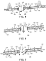
- the grommet 156 may be unitary with the liner 130 such as the raised platform illustrated in FIGS. 3 and 6-8 , or a separate element of the combustor 118 but in engagement with and positioned between the liner 130 and shell 132 of the combustor 118 as illustrated in FIGS. 2 , 4 and 5 .
- the grommet 156 is a separate element of the combustor engaged with and positioned between the shell 132 and liner 130 of the combustor 118.
- the grommet 156 has a radially outward surface 158 with respect to the combustor axis 119 and at least one cooling channel 160 communicating through the grommet 156 from the outward surface 158 to an opposing radially inward surface 159 of the grommet 156 still with respect to the combustor axis 119.
- the radially inward surface 159 may be flush with a hot surface 162 of the liner 130.
- the grommet 156 is unitary with the liner 130, such as illustrated in FIGS. 3 and 6-8 .
- the cooling channels 160 communicate through the grommet 156, or in these embodiments the raised platform that will herein after be referred to simply as the grommet 156, to the hot surface 162 of the liner 130.
- the inward surface 159 of a grommet 156 which is separate from the liner 130 is equivalent to the hot surface 162 of the liner 130 when the grommet 156 is unitary with the liner 130.
- each grommet 156 may be provided in the grommet 156 to provide various amounts of cooling air 144 to the radially inward surface 159 of the grommet 156 and/or the hot surface 162 of the liner 130.
- any number of cooling channels 160 may communicate through the grommet 156 to provide any desired amount of cooling air 144 to the radially inward surface 159 and/or hot surface 162.
- each of the cooling channels 160 are separated by a distance about equal to three to ten times the diameter 164 of the cooling channels 160 to provide an even distribution of the cooling air 144 on the radially inward surface 159 and/or hot surface 162.
- the cooling channels 160 may be separated by any desired distance to provide any desired distribution or concentration of cooling air 144 on the radially inward surface 159 and/or hot surface 162.
- the grommet 156 has a second radially outward surface 166 with respect to the combustor axis 119, which is engaged to an interior surface 167 of the shell 132 still with respect to the combustor axis 119, as seen in FIGS. 5-7 .
- Such engagement of the surfaces 166 and 167 prevent compressed air 114 from passing between the grommet 156 and shell 132 to enter the flow cavity 170.
- the first radially outward surface 158 of the grommet 156 may be flush with an exterior surface 168 of the shell 132 with respect to the combustor axis 119, as illustrated in FIGS. 5-7 , or may extend further radially outwards than the shell 132.
- the cooling channels 160 may be oriented at a non-perpendicular angle to the radially outward surface 158 of the grommet 156.
- the cooling channels 160 communicate from a generally cylindrical surrounding surface 178 of the grommet to the hot surface 162 of the liner 130.
- the surrounding surface 178 is oriented perpendicular to the radially outward surface 159 and faces away from the dilution hole 150 that is defined by the grommet 156.
- Such non-perpendicular cooling channels 160 may also be implemented in grommets 156 which are not unitary with the liner 130.
- the grommet 156 may only have a first radially outward surface 159 and not have a second radially outward surface 166.
- the first radially outward surface 159 is engaged with the shell 132 such that no compressed air 114 may flow between the shell 132 and the grommet 156.
- the cooling channels 160 of this embodiment communicate from the surrounding surface 178 of the grommet 156 to the hot surface 162 of the liner.
- the cooling channels 160 described above may also be implemented in grommets 156 that are not unitary with the liner 130.
- At least one dilution hole 150 may communicate through the shell 132 of the combustor 118 and be defined by the grommet 156 that, in this embodiment, is unitary with the shell 132.
- At least one cooling channel 160 communicates through the unitary grommet 156 and shell 132 to provide a path for cooling air 144 to flow into the combustion chamber 135.
- the cooling air 144 flowing through the cooling channels 160 described above and illustrated in FIGS. 2-9 cool the grommets 156, by transferring heat from the grommet 156 to the cooling air 144.
- the technology disclosed herein has industrial applicability in a variety of settings such as, but not limited to, cooling dilution hole grommets and the liner around dilution holes (or other holes) in combustors of gas turbine engines.
- Such engines may be used, for example, in aircraft to generate thrust or in land-based applications to generate power.
- This improvement over prior art reduces the temperature of the combustor liner around the dilution holes.
- the reduction in temperature makes the liner less susceptible to damage by heat during engine operations. Such damage may include spallation of the combustor liner, loss of combustor liner material, and cracks or other heat stress related fatigue in the combustor liner.
Landscapes
- Engineering & Computer Science (AREA)
- Chemical & Material Sciences (AREA)
- Combustion & Propulsion (AREA)
- Mechanical Engineering (AREA)
- General Engineering & Computer Science (AREA)
- Turbine Rotor Nozzle Sealing (AREA)
Claims (5)
- Brenner, der Folgendes umfasst:eine Hülle (132);eine Auskleidung (130), die an der Hülle (132) montiert ist und radial innerhalb der Hülle (132) in Bezug auf eine Achse (119) des Brenners positioniert ist, wobei die Hülle (132) und die Auskleidung (130) eine Brennerkammer (135) definieren;eine Durchführung (156), die eine radial innere und äußere Fläche (158, 159) aufweist, wobei die Durchführung (156) ein Verdünnungsloch (150) definiert, das durch die Hülle (132) und die Auskleidung (130) verläuft, wobei die Durchführung (156) an einer zweiten radial äußeren Fläche (166) in Eingriff mit der Auskleidung (130) und der Hülle (132) steht und dazwischen positioniert ist, sodass die zweite radial äußere Fläche (166) der Durchführung (156) in eine Innenfläche (167) der Hülle (132) eingreift; undeinen Kühlkanal (160), der durch die Durchführung (156) verläuft, dadurch gekennzeichnet, dass der Kühlkanal (160) durch die Durchführung (156) von der äußeren Fläche (158) zu der entgegengesetzten radial inneren Fläche (159) verläuft.
- Brenner nach Anspruch 1, wobei der Kühlkanal (160) senkrecht zu der radial inneren Fläche (159) der Durchführung (156) in Bezug auf die Achse (119) des Brenners ausgerichtet ist.
- Brenner nach Anspruch 1, wobei der Kühlkanal (160) in einem nicht senkrechten Winkel zu der radial innenliegenden Fläche (159) der Durchführung (156) bereitgestellt ist, und vorzugsweise durch die Durchführung (156) von einer umgebenden Fläche (178) der Durchführung (156) verläuft, die senkrecht zu der Hülle (132) des Brenners ausgerichtet ist und von dem Verdünnungsloch (150) abgewandt ist, das durch die Durchführung (156) zu der radial inneren Fläche (159) der Durchführung (156) definiert ist.
- Brenner nach einem der vorhergehenden Ansprüche, wobei zwischen sechs und sechzehn Kühlungskanäle (160) durch die Durchführung (156) verlaufen und wobei jeder Kühlkanal (160) vorzugsweise um eine Entfernung von etwa gleich drei zu zehn Mal den Durchmesser der Kühlkanäle (160) getrennt ist.
- Verfahren zum Kühlen einer Auskleidung eines Brenners, das Folgendes umfasst:Positionieren einer Durchführung (156) in Eingriff mit und zwischen einer Auskleidung (130) und einer Hülle (132) des Brenners, wobei die Durchführung (156) ein Verdünnungsloch (150) durch die Auskleidung (130) und die Hülle (132) definiert, wobei die Durchführung (156) eine radial innere und radial äußere Fläche (158, 159) und eine zweite radial äußere Fläche (166) zum Eingriff zwischen der Auskleidung und der Hülle aufweist, sodass die zweite radial äußere Fläche (166) der Durchführung (156) in eine Innenfläche (167) der Hülle (132) eingreift;Lenken von Kühlungsluft durch einen Kühlungskanal (160), der durch die Durchführung (156) verläuft, wobei der Kühlungskanal (160) durch die Durchführung (156) von der äußeren Fläche (158) zu einer entgegengesetzten radial inneren Fläche (159) verläuft; undKühlen der Durchführung (156) mit der Kühlungsluft, die durch den Kühlungskanal (160) strömt, durch Übertragen von Hitze von der Durchführung (156) an die Kühlungsluft;und vorzugsweise ferner das Blasen einer Flamme in dem Brenner von der inneren Fläche (159) der Durchführung (156) ab umfassend, wobei die Kühlungsluft durch den Kühlungskanal (160) strömt.
Applications Claiming Priority (1)
| Application Number | Priority Date | Filing Date | Title |
|---|---|---|---|
| PCT/US2013/021718 WO2014112992A1 (en) | 2013-01-16 | 2013-01-16 | Combustor cooled quench zone array |
Publications (3)
| Publication Number | Publication Date |
|---|---|
| EP2946145A1 EP2946145A1 (de) | 2015-11-25 |
| EP2946145A4 EP2946145A4 (de) | 2016-09-28 |
| EP2946145B1 true EP2946145B1 (de) | 2020-07-15 |
Family
ID=51209946
Family Applications (1)
| Application Number | Title | Priority Date | Filing Date |
|---|---|---|---|
| EP13872043.8A Active EP2946145B1 (de) | 2013-01-16 | 2013-01-16 | Gekühlte abkühlzonenanordnung einer brennkammer |
Country Status (3)
| Country | Link |
|---|---|
| US (2) | US20150354819A1 (de) |
| EP (1) | EP2946145B1 (de) |
| WO (1) | WO2014112992A1 (de) |
Families Citing this family (17)
| Publication number | Priority date | Publication date | Assignee | Title |
|---|---|---|---|---|
| US20150354819A1 (en) | 2013-01-16 | 2015-12-10 | United Technologies Corporation | Combustor Cooled Quench Zone Array |
| WO2015039075A1 (en) * | 2013-09-16 | 2015-03-19 | United Technologies Corporation | Angled combustor liner cooling holes through transverse structure within a gas turbine engine combustor |
| WO2015085065A1 (en) * | 2013-12-05 | 2015-06-11 | United Technologies Corporation | Cooling a quench aperture body of a combustor wall |
| US10533745B2 (en) * | 2014-02-03 | 2020-01-14 | United Technologies Corporation | Film cooling a combustor wall of a turbine engine |
| US10077903B2 (en) * | 2014-10-20 | 2018-09-18 | United Technologies Corporation | Hybrid through holes and angled holes for combustor grommet cooling |
| US20160178199A1 (en) * | 2014-12-17 | 2016-06-23 | United Technologies Corporation | Combustor dilution hole active heat transfer control apparatus and system |
| US9803863B2 (en) | 2015-05-13 | 2017-10-31 | Solar Turbines Incorporated | Controlled-leak combustor grommet |
| US10935243B2 (en) * | 2016-11-30 | 2021-03-02 | Raytheon Technologies Corporation | Regulated combustor liner panel for a gas turbine engine combustor |
| US10408453B2 (en) | 2017-07-19 | 2019-09-10 | United Technologies Corporation | Dilution holes for gas turbine engines |
| US11137140B2 (en) | 2017-10-04 | 2021-10-05 | Raytheon Technologies Corporation | Dilution holes with ridge feature for gas turbine engines |
| US11029027B2 (en) * | 2018-10-03 | 2021-06-08 | Raytheon Technologies Corporation | Dilution/effusion hole pattern for thick combustor panels |
| WO2022181694A1 (ja) * | 2021-02-25 | 2022-09-01 | 三菱パワー株式会社 | 燃焼器用筒、燃焼器、及びガスタービン |
| US11719438B2 (en) * | 2021-03-15 | 2023-08-08 | General Electric Company | Combustion liner |
| US11668463B2 (en) * | 2021-08-03 | 2023-06-06 | Pratt & Whitney Canada Corp. | Combustor with dilution holes |
| CN115899765B (zh) * | 2021-09-30 | 2026-03-31 | 通用电气公司 | 用于降低排放的带有旋流轮叶的环形燃烧器稀释 |
| US12259133B2 (en) * | 2023-02-15 | 2025-03-25 | Rtx Corporation | Cooling combustor wall boss |
| US20240302042A1 (en) * | 2023-03-06 | 2024-09-12 | Raytheon Technologies Corporation | Turbine engine combustor wall with aperture deflector |
Citations (1)
| Publication number | Priority date | Publication date | Assignee | Title |
|---|---|---|---|---|
| EP2546574A2 (de) * | 2011-07-13 | 2013-01-16 | United Technologies Corporation | Brennkammerschaufelringanordnung aus keramischem Matrixverbundstoff |
Family Cites Families (19)
| Publication number | Priority date | Publication date | Assignee | Title |
|---|---|---|---|---|
| US4653279A (en) | 1985-01-07 | 1987-03-31 | United Technologies Corporation | Integral refilmer lip for floatwall panels |
| US4622821A (en) * | 1985-01-07 | 1986-11-18 | United Technologies Corporation | Combustion liner for a gas turbine engine |
| DE3535443C1 (de) * | 1985-10-04 | 1986-11-20 | MTU Motoren- und Turbinen-Union München GmbH, 8000 München | Brennkammer fuer ein Gasturbinentriebwerk,insbesondere Ringbrennkammer,mit mindestes einer Luftzufuhrbuchse |
| FR2599821B1 (fr) | 1986-06-04 | 1988-09-02 | Snecma | Chambre de combustion pour turbomachines a orifices de melange assurant le positionnement de la paroi chaude sur la paroi froide |
| FR2604329B1 (fr) * | 1986-09-29 | 1991-02-08 | Bouin Gerard | Dispositif de recolte du tournesol adaptable a n'importe quel cueilleur a mais |
| US4875339A (en) * | 1987-11-27 | 1989-10-24 | General Electric Company | Combustion chamber liner insert |
| US6145319A (en) | 1998-07-16 | 2000-11-14 | General Electric Company | Transitional multihole combustion liner |
| GB9919981D0 (en) * | 1999-08-24 | 1999-10-27 | Rolls Royce Plc | Combustion apparatus |
| FR2826102B1 (fr) * | 2001-06-19 | 2004-01-02 | Snecma Moteurs | Perfectionnements apportes aux chambres de combustion de turbine a gaz |
| DE10214570A1 (de) * | 2002-04-02 | 2004-01-15 | Rolls-Royce Deutschland Ltd & Co Kg | Mischluftloch in Gasturbinenbrennkammer mit Brennkammerschindeln |
| GB0227842D0 (en) * | 2002-11-29 | 2003-01-08 | Rolls Royce Plc | Sealing Arrangement |
| US7000396B1 (en) * | 2004-09-02 | 2006-02-21 | General Electric Company | Concentric fixed dilution and variable bypass air injection for a combustor |
| US7631502B2 (en) * | 2005-12-14 | 2009-12-15 | United Technologies Corporation | Local cooling hole pattern |
| US7628020B2 (en) | 2006-05-26 | 2009-12-08 | Pratt & Whitney Canada Cororation | Combustor with improved swirl |
| US8479490B2 (en) * | 2007-03-30 | 2013-07-09 | Honeywell International Inc. | Combustors with impingement cooled igniters and igniter tubes for improved cooling of igniters |
| US20100236248A1 (en) * | 2009-03-18 | 2010-09-23 | Karthick Kaleeswaran | Combustion Liner with Mixing Hole Stub |
| GB201116608D0 (en) * | 2011-09-27 | 2011-11-09 | Rolls Royce Plc | A method of operating a combustion chamber |
| US9625151B2 (en) * | 2012-09-25 | 2017-04-18 | United Technologies Corporation | Cooled combustor liner grommet |
| US20150354819A1 (en) | 2013-01-16 | 2015-12-10 | United Technologies Corporation | Combustor Cooled Quench Zone Array |
-
2013
- 2013-01-16 US US14/759,811 patent/US20150354819A1/en not_active Abandoned
- 2013-01-16 WO PCT/US2013/021718 patent/WO2014112992A1/en not_active Ceased
- 2013-01-16 EP EP13872043.8A patent/EP2946145B1/de active Active
-
2019
- 2019-10-25 US US16/664,419 patent/US11236906B2/en active Active
Patent Citations (1)
| Publication number | Priority date | Publication date | Assignee | Title |
|---|---|---|---|---|
| EP2546574A2 (de) * | 2011-07-13 | 2013-01-16 | United Technologies Corporation | Brennkammerschaufelringanordnung aus keramischem Matrixverbundstoff |
Also Published As
| Publication number | Publication date |
|---|---|
| EP2946145A1 (de) | 2015-11-25 |
| EP2946145A4 (de) | 2016-09-28 |
| WO2014112992A1 (en) | 2014-07-24 |
| US20150354819A1 (en) | 2015-12-10 |
| US20200173660A1 (en) | 2020-06-04 |
| US11236906B2 (en) | 2022-02-01 |
Similar Documents
| Publication | Publication Date | Title |
|---|---|---|
| US11236906B2 (en) | Combustor cooled quench zone array | |
| EP2904238B1 (de) | Kühlung für brennkammerauskleidungen mit beschleunigungskanälen | |
| US9376985B2 (en) | Ovate swirler assembly for combustors | |
| EP2925983B1 (de) | Gekühlte brennkammerdichtung | |
| US9404656B2 (en) | Oblong swirler assembly for combustors | |
| US9010123B2 (en) | Combustors with quench inserts | |
| US9038395B2 (en) | Combustors with quench inserts | |
| EP2901081B1 (de) | Tülle für eine gekühlte brennkammerverkleidung | |
| US11326781B2 (en) | Liner for a combustor with strain isolated inserts | |
| US9939154B2 (en) | Combustor liners with U-shaped cooling channels | |
| US10330320B2 (en) | Circumferentially and axially staged annular combustor for gas turbine engine | |
| US10670267B2 (en) | Combustor hole arrangement for gas turbine engine | |
| JP5934795B2 (ja) | ガス・タービン・エンジンで使用するための接線方向で火炎のない環状燃焼器 | |
| US20260085632A1 (en) | Gas Turbine Engine Fuel Atomizer Shroud Cooling |
Legal Events
| Date | Code | Title | Description |
|---|---|---|---|
| PUAI | Public reference made under article 153(3) epc to a published international application that has entered the european phase |
Free format text: ORIGINAL CODE: 0009012 |
|
| 17P | Request for examination filed |
Effective date: 20150811 |
|
| AK | Designated contracting states |
Kind code of ref document: A1 Designated state(s): AL AT BE BG CH CY CZ DE DK EE ES FI FR GB GR HR HU IE IS IT LI LT LU LV MC MK MT NL NO PL PT RO RS SE SI SK SM TR |
|
| AX | Request for extension of the european patent |
Extension state: BA ME |
|
| DAX | Request for extension of the european patent (deleted) | ||
| A4 | Supplementary search report drawn up and despatched |
Effective date: 20160829 |
|
| RIC1 | Information provided on ipc code assigned before grant |
Ipc: F23R 3/06 20060101ALI20160823BHEP Ipc: F23R 3/04 20060101AFI20160823BHEP |
|
| RAP1 | Party data changed (applicant data changed or rights of an application transferred) |
Owner name: UNITED TECHNOLOGIES CORPORATION |
|
| STAA | Information on the status of an ep patent application or granted ep patent |
Free format text: STATUS: EXAMINATION IS IN PROGRESS |
|
| 17Q | First examination report despatched |
Effective date: 20180122 |
|
| GRAP | Despatch of communication of intention to grant a patent |
Free format text: ORIGINAL CODE: EPIDOSNIGR1 |
|
| STAA | Information on the status of an ep patent application or granted ep patent |
Free format text: STATUS: GRANT OF PATENT IS INTENDED |
|
| INTG | Intention to grant announced |
Effective date: 20190320 |
|
| GRAJ | Information related to disapproval of communication of intention to grant by the applicant or resumption of examination proceedings by the epo deleted |
Free format text: ORIGINAL CODE: EPIDOSDIGR1 |
|
| STAA | Information on the status of an ep patent application or granted ep patent |
Free format text: STATUS: EXAMINATION IS IN PROGRESS |
|
| GRAP | Despatch of communication of intention to grant a patent |
Free format text: ORIGINAL CODE: EPIDOSNIGR1 |
|
| STAA | Information on the status of an ep patent application or granted ep patent |
Free format text: STATUS: GRANT OF PATENT IS INTENDED |
|
| INTC | Intention to grant announced (deleted) | ||
| INTG | Intention to grant announced |
Effective date: 20190903 |
|
| GRAJ | Information related to disapproval of communication of intention to grant by the applicant or resumption of examination proceedings by the epo deleted |
Free format text: ORIGINAL CODE: EPIDOSDIGR1 |
|
| STAA | Information on the status of an ep patent application or granted ep patent |
Free format text: STATUS: EXAMINATION IS IN PROGRESS |
|
| GRAP | Despatch of communication of intention to grant a patent |
Free format text: ORIGINAL CODE: EPIDOSNIGR1 |
|
| STAA | Information on the status of an ep patent application or granted ep patent |
Free format text: STATUS: GRANT OF PATENT IS INTENDED |
|
| INTC | Intention to grant announced (deleted) | ||
| INTG | Intention to grant announced |
Effective date: 20200206 |
|
| GRAS | Grant fee paid |
Free format text: ORIGINAL CODE: EPIDOSNIGR3 |
|
| GRAA | (expected) grant |
Free format text: ORIGINAL CODE: 0009210 |
|
| STAA | Information on the status of an ep patent application or granted ep patent |
Free format text: STATUS: THE PATENT HAS BEEN GRANTED |
|
| AK | Designated contracting states |
Kind code of ref document: B1 Designated state(s): AL AT BE BG CH CY CZ DE DK EE ES FI FR GB GR HR HU IE IS IT LI LT LU LV MC MK MT NL NO PL PT RO RS SE SI SK SM TR |
|
| REG | Reference to a national code |
Ref country code: GB Ref legal event code: FG4D Ref country code: CH Ref legal event code: EP |
|
| REG | Reference to a national code |
Ref country code: DE Ref legal event code: R096 Ref document number: 602013070795 Country of ref document: DE |
|
| REG | Reference to a national code |
Ref country code: IE Ref legal event code: FG4D |
|
| REG | Reference to a national code |
Ref country code: AT Ref legal event code: REF Ref document number: 1291451 Country of ref document: AT Kind code of ref document: T Effective date: 20200815 |
|
| REG | Reference to a national code |
Ref country code: LT Ref legal event code: MG4D |
|
| REG | Reference to a national code |
Ref country code: AT Ref legal event code: MK05 Ref document number: 1291451 Country of ref document: AT Kind code of ref document: T Effective date: 20200715 |
|
| REG | Reference to a national code |
Ref country code: NL Ref legal event code: MP Effective date: 20200715 |
|
| PG25 | Lapsed in a contracting state [announced via postgrant information from national office to epo] |
Ref country code: HR Free format text: LAPSE BECAUSE OF FAILURE TO SUBMIT A TRANSLATION OF THE DESCRIPTION OR TO PAY THE FEE WITHIN THE PRESCRIBED TIME-LIMIT Effective date: 20200715 Ref country code: ES Free format text: LAPSE BECAUSE OF FAILURE TO SUBMIT A TRANSLATION OF THE DESCRIPTION OR TO PAY THE FEE WITHIN THE PRESCRIBED TIME-LIMIT Effective date: 20200715 Ref country code: LT Free format text: LAPSE BECAUSE OF FAILURE TO SUBMIT A TRANSLATION OF THE DESCRIPTION OR TO PAY THE FEE WITHIN THE PRESCRIBED TIME-LIMIT Effective date: 20200715 Ref country code: PT Free format text: LAPSE BECAUSE OF FAILURE TO SUBMIT A TRANSLATION OF THE DESCRIPTION OR TO PAY THE FEE WITHIN THE PRESCRIBED TIME-LIMIT Effective date: 20201116 Ref country code: BG Free format text: LAPSE BECAUSE OF FAILURE TO SUBMIT A TRANSLATION OF THE DESCRIPTION OR TO PAY THE FEE WITHIN THE PRESCRIBED TIME-LIMIT Effective date: 20201015 Ref country code: NO Free format text: LAPSE BECAUSE OF FAILURE TO SUBMIT A TRANSLATION OF THE DESCRIPTION OR TO PAY THE FEE WITHIN THE PRESCRIBED TIME-LIMIT Effective date: 20201015 Ref country code: SE Free format text: LAPSE BECAUSE OF FAILURE TO SUBMIT A TRANSLATION OF THE DESCRIPTION OR TO PAY THE FEE WITHIN THE PRESCRIBED TIME-LIMIT Effective date: 20200715 Ref country code: GR Free format text: LAPSE BECAUSE OF FAILURE TO SUBMIT A TRANSLATION OF THE DESCRIPTION OR TO PAY THE FEE WITHIN THE PRESCRIBED TIME-LIMIT Effective date: 20201016 Ref country code: AT Free format text: LAPSE BECAUSE OF FAILURE TO SUBMIT A TRANSLATION OF THE DESCRIPTION OR TO PAY THE FEE WITHIN THE PRESCRIBED TIME-LIMIT Effective date: 20200715 Ref country code: FI Free format text: LAPSE BECAUSE OF FAILURE TO SUBMIT A TRANSLATION OF THE DESCRIPTION OR TO PAY THE FEE WITHIN THE PRESCRIBED TIME-LIMIT Effective date: 20200715 |
|
| PG25 | Lapsed in a contracting state [announced via postgrant information from national office to epo] |
Ref country code: IS Free format text: LAPSE BECAUSE OF FAILURE TO SUBMIT A TRANSLATION OF THE DESCRIPTION OR TO PAY THE FEE WITHIN THE PRESCRIBED TIME-LIMIT Effective date: 20201115 Ref country code: LV Free format text: LAPSE BECAUSE OF FAILURE TO SUBMIT A TRANSLATION OF THE DESCRIPTION OR TO PAY THE FEE WITHIN THE PRESCRIBED TIME-LIMIT Effective date: 20200715 Ref country code: RS Free format text: LAPSE BECAUSE OF FAILURE TO SUBMIT A TRANSLATION OF THE DESCRIPTION OR TO PAY THE FEE WITHIN THE PRESCRIBED TIME-LIMIT Effective date: 20200715 Ref country code: PL Free format text: LAPSE BECAUSE OF FAILURE TO SUBMIT A TRANSLATION OF THE DESCRIPTION OR TO PAY THE FEE WITHIN THE PRESCRIBED TIME-LIMIT Effective date: 20200715 |
|
| RAP2 | Party data changed (patent owner data changed or rights of a patent transferred) |
Owner name: RAYTHEON TECHNOLOGIES CORPORATION |
|
| PG25 | Lapsed in a contracting state [announced via postgrant information from national office to epo] |
Ref country code: NL Free format text: LAPSE BECAUSE OF FAILURE TO SUBMIT A TRANSLATION OF THE DESCRIPTION OR TO PAY THE FEE WITHIN THE PRESCRIBED TIME-LIMIT Effective date: 20200715 |
|
| REG | Reference to a national code |
Ref country code: DE Ref legal event code: R097 Ref document number: 602013070795 Country of ref document: DE |
|
| PG25 | Lapsed in a contracting state [announced via postgrant information from national office to epo] |
Ref country code: CZ Free format text: LAPSE BECAUSE OF FAILURE TO SUBMIT A TRANSLATION OF THE DESCRIPTION OR TO PAY THE FEE WITHIN THE PRESCRIBED TIME-LIMIT Effective date: 20200715 Ref country code: EE Free format text: LAPSE BECAUSE OF FAILURE TO SUBMIT A TRANSLATION OF THE DESCRIPTION OR TO PAY THE FEE WITHIN THE PRESCRIBED TIME-LIMIT Effective date: 20200715 Ref country code: DK Free format text: LAPSE BECAUSE OF FAILURE TO SUBMIT A TRANSLATION OF THE DESCRIPTION OR TO PAY THE FEE WITHIN THE PRESCRIBED TIME-LIMIT Effective date: 20200715 Ref country code: IT Free format text: LAPSE BECAUSE OF FAILURE TO SUBMIT A TRANSLATION OF THE DESCRIPTION OR TO PAY THE FEE WITHIN THE PRESCRIBED TIME-LIMIT Effective date: 20200715 Ref country code: RO Free format text: LAPSE BECAUSE OF FAILURE TO SUBMIT A TRANSLATION OF THE DESCRIPTION OR TO PAY THE FEE WITHIN THE PRESCRIBED TIME-LIMIT Effective date: 20200715 Ref country code: SM Free format text: LAPSE BECAUSE OF FAILURE TO SUBMIT A TRANSLATION OF THE DESCRIPTION OR TO PAY THE FEE WITHIN THE PRESCRIBED TIME-LIMIT Effective date: 20200715 |
|
| PLBE | No opposition filed within time limit |
Free format text: ORIGINAL CODE: 0009261 |
|
| STAA | Information on the status of an ep patent application or granted ep patent |
Free format text: STATUS: NO OPPOSITION FILED WITHIN TIME LIMIT |
|
| PG25 | Lapsed in a contracting state [announced via postgrant information from national office to epo] |
Ref country code: AL Free format text: LAPSE BECAUSE OF FAILURE TO SUBMIT A TRANSLATION OF THE DESCRIPTION OR TO PAY THE FEE WITHIN THE PRESCRIBED TIME-LIMIT Effective date: 20200715 |
|
| 26N | No opposition filed |
Effective date: 20210416 |
|
| PG25 | Lapsed in a contracting state [announced via postgrant information from national office to epo] |
Ref country code: SK Free format text: LAPSE BECAUSE OF FAILURE TO SUBMIT A TRANSLATION OF THE DESCRIPTION OR TO PAY THE FEE WITHIN THE PRESCRIBED TIME-LIMIT Effective date: 20200715 |
|
| PG25 | Lapsed in a contracting state [announced via postgrant information from national office to epo] |
Ref country code: SI Free format text: LAPSE BECAUSE OF FAILURE TO SUBMIT A TRANSLATION OF THE DESCRIPTION OR TO PAY THE FEE WITHIN THE PRESCRIBED TIME-LIMIT Effective date: 20200715 Ref country code: MC Free format text: LAPSE BECAUSE OF FAILURE TO SUBMIT A TRANSLATION OF THE DESCRIPTION OR TO PAY THE FEE WITHIN THE PRESCRIBED TIME-LIMIT Effective date: 20200715 |
|
| REG | Reference to a national code |
Ref country code: CH Ref legal event code: PL |
|
| PG25 | Lapsed in a contracting state [announced via postgrant information from national office to epo] |
Ref country code: LU Free format text: LAPSE BECAUSE OF NON-PAYMENT OF DUE FEES Effective date: 20210116 |
|
| REG | Reference to a national code |
Ref country code: BE Ref legal event code: MM Effective date: 20210131 |
|
| PG25 | Lapsed in a contracting state [announced via postgrant information from national office to epo] |
Ref country code: CH Free format text: LAPSE BECAUSE OF NON-PAYMENT OF DUE FEES Effective date: 20210131 Ref country code: LI Free format text: LAPSE BECAUSE OF NON-PAYMENT OF DUE FEES Effective date: 20210131 |
|
| PG25 | Lapsed in a contracting state [announced via postgrant information from national office to epo] |
Ref country code: IE Free format text: LAPSE BECAUSE OF NON-PAYMENT OF DUE FEES Effective date: 20210116 |
|
| PG25 | Lapsed in a contracting state [announced via postgrant information from national office to epo] |
Ref country code: BE Free format text: LAPSE BECAUSE OF NON-PAYMENT OF DUE FEES Effective date: 20210131 |
|
| PG25 | Lapsed in a contracting state [announced via postgrant information from national office to epo] |
Ref country code: HU Free format text: LAPSE BECAUSE OF FAILURE TO SUBMIT A TRANSLATION OF THE DESCRIPTION OR TO PAY THE FEE WITHIN THE PRESCRIBED TIME-LIMIT; INVALID AB INITIO Effective date: 20130116 |
|
| P01 | Opt-out of the competence of the unified patent court (upc) registered |
Effective date: 20230520 |
|
| PG25 | Lapsed in a contracting state [announced via postgrant information from national office to epo] |
Ref country code: CY Free format text: LAPSE BECAUSE OF FAILURE TO SUBMIT A TRANSLATION OF THE DESCRIPTION OR TO PAY THE FEE WITHIN THE PRESCRIBED TIME-LIMIT Effective date: 20200715 |
|
| PG25 | Lapsed in a contracting state [announced via postgrant information from national office to epo] |
Ref country code: MK Free format text: LAPSE BECAUSE OF FAILURE TO SUBMIT A TRANSLATION OF THE DESCRIPTION OR TO PAY THE FEE WITHIN THE PRESCRIBED TIME-LIMIT Effective date: 20200715 |
|
| PG25 | Lapsed in a contracting state [announced via postgrant information from national office to epo] |
Ref country code: MT Free format text: LAPSE BECAUSE OF FAILURE TO SUBMIT A TRANSLATION OF THE DESCRIPTION OR TO PAY THE FEE WITHIN THE PRESCRIBED TIME-LIMIT Effective date: 20200715 |
|
| REG | Reference to a national code |
Ref country code: DE Ref legal event code: R081 Ref document number: 602013070795 Country of ref document: DE Owner name: RTX CORPORATION (N.D.GES.D. STAATES DELAWARE),, US Free format text: FORMER OWNER: UNITED TECHNOLOGIES CORPORATION, FARMINGTON, CONN., US |
|
| PG25 | Lapsed in a contracting state [announced via postgrant information from national office to epo] |
Ref country code: TR Free format text: LAPSE BECAUSE OF FAILURE TO SUBMIT A TRANSLATION OF THE DESCRIPTION OR TO PAY THE FEE WITHIN THE PRESCRIBED TIME-LIMIT Effective date: 20200715 |
|
| PGFP | Annual fee paid to national office [announced via postgrant information from national office to epo] |
Ref country code: GB Payment date: 20251217 Year of fee payment: 14 |
|
| PGFP | Annual fee paid to national office [announced via postgrant information from national office to epo] |
Ref country code: FR Payment date: 20251217 Year of fee payment: 14 |
|
| PGFP | Annual fee paid to national office [announced via postgrant information from national office to epo] |
Ref country code: DE Payment date: 20251217 Year of fee payment: 14 |