EP2946167B1 - Procédé et appareil de détermination de désalignement entre un dispositif et un piéton - Google Patents
Procédé et appareil de détermination de désalignement entre un dispositif et un piéton Download PDFInfo
- Publication number
- EP2946167B1 EP2946167B1 EP14740155.8A EP14740155A EP2946167B1 EP 2946167 B1 EP2946167 B1 EP 2946167B1 EP 14740155 A EP14740155 A EP 14740155A EP 2946167 B1 EP2946167 B1 EP 2946167B1
- Authority
- EP
- European Patent Office
- Prior art keywords
- misalignment
- angle
- along
- track
- pedestrian
- Prior art date
- Legal status (The legal status is an assumption and is not a legal conclusion. Google has not performed a legal analysis and makes no representation as to the accuracy of the status listed.)
- Active
Links
Images







Classifications
-
- G—PHYSICS
- G01—MEASURING; TESTING
- G01B—MEASURING LENGTH, THICKNESS OR SIMILAR LINEAR DIMENSIONS; MEASURING ANGLES; MEASURING AREAS; MEASURING IRREGULARITIES OF SURFACES OR CONTOURS
- G01B21/00—Measuring arrangements or details thereof, where the measuring technique is not covered by the other groups of this subclass, unspecified or not relevant
- G01B21/22—Measuring arrangements or details thereof, where the measuring technique is not covered by the other groups of this subclass, unspecified or not relevant for measuring angles or tapers; for testing the alignment of axes
- G01B21/24—Measuring arrangements or details thereof, where the measuring technique is not covered by the other groups of this subclass, unspecified or not relevant for measuring angles or tapers; for testing the alignment of axes for testing alignment of axes
-
- G—PHYSICS
- G01—MEASURING; TESTING
- G01C—MEASURING DISTANCES, LEVELS OR BEARINGS; SURVEYING; NAVIGATION; GYROSCOPIC INSTRUMENTS; PHOTOGRAMMETRY OR VIDEOGRAMMETRY
- G01C21/00—Navigation; Navigational instruments not provided for in groups G01C1/00 - G01C19/00
- G01C21/10—Navigation; Navigational instruments not provided for in groups G01C1/00 - G01C19/00 by using measurements of speed or acceleration
- G01C21/12—Navigation; Navigational instruments not provided for in groups G01C1/00 - G01C19/00 by using measurements of speed or acceleration executed aboard the object being navigated; Dead reckoning
- G01C21/16—Navigation; Navigational instruments not provided for in groups G01C1/00 - G01C19/00 by using measurements of speed or acceleration executed aboard the object being navigated; Dead reckoning by integrating acceleration or speed, i.e. inertial navigation
- G01C21/183—Compensation of inertial measurements, e.g. for temperature effects
- G01C21/185—Compensation of inertial measurements, e.g. for temperature effects for gravity
-
- G—PHYSICS
- G01—MEASURING; TESTING
- G01P—MEASURING LINEAR OR ANGULAR SPEED, ACCELERATION, DECELERATION, OR SHOCK; INDICATING PRESENCE, ABSENCE, OR DIRECTION, OF MOVEMENT
- G01P15/00—Measuring acceleration; Measuring deceleration; Measuring shock, i.e. sudden change of acceleration
- G01P15/18—Measuring acceleration; Measuring deceleration; Measuring shock, i.e. sudden change of acceleration in two or more dimensions
-
- G—PHYSICS
- G06—COMPUTING OR CALCULATING; COUNTING
- G06F—ELECTRIC DIGITAL DATA PROCESSING
- G06F3/00—Input arrangements for transferring data to be processed into a form capable of being handled by the computer; Output arrangements for transferring data from processing unit to output unit, e.g. interface arrangements
- G06F3/01—Input arrangements or combined input and output arrangements for interaction between user and computer
- G06F3/03—Arrangements for converting the position or the displacement of a member into a coded form
- G06F3/033—Pointing devices displaced or positioned by the user, e.g. mice, trackballs, pens or joysticks; Accessories therefor
- G06F3/0346—Pointing devices displaced or positioned by the user, e.g. mice, trackballs, pens or joysticks; Accessories therefor with detection of the device orientation or free movement in a three-dimensional [3D] space, e.g. 3D mice, 6-DOF [six degrees of freedom] pointers using gyroscopes, accelerometers or tilt-sensors
Definitions
- the present disclosure relates to a method and apparatus for determining the misalignment between a device and a pedestrian, wherein the pedestrian can carry, hold, or use the device in different orientations in a constrained or unconstrained manner.
- Inertial navigation of a platform is based upon the integration of specific forces and angular rates as measured by inertial sensors (e.g. accelerometer, gyroscopes) of a device containing the sensors and positioned within a motion-capable platform.
- inertial sensors e.g. accelerometer, gyroscopes
- the device is tethered to the platform. Measurements from the device may be used to determine the position, velocity and attitude of the device and/or the platform.
- Alignment of the inertial sensors within the platform i.e. alignment of the device containing the sensors with the platform's forward, transversal and vertical axis
- Alignment of the inertial sensors within the platform is typically required for traditional inertial navigation systems. Where the inertial sensors are not properly aligned, the positions and attitude calculated using measurements from the inertial sensors will not be representative of the state of the platform. As such, in order to achieve high accuracy navigation solutions, inertial sensors must be tethered within the platform and careful manual mounting of the device within the platform is needed.
- Portable navigation devices are able to move, whether constrained or unconstrained within the platform (such as for example a person, vehicle, or vessel of any type), and careful mounting or tethering of the device to the platform is not an option.
- Assisted Global Positioning System chipsets having high sensitivity capabilities capable of providing absolute positioning of the platform (e.g. user) even in environments without a clear line of sight to satellite signals.
- AGPS Assisted Global Positioning System
- one possible solution is to incorporate cell tower identification or, if possible, trilateration of cell towers for a position fix (where AGPS solution is unavailable).
- LBS current location based services
- MEMS Micro Electro Mechanical System
- Mobile devices can also come equipped with magnetometers, and in some cases, it has been shown that a navigation solution using accelerometers and magnetometers may be possible if the user is careful enough to keep the device in a specific orientation with respect to their body, such as when held carefully in front of the user after calibrating the magnetometer.
- US 2012/296603 relates to measuring orientation of sensors associated with a mobile device with respect to pedestrian motion of a user of the mobile device.
- An example technique described herein includes obtaining acceleration information associated with the mobile device, partitioning the acceleration information according to respective detected pedestrian steps of the user, identifying a forward motion direction of the user of the mobile device based on the acceleration information and the detected pedestrian steps, and computing a misalignment angle between the forward motion direction of the user of the mobile device and an orientation of the mobile device.
- US 2012/136573 relates to a user-heading determining system for pedestrian use that includes a multiple-axis accelerometer having acceleration sensors; a device-heading sensor circuit physically situated in a fixed relationship to the accelerometer; an electronic circuit operable to generate signals representing components of acceleration sensed by the accelerometer sensors, and to electronically process at least some part of the signals to produce an estimation of attitude of a user motion with respect to the accelerometer, and further to combine the attitude estimation with a device heading estimation responsive to the device-heading sensor circuit, to produce a user heading estimation; and an electronic display responsive to the electronic circuit to display information at least in part based on the user heading estimation.
- Other systems, circuits and processes are also disclosed.
- a method of providing a navigation solution that is capable of accurately utilizing measurements from a navigation-capable device within a platform, and thereby determining the navigation state of the device/platform without any constraints on the platform (i.e. in indoor or outdoor environments) or the mobility of the device within the platform.
- the estimation of the position and attitude of the platform should be independent of the usage of the device (e.g. the way the user is holding or moving the device during navigation).
- the needed method should allow the device to be tilted in any orientation while still providing seamless navigation information without degradation in performance.
- Some techniques available in the literature are able only to calculate just discrete or pre-determined values of the misalignment angle based on discrete use case classification of the device. This limits their usage to these discrete use cases, and even when one of the supported use cases is used the accuracy can deteriorate if the true misalignment value is somewhat different then the discrete misalignment value assigned with the classified use case (the latter may happen a lot in real life scenarios).
- PCA Principle Component Analysis
- the 180 degrees ambiguity problem of the direction of motion is resolved based on the idea that the PCA is implemented to the projected horizontal acceleration to get the direction of motion and the integration over the component is used to determine which way is front (leads to positive).
- this method was developed for device in pocket and is not suitable for all other device orientations.
- Another method in the literature to solve the 180 degrees ambiguity and to determine the forward direction is by testing whether the slope of vertical acceleration at the peak of acceleration in the motion signal in the forward-backward direction is increasing; if so the direction of the motion axis is forward otherwise it is backward. This technique does not work correctly for all device usages and orientations.
- the present disclosure relates to a method and apparatus for determining the misalignment between a device and a pedestrian, wherein the pedestrian can carry, hold, or use the device in different orientations in a constrained or unconstrained manner, and wherein the device includes a sensor assembly.
- the sensors in the device may be for example, accelerometers, gyroscopes, magnetometers, barometer among others.
- the sensors have a corresponding frame for the sensors' axes.
- the misalignment between the device and the pedestrian corresponds to the misalignment between the frame of the sensor assembly in the device and the frame of the pedestrian.
- the present method and apparatus can work whether in the presence or in the absence of navigational information updates (such as, for example, Global Navigation Satellite System (GNSS) or WiFi positioning).
- GNSS Global Navigation Satellite System
- WiFi positioning Wireless Fidelity
- the present method and apparatus can work with various types of walkers with their different gaits and speeds. It can work with slow walking, normal walking or fast walking. Also, it can work with various types of runners with their different gaits and speeds.
- the present method and apparatus can work with different device usages and orientations with respect to the pedestrian.
- the different usages and orientations of the device are defined as "device use cases".
- the use cases can include, for example: (i) handheld with all the different possible orientations including compass, texting portrait, texting landscape, or any arbitrary orientation (including any roll, pitch and heading); (ii) hand dangling (also called hand swinging) in any orientation whether horizontal or vertical, and in various types of dangling including very light, light, normal, or strong swinging; (iii) trouser pocket, whether front, side or back, with any type (tight pocket, loose pocket, etc.) and with any device orientation including for example horizontal, vertical, or tilted in any pose; (iv) belt, which means in any belt clip with any type, on any location on the belt all around, and with any orientation of the belt clip for example horizontal, vertical, or tilted in any pose; (v) ear, which means the pedestrian holds the device on or near his
- the present method and apparatus can be used to calculate a continuous misalignment angle covering the whole misalignment space, not just discrete or pre-determined values of such angle based on discrete use case classification of the device.
- the present method and apparatus uses the accelerometer readings to determine the misalignment angle.
- the present method and apparatus can be used to give an output at a rate equal to or less than the rate of the accelerometer readings.
- the present method can operate on buffered readings; while in another embodiment the present method can operate on instantaneous readings and automatically buffer only the needed quantities in the corresponding steps of the method.
- the received accelerometer readings can be levelled using the roll and pitch values. After the accelerometers' readings are levelled, the gravity value can be removed from the levelled vertical accelerometer data to give the vertical acceleration component.
- the horizontal acceleration components, after levelling are the input parameters to a technique for obtaining maximum possible variance in the domain of input data.
- the technique used for obtaining maximum possible variance is the PCA technique.
- the two horizontal acceleration buffers are fed to the PCA, which can generate the principle components of the two horizontal components buffers.
- An along-track angle can be calculated based on the returned values.
- this along-track angle has a 180 degrees ambiguity, that is, it can be for either the forward or backward direction of the misalignment angle.
- a transformation based on the along-track angle (whether it is the correct one or the 180 opposite one) can be applied to the levelled horizontal components.
- This operation can transform the levelled horizontal acceleration components to be the along-track acceleration component and the side-track (or lateral direction) acceleration component.
- the along-track acceleration component and the vertical acceleration component can be buffered for a predetermined duration.
- LPF Low Pass Filter
- the patterns in the acceleration signals in the along-track and vertical buffers may have a different nature based on the device use case.
- a technique for determining or classifying the device use case can be run on the along-track and vertical buffers.
- an optional routine to give a misalignment angle output in the case the main method gives a "no decision" output can be used; such an optional routine can be based on the history of any one or any combination of the following: (i) the buffered history of the along-track angle, (ii) the buffered history of the corrected misalignment angle, (iii) the buffered history of the output of the 180 degrees disambiguity resolution results, (iv) the buffered history of the roll and pitch angles, (v) the buffered history of the azimuth (heading) angle.
- an optional routine to enhance the misalignment angle calculation can be used, such an optional routine can be based on the history of any one or any combination of the following: (i) the buffered history of the along-track angle, (ii) the buffered history of the corrected misalignment angle, (iii) the buffered history of the output of the 180 degrees disambiguity resolution results, (iv) the buffered history of the roll and pitch angles, (v) the buffered history of the azimuth (heading) angle.
- this routine can rely on smoothing, averaging or any type of filtering known to those skilled in the art, or any combination thereof, of any one or any combination of the above list of buffered quantities.
- an optional routine that calculates a standard deviation of the calculated misalignment angle can be used.
- an optional routine to enhance the misalignment angle calculation of the present method when absolute navigational information (such as for example GNSS or WiFi among others) is available and capable of calculating a pedestrian heading can be used.
- any one or any combination of the above-mentioned optional routines can be used.
- a method for determining misalignment between a device and a pedestrian is provided according to independent claim 1.
- the detection if a 180 degrees error is present in the along-track angle may further be based on one or more of the following components selected from: the cross-track acceleration component, the magnitude of the first and second horizontal acceleration components, or the magnitude of the first and second horizontal and the vertical acceleration components. If the method declares no decision, then buffered information may be used to calculate the misalignment angle. The method may further include enhancing the misalignment angle using self-contained information or absolute navigational information. The method may further calculate a standard deviation for the calculated misalignment angle.
- a device portable by a pedestrian for determining misalignment between the device and the pedestrian is provided according to independent claim 9.
- the present disclosure relates to a method and apparatus for determining the misalignment between a device and a pedestrian, wherein the pedestrian can carry, hold, or use the device in different orientations in a constrained or unconstrained manner, and wherein the device includes a sensor assembly.
- the sensors in the device may be for example, accelerometers, gyroscopes, magnetometers, barometer among others.
- the sensors have a corresponding frame for the sensors' axes.
- the misalignment between the device and the pedestrian means the misalignment between the frame of the sensor assembly in the device and the frame of the pedestrian.
- the present method and apparatus can work whether in the presence or in the absence of absolute navigational information updates (such as, for example, Global Navigation Satellite System (GNSS) or WiFi positioning).
- GNSS Global Navigation Satellite System
- a “pedestrian” is defined as a person on foot or performing on foot activites, such as, but not limited to, walking or running.
- the present method and apparatus are for determining the misalignment between a device and pedestrian regardless of the type or style of the on foot activity of the pedestrian.
- the present method works with various types of walkers with their different gaits and speeds. It can work with slow walking, normal walking or fast walking.
- For runners it can work with various types of runners with their different gaits and speeds.
- Absolute navigational information is information related to navigation and/or positioning and are provided by "reference-based" systems that depend upon external sources of information, such as for example Global Navigation Satellite Systems (GNSS).
- GNSS Global Navigation Satellite Systems
- self-contained navigational information are information related to navigation and/or positioning and are provided by self-contained and/or “non-reference based" systems within a device/platform, and thus need not depend upon external sources of information that can become interrupted or blocked. Examples of self-contained information are readings from motion sensors such as accelerometers and gyroscopes.
- the present method and apparatus works with different device usages and orientations with respect to the pedestrian.
- the different usages and orientations of the device will be referred to herein as use cases.
- the use cases are such as, for example: (i) handheld with all the different possible orientations including compass, texting portrait, texting landscape, or any arbitrary orientation (including any roll, pitch and heading); (ii) hand dangling (also called hand swinging) in any orientation whether horizontal or vertical, and in various types of dangling including very light, light, normal, or strong swinging; (iii) trouser pocket with any type (tight pocket, loose pocket, etc.) and with any device orientation including for example horizontal, vertical, or tilted in any pose; (iv) belt, which means in any belt clip with any type, on any location on the belt all around, and with any orientation of the belt clip for example horizontal, vertical, or tilted in any pose; (v) ear, which means the pedestrian holds the device on or near his ear for listening/talking in
- the present method and apparatus is able to calculate a continuous misalignment angle covering the whole misalignment space, not just discrete or pre-determined values of such angle based on discrete use case classification of the device.
- a device e.g. portable phone
- a device e.g. portable phone
- Such devices often undergo rotational movements along any of their major axes (e.g. the x-axis, y-axis and z-axis) when positioned, for example, for texting in either landscape or portrait view, when positioned on a belt, in pocket, or near a user's ear during phone use (these are examples when the device is a phone).
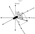
- Such axes are defined in Figure 1 , wherein the forward axis (10) of the device is defined as x-axis, the vertical or z-axis (20) is pointing downward and the transversal axis or y-axis (30) is defined in a way to complete the right handed coordinate system.
- the orientation of a device (50) within a platform is not representative of the orientation of the platform or pedestrian.
- the device may undergo any number of rotational movements along any of its major axes, with respect to the platform. These rotational movements of the device do not indicate that the platform is going through the same changes in orientation.
- the user or platform may be moving on a levelled 2D plane while the device may be undergoing any number of possible roll and pitch angles.
- Figure 1 shows the relationship between an unconstrained device (50) and a pedestrian (60).
- Typical portable devices include a tri-axial accelerometer for measuring accelerations or specific forces, along each of the sensitive axis, i.e., the x-axis, y-axis and the z-axis.
- the device may contain other sensors such as for example gyroscopes, magnetometers, barometer, among others.
- Roll is defined as the rotation of the device along the forward x-axis, while pitch is the rotation along the lateral y-axis. Because the device user is free to rotate the device as desired, the device can have several changes in roll, pitch and azimuth (heading) with respect to the platform.
- the presented method and apparatus uses the accelerometer readings to estimate the misalignment angle.
- the presented method and apparatus is able to give an output at a rate equal to or less than the rate of the accelerometer readings.
- the presented method may take as input a buffer over a pre-determined duration of the following: the accelerometer readings, the roll angle values, and the pitch angle values.
- the method may be taking instantaneous sample values of the accelerometer readings, the roll angle, and the pitch angle, and only buffering the needed quantities in the corresponding steps of the method.
- each sample of the accelerometer readings is levelled using the roll and pitch values of the device.
- the pitch and roll values may be calculated from any one of the following among others: (i) gyroscopes through any one of different methods such as for example quaternions, (ii) accelerometers readings or averaged accelerometer readings (whether fixed-time average or moving average), (iii) integrated navigation solution using any type of integration technique and integrating different sensors and/or systems such as for example some or all of the following: accelerometers, gyroscopes, magnetometers, barometer, odometer, or any navigational information updates (such as, for example, GNSS, WiFi, or any other wireless technique).
- the roll and pitch values used for levelling may be the instantaneous sample values or may be time averaged values (whether fixed time average or moving average) whether buffered or fed to the presented method epoch by epoch (each epoch corresponds to an accelerometer reading sample).
- the operation of levelling the accelerometer readings transforms these readings into two horizontal acceleration components and one vertical component, which is the levelled vertical accelerometer reading.
- the acceleration of the gravity value is removed from the levelled vertical accelerometer data to give the vertical acceleration component.
- the acceleration of the gravity can be obtained in one of different ways including different gravity models or databases.
- the horizontal components are in the North-East plane or the horizontal plane, which is tangential to the Earth's ellipsoid at the current location of the device on Earth.
- the vertical component is perpendicular to this horizontal plane.
- the vertical acceleration component is buffered.
- the horizontal acceleration components buffers (whether calculated from input buffers or from instantaneous inputs and then buffering these in horizontal acceleration buffers) are the input parameters to a technique for obtaining maximum possible variance in the domain of input data.
- the technique used for obtaining maximum possible variance is the PCA technique.
- the two horizontal acceleration buffers are fed to the PCA, which generates the principle components of the two horizontal components buffers.
- An along-track angle is calculated based on the returned values. However, this along-track angle has a 180 degrees ambiguity, i.e.
- a transformation based on the along-track angle (whether it is the correct one or the 180 opposite one) is applied to the levelled horizontal acceleration components. This operation transforms the levelled horizontal acceleration components to give the along-track acceleration component and the side-track (or lateral direction) acceleration component.
- the along-track acceleration component and the vertical acceleration component are buffered for the same predetermined duration if the inputs to the method are not already in buffer format.
- different buffers of data may be used: the along-track acceleration component buffer, the cross-track acceleration component buffer, the vertical acceleration component buffer, the magnitude of the horizontal acceleration buffer, and the magnitude of the 3D acceleration buffer.
- An optional step to make the buffered signals smooth, an LPF may be applied to the buffers.
- the patterns in the acceleration signals in the along-track and vertical buffers may have a different nature based on the device use case.
- a technique for determining or classifying the device use case is run on the along-track and vertical buffers.
- An optional routine to give a misalignment angle output in case the main method gives a "no decision" output may be used, such routine is based on the history of any one or any combination of the following: (i) the buffered history of the along-track angle, (ii) the buffered history of the corrected misalignment angle, (iii) the buffered history of the output of the 180 degrees disambiguity resolution results, (iv) the buffered history of the roll and pitch angles, (v) the buffered history of the azimuth (heading) angle.
- An optional routine to enhance the misalignment angle calculation may be used, such routine is based on the history of any one or any combination of the following: (i) the buffered history of the along-track angle, (ii) the buffered history of the corrected misalignment angle, (iii) the buffered history of the output of the 180 degrees disambiguity resolution results, (iv) the buffered history of the roll and pitch angles, (v) the buffered history of the azimuth (heading) angle.
- This routine may rely on smoothing, averaging, or any type of filtering of any one or any combination of the above list of buffered quantities.
- An optional routine that calculates a standard deviation of the calculated misalignment angle may be used.
- this routine may rely on the consistency of any one or any combination of the following: (i) the buffered history of the along-track angle, (ii) the buffered history of the corrected misalignment angle (one possibility is when it shows continuous flipping meaning frequent error in the 180 degrees disambiguity resolution, so the standard deviation is a function of the ratio of flipping), (iii) the buffered history of the output of the 180 degrees disambiguity resolution results (frequent changes between 0 and 180 degrees needed correction is indicative of erroneous behaviour, so the standard deviation is a function of the ratio of flipping).
- An optional routine to enhance the misalignment angle calculation of the present method when absolute navigational information (such as for example GNSS or WiFi among others) is available and capable of calculating a pedestrian heading may be used.
- the information from (i) and (iii) can be used to calculate another version of misalignment between device and pedestrian that can enhance, be integrated or fused with, be averaged or filtered with the misalignment from (ii).
- the other version of misalignment between device and pedestrian calculated from (i) and (iii) can be used with a machine learning or training technique together with the misalignment from (ii) (especially when the misalignment from (ii) has a poor performance possibly indicated by the optional calculation of its standard deviation) to obtain better misalignment in such use cases even later when the absolute navigational information is blocked, interrupted or degraded.
- both the last two ideas can both be applied in a third embodiment.
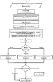
- FIG. 2 A block diagram of one embodiment of the method described in this patent is shown in Figure 2 .
- the optional parts are marked with dotted boxes.
- the present method may be used with a pedestrian dead-reckoning (PDR) solution.
- PDR needs a pedestrian heading (azimuth) together with step detection and step length.
- the sensors in the device such as for example accelerometers, gyroscopes, and magnetometers
- the misalignment angle from the present method can be used with any 2D or 3D navigation application where motion constraints that need this misalignment angle are applied to enhance the positioning or navigation solution (without any physical constraint on the usage of the device) such as, for example:
- this navigation solution can use any type of state estimation or filtering techniques.
- the state estimation technique can be linear, nonlinear or a combination thereof. Different examples of techniques used in the navigation solution may rely on a Kalman filter, an Extended Kalman filter, a nonlinear filter such as a particle filter, or an artificial intelligence technique such as Neural Network or Fuzzy systems.
- the state estimation technique used in the navigation solution can use any type of system and/or measurement models.
- the navigation solution may follow any scheme for integrating the different sensors and systems, such as for example loosely coupled integration scheme or tightly coupled integration scheme among others.
- the navigation solution may utilize modeling (whether with linear or nonlinear, short memory length or long memory length) and/or automatic calibration for the errors of inertial sensors and/or the other sensors used.
- the present disclosure describes the body frame to be x forward, y positive towards right side of the body and z axis positive downwards. It is contemplated that any body-frame definition can be used for the application of the method and apparatus described herein.
- the method and apparatus presented above may be used with a navigation solution that may optionally utilize automatic zero velocity periods or static period detection with possible zero velocity updates and inertial sensors bias recalculations, non-holonomic updates module, advanced modeling and/or calibration of inertial sensors errors, derivation of possible measurements updates for them from GNSS when appropriate, automatic assessment of GNSS solution quality and detecting degraded performance, automatic switching between loosely and tightly coupled integration schemes, assessment of each visible GNSS satellite when in tightly coupled mode, and may also be used with a backward smoothing module with any type of backward smoothing technique and either running in post mission or in the background on buffered data within the same mission.
- the method and apparatus presented above can also be combined with a mode of conveyance technique or a mode detection technique to establish the mode of conveyance. This enables the detection of pedestrian mode among other modes such as for example driving mode.
- the method presented in this disclosure can be made operational to determine the misalignment between the device and the pedestrian.
- the method and apparatus presented above can also be used with a navigation solution that is further programmed to run, in the background, a routine to simulate artificial outages in the absolute navigational information and estimate the parameters of another instance of the state estimation technique used for the solution in the present navigation module to optimize the accuracy and the consistency of the solution.
- the accuracy and consistency is assessed by comparing the temporary background solution during the simulated outages to a reference solution.
- the reference solution may be one of the following examples: the absolute navigational information (e.g. GNSS), the forward integrated navigation solution in the device integrating the available sensors with the absolute navigational information (e.g.
- a backward smoothed integrated navigation solution integrating the available sensors with the absolute navigational information (e.g. GNSS) and possibly with the optional speed or velocity readings.
- the background processing can run either on the same processor as the forward solution processing or on another processor that can communicate with the first processor and can read the saved data from a shared location.
- the outcome of the background processing solution can benefit the real-time navigation solution in its future run (i.e. real-time run after the background routine has finished running), for example, by having improved values for the parameters of the forward state estimation technique used for navigation in the present module.
- the method and apparatus presented above can also be used with a navigation solution that is further integrated with maps (such as street maps, indoor maps or models, or any other environment map or model in cases of applications that have such maps or models available), and a map matching or model matching routine.
- Map matching or model matching can further enhance the navigation solution during the absolute navigation information (such as GNSS) degradation or interruption.
- a sensor or a group of sensors that acquire information about the environment can be used such as, for example, Laser range finders, cameras and vision systems, or sonar systems. These new systems can be used either as an extra help to enhance the accuracy of the navigation solution during the absolute navigation information problems (degradation or absence), or they can totally replace the absolute navigation information in some applications.
- the method and apparatus presented above can also be used with a navigation solution that, when working either in a tightly coupled scheme or a hybrid loosely/tightly coupled option, need not be bound to utilize pseudorange measurements (which are calculated from the code not the carrier phase, thus they are called code-based pseudoranges) and the Doppler measurements (used to get the pseudorange rates).
- the carrier phase measurement of the GNSS receiver can be used as well, for example: (i) as an alternate way to calculate ranges instead of the code-based pseudoranges, or (ii) to enhance the range calculation by incorporating information from both code-based pseudorange and carrier-phase measurements, such enhancement is the carrier-smoothed pseudorange.
- the method and apparatus presented above can also be used with a navigation solution that relies on an ultra-tight integration scheme between GNSS receiver and the other sensors' readings.
- the method and apparatus presented above can also be used with a navigation solution that uses various wireless communication systems that can also be used for positioning and navigation either as an additional aid (which will be more beneficial when GNSS is unavailable) or as a substitute for the GNSS information (e.g. for applications where GNSS is not applicable).
- these wireless communication systems used for positioning are, such as, those provided by cellular phone towers and signals, radio signals, digital television signals, WiFi, or Wimax.
- an absolute coordinate from cell phone towers and the ranges between the indoor user and the towers may be utilized for positioning, whereby the range might be estimated by different methods among which calculating the time of arrival or the time difference of arrival of the closest cell phone positioning coordinates.
- E-OTD Enhanced Observed Time Difference
- the standard deviation for the range measurements may depend upon the type of oscillator used in the cell phone, and cell tower timing equipment and the transmission losses.
- WiFi positioning can be done in a variety of ways that includes but not limited to time of arrival, time difference of arrival, angles of arrival, received signal strength, and fingerprinting techniques, among others; all of the methods provide different level of accuracies.
- the wireless communication system used for positioning may use different techniques for modeling the errors in the ranging, angles, or signal strength from wireless signals, and may use different multipath mitigation techniques. All the above mentioned ideas, among others, are also applicable in a similar manner for other wireless positioning techniques based on wireless communications systems.
- the method and apparatus presented above can also be used with a navigation solution that utilizes aiding information from other moving devices.
- This aiding information can be used as additional aid (that will be more beneficial when GNSS is unavailable) or as a substitute for the GNSS information (e.g. for applications where GNSS based positioning is not applicable).
- One example of aiding information from other devices may be capable of relying on wireless communication systems between different devices. The underlying idea is that the devices that have better positioning or navigation solution (for example having GNSS with good availability and accuracy) can help the devices with degraded or unavailable GNSS to get an improved positioning or navigation solution.
- the wireless communication system used for positioning may rely on different communication protocols, and may rely on different methods, such as for example, time of arrival, time difference of arrival, angles of arrival, and received signal strength, among others.
- the wireless communication system used for positioning may use different techniques for modeling the errors in the ranging and/or angles from wireless signals, and may use different multipath mitigation techniques.
- the proposed technique uses the accelerometer readings to estimate the misalignment angle ( ⁇ mis ) .
- the accelerometer readings are levelled using the roll and pitch values as shown in Figure 3 .
- the gravity value is removed from the levelled vertical accelerometer data to give the vertical acceleration component.
- the horizontal components are the input parameters to the PCA technique which generates the principle components of the horizontal components buffers.
- the along-track angle is calculated based on the components obtained by PCA technique. However, the calculated along-track angle can be either in the forward or backward direction. Different techniques are implemented to solve the problem of the 180 degrees ambiguity and decide if the direction of the motion is forward or backward. To get the motion direction, we apply a transformation based on the along-track angle (whether it is the correct one or the opposite one) to the horizontal axes. This operation transforms the horizontal acceleration components to the along-track motion direction and the side-track direction.
- the logic of the solution for the 180 degrees ambiguity is not the same for all use cases during the implementation.
- the pocket use case has different logic than dangling use case and both of them are different from other use cases. Consequently, we start with procedure by classifying the data into three main categories which are pocket, dangling, or others.
- the use case determination or classification technique fails to recognize dangling or pocket correctly.
- these missed cases are taken into consideration in the general technique. Usually the missed cases behave more like others orientation, therefore some of them can be solved by general methods or special method designed especially for light dangling and light pocket behaviours.
- the accelerometers' data is levelled to the horizontal plan using the estimated roll and pitch values estimated from the system.
- the roll angle is defined as the angle that rotates around x-axis
- pitch angle is defined as the angle that rotates around y-axis.
- DCM direct cosine matrix
- the levelling process transfers x and y accelerometer's data into the horizontal plane and z is the vertical axis.
- Axis z contains gravity component which make its magnitude value bigger than the values of x and y axes. To make all axes have a close range of values, we remove the gravity from the vertical axis. The gravity is removed by subtract the value of g from the vertical component.
- vertical _ vector data _ v z ⁇ g
- PCA is an ordination technique which involves the Eigen-analysis of the data matrix.
- the data matrix is composed of rows corresponding to observations, and columns to variables.
- PCA chooses the first PCA axis as the line that minimizes the square of the distance of each point to that line. Equivalently, this line goes through the maximum variation in the data.
- the first stage in PCA is to standardize the data by subtracting the mean, and then singular value decomposition (SVD) is implemented to get the eigenvectors of x-axis and y-axis.
- SVD singular value decomposition
- the SVD technique used here is Householder transformation which is useful in numerical linear algebra to calculate tri-diagonal and symmetric matrices.
- a n ⁇ 2 P n ⁇ 3 ... P 1 P 0 AP 0 P 1 ... P n ⁇ 3 .
- QR decomposition After getting the tri-diagonal and symmetric matrix ( A n- 2 ), the QR technique is implemented to calculate the eigenvectors and eigenvalues.
- the target matrix ( v *) contains the information of the misalignment angle.
- the first column in v * matrix represents the primary component vector and the second column represents the secondary component vector. It is important to know they are orthogonal vectors. That means the columns are in order of decreasing component variance.
- the first value in the primary component vector means what level the x data's contribution is to the primary component vector and the second value means level of y data's contribution to the primary component.
- the device direction can be estimated using the embedded sensors with the device. Utilizing these sensors can estimate the heading of the device. However, such direction doesn't present the true direction as the device can be held in different orientations rather than the user direction. Holding the device in any orientation makes device heading not identical to the user direction, the difference is called the misalignment angle. As a result, the solution should be corrected or compensated by this angle.
- a misalignment angle estimation technique is implemented based on the PCA technique.
- the portable navigation device can be held in any orientation such as compass, belt, texting, dangling, etc. when the user starts the activity such as walking, running, or driving; there are two major directions; one is the direction of the motion which is identical with the user direction and the second one is the device direction.
- the PCA technique is used to transform the acceleration measurements into a set of uncorrelated variables called the principal components.
- the technique uses the horizontal acceleration, axes x and y data to calculates the principle components for the 2D vector, [ x T y T ] . Therefore, the result of the process generates two principle components; one is called primary component while the second is called the secondary component.
- the plot of the principle components shows that the primary component indicates the approximate value of the misalignment angle.
- the trajectory is divided into windows with 2 seconds data length. For each window there is one primary component vector.
- the accumulated primary components in every window show that a considerable portion of the vector direction is very close to the expected misalignment.
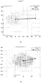
- Figure 4 shows a plot of the scores, measurements, of the samples with 180 degrees misalignment angle.
- the direction of the scores represents the Principal Components (PC) associated with the sample.
- the Ave_PC represents the average vector for all primary principle components.
- the direction of the vector represents the misalignment angle which refers to 0°.
- Figure 4 shows the importance of using 180 degrees correction to adjust the solution to the correct value which is 180 degrees.
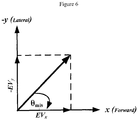
- the misalignment angle can be determined by calculating the angle using the primary component vector. Suppose that:
- the misalignment angle can be estimated from the principle components which are produced by the PCA technique.
- the device's forward direction is already defined in the device frame.
- the pedestrian's forward direction is defined as the motion direction which is a result of both x and y directions.
- the motion direction is calculated by transforming x and y axes into the user plane.
- the resulted vectors are the motion direction vector (along-track) and the lateral direction vector (cross-track).
- motion _ vector lateral _ vector cos ⁇ mis ⁇ sin ⁇ mis sin ⁇ mis cos ⁇ mis x y
- the low pass filter (LPF) is employed for removal high-frequency noise. Consequently, the filtered data becomes smoother and less dependent on short changes. In our application, the behaviour of the user is unexpected and we might get too much change in the signal in short period of time.
- the most important part of the data is the part which is caused by motion of the device. To extract this, a low pass filter with 4 Hz frequency is applied for motion and vertical vectors to reduce the effect of sudden changes on the accelerometer data. This means only signal frequency lower than 4 Hz can pass the filter.
- the present method can work with different devices with different device usages and orientations with respect to the pedestrian.
- Devices include smartphones, tablets, glasses, head-mounts, smartwatches, etc.
- not all use device use cases are applicable for all type of devices. Therefore, there is a routine to provide a flag with the device type to ease the recognition between the different devices.
- the different signals such as motion, lateral, and vertical have different characteristics based on the used device. So, there are methods developed for certain devices or certain uses cases.
- the technique uses the device flag to activate/disable certain parts in the technique.
- the determination of use case which is also referred to herein as “Motion classification", is designed for distinguishing data into three different modes: pocket, dangling and general (which includes belt, hand held, ear talking, chest, backpack, purse, laptop bag, etc.). Since both pocket and dangling movements involve not only trunk force but also additional force from thigh and arm, the relationship between motion signal, vertical signal and attitude signal is no longer consistent with general cases. However, these additional forces sometimes emphasize peaks amplitude; therefore it improves the procedure of detecting peaks and increasing the probability of right solution. In case of normal dangling, the amplitude of motion is much bigger than the amplitude of vertical signal. Signal with such criteria will be classified directly to dangling.
- derived statistics are used to distinguish dangling and pocket data set. Once the dataset is classified into pocket or dangling, these additional forces emphasize peaks amplitude and therefore the procedure of detecting peaks becomes easier.
- the implemented method deals with the device in vertical and horizontal orientation. Different criteria are designed to recognize the slow motion or unpredictable walking behaviour. The implemented methods use statistics values derived from several experiments which includes slow walking, normal walking, women's walking and men's walking.
- the technique starts with determining which attitude gains bigger contribution from the movement to be used. Since some walkers have unexpected and irregular movements, the threshold used in attitude peak detection has to be adapted according the amplitude of signal itself. Due to the additional force from thigh and arm, there is a change or variation in the roll or pitch values according to the device orientation called the attitude changing range while the device orientation, horizontal or vertical, makes the variation to appear in roll or pitch values. A major difference between dangling and pocket is the phenomenon that dangling has a relative consistent and smooth motion curve than vertical signal. The light walkers also are considered in the classification process where the vertical signal for light walkers has less power, the sharp vertical peaks are easily buried under noise.
- This function is used to solve the 180 degrees ambiguity for the pocket orientation through the relationship between thigh attitude, motion feature and vertical signal.
- the proposed technique will only be used after motion classification function when it has been classified into pocket.
- the relationship between motion signal, vertical signal and thigh attitude was built by the relative location of peaks. These experiments include light walker, slow walker, man and woman.
- the proposed technique works with 8 different orientations where 4 orientations have gravity component in x and -x axis, 4 orientations have gravity component in y and -y axis.
- it also has been tested in loose pocket and tight pocket for different types of pocket such as pant pockets (front and back pockets).
- the technique has been tested by unstable motion signal which usually has problem in detecting peaks on signal wave. Finding the peaks of the vertical, motion and attitude signals is the first step in the solution. Each signal has different threshold depending on the signal condition. Since different users have different walking patterns, the threshold will be changed several times to properly detect enough high peaks and low peaks. For detecting motion peaks, light walker style and normal walker style are separated by the condition of vertical data range which is predetermined. If there is no peak detected, the threshold will be reduced according to the walker style. The technique uses the attitude data that has bigger variation. According to the corresponding sign of attitude, a different technique will triggered. There are two representative forward patterns that have the following two series:
- the technique returns the results as Forward/Backward. If for any reason the technique cannot determine if there is a 180 degrees ambiguity or not (Backward/Forward), instead, it will return Undetected.
- the function is used to solve the 180 degrees ambiguity for the dangling orientation through different methods which are implemented to handle different situations in the input data. Different methods are implemented to deal with the different situations in the input data.
- There are 24 different orientations are considered in the dangling mode where 16 orientations in the horizontal and 8 in the vertical.
- the horizontal plan is represented by z, -z, y, and -y axes are having the gravity component while the vertical is represented with x and -x are having the gravity component.
- the proposed technique deals with the normal walking signal.
- the proposed technique solves the problem with the case of strong dangling, normal dangling, light dangling, dangling with different motion speeds, dangling with unstable motion signal, unstable vertical signal, and when the dangling has vertical signal with high amplitude value comparing to the motion signal values.
- peaks are used to make the Forward/Backward decision.
- thresholds values are used to enforce the solution while in other situations they are used to accept or refuse peaks. Some situations are required to be handled prior to others therefore the order of the methods is prepared carefully.
- a pattern of vertical and motion peaks is used to make the decision of Forward/Backward.
- the sign of the motion data slope around the vertical peaks (all peaks, some peaks over or below certain threshold, the maximum peak, or the minimum peak) provides the Forward/Backward decision.
- Finding the peaks of the vertical and motion signals is the first step in the solution.
- peaks are used to make the Forward/Backward decision.
- thresholds values are used to enforcement the solution while in other situations they are used to accept or refuse peaks. Some situations are required to be handled prior to others therefore the order of the methods is prepared carefully.
- the technique returns the results as Forward/Backward. If for any reason the technique cannot determine if there is a 180 degrees ambiguity or not (Backward/Forward), instead, it will return Undetected.
- the implemented method includes several sub-methods to solve the 180 degrees ambiguity for many orientations such as belt, hand held texting or reading, ear talking, backpack, chest, jacket/suit pockets, laptop bag, purse, missed pocket and dangling cases. Some of them have several similarities in statistical values; different criteria are designed to help the technique trigger the appropriate part.
- the implemented methods deal with the device in vertical and horizontal orientation. Different criteria are designed to help in recognizing the slow motion or unpredictable walking behaviour. Also, the implemented methods can deal with the unstable motion behaviour in different use cases such as light walking where the user is not walking properly. The result of the light walking is unstable or distorted motion or vertical signals.
- the use case determination or classification technique fails to classify the pocket or dangling orientations due to unpredictable user behaviour during walking.
- the reason for these exceptions is usually caused by the low standard deviation in motion signal and vertical signal. While standard deviation is small, peaks location becomes very challenging to locate correctly.
- two solutions are provided in this function: (1) Regulation by deleting unreasonable peaks.
- the motion classification sometimes fails to recognize pocket and dangling correctly due to the distortion in the signal.
- Some methods are implemented to handle the cases of missed dangling or missed pocket at normal or slow walking.
- a pattern of vertical and motion peaks is used to make the decision of Forward/Backward.
- the sign of the motion data slope around the vertical peaks gives Forward/Backward decision.
- the 180 degrees ambiguity is detected using the integration of the motion signal by comparing both positive and negative sides of the area under the curve.
- the technique returns the results as Forward/Backward. If for any reason the technique can't decide if there is a 180 degrees ambiguity or not (Backward/Forward), instead, it will return Undetected.
- the 180 degrees ambiguity is solved based on the decision from the different functions.
- the received decision contains three possibilities; forward, backward, or no decision.
- Backward decision means that the direction of the device is opposite to the direction of the motion which requires 180 degrees to be corrected.
- forward decision means that the device is in the same direction of the motion and no correction is needed.
- no decision means that the techniques can't make a decision if it is forward or backward.
- an optional routine to give a misalignment angle output may be used, such routine is based on the history of any one or any combination of the following: (i) the buffered history of the along-track angle, (ii) the buffered history of the corrected misalignment angle, (iii) the buffered history of the output of the 180 degrees disambiguity resolution results, (iv) the buffered history of the roll and pitch angles, (v) the buffered history of the azimuth (heading) angle.
- no decision is to keep the corrected misalignment angle of the last iteration with a decision (iteration is defined as every sample of accelerometer data).
- Example 2 For demonstration purposes, eleven trajectories for walking and running are presented in the coming examples.
- Example 2 there are two trajectories for walking with a navigation-capable prototype.
- Example 3 shows three trajectories for walking with smartphone.
- Two trajectories for walking with tablet are presented in Example 4.
- Walking with Smartwatch in different use cases is illustrated by one trajectory in Example 5.
- Example 6 presents three trajectories for running with the smartphone use cases.
- a low-cost prototype unit for the portable device including a six degrees of freedom inertial unit from Invensense (i.e. tri-axial gyroscopes and tri-axial accelerometer) (MPU-6050), tri-axial magnetometers from Honeywell (HMC5883L), barometer from Measurement Specialties (MS5803), and a GPS receiver from u-blox (LEA-5T) was used to log data for a large number of pedestrian trajectories for different users with different gaits and different speeds.
- Invensense i.e. tri-axial gyroscopes and tri-axial accelerometer
- HMC5883L tri-axial magnetometers from Honeywell
- MS5803 barometer from Measurement Specialties
- LOA-5T GPS receiver from u-blox
- trajectories comprised a lot of different use cases for the prototype device including a lot of handheld in several different orientations, a lot of hand dangling of different types and orientations, a lot of pocket with different types and orientations, a lot of belt with different belt clips in different orientations, a lot of ear.
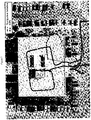
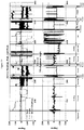
- Figures 7 and Figure 8 show results for the first trajectory.
- Figure 7 shows the positioning results while Figure 8 shows the device heading, roll, and pitch as well as the misalignment between the device and pedestrian.
- the values around 180 degrees can show on top and bottom of the graph (i.e. slightly less than 180 and slightly larger than -180 degrees) which cause them to show vertical lines in the graph between the 180 and -180 degrees.
- the user started outdoor with GPS then went indoor in an office building and walked in two rectangles forming a shape of figure eight in corridors in the building then came out again.
- the misalignment can bring instantaneous values erroneous by 180 degrees because the disambiguity method did take the wrong decision at these epochs.
- the indoor duration was about 2 minutes, and the maximum positioning error was within 7 meters.
- the indoor part did not have any GPS and it did not have any other form of absolute navigational information, but it was a sensor only navigation utilizing the misalignment determination from the presented method.
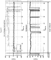
- Figures 9 and Figure 10 show results for the second trajectory.
- Figure 9 shows the positioning results while Figure 10 shows the device heading, roll, and pitch as well as the misalignment between the device and pedestrian.
- the same note in the previous trajectory about the angles being cyclic also causes the same effect in parts of Figure 10 .
- the user started outdoor with GPS then went indoor in the same office building as the previous trajectory and walked in six rectangles in the same corridors in the building then came out again, so the user walked on the same figure eight like the previous trajectory but three times on top of itself.
- Figure 10 shows these different periods together with the attitude angles and the misalignment angle during each period.
- the periods when the user was putting the phone in pocket and getting it out of pocket can also be seen in Figure 10 , as well as their small effect on the navigation solution can be seen in Figure 9 in the middle North-to-South corridor when such transition in and out of pocket happens (some of such transitions took more time than others especially the last one indoors when putting it inside pocket).
- the misalignment angle during the texting portrait was near 0 degrees, also during the dangling the misalignment was near 0 degrees, during the pocket the misalignment was between -45 to -50 degrees, during texting portrait the misalignment was around 0 again, during texting landscape the misalignment was about -90 degrees, during ear the misalignment was around 180 degrees, during dangling it was around 0 degrees, and finally for the pocket the misalignment was between -45 degrees and -50 degrees.
- the first trajectory in very few epochs (i.e.
- the misalignment can bring instantaneous values erroneous by 180 degrees because the disambiguity method did take the wrong decision at these epochs.
- the indoor duration was slightly above 6 minutes, and the maximum positioning error was within 9 meters.
- the indoor part did not have GPS and it did not have any other form of absolute navigational information, but it was a sensor only navigation utilizing the misalignment determination from the presented method.
- Figures 11 shows results for the third trajectory.
- Figure 11 shows the device heading, roll, and pitch as well as the misalignment between a Smartphone and pedestrian.
- This trajectory shows different phone use cases such as compass, texting portrait and landscape, dangling, trouser pocket, belt clip, ear talking, and chest pocket.
- the user started outdoor with GPS then went indoor in the same office building and switched between the different use cases while walking indoors then came out again.
- the user started outdoors with the phone handheld in compass use case, where the roll and pitch angles are almost around zero and the device is in the horizontal plane.
- the phone is used in different ways during the test.
- the misalignment angle during the compass and texting portrait was near 0 degrees, during the texting landscape and dangling the misalignment was near -90 degrees, during the pocket and chest pocket the misalignment was between 45 to 50 degrees, during the ear talking the misalignment was close to 180 degrees, and finally for the texting portrait the misalignment was around 0 again with some epochs giving the wrong estimation misalignment value due to the user opening two consecutive doors to get out of the building.
- very few epochs i.e.
- the misalignment can bring instantaneous values erroneous by 180 degrees because the disambiguity method did take the wrong decision at these epochs.
- the overall impact of these on the navigation solution is minor.
- the indoor duration was slightly above 9 minutes with sensor only navigation utilizing the misalignment determination from the presented method.
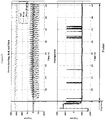
- Figures 12 and Figure 13 show results for the fourth trajectory.
- Figure 12 shows the positioning results while Figure 13 shows the device heading, roll, and pitch as well as the misalignment between the device and pedestrian.
- This trajectory shows the performance of the misalignment technique when the phone was placed in chest pocket.
- the user started outdoor with GPS then went indoor in the same office building as the previous trajectories and walked in one rectangle in the same corridors in the building then came out again, so the user walked on one side of the figure eight.
- the user started with the phone handheld in texting portrait, then before going indoors the user put the phone in the chest pocket and walked in one rectangle and at the end went outside the building again with the phone in texting portrait use case.
- Figure 13 shows these different periods together with the attitude angles and the misalignment angle during each period.
- the periods when the user was putting the phone in the chest pocket can also be seen in Figure 13 , as well as their small effect on the navigation solution can be seen in Figure 12 .
- Figure 13 shows that the pitch angle was changed from 0 to 90 degrees as the device orientation changed from texting portrait to chest pocket, and changed from 90 to 0 degrees when the phone moved again into texting portrait mode.
- the misalignment angle during the texting portrait was near 0 degrees, during the chest pocket the misalignment was around -50 degrees, and finally for the texting portrait the misalignment was around 0 again.
- the trajectory has minor epochs (i.e.
- the misalignment can bring instantaneous values erroneous by 180 degrees because the disambiguity method did take the wrong decision at these epochs.
- the indoor duration was slightly above 1.5 minutes, and the maximum positioning error was within 6 meters.
- the indoor part did not have GPS and it did not have any other form of absolute navigational information, but it was a sensor only navigation utilizing the misalignment determination from the presented method.
- Figures 14 and Figure 15 show results for the fifth trajectory.
- Figure 14 shows the positioning results while Figure 15 shows the device heading, roll, and pitch as well as the misalignment between the device and pedestrian.
- This trajectory shows the performance of the misalignment technique when the phone was placed in the user backpack.
- the user started outdoor with GPS then went indoor in the same office building as the previous trajectories and walked in two rectangles in the same corridors in the building then came out again, so the user walked on one side of the figure eight.
- the user started with the phone handheld in texting portrait and entered the building and walked in one rectangle inside the building, then before starting the second rectangle the user put the device in the backpack and walked in another rectangle and at the end he went outside the building with the device still in the backpack.
- Figure 15 shows these different periods together with the attitude angles and the misalignment angle during each period.
- the periods when the user was putting the phone in the backpack and getting it out of the backpack can also be seen in Figure 15 , as well as their effect on the navigation solution can be seen in Figure 14 .
- the misalignment angle changed from 0 degree to -90 degree with roll angle changed from 0 to 90 degrees when the phone was placed in the backpack.
- the misalignment angle during the texting portrait was near 0 degrees, and finally during carrying in the backpack the misalignment was around -95 degrees.
- the trajectory has minor epochs where the misalignment can bring instantaneous values erroneous by 180 degrees because the disambiguity method did take the wrong decision at these epochs.
- the indoor duration was slightly above 3 minutes, and the maximum positioning error was within 7 meters in the deep indoor navigation.
- the indoor part did not have GPS and it did not have any other form of absolute navigational information, but it was a sensor only navigation utilizing the misalignment determination from the presented method.
- the current example presents two trajectories to show the performance of misalignment estimation technique with a tablet.
- the trajectories cover different tablet use cases with different misalignment angles.
- portrait and landscape is different from phone.
- landscape has a misalignment of 0 degrees instead of the ⁇ 90 degrees for phone.
- Portrait in tablet has a misalignment of either 90 or -90 degrees instead of 0 degrees for phone.
- Figures 16 and Figure 17 show results for the sixth trajectory.
- Figure 16 shows the positioning results while Figure 17 shows the device heading, roll, and pitch as well as the misalignment between the device and pedestrian.
- This trajectory shows the performance of the misalignment technique when the tablet was used in different use cases.
- the user started outdoor with GPS then went indoor in the same office building as the previous trajectories and walked in three rectangles in the same corridors in the building then came out again, so the user walked on one side of the figure eight.
- This trajectory has minor epochs where the misalignment can bring instantaneous values erroneous by 180 degrees because the disambiguity method did take the wrong decision at these epochs.
- the indoor duration was slightly above 4 minutes, and the maximum positioning error was within 8.5 meters in the deep indoor navigation.
- the indoor part did not have GPS and it did not have any other form of absolute navigational information, but it was a sensor only navigation utilizing the misalignment determination from the presented method.
- Figures 18 and Figure 19 show results for the seventh trajectory.
- Figure 18 shows the positioning results while Figure 19 shows the device heading, roll, and pitch as well as the misalignment between the device and pedestrian.
- This trajectory shows the performance of the misalignment technique when the tablet was placed in the user backpack.
- the user started outdoor with GPS then went indoor in the same office building as the previous trajectories and walked in two rectangles in the same corridors in the building then came out again, so the user walked on one side of the figure eight.
- the user started with the tablet handheld in texting landscape then moved into the user backpack outside the building and entered the building with the tablet in the backpack and walked in two rectangles inside the building, and went outside the building having tablet in the backpack.
- Figure 17 shows these different periods together with the attitude angles and the misalignment angle during each period.
- the misalignment angle during the texting landscape was near 0 degrees
- during the dangling was also near 0 degrees
- during texting portrait was 0 degrees
- during the backpack was near 90 degrees.
- the indoor duration was slightly above 2 minutes, and the maximum positioning error was within 10 meters.
- the indoor part did not have GPS and it did not have any other form of absolute navigational information, but it was a sensor only navigation utilizing the misalignment determination from the presented method.
- One trajectory is presented to illustrate the performance of the misalignment estimation technique with a Smartwatch.
- the trajectories cover different Smartwatch use cases with different misalignment angles. Please note that for Smartwatch, the viewing use case refers to watching the time.
- Figures 20 and Figure 21 show results for the eighth trajectory.
- Figure 20 shows the positioning results while Figure 21 shows the device heading, roll, and pitch as well as the misalignment between the device and pedestrian.
- This trajectory shows the performance of the misalignment technique when the Watch was held in the left hand of the user.
- the user started indoor without GPS and walked in two rectangles in the same corridors in the building then stopped, so the user walked on one side of the figure eight.
- the user started with the Watch in viewing (checking the time) then moved into normal walking with dangling.
- Figure 21 shows these different periods together with the attitude angles and the misalignment angle during each period.
- the misalignment angle during the viewing was near 0 degrees and during the dangling was near -170 degrees.
- the test duration was slightly around 1.5 minutes, and the maximum positioning error was within 5 meters. During the test there is no access for GPS or any other form of absolute navigational information, but it was a sensor only navigation utilizing the misalignment determination from the presented
- the following example gives three trajectories to present the performance of the misalignment estimation technique with a Smartphone use cases during running.
- the trajectories cover different running phone use cases with different misalignment angles.
- Figures 22 shows results for the ninth trajectory.
- Figure 22 shows the device heading, roll, and pitch as well as the misalignment between a device and pedestrian during running.
- the trajectory shows arm phone tethered use cases while the user was running in a straight line which can be seen in Figure 22 as the heading is fixed during the trajectory.
- the user fixed the phone to his/her left arm with screen faces out of the body and the speaker pointed up.
- the trajectory shows the running activity while the user is fixing the phone into his/her left arm.
- Figure 22 shows this period together with the attitude angles and the misalignment during the period.
- the misalignment angle during the trajectory was near 95 degrees.
- the misalignment can bring instantaneous values erroneous by 180 degrees because the disambiguity method did take the wrong decision at these epochs.
- Figures 23 shows results for the tenth trajectory.
- Figure 23 shows the device heading, roll, and pitch as well as the misalignment between a device and pedestrian during running.
- the trajectory shows the phone pocket use case while the user was running in a straight line which can be seen in Figure 23 as the heading is fixed during the trajectory.
- the trajectory shows the running activity while the user has the phone in his/her right trouser pant pocket.
- Figure 23 shows this period together with the attitude angles and the misalignment during the period.
- the misalignment angle during the trajectory was near 40 degrees.
- the misalignment can bring instantaneous values erroneous by 180 degrees because the disambiguity method did take the wrong decision at these epochs.
- Figures 24 shows results for the eleventh trajectory.
- Figure 24 shows the device heading, roll, and pitch as well as the misalignment between a device and pedestrian during running.
- the trajectory shows leg phone tethered use cases while the user was running in a straight line which can be seen in Figure 24 as the heading is fixed during the trajectory.
- the user fixed the phone to his/her right leg with screen faces out of the body and the speaker pointed up.
- the trajectory shows the running activity while the user is fixing the phone into his/her right leg.
- Figure 24 shows this period with the attitude angles and the misalignment during the period.
- the misalignment angle during the trajectory was near 95 degrees.
- the misalignment can bring instantaneous values erroneous by 180 degrees because the disambiguity method did take the wrong decision at these epochs.
- the embodiments and techniques described above may be implemented in software as various interconnected functional blocks or distinct software modules. This is not necessary, however, and there may be cases where these functional blocks or modules are equivalently aggregated into a single logic device, program or operation with unclear boundaries.
- the functional blocks and software modules implementing the embodiments described above, or features of the interface can be implemented by themselves, or in combination with other operations in either hardware or software, either within the device entirely, or in conjunction with the device and other processer enabled devices in communication with the device, such as a server.
Landscapes
- Engineering & Computer Science (AREA)
- Radar, Positioning & Navigation (AREA)
- Remote Sensing (AREA)
- Physics & Mathematics (AREA)
- General Physics & Mathematics (AREA)
- General Engineering & Computer Science (AREA)
- Theoretical Computer Science (AREA)
- Automation & Control Theory (AREA)
- Human Computer Interaction (AREA)
- Navigation (AREA)
- Manufacturing & Machinery (AREA)
Claims (9)
- Procédé destiné à déterminer le désalignement entre un dispositif (10) et un piéton (60), dans lequel le désalignement est un angle de désalignement de cap entre un cap du dispositif et un cap du piéton, dans lequel la cap du piéton est une direction de déplacement de piéton, et dans lequel le dispositif comprend un accéléromètre triaxial, le procédé comprenant les étapes consistant à :a) calculer une pluralité de relevés d'accéléromètre égalisés à partir de relevés de l'accéléromètre triaxial en transformant les relevés d'accéléromètre triaxial en une composante de relevé d'accéléromètre verticale égalisée et en des première et seconde composantes d'accélération horizontales ;b) générer une composante d'accélération verticale à partir de la composante de relevé d'accéléromètre verticale égalisée, dans lequel la composante d'accélération verticale est obtenue en enlevant la gravité de la composante de relevé d'accéléromètre verticale égalisée ;c) calculer un angle longitudinal en appliquant une technique de variance possible maximale sur les première et seconde composantes d'accélération horizontales, dans lequel l'angle longitudinal est l'un parmi une direction vers l'avant ou une direction vers l'arrière de l'angle de désalignement de cap ;
dans lequel le procédé comprend en outre les étapes consistant à :d) déterminer un cas d'utilisation du dispositif (10) en se basant au moins en partie sur des modèles des relevés d'accéléromètre égalisés ;e) détecter si une erreur de 180 degrés dans l'angle longitudinal calculé est présente en se basant sur le cas d'utilisation déterminé, dans lequel une ou plusieurs techniques différentes sont utilisées pour détecter si l'erreur de 180 degrés est présente en se basant sur le cas d'utilisation ; etf) calculer un angle de désalignement par rapport à l'angle longitudinal et, le cas échéant, l'erreur de 180 degrés. - Procédé selon la revendication 1, dans lequel le calcul d'un angle longitudinal comprend les étapes consistant à :a) appliquer une analyse de composantes principales sur les première et seconde composantes d'accélération horizontales ;b) calculer un angle longitudinal en utilisant des données de sortie de l'analyse de composantes principales ; etc) transformer les composantes d'accélération horizontales en utilisant l'angle longitudinal pour générer une composante d'accélération longitudinale et une composante d'accélération transversale ;dans lequel l'étape e) de la revendication 1 comprend en outre le fait de détecter si l'erreur de 180 degrés dans l'angle longitudinal est présente en se basant sur le cas d'utilisation, la composante d'accélération longitudinale et la composante d'accélération verticale.
- Procédé selon la revendication 1, dans lequel le calcul d'un angle longitudinal comprend les étapes consistant à :a) appliquer une analyse de composantes principales sur les première et seconde composantes d'accélération horizontales ;b) calculer un angle longitudinal en utilisant des données de sortie de l'analyse de composantes principales, etc) transformer les première et seconde composantes d'accélération horizontales en utilisant l'angle longitudinal pour générer une composante d'accélération longitudinale et une composante d'accélération verticale ;dans lequel l'étape e) de la revendication 1 comprend en outre le fait de détecter si l'erreur de 180 degrés est présente dans l'angle longitudinal en se basant sur le cas d'utilisation, la composante d'accélération longitudinale et la composante d'accélération verticale, ou la déclaration d'aucune décision ; et dans lequel l'étape f) de la revendication 1 comprend en outre le calcul de l'angle de désalignement, dans le cas où e) ne déclare aucune décision, à partir de l'angle longitudinal et, le cas échéant, de l'erreur de 180 degrés.
- Procédé selon l'une des revendications 2 ou 3, dans lequel le fait de détecter si une erreur de 180 degrés est présente dans l'angle longitudinal se base en outre sur une ou plusieurs des composantes suivantes sélectionnées parmi : la composante d'accélération transversale, l'amplitude des première et seconde composantes d'accélération horizontales, ou l'amplitude des première et seconde composantes d'accélération horizontales et de la composante d'accélération verticale.
- Procédé selon la revendication 3, dans lequel si le procédé ne déclare aucune décision, alors il utilise en outre des informations mises en mémoire tampon pour calculer l'angle de désalignement, dans lequel les informations mises en mémoire tampon comprennent un historique de l'un quelconque ou d'une quelconque combinaison parmi :i. l'historique mis en mémoire tampon de l'angle longitudinal ;ii. l'historique mis en mémoire tampon de l'angle de désalignement corrigé ;iii. l'historique mis en mémoire tampon des données de sortie des résultats de résolution de limpidité de 180 degrés ;iv. l'historique mis en mémoire tampon des angles de roulis et de tangage ; etv. l'historique mis en mémoire tampon de l'angle d'azimut (de cap).
- Procédé selon l'une quelconque des revendications 2, 3, 4 ou 5, dans lequel le procédé comprend en outre l'amélioration de l'angle de désalignement en utilisant des informations indépendantes.
- Procédé selon l'une quelconque des revendications 2, 3, 4, 5 ou 6, dans lequel le procédé peut comprendre en outre l'amélioration de l'angle de désalignement calculé à partir d'informations de navigation absolues.
- Procédé selon l'une quelconque des revendications 2, 3, 4, 5, 6 ou 7, dans lequel le procédé peut comprendre en outre le calcul d'un écart-type pour l'angle de désalignement calculé.
- Dispositif (10) portable par un piéton (60) destiné à déterminer un désalignement entre le dispositif et le piéton, dans lequel le désalignement est un angle de désalignement de cap entre un cap du dispositif et un cap du piéton et dans lequel le cap du piéton est une direction de mouvement du piéton, le dispositif comprenant :a) un accéléromètre triaxial ; etb) une unité de traitement, couplée pour recevoir des relevés à partir de l'accéléromètre triaxial, et opérationnelle pour déterminer le désalignement entre le dispositif et le piéton, dans lequel l'unité de traitement est opérationnelle pour :i) calculer une pluralité de relevés d'accéléromètre égalisés à partir de relevés de l'accéléromètre triaxial en transformant les relevés d'accéléromètre triaxial en une composante de relevé d'accéléromètre verticale égalisée et en première et seconde composantes d'accélération horizontales ;ii) générer une composante d'accélération verticale à partir de la composante de relevé d'accéléromètre verticale égalisée, dans lequel la composante d'accélération verticale est obtenue en enlevant la gravité de la composante de relevé d'accéléromètre verticale égalisée ;iii) calculer un angle longitudinal en appliquant une technique de variance possible maximale sur les première et seconde composantes d'accélération horizontales, dans lequel l'angle longitudinal est l'un parmi une direction vers l'avant ou vers l'arrière de l'angle de désalignement de cap,
dans lequel l'unité de traitement est en outre opérationnelle pour :iv) déterminer un cas d'utilisation du dispositif (10) en se basant au moins en partie sur des modèles des relevés d'accéléromètre égalisés ;v) déterminer si une erreur de 180 degrés dans l'angle longitudinal calculé est présente en se basant sur le cas d'utilisation déterminé, dans lequel une ou plusieurs techniques différentes sont utilisées pour déterminer si l'erreur de 180 degrés est présente en se basant sur le cas d'utilisation ; etvi) calculer un angle de désalignement par rapport à l'angle longitudinal et, le cas échéant, l'erreur de 180 degrés.
Applications Claiming Priority (2)
| Application Number | Priority Date | Filing Date | Title |
|---|---|---|---|
| US201361754863P | 2013-01-21 | 2013-01-21 | |
| PCT/CA2014/000040 WO2014110672A1 (fr) | 2013-01-21 | 2014-01-21 | Procédé et appareil de détermination de mauvais alignement entre un dispositif et un piéton |
Publications (3)
| Publication Number | Publication Date |
|---|---|
| EP2946167A1 EP2946167A1 (fr) | 2015-11-25 |
| EP2946167A4 EP2946167A4 (fr) | 2016-10-19 |
| EP2946167B1 true EP2946167B1 (fr) | 2020-02-26 |
Family
ID=51208895
Family Applications (1)
| Application Number | Title | Priority Date | Filing Date |
|---|---|---|---|
| EP14740155.8A Active EP2946167B1 (fr) | 2013-01-21 | 2014-01-21 | Procédé et appareil de détermination de désalignement entre un dispositif et un piéton |
Country Status (5)
| Country | Link |
|---|---|
| US (1) | US10371516B2 (fr) |
| EP (1) | EP2946167B1 (fr) |
| KR (1) | KR20150108402A (fr) |
| CN (1) | CN105074381B (fr) |
| WO (1) | WO2014110672A1 (fr) |
Families Citing this family (42)
| Publication number | Priority date | Publication date | Assignee | Title |
|---|---|---|---|---|
| US9448250B2 (en) * | 2013-06-08 | 2016-09-20 | Apple Inc. | Detecting mount angle of mobile device in vehicle using motion sensors |
| US10132635B2 (en) * | 2013-09-17 | 2018-11-20 | Invensense, Inc. | Method and apparatus for misalignment between device and pedestrian using vision |
| US10652696B2 (en) * | 2014-07-30 | 2020-05-12 | Trusted Positioning, Inc. | Method and apparatus for categorizing device use case for on foot motion using motion sensor data |
| US9767576B2 (en) | 2014-08-22 | 2017-09-19 | Applied Research Associates, Inc. | Techniques for accurate pose estimation in outdoor environments |
| EP3227634B1 (fr) * | 2014-12-03 | 2020-07-29 | Ascom (Sweden) AB | Procédé et système d'estimation d'angle relatif entre des caps |
| US20160161944A1 (en) * | 2014-12-05 | 2016-06-09 | Charles A. Leonard | Vehicle leveling systems, devices and methods and computer program products for leveling vehicles using smart devices |
| US9752879B2 (en) * | 2015-04-14 | 2017-09-05 | Invensense, Inc. | System and method for estimating heading misalignment |
| US9677888B2 (en) * | 2015-06-11 | 2017-06-13 | SenionLab AB | Determining sensor orientation in indoor navigation |
| US10048686B2 (en) * | 2015-11-06 | 2018-08-14 | The Boeing Company | Methods and apparatus to autonomously navigate a vehicle by selecting sensors from which to obtain measurements for navigation |
| US10408627B2 (en) * | 2015-11-30 | 2019-09-10 | Ricoh Company, Ltd. | Inertial device to estimate position based on corrected movement velocity |
| US10184797B2 (en) * | 2015-12-18 | 2019-01-22 | Invensense, Inc. | Apparatus and methods for ultrasonic sensor navigation |
| US10126134B2 (en) * | 2015-12-21 | 2018-11-13 | Invensense, Inc. | Method and system for estimating uncertainty for offline map information aided enhanced portable navigation |
| US10018474B2 (en) * | 2015-12-21 | 2018-07-10 | Invensense, Inc. | Method and system for using offline map information aided enhanced portable navigation |
| CN105704652B (zh) * | 2016-02-16 | 2019-01-04 | 中国科学院光电研究院 | 一种wlan/蓝牙定位中的指纹库采集和优化方法 |
| EP3211371B1 (fr) * | 2016-02-26 | 2020-11-11 | InvenSense, Inc. | Procédé et système pour multiples passages de lissage |
| US10041800B2 (en) * | 2016-09-23 | 2018-08-07 | Qualcomm Incorporated | Pedestrian sensor assistance in a mobile device during typical device motions |
| CN106500722A (zh) * | 2016-09-30 | 2017-03-15 | 深圳市虚拟现实科技有限公司 | 姿态测量装置自动校正的方法及系统 |
| CN108074395B (zh) * | 2016-11-10 | 2020-11-06 | 中国移动通信有限公司研究院 | 一种身份识别的方法及装置 |
| CN106767790B (zh) * | 2017-01-12 | 2019-11-08 | 厦门大学 | 人体下肢运动模型与卡尔曼滤波融合估计行人移动跟踪的方法 |
| CN108537094B (zh) * | 2017-03-03 | 2022-11-22 | 株式会社理光 | 图像处理方法、装置和系统 |
| US10659923B2 (en) | 2017-04-10 | 2020-05-19 | Here Global B.V. | Condition based accurate indoor positioning |
| GB2567889B (en) * | 2017-10-31 | 2021-09-01 | Amer Sports Digital Services Oy | Method and system for determining a direction of movement of an object |
| US12177738B2 (en) | 2017-10-31 | 2024-12-24 | Suunto Oy | Method and system for determining a direction of movement of an object |
| TWI680277B (zh) | 2017-10-31 | 2019-12-21 | 芬蘭商亞瑪芬體育數字服務公司 | 用於確定物體的運動方向的方法和系統 |
| CN107990901B (zh) * | 2017-11-28 | 2021-03-12 | 元力云网络有限公司 | 一种基于传感器的用户方向定位方法 |
| US10809068B2 (en) * | 2017-12-21 | 2020-10-20 | Panasonic Intellectual Property Corporation Of America | Orientation identification method and recording medium |
| US11169577B2 (en) | 2018-04-04 | 2021-11-09 | Microsoft Technology Licensing, Llc | Sensing relative orientation of computing device portions |
| CN109163723A (zh) * | 2018-08-16 | 2019-01-08 | 东南大学 | 一种手机在口袋中摆动时的角度测量方法 |
| CN109540143B (zh) * | 2018-11-27 | 2022-12-02 | 中国广核电力股份有限公司 | 多传感源动态峰值融合的行人非常规动作方向识别方法 |
| KR102825506B1 (ko) | 2019-01-23 | 2025-06-27 | 삼성전자주식회사 | 전자 장치 및 그 제어 방법 |
| CN110006447B (zh) * | 2019-04-04 | 2020-11-10 | 北京临近空间飞行器系统工程研究所 | 一种无需初始对准的任意姿态mems组合定姿方法 |
| US11199410B2 (en) | 2019-04-30 | 2021-12-14 | Stmicroelectronics, Inc. | Dead reckoning by determining misalignment angle between movement direction and sensor heading direction |
| US11747142B2 (en) | 2019-04-30 | 2023-09-05 | Stmicroelectronics, Inc. | Inertial navigation system capable of dead reckoning in vehicles |
| US11017747B2 (en) | 2019-08-16 | 2021-05-25 | Microsoft Technology Licensing, Llc | Systems and methods for adaptive calibration for dynamic rotation of computing device |
| CN111623799B (zh) * | 2020-05-21 | 2022-11-08 | 北京嘀嘀无限科技发展有限公司 | 终端的状态检测方法、装置、终端和存储介质 |
| GB202015887D0 (en) | 2020-10-07 | 2020-11-18 | Veeride Geo Ltd | Hands-free pedestrian navigation system and method |
| CN112902944B (zh) * | 2021-02-04 | 2022-08-26 | 浙江大学 | 补偿光纤陀螺安装和失准角引起的角度测量误差的方法 |
| CN113029153B (zh) * | 2021-03-29 | 2024-05-28 | 浙江大学 | 基于智能手机多传感器融合和svm分类的多场景pdr定位方法 |
| US11680824B1 (en) * | 2021-08-30 | 2023-06-20 | Zoox, Inc. | Inertial measurement unit fault detection |
| EP4457488A4 (fr) * | 2021-12-30 | 2026-04-15 | 3M Innovative Properties Company | Équipement de protection individuelle avec navigation basée sur le mouvement |
| JP7609143B2 (ja) * | 2022-08-26 | 2025-01-07 | カシオ計算機株式会社 | 電子機器、フォーム判定方法及びプログラム |
| CN119618270B (zh) * | 2024-12-30 | 2025-11-07 | 北京航天控制仪器研究所 | 一种单轴框架式惯性导航系统误差标定与补偿方法 |
Family Cites Families (11)
| Publication number | Priority date | Publication date | Assignee | Title |
|---|---|---|---|---|
| GB2146776B (en) * | 1983-09-16 | 1986-07-30 | Ferranti Plc | Accelerometer systems |
| US6826477B2 (en) * | 2001-04-23 | 2004-11-30 | Ecole Polytechnique Federale De Lausanne (Epfl) | Pedestrian navigation method and apparatus operative in a dead reckoning mode |
| US20090138200A1 (en) * | 2007-07-05 | 2009-05-28 | Andrew Hunter | Portable Navigation System |
| EP2263532A1 (fr) * | 2009-06-05 | 2010-12-22 | Koninklijke Philips Electronics N.V. | Appareil de détermination de mouvement |
| CN102013016B (zh) * | 2010-11-23 | 2013-05-08 | 华东理工大学 | 可用于假肢手控制的基于肌音信号手部动作模式识别方法 |
| US8694251B2 (en) * | 2010-11-25 | 2014-04-08 | Texas Instruments Incorporated | Attitude estimation for pedestrian navigation using low cost mems accelerometer in mobile applications, and processing methods, apparatus and systems |
| CN102175244A (zh) * | 2011-03-16 | 2011-09-07 | 公安部沈阳消防研究所 | 基于惯性传感器的建筑物内人员定位系统及定位方法 |
| CA2769788C (fr) * | 2011-03-23 | 2019-08-13 | Trusted Positioning Inc. | Procedes d'estimation de l'attitude et des ecarts d'alignement pour une navigation portative sans contraintes |
| US20130029681A1 (en) * | 2011-03-31 | 2013-01-31 | Qualcomm Incorporated | Devices, methods, and apparatuses for inferring a position of a mobile device |
| US20120296603A1 (en) * | 2011-05-16 | 2012-11-22 | Qualcomm Incorporated | Sensor orientation measurement with respect to pedestrian motion direction |
| CN102214000B (zh) * | 2011-06-15 | 2013-04-10 | 浙江大学 | 用于移动增强现实系统的目标物体混合注册方法及系统 |
-
2014
- 2014-01-21 EP EP14740155.8A patent/EP2946167B1/fr active Active
- 2014-01-21 KR KR1020157022410A patent/KR20150108402A/ko not_active Ceased
- 2014-01-21 CN CN201480017191.0A patent/CN105074381B/zh active Active
- 2014-01-21 WO PCT/CA2014/000040 patent/WO2014110672A1/fr not_active Ceased
- 2014-01-21 US US14/761,156 patent/US10371516B2/en active Active
Non-Patent Citations (1)
| Title |
|---|
| None * |
Also Published As
| Publication number | Publication date |
|---|---|
| US20150354951A1 (en) | 2015-12-10 |
| KR20150108402A (ko) | 2015-09-25 |
| CN105074381A (zh) | 2015-11-18 |
| EP2946167A1 (fr) | 2015-11-25 |
| EP2946167A4 (fr) | 2016-10-19 |
| WO2014110672A1 (fr) | 2014-07-24 |
| CN105074381B (zh) | 2018-12-14 |
| US10371516B2 (en) | 2019-08-06 |
Similar Documents
| Publication | Publication Date | Title |
|---|---|---|
| EP2946167B1 (fr) | Procédé et appareil de détermination de désalignement entre un dispositif et un piéton | |
| US11965741B2 (en) | Methods of attitude and misalignment estimation for constraint free portable navigation | |
| Ban et al. | Indoor positioning method integrating pedestrian Dead Reckoning with magnetic field and WiFi fingerprints | |
| US10184797B2 (en) | Apparatus and methods for ultrasonic sensor navigation | |
| US10337884B2 (en) | Method and apparatus for fast magnetometer calibration | |
| US10429196B2 (en) | Method and apparatus for cart navigation | |
| US11002547B2 (en) | Method for determining the orientation of a sensor frame of reference tied to a mobile terminal carried or worn by a user | |
| US10652696B2 (en) | Method and apparatus for categorizing device use case for on foot motion using motion sensor data | |
| US10302435B2 (en) | Method and system for enhanced navigation with multiple sensors assemblies | |
| US10837794B2 (en) | Method and system for characterization of on foot motion with multiple sensor assemblies | |
| US10830606B2 (en) | System and method for detecting non-meaningful motion | |
| WO2017215024A1 (fr) | Dispositif de navigation pour piétons et procédé basé sur une nouvelle technologie de fusion de multiples capteurs | |
| CN105674984B (zh) | 一种无约束使用移动终端获取行人前进方向的方法 | |
| Ali et al. | An improved personal dead-reckoning algorithm for dynamically changing smartphone user modes | |
| Filardo et al. | C-IPS: A smartphone based indoor positioning system | |
| Herrera et al. | Analysis of a kalman approach for a pedestrian positioning system in indoor environments | |
| CN105874352A (zh) | 使用旋转半径确定设备与船只之间的错位的方法和装置 | |
| Xie et al. | Holding-manner-free heading change estimation for smartphone-based indoor positioning | |
| Ma et al. | An enhanced prototype personal inertial navigation system | |
| Ali et al. | Portable Device Use Case Recognition Technique for Pedestrian Navigation | |
| 양서연 | GPS Carrier Phase/INS Integrated Smartphone Pedestrian Dead-Reckoning Using User Context Classifying Deep Learning | |
| Huang | Self-Contained Pedestrian Tracking With Mems Sensors | |
| Hansen | Human Tracking System |
Legal Events
| Date | Code | Title | Description |
|---|---|---|---|
| PUAI | Public reference made under article 153(3) epc to a published international application that has entered the european phase |
Free format text: ORIGINAL CODE: 0009012 |
|
| 17P | Request for examination filed |
Effective date: 20150813 |
|
| AK | Designated contracting states |
Kind code of ref document: A1 Designated state(s): AL AT BE BG CH CY CZ DE DK EE ES FI FR GB GR HR HU IE IS IT LI LT LU LV MC MK MT NL NO PL PT RO RS SE SI SK SM TR |
|
| AX | Request for extension of the european patent |
Extension state: BA ME |
|
| DAX | Request for extension of the european patent (deleted) | ||
| A4 | Supplementary search report drawn up and despatched |
Effective date: 20160915 |
|
| RIC1 | Information provided on ipc code assigned before grant |
Ipc: G01C 25/00 20060101ALI20160909BHEP Ipc: G01B 21/24 20060101AFI20160909BHEP Ipc: G01C 21/12 20060101ALI20160909BHEP |
|
| STAA | Information on the status of an ep patent application or granted ep patent |
Free format text: STATUS: EXAMINATION IS IN PROGRESS |
|
| 17Q | First examination report despatched |
Effective date: 20180126 |
|
| REG | Reference to a national code |
Ref country code: DE Ref legal event code: R079 Ref document number: 602014061512 Country of ref document: DE Free format text: PREVIOUS MAIN CLASS: G01B0021240000 Ipc: G01C0025000000 |
|
| GRAP | Despatch of communication of intention to grant a patent |
Free format text: ORIGINAL CODE: EPIDOSNIGR1 |
|
| STAA | Information on the status of an ep patent application or granted ep patent |
Free format text: STATUS: GRANT OF PATENT IS INTENDED |
|
| RIC1 | Information provided on ipc code assigned before grant |
Ipc: G06F 3/0346 20130101ALI20191001BHEP Ipc: G01C 21/12 20060101ALI20191001BHEP Ipc: G01C 25/00 20060101AFI20191001BHEP |
|
| INTG | Intention to grant announced |
Effective date: 20191016 |
|
| RIN1 | Information on inventor provided before grant (corrected) |
Inventor name: SYED, ZAINAB Inventor name: ALI, ABDELRAHMAN Inventor name: CHANG, HSIU-WEN Inventor name: GOODALL, CHRISTOPHER Inventor name: GEORGY, JACQUES |
|
| GRAS | Grant fee paid |
Free format text: ORIGINAL CODE: EPIDOSNIGR3 |
|
| GRAA | (expected) grant |
Free format text: ORIGINAL CODE: 0009210 |
|
| STAA | Information on the status of an ep patent application or granted ep patent |
Free format text: STATUS: THE PATENT HAS BEEN GRANTED |
|
| AK | Designated contracting states |
Kind code of ref document: B1 Designated state(s): AL AT BE BG CH CY CZ DE DK EE ES FI FR GB GR HR HU IE IS IT LI LT LU LV MC MK MT NL NO PL PT RO RS SE SI SK SM TR |
|
| REG | Reference to a national code |
Ref country code: GB Ref legal event code: FG4D |
|
| REG | Reference to a national code |
Ref country code: CH Ref legal event code: EP |
|
| REG | Reference to a national code |
Ref country code: AT Ref legal event code: REF Ref document number: 1238184 Country of ref document: AT Kind code of ref document: T Effective date: 20200315 |
|
| REG | Reference to a national code |
Ref country code: IE Ref legal event code: FG4D |
|
| REG | Reference to a national code |
Ref country code: DE Ref legal event code: R096 Ref document number: 602014061512 Country of ref document: DE |
|
| PG25 | Lapsed in a contracting state [announced via postgrant information from national office to epo] |
Ref country code: FI Free format text: LAPSE BECAUSE OF FAILURE TO SUBMIT A TRANSLATION OF THE DESCRIPTION OR TO PAY THE FEE WITHIN THE PRESCRIBED TIME-LIMIT Effective date: 20200226 Ref country code: RS Free format text: LAPSE BECAUSE OF FAILURE TO SUBMIT A TRANSLATION OF THE DESCRIPTION OR TO PAY THE FEE WITHIN THE PRESCRIBED TIME-LIMIT Effective date: 20200226 Ref country code: NO Free format text: LAPSE BECAUSE OF FAILURE TO SUBMIT A TRANSLATION OF THE DESCRIPTION OR TO PAY THE FEE WITHIN THE PRESCRIBED TIME-LIMIT Effective date: 20200526 |
|
| REG | Reference to a national code |
Ref country code: NL Ref legal event code: MP Effective date: 20200226 |
|
| REG | Reference to a national code |
Ref country code: LT Ref legal event code: MG4D |
|
| PG25 | Lapsed in a contracting state [announced via postgrant information from national office to epo] |
Ref country code: BG Free format text: LAPSE BECAUSE OF FAILURE TO SUBMIT A TRANSLATION OF THE DESCRIPTION OR TO PAY THE FEE WITHIN THE PRESCRIBED TIME-LIMIT Effective date: 20200526 Ref country code: IS Free format text: LAPSE BECAUSE OF FAILURE TO SUBMIT A TRANSLATION OF THE DESCRIPTION OR TO PAY THE FEE WITHIN THE PRESCRIBED TIME-LIMIT Effective date: 20200626 Ref country code: GR Free format text: LAPSE BECAUSE OF FAILURE TO SUBMIT A TRANSLATION OF THE DESCRIPTION OR TO PAY THE FEE WITHIN THE PRESCRIBED TIME-LIMIT Effective date: 20200527 Ref country code: LV Free format text: LAPSE BECAUSE OF FAILURE TO SUBMIT A TRANSLATION OF THE DESCRIPTION OR TO PAY THE FEE WITHIN THE PRESCRIBED TIME-LIMIT Effective date: 20200226 Ref country code: SE Free format text: LAPSE BECAUSE OF FAILURE TO SUBMIT A TRANSLATION OF THE DESCRIPTION OR TO PAY THE FEE WITHIN THE PRESCRIBED TIME-LIMIT Effective date: 20200226 Ref country code: HR Free format text: LAPSE BECAUSE OF FAILURE TO SUBMIT A TRANSLATION OF THE DESCRIPTION OR TO PAY THE FEE WITHIN THE PRESCRIBED TIME-LIMIT Effective date: 20200226 |
|
| PG25 | Lapsed in a contracting state [announced via postgrant information from national office to epo] |
Ref country code: NL Free format text: LAPSE BECAUSE OF FAILURE TO SUBMIT A TRANSLATION OF THE DESCRIPTION OR TO PAY THE FEE WITHIN THE PRESCRIBED TIME-LIMIT Effective date: 20200226 |
|
| PG25 | Lapsed in a contracting state [announced via postgrant information from national office to epo] |
Ref country code: SK Free format text: LAPSE BECAUSE OF FAILURE TO SUBMIT A TRANSLATION OF THE DESCRIPTION OR TO PAY THE FEE WITHIN THE PRESCRIBED TIME-LIMIT Effective date: 20200226 Ref country code: PT Free format text: LAPSE BECAUSE OF FAILURE TO SUBMIT A TRANSLATION OF THE DESCRIPTION OR TO PAY THE FEE WITHIN THE PRESCRIBED TIME-LIMIT Effective date: 20200719 Ref country code: LT Free format text: LAPSE BECAUSE OF FAILURE TO SUBMIT A TRANSLATION OF THE DESCRIPTION OR TO PAY THE FEE WITHIN THE PRESCRIBED TIME-LIMIT Effective date: 20200226 Ref country code: DK Free format text: LAPSE BECAUSE OF FAILURE TO SUBMIT A TRANSLATION OF THE DESCRIPTION OR TO PAY THE FEE WITHIN THE PRESCRIBED TIME-LIMIT Effective date: 20200226 Ref country code: RO Free format text: LAPSE BECAUSE OF FAILURE TO SUBMIT A TRANSLATION OF THE DESCRIPTION OR TO PAY THE FEE WITHIN THE PRESCRIBED TIME-LIMIT Effective date: 20200226 Ref country code: EE Free format text: LAPSE BECAUSE OF FAILURE TO SUBMIT A TRANSLATION OF THE DESCRIPTION OR TO PAY THE FEE WITHIN THE PRESCRIBED TIME-LIMIT Effective date: 20200226 Ref country code: SM Free format text: LAPSE BECAUSE OF FAILURE TO SUBMIT A TRANSLATION OF THE DESCRIPTION OR TO PAY THE FEE WITHIN THE PRESCRIBED TIME-LIMIT Effective date: 20200226 Ref country code: ES Free format text: LAPSE BECAUSE OF FAILURE TO SUBMIT A TRANSLATION OF THE DESCRIPTION OR TO PAY THE FEE WITHIN THE PRESCRIBED TIME-LIMIT Effective date: 20200226 Ref country code: CZ Free format text: LAPSE BECAUSE OF FAILURE TO SUBMIT A TRANSLATION OF THE DESCRIPTION OR TO PAY THE FEE WITHIN THE PRESCRIBED TIME-LIMIT Effective date: 20200226 |
|
| REG | Reference to a national code |
Ref country code: AT Ref legal event code: MK05 Ref document number: 1238184 Country of ref document: AT Kind code of ref document: T Effective date: 20200226 |
|
| REG | Reference to a national code |
Ref country code: DE Ref legal event code: R097 Ref document number: 602014061512 Country of ref document: DE |
|
| PLBE | No opposition filed within time limit |
Free format text: ORIGINAL CODE: 0009261 |
|
| STAA | Information on the status of an ep patent application or granted ep patent |
Free format text: STATUS: NO OPPOSITION FILED WITHIN TIME LIMIT |
|
| PG25 | Lapsed in a contracting state [announced via postgrant information from national office to epo] |
Ref country code: IT Free format text: LAPSE BECAUSE OF FAILURE TO SUBMIT A TRANSLATION OF THE DESCRIPTION OR TO PAY THE FEE WITHIN THE PRESCRIBED TIME-LIMIT Effective date: 20200226 Ref country code: AT Free format text: LAPSE BECAUSE OF FAILURE TO SUBMIT A TRANSLATION OF THE DESCRIPTION OR TO PAY THE FEE WITHIN THE PRESCRIBED TIME-LIMIT Effective date: 20200226 |
|
| 26N | No opposition filed |
Effective date: 20201127 |
|
| PG25 | Lapsed in a contracting state [announced via postgrant information from national office to epo] |
Ref country code: SI Free format text: LAPSE BECAUSE OF FAILURE TO SUBMIT A TRANSLATION OF THE DESCRIPTION OR TO PAY THE FEE WITHIN THE PRESCRIBED TIME-LIMIT Effective date: 20200226 Ref country code: PL Free format text: LAPSE BECAUSE OF FAILURE TO SUBMIT A TRANSLATION OF THE DESCRIPTION OR TO PAY THE FEE WITHIN THE PRESCRIBED TIME-LIMIT Effective date: 20200226 |
|
| PG25 | Lapsed in a contracting state [announced via postgrant information from national office to epo] |
Ref country code: MC Free format text: LAPSE BECAUSE OF FAILURE TO SUBMIT A TRANSLATION OF THE DESCRIPTION OR TO PAY THE FEE WITHIN THE PRESCRIBED TIME-LIMIT Effective date: 20200226 |
|
| REG | Reference to a national code |
Ref country code: CH Ref legal event code: PL |
|
| GBPC | Gb: european patent ceased through non-payment of renewal fee |
Effective date: 20210121 |
|
| PG25 | Lapsed in a contracting state [announced via postgrant information from national office to epo] |
Ref country code: LU Free format text: LAPSE BECAUSE OF NON-PAYMENT OF DUE FEES Effective date: 20210121 |
|
| REG | Reference to a national code |
Ref country code: BE Ref legal event code: MM Effective date: 20210131 |
|
| PG25 | Lapsed in a contracting state [announced via postgrant information from national office to epo] |
Ref country code: FR Free format text: LAPSE BECAUSE OF NON-PAYMENT OF DUE FEES Effective date: 20210131 |
|
| PG25 | Lapsed in a contracting state [announced via postgrant information from national office to epo] |
Ref country code: CH Free format text: LAPSE BECAUSE OF NON-PAYMENT OF DUE FEES Effective date: 20210131 Ref country code: GB Free format text: LAPSE BECAUSE OF NON-PAYMENT OF DUE FEES Effective date: 20210121 Ref country code: LI Free format text: LAPSE BECAUSE OF NON-PAYMENT OF DUE FEES Effective date: 20210131 |
|
| PG25 | Lapsed in a contracting state [announced via postgrant information from national office to epo] |
Ref country code: IE Free format text: LAPSE BECAUSE OF NON-PAYMENT OF DUE FEES Effective date: 20210121 |
|
| PG25 | Lapsed in a contracting state [announced via postgrant information from national office to epo] |
Ref country code: BE Free format text: LAPSE BECAUSE OF NON-PAYMENT OF DUE FEES Effective date: 20210131 |
|
| PG25 | Lapsed in a contracting state [announced via postgrant information from national office to epo] |
Ref country code: HU Free format text: LAPSE BECAUSE OF FAILURE TO SUBMIT A TRANSLATION OF THE DESCRIPTION OR TO PAY THE FEE WITHIN THE PRESCRIBED TIME-LIMIT; INVALID AB INITIO Effective date: 20140121 |
|
| PG25 | Lapsed in a contracting state [announced via postgrant information from national office to epo] |
Ref country code: CY Free format text: LAPSE BECAUSE OF FAILURE TO SUBMIT A TRANSLATION OF THE DESCRIPTION OR TO PAY THE FEE WITHIN THE PRESCRIBED TIME-LIMIT Effective date: 20200226 |
|
| PG25 | Lapsed in a contracting state [announced via postgrant information from national office to epo] |
Ref country code: MK Free format text: LAPSE BECAUSE OF FAILURE TO SUBMIT A TRANSLATION OF THE DESCRIPTION OR TO PAY THE FEE WITHIN THE PRESCRIBED TIME-LIMIT Effective date: 20200226 |
|
| PG25 | Lapsed in a contracting state [announced via postgrant information from national office to epo] |
Ref country code: MT Free format text: LAPSE BECAUSE OF FAILURE TO SUBMIT A TRANSLATION OF THE DESCRIPTION OR TO PAY THE FEE WITHIN THE PRESCRIBED TIME-LIMIT Effective date: 20200226 |
|
| PG25 | Lapsed in a contracting state [announced via postgrant information from national office to epo] |
Ref country code: TR Free format text: LAPSE BECAUSE OF FAILURE TO SUBMIT A TRANSLATION OF THE DESCRIPTION OR TO PAY THE FEE WITHIN THE PRESCRIBED TIME-LIMIT Effective date: 20200226 |
|
| PGFP | Annual fee paid to national office [announced via postgrant information from national office to epo] |
Ref country code: DE Payment date: 20251203 Year of fee payment: 13 |