EP2946736A1 - Dispositif de traitement - Google Patents
Dispositif de traitement Download PDFInfo
- Publication number
- EP2946736A1 EP2946736A1 EP14740623.5A EP14740623A EP2946736A1 EP 2946736 A1 EP2946736 A1 EP 2946736A1 EP 14740623 A EP14740623 A EP 14740623A EP 2946736 A1 EP2946736 A1 EP 2946736A1
- Authority
- EP
- European Patent Office
- Prior art keywords
- wire
- loop
- treatment device
- jaws
- grasping member
- Prior art date
- Legal status (The legal status is an assumption and is not a legal conclusion. Google has not performed a legal analysis and makes no representation as to the accuracy of the status listed.)
- Withdrawn
Links
- 230000033001 locomotion Effects 0.000 claims abstract description 19
- 210000001519 tissue Anatomy 0.000 description 112
- 230000001338 necrotic effect Effects 0.000 description 55
- 238000000034 method Methods 0.000 description 32
- 238000003780 insertion Methods 0.000 description 19
- 230000037431 insertion Effects 0.000 description 19
- 210000002784 stomach Anatomy 0.000 description 15
- 210000000496 pancreas Anatomy 0.000 description 14
- 210000004204 blood vessel Anatomy 0.000 description 8
- 239000000126 substance Substances 0.000 description 8
- 230000000694 effects Effects 0.000 description 6
- 229910045601 alloy Inorganic materials 0.000 description 4
- 239000000956 alloy Substances 0.000 description 4
- 238000001828 necrosectomy Methods 0.000 description 4
- 238000002679 ablation Methods 0.000 description 3
- 230000003247 decreasing effect Effects 0.000 description 3
- 238000004299 exfoliation Methods 0.000 description 3
- 230000003902 lesion Effects 0.000 description 3
- 239000000463 material Substances 0.000 description 3
- 238000003825 pressing Methods 0.000 description 3
- 230000005540 biological transmission Effects 0.000 description 2
- 239000002184 metal Substances 0.000 description 2
- 229910001000 nickel titanium Inorganic materials 0.000 description 2
- 230000001151 other effect Effects 0.000 description 2
- 239000010935 stainless steel Substances 0.000 description 2
- 229910001220 stainless steel Inorganic materials 0.000 description 2
- 229920000742 Cotton Polymers 0.000 description 1
- 239000004677 Nylon Substances 0.000 description 1
- 238000007792 addition Methods 0.000 description 1
- 230000000740 bleeding effect Effects 0.000 description 1
- 238000006243 chemical reaction Methods 0.000 description 1
- 210000003238 esophagus Anatomy 0.000 description 1
- 238000012986 modification Methods 0.000 description 1
- 230000004048 modification Effects 0.000 description 1
- 229920001778 nylon Polymers 0.000 description 1
- 210000004923 pancreatic tissue Anatomy 0.000 description 1
- 230000001575 pathological effect Effects 0.000 description 1
- 239000011347 resin Substances 0.000 description 1
- 229920005989 resin Polymers 0.000 description 1
- 239000000523 sample Substances 0.000 description 1
- 229910001285 shape-memory alloy Inorganic materials 0.000 description 1
- 239000002356 single layer Substances 0.000 description 1
- 238000006467 substitution reaction Methods 0.000 description 1
- 238000001356 surgical procedure Methods 0.000 description 1
- 230000008961 swelling Effects 0.000 description 1
Images










Classifications
-
- A—HUMAN NECESSITIES
- A61—MEDICAL OR VETERINARY SCIENCE; HYGIENE
- A61B—DIAGNOSIS; SURGERY; IDENTIFICATION
- A61B10/00—Instruments for taking body samples for diagnostic purposes; Other methods or instruments for diagnosis, e.g. for vaccination diagnosis, sex determination or ovulation-period determination; Throat striking implements
- A61B10/02—Instruments for taking cell samples or for biopsy
- A61B10/06—Biopsy forceps, e.g. with cup-shaped jaws
-
- A—HUMAN NECESSITIES
- A61—MEDICAL OR VETERINARY SCIENCE; HYGIENE
- A61B—DIAGNOSIS; SURGERY; IDENTIFICATION
- A61B17/00—Surgical instruments, devices or methods
- A61B17/22—Implements for squeezing-off ulcers or the like on inner organs of the body; Implements for scraping-out cavities of body organs, e.g. bones; for invasive removal or destruction of calculus using mechanical vibrations; for removing obstructions in blood vessels, not otherwise provided for
- A61B17/22031—Gripping instruments, e.g. forceps, for removing or smashing calculi
-
- A—HUMAN NECESSITIES
- A61—MEDICAL OR VETERINARY SCIENCE; HYGIENE
- A61B—DIAGNOSIS; SURGERY; IDENTIFICATION
- A61B17/00—Surgical instruments, devices or methods
- A61B17/22—Implements for squeezing-off ulcers or the like on inner organs of the body; Implements for scraping-out cavities of body organs, e.g. bones; for invasive removal or destruction of calculus using mechanical vibrations; for removing obstructions in blood vessels, not otherwise provided for
- A61B17/221—Gripping devices in the form of loops or baskets for gripping calculi or similar types of obstructions
-
- A—HUMAN NECESSITIES
- A61—MEDICAL OR VETERINARY SCIENCE; HYGIENE
- A61B—DIAGNOSIS; SURGERY; IDENTIFICATION
- A61B17/00—Surgical instruments, devices or methods
- A61B17/28—Surgical forceps
- A61B17/29—Forceps for use in minimally invasive surgery
- A61B17/295—Forceps for use in minimally invasive surgery combined with cutting implements
-
- A—HUMAN NECESSITIES
- A61—MEDICAL OR VETERINARY SCIENCE; HYGIENE
- A61B—DIAGNOSIS; SURGERY; IDENTIFICATION
- A61B17/00—Surgical instruments, devices or methods
- A61B17/32—Surgical cutting instruments
- A61B17/3205—Excision instruments
- A61B17/32056—Surgical snare instruments
-
- A—HUMAN NECESSITIES
- A61—MEDICAL OR VETERINARY SCIENCE; HYGIENE
- A61B—DIAGNOSIS; SURGERY; IDENTIFICATION
- A61B17/00—Surgical instruments, devices or methods
- A61B17/00234—Surgical instruments, devices or methods for minimally invasive surgery
- A61B2017/00238—Type of minimally invasive operation
- A61B2017/00269—Type of minimally invasive operation endoscopic mucosal resection EMR
-
- A—HUMAN NECESSITIES
- A61—MEDICAL OR VETERINARY SCIENCE; HYGIENE
- A61B—DIAGNOSIS; SURGERY; IDENTIFICATION
- A61B17/00—Surgical instruments, devices or methods
- A61B17/00234—Surgical instruments, devices or methods for minimally invasive surgery
- A61B2017/00353—Surgical instruments, devices or methods for minimally invasive surgery one mechanical instrument performing multiple functions, e.g. cutting and grasping
-
- A—HUMAN NECESSITIES
- A61—MEDICAL OR VETERINARY SCIENCE; HYGIENE
- A61B—DIAGNOSIS; SURGERY; IDENTIFICATION
- A61B17/00—Surgical instruments, devices or methods
- A61B17/00234—Surgical instruments, devices or methods for minimally invasive surgery
- A61B2017/00358—Snares for grasping
-
- A—HUMAN NECESSITIES
- A61—MEDICAL OR VETERINARY SCIENCE; HYGIENE
- A61B—DIAGNOSIS; SURGERY; IDENTIFICATION
- A61B17/00—Surgical instruments, devices or methods
- A61B17/28—Surgical forceps
- A61B17/29—Forceps for use in minimally invasive surgery
- A61B2017/2901—Details of shaft
-
- A—HUMAN NECESSITIES
- A61—MEDICAL OR VETERINARY SCIENCE; HYGIENE
- A61B—DIAGNOSIS; SURGERY; IDENTIFICATION
- A61B17/00—Surgical instruments, devices or methods
- A61B17/28—Surgical forceps
- A61B17/29—Forceps for use in minimally invasive surgery
- A61B17/2909—Handles
- A61B2017/2912—Handles transmission of forces to actuating rod or piston
- A61B2017/2923—Toothed members, e.g. rack and pinion
-
- A—HUMAN NECESSITIES
- A61—MEDICAL OR VETERINARY SCIENCE; HYGIENE
- A61B—DIAGNOSIS; SURGERY; IDENTIFICATION
- A61B17/00—Surgical instruments, devices or methods
- A61B17/28—Surgical forceps
- A61B17/29—Forceps for use in minimally invasive surgery
- A61B2017/2926—Details of heads or jaws
-
- A—HUMAN NECESSITIES
- A61—MEDICAL OR VETERINARY SCIENCE; HYGIENE
- A61B—DIAGNOSIS; SURGERY; IDENTIFICATION
- A61B17/00—Surgical instruments, devices or methods
- A61B17/28—Surgical forceps
- A61B17/29—Forceps for use in minimally invasive surgery
- A61B2017/2926—Details of heads or jaws
- A61B2017/2927—Details of heads or jaws the angular position of the head being adjustable with respect to the shaft
- A61B2017/2929—Details of heads or jaws the angular position of the head being adjustable with respect to the shaft with a head rotatable about the longitudinal axis of the shaft
Definitions
- the present invention relates to a treatment device.
- a procedure of endoscopically excising a lesion or the like is known.
- a treatment device used in such a procedure a treatment device used with an endoscope apparatus in order to collect the excised lesion or the like is known.
- Patent Document 1 a wire for removing foreign substances in a blood vessel which includes two loop-shaped sandwiching portions formed at a distal end side of an elongated wire main body having flexibility is disclosed.
- the foreign substances in the blood vessel can be sandwiched and collected by being reduced the distance between the sandwiching portions by moving the two loop-shaped sandwiching portions relative to each other.
- Patent Document 2 a tissue ablation apparatus configured to advance or retreat an exfoliation loop and a cutting loop with respect to a probe is disclosed.
- the exfoliation loop and the cutting loop can be moved between a receiving position and an open position.
- a cup type forceps and a basket type forceps are used as a treatment device for necrosectomy. Sizes of the cup type forceps or the basket type forceps to be conventionally used are limited so as to be inserted into the endoscope channel of the flexible endoscope apparatus. Therefore, in the cup type forceps or the basket type forceps, volumes of a cup or a basket must need to much smaller than a volume of a whole of the necrotic tissue which is desired to be removed once. As a result, since a step of collecting the necrotic tissue and a step of disposing the necrotic tissue are needed to repeat a number of time, the treatment needs to take a lomg time.
- the wire for removing foreign substances in the blood vessel disclosed in Patent Document 1 is not a treatment device used for necrosectomy originally, if the wire for removing foreign substances in the blood vessel is used, only a small amount of tissue can be removed. Therefore, an operation in which the wire is inserted into and is extracted from the endoscope is needed to repeat, and the treatment needs to take a lomg time.
- the wire may become difficult to be removed from the treatment device because a grasped necrotic tissue may be adhered to the treatment device. That is, the treatment needs to take a long time and the burden to the patient increase is concerned.
- an operation of opening a looped shaped grasping portion in accordance with a condition and a hardness of the tissue is hard to operate.
- the wire for removing foreign substances in the blood vessel has a fatal problem such that a tissue which has a width in a direction perpendicular to the longitudinal axis of the longitudinal member is hard to grasp.
- the present invention has been made in view of this problem, and an objective of the invention is to provide a treatment device which is capable of removing the large amount of the tissue with one manipulation in comparison with the case in which the tissue is removed using a general forceps.appropriately gripping a target to be gripped, and which is capable of efficiently performing a collecting operation according to the size of the tissue serving as the collecting target.
- a treatment device includes a longitudinal member having a longitudinal axis; a pair of jaws installed at a distal end of the longitudinal member and configured to be opened and closed in a direction crossing the longitudinal axis of the longitudinal member by being operated to open and close; a first grasping member supported by a first jaw of the pair of jaws and including a linear members annularly curved within a plane crossing an opening-closing direction of the jaws; and a second grasping member supported by a second jaw of the pair of jaws, the second grasping member configured to open and close with respect to the first grasping member with an open-close motion of the pair of jaws, the second grasping member configured to apply a grasping force with the first grasping member to an object to be grasped when the second grasping member is closed.
- the second grasping member may include a linear member which is curved in the annular shape within a plane crossing an open-close direction of the pair of jaws.
- the second grasping member may consist of a plate-shaped member having a grasping surface crossing the open-close direction of the pair of jaws.
- the linear member may be a flexible wire.
- the linear member which constitutes the first grasping member may be a flexible wire being curved in a loop shape.
- the wire in the treatment device according to the fifth aspect, may be configured such that a loop size in a plane crossing to an open-close direction of the jaw is freely enlarged or reduced.
- the longitudinal member may have a tube shape, an operation wire for varying the loop size of the wire may be provided inside the longitudinal member.
- the wire in the treatment device according to the sixth aspect, may be provided so as to advance in a direction protruding from the jaws and to retreat in a direction being accommodated in the jaws, the wire may be configured to such that a loop size in a plane crossing to an open-close direction of the jaw is freely enlarged or reduced by an advance-retreat motion of the wire.
- the linear members which constitute each of the first grasping member and the second grasping member may be flexible wires being curved in a loop shape respectively, each of the wires may be provided so as to advance in a direction protruding from the jaws and to retreat in a direction being accommodated in the jaws respectively, the wires may be configured to such that loop sizes in a plane crossing to an open-close direction of the jaw are freely and independently enlarged or reduced by an advance-retreat motion of the wire.
- a convex portion formed to protrude at a grasp side with respect to the object to be grasped may be provided at the wire which constitutes the first grasping member.
- the wire which constitutes the first grasping member may be set so as to incline to a position further inside than a position of the jaw which supports the first grasping member.
- the linear members which constitute the first grasping member and the second grasping member may be formed by flexible wires respectively, when the first grasping member and the second grasping member are closed, the wires may be set so as to incline to a position further inside than a position of the pair of jaws, and one wire may be set to enter a space inside of the loop shape of the other wire.
- a net stretched on a plane surrounding the wire may be installed at the wire.
- the linear member constituting the first grasping member is a flexible wire which is curved in a spiral shape.
- the first grasping member may include a plurality of flexible wires curved in the loop shape as the linear member curved in the annular shape, the plurality of wires may include a main wire and an auxiliary wire, the main wire which is positioned at an outward, the main wire in which a loop size may be formed large, the auxiliary wire in which a loop size may be formed to be smaller than the loop size of the main wire, the auxiliary wire may be disposed to have an interval inside the main loop wire.
- the first grasping member and the second grasping member may include a plurality of flexible wires curved in the loop shape as the linear member curved in the annular shape
- the plurality of wires may include a main wire and an auxiliary wire, the main wire which may be positioned at an outward, the main wire in which a loop size may be formed large, the auxiliary wire in which a loop size may be formed to be smaller than the loop size of the main wire, the auxiliary wire may be disposed to have an interval inside the main loop wire.
- a loop shape of the auxiliary wire of one grasping member and the second grasping member and a loop size of the auxiliary wire of the another grasping member may be different from each other
- a centerline of the main wire connecting between a point where the main wire supported by the jaws and a point where maximally spaced apart from the jaws, and a centerline of the auxiliary wire connecting between a point where the auxiliary wire supported by the jaws and a point where maximally spaced apart from the jaw may be positioned so as to overlap in the same plane including both of the main wire and the auxiliary wire.
- a plane including the main wire and a plane including the auxiliary wire may have a relation in which they are parallel to each other with an interval therebetween, a center line of the main wire connecting between a point where the main wire supported by the jaws and a point where maximally spaced apart from the jaws and a centerline of the auxiliary wire connecting between a point where the auxiliary wire supported by the jaws and a point where maximally spaced apart from the jaw may be positioned so as to overlap when seen in a direction perpendicular to the plane.
- a plane including the main wire and a plane including the auxiliary wire may have a relation in which they form an inclined angle to each other, a center line of the main wire connecting between a point where the main wire supported by the jaws and a point where maximally spaced apart from the jaws and a centerline of the auxiliary wire connecting between a point where the auxiliary wire supported by the jaws and a point where maximally spaced apart from the jaw may be positioned so as to overlap when seen in a direction perpendicular to the plane including the main loop wire.
- a centerline of the main wire connecting between a point where the main wire being supported by the jaws and a point where maximally spaced apart from the jaws, and a centerline of the auxiliary wire connecting between a point where the auxiliary wire being supported by the jaws and a point where maximally spaced apart from the jaws may be deviated from each other when seen in a direction perpendicular to a plane including the main wire.
- a convex portion formed to protrude at a grasp side with respect to the object to be grasped may be provided at the auxiliary wire.
- the main wires and the auxiliary wires may be set to be inclined toward further inside positions than positions of the pair of jaws when the first grasping member and the second grasping member are closed.
- the main wire and the auxiliary wire when the first grasping member and the second grasping member are closed, the main wire and the auxiliary wire may be inclined toward further inside positions of the pair of jaws and at least one of the main wire and the auxiliary wire that constitute the first grasping member of the first grasping member and the second grasping member is set to enter a space inside the loop shape of at least one of the main wire and the auxiliary wire of the second grasping member.
- the linear member which constitutes the first grasping member may be flexible half loop wires being curved in a half loop shape, both ends of the half loop wire may be inserted through through-holes formed in a distal end surfaces of the jaws and are extended toward the longitudinal member.
- the half loop wire in the treatment device according to the twenty-fifth aspect, may be provided so as to advance in a direction protruding from the jaws and to retreat in a direction being accommodated in the jaws, the half loop wire may be configured to such that a half loop size in a plane crossing to an open-close direction of the jaw is freely enlarged or reduced by an advance-retreat motion of the half loop wire.
- At least one of the first grasping member and the second grasping member may consist of a flexible half loop wires curved in a half loop shape
- the half loop wire may be provided as the linear member
- the half loop wire may be provided at the jaw so as to be freely advance and retreat
- the half loop wire may be configured to such that a loop size in a plane crossing to an open-close direction of the jaw is freely enlarged or reduced by an advance-retreat motion of the half loop wire.
- both of the first grasping member and the second grasping member may include a flexible half loop wire curved in a half loop shape
- the half loop wires are provided as the linear member
- the half loop wires may be provided at the jaw so as to be freely advance and retreat
- the half loop wires may be configured to such that loop sizes in a plane crossing to an open-close direction of the jaw are freely enlarged or reduced by an advance-retreat motion of the wire curved in the half loop shape.
- the first grasping member may include a flexible half loop wire curved in a half loop shape
- the half loop wire may be provided as the linear member
- the half loop wire may be a main wire and an auxiliary wire, the main wire which is positioned at an outward, the main wire in which a loop size is formed large, the auxiliary wire in which a loop size may be formed to be smaller than the loop size of the main wire, the auxiliary wire may be disposed to have an interval inside the main loop wire.
- the first grasping member may include a main grasping member consisting of a flexible wire curved in a loop shape and an auxiliary grasping member which has plate shape and may be disposed to have an interval inside the main grasping member, the auxiliary grasping member may be provided fixedly at a distal end of the jaw.
- the first grasping member may include a main grasping member consisting of a flexible half loop wire curved in a half loop shape and an auxiliary grasping member which has plate shape and may be disposed to have an interval inside the main grasping member, the auxiliary grasping member may be provided fixedly at a distal end of the jaw, both ends of the half loop wire constituted the main grasping member may be inserted through through-holes formed in a distal end surfaces of the jaws and may be extended toward the longitudinal member.
- the treatment device may further include an operating portion connected to at least one of the first grasping member and the second grasping member installed at a proximal end of the longitudinal member, wherein the first grasping member may be consisted of a plurality of flexible wire curved in the loop shape, the wire may be provided as the linear member curved in the annular shape.
- the plurality of wire curved in the loop shape may have: a main wire having the loop shape; and an auxiliary wire in which a loop size is formed to be smaller than the loop size of the main wire, the auxiliary wire is disposed to have an interval inside the main loop wire.
- the operating portion may have: a first movable member configured to advance and retract the main wire in a central axis direction of the longitudinal member; and a second movable member configured to advance and retract the auxiliary wire in the central axis direction of the longitudinal member.
- the first movable member may be a first pulley in which the main wire is suspended on an outer circumference thereof
- the second movable member may be a second pulley of which the auxiliary wire is suspended on an outer circumference thereof
- the first pulley may have a larger diameter than that of the second pulley
- the first pulley and the second pulley are integrally rotatable about the same rotational center.
- the treatment device may further include a rotary shaft concentric with the rotational center and fixed to the first pulley and the second pulley; and a dial installed at a portion of the rotary shaft positioned outside the operating portion and rotated by an operator.
- the treatment device may further include, a pinion connected to the first pulley and the second pulley; a rack meshed with the pinion and disposed in the operating portion; and a slider formed at a portion of the rack, disposed outside the operating portion, and being advanced and retreated in a lengthwise direction of the rack by an operator.
- the treatment device may further include a first slider serving as the first movable member, fixed to the main wire, disposed at the operating portion, and configured to advance and retreat in a predetermined direction in the operating portion; a second slider serving as the second movable member, fixed to the auxiliary wire, disposed at the operating portion, and configured to advance and retreat in the predetermined direction; and a stopper installed at the first slider and configured to limit movement of the second slider to the distal end side farther than the first slider wherein the second slider may be configured to freely advance and retreat in the predetermined direction when the second slider is disposed to be spaced apart from the first slider farther than the proximal end side in the operating portion, and the second slider may be configured to be capable of moving to the proximal end side of the operating portion while abutting the stopper, and moving to the distal end side of the operating portion only upon moving to the distal end side of the operating portion with the first slider.
- a first slider serving as the first movable member, fixed to the main wire, disposed at the
- the large amount of the tissue can be removed with one manipulation in comparison with the case in which the tissue is removed using a general forceps.
- a collecting operation can be efficiently performed according to the size of the tissue serving as the collecting target.
- FIG. 1 is an overall view showing the treatment device of the embodiment and an endoscope apparatus 500 used with the treatment device.
- a treatment device 1A is a treatment device used with the endoscope apparatus 500.
- a configuration of the endoscope apparatus 500 used with the treatment device 1A is not particularly limited.
- the endoscope apparatus 500 is a flexible endoscope including a flexible insertion portion 501 inserted into the stomach from the mouth and an endoscope channel 502 configured to be inserted into the treatment device 1A and installed in the insertion portion 501.
- the treatment device 1A includes a treatment portion 10, an insertion portion 2 and an operating portion 100.
- the treatment portion 10 is used for treatment in the body.
- the treatment portion 10 is installed at a distal end of the insertion portion 2.
- the operating portion 100 is installed at a proximal end of the insertion portion 2.
- the treatment device 1A will be described by defining a side at which the treatment portion 10 is installed as a distal end side and a side at which the operating portion 100 is installed as a proximal end side.
- the insertion portion 2 is a member inserted into the endoscope channel 502 of the endoscope apparatus 500 such as a flexible endoscope or the like.
- the insertion portion 2 is inserted into the endoscope channel 502 from the distal end of the insertion portion 2.
- the insertion portion 2 includes a longitudinal member 3 having a longitudinal axis.
- the longitudinal member 3 is a tubular member with a distal end side and a proximal end side opened.
- the longitudinal member 3 has flexibility such that the longitudinal member 3 can advance and retreat in the endoscope channel 502 even when the endoscope channel 502 of the endoscope apparatus 500 is curved.
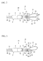
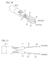
- FIGS. 2 and 3 are perspective views of the treatment portion of the distal end of the treatment device 1A according to the embodiment.
- the treatment portion 10 is installed at the distal end of the longitudinal member 3 of the insertion portion 2.
- a pair of jaws 11 and 12 constituted by a first jaw 11 and a second jaw 12 (which may hereinafter be referred to as “the jaws 11 and 12") are installed at the treatment portion 10.
- the pair of jaws 11 and 12 are simultaneously opened and closed in an arrow A1 direction crossing a longitudinal axis of the longitudinal member 3.
- the first jaw 11 and the second jaw 12 are supported at a cylindrical housing 4 fixed to the distal end of the longitudinal member 3.
- the first jaw 11 and the second jaw 12 are manipulated to be opened and closed by the operating portion 100.
- a first grasping member 21 and a second grasping member 22 configured to be opened and closed with the jaws 11 and 12 are installed at the distal end sides of the first jaw 11 and the second jaw 12, respectively.
- the first grasping member 21 and the second grasping member 22 (which may hereinafter be referred to as "the grasping members 21 and 22") are grasp portions configured to collect a tissue or the like (including a necrotic tissue), which is an object to be grasped such as a lesion area or the like.
- the first grasping member 21 and the second grasping member 22 are opened and closed in an arrow A2 direction, which is the same as the open-close direction of the jaws 11 and 12 shown by the arrow A1.
- the grasping members 21 and 22 exert a grasping force on a tissue or the like, which is the object to be grasped d, upon closing such that the object to be grasped can be grasped.
- the grasping members 21 and 22 include linear members annularly curved within a plane crossing the open-close direction of the jaws 11 and 12 (the arrow A1 direction of FIG. 2 ).
- the grasping members 21 and 22 are constituted by wires 23 having flexibility and curved in a loop shape (hereinafter referred to as "a loop wire").
- the loop wires 23 are formed to exit distal end openings 13 of the jaws 11 and 12 to return to the distal end opening 13 of the jaws 11 and 12 while forming a loop similar to a circular or oval shape, or the like. Starting ends and terminating ends of the loop wires 23 are formed to be pulled into the distal end openings 13 of the jaws 11 and 12.
- the starting ends and the terminating ends of the loop wires 23 pulled into the distal end openings 13 of the jaws 11 and 12 are coupled to distal ends of advance-retreat manipulation wires 31 and 32, for example, in the jaws 11 and 12.
- the advance-retreat manipulation wires 31 and 32 are installed to independently advance and retreat along the longitudinal axis of the longitudinal member 3. Accordingly, as the advance-retreat manipulation wires 31 and 32 are manipulated to advance and retreat, the loop wires 23 advance in a direction in which they protrude from the jaws 11 and 12 and retreat in a direction in which they are accommodated in the jaws 11 and 12.
- the loop wires 23 are formed such that sizes of the loops in a plane perpendicular to the plane in which the jaws 11 and 12 are opened and closed are enlarged or reduced according to advance and retreat operations of the loop wires 23.
- the advance-retreat manipulation wires 31 and 32 are individually installed with respect to the loop wire 23 of the first grasping member 21 of the loop wire 23 of the second grasping member 22. As shown in FIG. 2 , the treatment device 1 A can independently enlarge or reduce the size of the loop by individually advancing and retracting the loop wire 23 of the first grasping member 21 and the loop wire 23 of the second grasping member 22 in arrow B1 and B2 directions.
- FIG. 3 shows a state in which the loop wire 23 of the first grasping member 21 protrudes from the jaw 11 to enlarge the loop and the loop wire 23 of the second grasping member 22 is retracted into the jaw 12 to shrink the loop.
- the treatment device 1A having the treatment portion 10 can individually and freely vary the protrusion amount of the loop wires 23 and the sizes of the loops using the first grasping member 21 and the second grasping member 22.
- a metal wire having biocompatibility generally used in the treatment device is employed. Specifically, single wires or stranded wires of stainless steel or a super-elastic alloy (NiTi alloy or the like) are used. Diameters of the wires may be within a range of 0.3 mm to 1.0 mm.
- FIGS. 4 to 7 are perspective views showing an example of a assembling ways of the wire of the treatment portion.
- the starting end and the terminating end of the loop wire 23 are coupled at a tie point 23x.
- the distal end of the advance-retreat manipulation wire 31 (32) is connected to the tie point 23x.
- the tie point 23x of the starting end and the terminating end of the loop wire 23 are formed to remain in the jaw 11 (12) even when the loop wire 23 is maximally pushed out toward the outside of the jaw 11 (12).
- the loop wire 23 is supported by the jaw 11 (12). Accordingly, the loop wire 23 does not needlessly rotate.
- a starting end 23q of the loop wire 23 is fixed to the wall of the distal end opening 13 of the jaw 11 (12).
- a terminating end 23t side of the loop wire 23 continues to the advance-retreat manipulation wire 31 (32).
- the loop wire 23 is installed such that a first end is fixed and a second end is movable.
- the advance-retreat manipulation wire 31 (32) advances or retreats, the loop wire 23 protrudes or retracts from the distal end of the first jaw 11 while increasing or decreasing the size of the loop.
- the starting end 23q and the terminating end 23t of the loop wire 23 are spaced from each other at the jaw 11 (12) side, and the starting end 23q and the terminating end 23t are supported by the wall of the distal end opening 13 of the jaw 11 (12). Accordingly, the loop wire 23 does not needlessly rotate.
- the starting end and the terminating end of the loop wire 23 are installed to continue to the two advance-retreat manipulation wires 31 (32). Both of proximal ends of the advance-retreat manipulation wire 31 (32) are held by a manipulation member 31P. Accordingly, as the manipulation member 31P advances and retreats in an arrow B1 (B2) direction shown in FIG. 7 , the loop wire 23 exits or enters the distal end of the jaw 11 while increasing or decreasing the size of the loop. In this example, the two points 23p and 23p spaced apart from each other at the jaw 11 (12) side of the loop wire 23 abut the wall of the distal end opening 13 of the jaw 11 (12) to be supported. Accordingly, the loop wire 23 does not needlessly rotate.
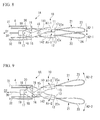
- FIGS. 8 and 9 are cross-sectional view showing an internal structure of the treatment portion 10.
- FIG. 8 shows a state in which the jaws 11 and 12 are substantially closed.
- FIG. 9 shows a state in which the jaws 11 and 12 are opened.
- the pair of jaws 11 and 12 have arms 141 and 142 integrally extending from the jaws 11 and 12 at proximal end sides thereof.
- the arm 141 integrally formed with the first jaw 11 and the arm 142 integrally formed with the second jaw 12 cross in an X shape at an intermediate portion between the distal end and the proximal end that connect the jaws 11 and 12.
- a fixing pin 15 is installed at a place at which the arm 141 and the arm 142 cross in an X shape.
- the fixing pin 15 is fixed to the cylindrical housing 4 fixed to the distal end of the longitudinal member 3.
- Each of the arms 141 and 142 is rotatably supported by the fixing pin 15.
- one end of an intermediate link 18 is rotatably connected to a proximal end of each of the arms 141 and 142 by a pin 16.
- the other ends of the two intermediate links 18 are rotatably connected to a manipulation block 19 by a pin 17.
- a distal end of an open-close manipulation wire 30 is connected to the manipulation block 19.
- an open-close mechanism 20 of the jaws 11 and 12 is constituted by a four-joint link. That is, the pair of jaws 11 and 12 are configured to be opened and closed as the manipulation block 19 advances and retreats along the longitudinal axis of the longitudinal member 3.
- the tie point 23x of the starting end and the terminating end of the loop wire 23 protrudes from the distal end opening 13 of the jaws 11 and 12, the tie point 23x may not exit the distal end opening 13 of the jaws 11 and 12.
- a plane in which the loop of the loop wire 23 is formed crosses an open-close direction (the arrow A2 direction) of the loop wire 23.
- the loop wire 23 is contracted at the maximum position, the loop wire 23 is provided so as to be capable of being accommodated in the distal end opening 13 of the jaws 11 and 12.
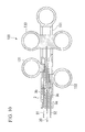
- FIG. 10 is a cross-sectional view showing an internal structure of the operating portion of the treatment device according to the embodiment.
- the operating portion 100 of the treatment device 1A has an operating portion main body 101, and three manipulation members, i.e., an open-close manipulation member 130, a first advance-retreat manipulation member 131, and a second advance-retreat manipulation member 132.
- the three manipulation members 130, 131 and 132 are slidably installed at the operating portion main body 101.
- a proximal end of the longitudinal member 3 is connected to the operating portion main body 101.
- a first lumen 3a through which the open-close manipulation wire 30 is inserted, and two lumens, i.e., a second lumen 3b and a third lumen 3c through which the advance-retreat manipulation wires 31 and 32 are inserted, respectively, are installed at the longitudinal member 3.
- the three lumens 3a, 3b and 3c are disposed at places positioned at peaks of a triangular shape formed in a circular cross-section perpendicular to the longitudinal axis of the longitudinal member 3.
- the proximal end of the open-close manipulation wire 30 is connected to the open-close manipulation member 130.
- the proximal ends of the advance-retreat manipulation wires 31 and 32 are connected to the first advance-retreat manipulation member 131 and the second advance-retreat manipulation member 132, respectively.
- an operator can open and close the jaws 11 and 12 via the manipulation wire 30 through a slide manipulation of the open-close manipulation member 130.
- the operator can independently advance and retreat the loop wire 23 of the grasping members 21 and 22 and expand and contract the loop wire 23 via the manipulation wires 31 and 32 through a slide manipulation of the first advance-retreat manipulation member 131 and the second advance-retreat manipulation member 132.
- An action of the treatment device 1A according to the embodiment will be described as an example of a procedure using the treatment device 1A.
- FIG. 11 is a flowchart showing a process of the procedure using the treatment device 1A according to the embodiment.
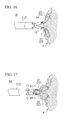
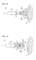
- FIGS. 12 to 19 are views showing a process of the procedure.
- the procedure exemplified in the embodiment is a procedure referred to as a pancreatic necrosectomy.
- a pancreatic necrosectomy is a procedure of removing necrotic pancreatic tissue from the pancreas by taking the tissue into the alimentary canal or to the outside of the body.
- the endoscope apparatus 500, an endoscope puncture needle 510, an endoscope expansion catheter 520, and the treatment device 1 A according to the embodiment are used.
- the treatment device 1 A Before starting the procedure, the treatment device 1 A is held in a state in which the jaws 11 and 12 are closed. In addition, the grasping members 21 and 22 are reduced to a minimum size. When the loop wire 23 that constitutes the grasping members 21 and 22 can be received in the jaws 11 and 12, the loop wire 23 is received in the jaws 11 and 12. That is, before starting the procedure, the manipulation members 130, 131 and 132 shown in FIG. 6 are pulled toward the proximal end side.
- the insertion portion 501 of the endoscope apparatus 500 is inserted into the stomach of a patient (step S 1 shown in FIG. 11 ).
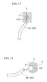
- step S1 as shown in FIG. 12 , the distal end of the insertion portion 501 of the endoscope apparatus 500 passes through the esophagus from the mouth to be disposed in the stomach G.
- step S1 as the operator observes the inside of the stomach using an endoscope image, an area appropriate for incision is selected.
- step S1 is terminated, and step S2 is performed.
- Step S2 is a step of incising a rear wall of the stomach and forming a passage configured to guide the treatment device 1A into the pancreas at the stomach and the pancreas.
- step S2 in order to incise the area selected in step S1, the above-mentioned endoscope puncture needle 510 is attached to the treatment device channel 502 of the endoscope apparatus 500.
- the operator opens a hole at the rear wall of the stomach using an endoscope high frequency knife 510, and forms an opening portion X (see FIG. 13 ).
- step S2 is terminated, and step S3 is performed.
- Step S3 is a step of expanding the passage (the opening portion X) formed in the step S2.
- a guide wire is introduced into the body through an inner tube (not shown) formed in the endoscope high frequency knife 510. Further, the endoscope expansion catheter 520 is introduced into the body along the guide wire. The distal end of the endoscope expansion catheter 520 is guided to the opening portion X formed in the stomach by the guide wire. As the endoscope expansion catheter 520 is guided to the opening portion X, a balloon portion of the endoscope expansion catheter 520 is inserted into the opening portion X formed in step S2.
- the balloon portion is expanded to expand the opening portion X to a desired size as shown in FIG. 14 . Accordingly, in step S3, the passage expanded to a size such that the treatment portion 10 can be inserted into the pancreas from the inside of the stomach is formed at the stomach and the pancreas.
- a high frequency treatment device configured to incise the tissue using high frequency current is used.
- step S3 is terminated, and step S4 is performed.
- Step S4 is a step of guiding the treatment portion 10 into the pancreas through the passage expanded in step S3.
- step S4 the treatment device 1A is attached to the endoscope channel 502 of the endoscope apparatus 500 (see FIG. 1 ).
- the endoscope puncture needle or the endoscope expansion catheter may be removed from the endoscope channel, and the treatment device 1 A may be attached to the endoscope channel using the guide wire that becomes usable thereby.
- the treatment portion 10 and the insertion portion 2 are inserted into the endoscope channel 502. Then, the distal end of the longitudinal member 3 of the treatment device 1A protrudes from the distal end of the endoscope channel 502.
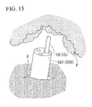
- the operator who manipulates the endoscope apparatus 500 to which the treatment device 1A is attached guides the distal end of the longitudinal member 3 into the pancreas through the inside of the opening portion X formed at the stomach and the pancreas through a curve manipulation or by moving the insertion portion 501 of the endoscope apparatus 500 (see FIG. 15 ).
- the guide wire is removed.
- step S4 is terminated, and step S5 is performed.
- Step S5 is a step of collecting the necrotic tissue using the treatment portion 10 guided into the pancreas in step S4.
- step S5 the operator observes the image obtained by the endoscope apparatus 500 and adjusts the position of the treatment portion 10.
- the operator moves the distal end of the endoscope apparatus 500 toward a tissue P in which the necrotic tissue is present as a collecting target.
- the open-close manipulation member 130 and the advance-retreat manipulation members 131 and 132 are moved to the distal end side.
- the pair of jaws 11 and 12 are opened, and the pair of grasping members 21 and 22 are widened.
- the operator closes the pair of jaws 11 and 12 as shown in FIG. 17 while pressing the curved portions of the distal ends of the loop wires 23 of the grasping members 21 and 22 against the tissue P.
- the pair of jaws 11 and 12 may be completely closed or may not be completely closed. That is, the jaws 11 and 12 may be moved such that the loop wire 23 installed at the first jaw 11 and the loop wire 23 installed at the second jaw 12 approach each other.
- the necrotic tissue T is sandwiched by the loop wires 23 of the grasping members 21 and 22.
- the operator pulls the insertion portion 2 in an arrow C direction.
- the operator closes the pair of jaws 11 and 12 by pulling the insertion portion 2 in the arrow C direction and closes the pair of grasping members 21 and 22.
- the necrotic tissue T is caught in the loop wires 23 of the pair of grasping members 21 and 22 and separated from the tissue P.
- the necrotic tissue T in the pancreas is caught in the loop wire 23 and separated from the normal tissue P.
- the necrotic tissue T grasped by the pair of grasping members 21 and 22 is collected by the treatment device 1A while being sandwiched between the pair of grasping members 21 and 22.
- the pair of grasping members 21 and 22 configured to be opened and closed in a direction crossing the longitudinal axis of the longitudinal member 3 include the loop wire 23 curved in an annular shape within a plane crossing the open-close direction of the jaws 11 and 12. Accordingly, by pinching a large amount of the necrotic tissue T by the loop wires 23 in a state that the loop wires 23 of the pair of grasping members s 21 and 22 are opened, a portion of the necrotic tissue T can be captured in the loop of the loop wire 23 with the pinching force. That is, as the grasping force is applied from the loop wire 23 to the necrotic tissue T, the necrotic tissue T is pushed into the loop.
- step S5 is terminated, and step S6 is performed.
- Step S6 is a step of moving the necrotic tissue collected in step S5 to the outside of the pancreas.
- step S6 is terminated, and step S7 is performed.
- Step S7 is a step of discarding the necrotic tissue in the stomach.
- step S7 first, the operator opens the jaws 11 and 12. In addition, the operator enlarges the loops of the loop wires 23 of the grasping members 21 and 22. As a result, the necrotic tissue T grasped by the loop wires 23 of the grasping members 21 and 22 is separated from the loop wire 23 to be thrown away in the stomach.
- the operator individually enlarges or reduces the loop wires 23 of the first grasping member 21 and the second grasping member 22. Accordingly, removal of the necrotic tissue T is promoted.
- step S7 the treatment portion 10 in which the necrotic tissue is accommodated may be discharged to the outside of the body according to necessity. In this case, the entire treatment device 1A may be discharged to the outside of the body with the endoscope apparatus 500.
- the treatment portion 10 in which the necrotic tissue T is accommodated may be drawn to the outside of the body through the endoscope channel 502. The necrotic tissue drawn to the outside of the body may be used for pathologic examination.
- step S7 is terminated.
- steps from step S4 to step S7 can be repeated a plurality of times.
- the pair of grasping members 21 and 22 are installed at the jaws 11 and 12 to be opened and closed in the direction crossing the longitudinal axis of the longitudinal member 3. Accordingly, the grasping members 21 and 22 can be freely opened and closed with respect to the size of the tissue to be removed. In a state in which the jaws 11 and 12 are largely opened, much tissue can be collected when the loop wire 23 is closed with the jaws 11 and 12 in the next step.
- the tissue when the tissue is grasped by the grasping members having a small grasping area, a small amount of the tissue may be torn off.
- the grasping members 21 and 22 are constituted by the loop wires 23 curved in an annular shape, since a substantial grasping surface is largely widened, a large range of tissue is collected.
- the tissue is grasped at a substantially large area, since the grasping force is distributed, a large amount of the tissue is collected without breaking off.
- the grasping members 21 and 22 include the loop wire 23 bent in an annular shape within a plane crossing the open-close direction of the jaws 11 and 12. Accordingly, as the large amount of necrotic tissue T is pinched in a state in which the loop wires 23 of the pair of grasping members 21 and 22 are opened, some of the necrotic tissue T can be captured at the inside of the loops of the loop wires 23 with the pinching force. That is, as the grasping force is applied from the loop wires 23 to the necrotic tissue T, the necrotic tissue T is pressed into the loop. For this reason, in this state, as the operator pulls the longitudinal member 3 toward the operator's body, the necrotic tissue T can be caught in the loop wire 23 to be securely collected.
- the grasping members 21 and 22 are constituted by the loop wires 23 having flexibility, the grasping force can be smoothly applied to the tissue, and the necrotic tissue can be smoothly collected without applying an excessive force. Since the loop wire 23 has a shape closed in a loop shape, the loop wire 23 is not needlessly deformed with a reaction force received from the tissue. In addition, as the grasping members 21 and 22 are constituted by the loop wires 23, since the portion abutting the tissue becomes a curved wire portion, damage to the tissue such as bleeding or the like can be prevented.
- the substantial grasping area of the first grasping member 21 and the second grasping member 22 can be varied. Accordingly, the size of the treatment portion 10 of the treatment device 1 A can be varied according to the size of the necrotic tissue of the collecting target. Since the loop wires 23 that constitute the grasping members 21 and 22 are installed to freely advance and retreat with respect to the jaws 11 and 12, the loop wire 23 can be contracted to be small upon insertion into the human body, and opened to be large upon collection of the tissue.
- the loop wires 23 of the grasping members 21 and 22 can independently advance and retreat and be enlarged or reduced, and the collected tissue can be easily removed from the grasping members 21 and 22.
- the treatment device 1A can contract the loop wire 23 of the second grasping member in a state in which the loop wire 23 of the first grasping member 21 is widened, or can be manipulated in a reverse manner. Accordingly, according to the treatment device 1A of the embodiment, as the above-mentioned enlarging or reducing operation is repeated at each of the grasping members 21 and 22, even when the collected tissue is caught in the wire, the collected tissue can be easily removed.
- the loop wire 23 of the first grasping member 21 and the loop wire 23 of the second grasping member 22 are configured to individually advance and retreat and be freely enlarged or reduced.
- the loop wires 23 of both of the grasping members 21 and 22 may be configured to advance and retreat and be freely enlarged or reduced simultaneously and integrally rather than individually.
- the advance-retreat manipulation wires 31 and 32 are integrated as one wire.
- the treatment device 1 A can obtain a good collecting effect.
- FIG. 20 is a perspective view showing a configuration of a treatment device 1A-1 of the first modified example.
- FIG. 21 is a side view showing the configuration of the treatment device 1A-1 of the first modified example.
- a convex portion 23a is formed at the distal end of the loop wire 23 that constitutes each of the grasping members 21 and 22.
- the distal end of the loop wire 23 is the distal point 23n maximally spaced apart from the jaws 11 and 12.
- the convex portion 23a is formed to protrude at a grasping side with respect to the object to be grasped, i.e., a side opposite to the pair of grasping members 21 and 22. In this way, as the convex portion 23a is formed at the distal end of the loop wire 23, the collecting target tissue is likely to be hooked by the convex portion 23a.
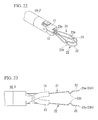
- FIG. 22 is a perspective view showing a configuration of a treatment device 1A-2 of the second modified example.
- FIG. 23 is a side view showing the configuration of the treatment device 1A-2 of the second modified example.
- convex portions 23b are formed at the middle between the distal end and the proximal end of the loop wire 23 that constitutes each of the grasping members 21 and 22.
- the proximal end of the loop wire 23 is a proximal point 23m closest to the jaws 11 and 12. Accordingly, the middle between the distal end and the proximal end of the loop wire 23 is the middle between the distal point 23n and the proximal point 23m of the loop wire 23.
- the convex portion 23b is formed to protrude in a wave form at a grasp side with respect to the object to be grasped, i.e., a side opposite to the pair of grasping members 21 and 22, when seen from a side view. In this way, as the convex portion 23b is formed at the distal end of the loop wire 23, the collected tissue is likely to be hooked by the convex portion 23b.
- the convex portions 23b may be disposed at deviated positions, in addition to the case in which they are formed at the same position of the first grasping member 21 and the second grasping member 22.
- FIG. 24 is a perspective view showing a configuration of a treatment device 1A-3 of the third modified example.
- FIG. 25 is a side view showing a configuration of the treatment device 1A-3 of the third modified example.
- a plurality of convex portions 23a and 23b are formed at the distal end of the loop wire 23 that constitutes each of the grasping members 21 and 22, and the middle between the distal end and the proximal end of the loop wire 23. That is, the modified example corresponds to the case in which the first modified example and the second modified example are combined, and further, the plurality of convex portions 23b of the second modified example are formed. In this way, as the plurality of convex portions 23a and 23b are formed, and the collected tissue is more likely to be hooked by the convex portions 23a and 23b.
- the convex portions 23b may be disposed at deviated positions, in addition to the case in which they are formed at the same position of the first grasping member 21 and the second grasping member 22.
- FIG. 26 is a perspective view showing a configuration of a treatment device 1A-4 of the fourth modified example.
- a net 24 stretched on a surface surrounding the loop wire 23 is installed at the loop wires 23 that constitute each of the grasping members 21 and 22.
- a thread-like material that can be used in the body such as a suture or the like used for surgery, specifically, a thread formed of a resin such as nylon, rubber, or the like, silk, or cotton
- the net 24 may be formed of a metal wire having biocompatibility generally used for the treatment device, specifically, a single wire or a stranded wire formed of stainless steel or a super-elastic alloy (NiTi alloy or the like).
- a size of a mesh of the net 24 may be appropriately set according to the state of the treatment target area. In this way, as the net 24 is stretched by the loop wire 23, dropping of the collected tissue is prevented.
- the net 24 may be stretched by the loop wire 23 of any one of the grasping members.
- FIG. 27 is a perspective view showing a configuration of the fifth modified example.
- the pair of grasping members 21 and 22 are constituted by wires 25 curved in a spiral shape.
- a spiral of the wire 25 may be formed in a two-dimensional shape, or may be formed in a three-dimensional shape having swelling in a direction perpendicular to the open-close direction of the grasping members 21 and 22.
- the wires 25 curved in a spiral shape are formed of a shape memory alloy, the wires 25 are formed in a spiral shape while protruding from the jaws 11 and 12. The wires 25 are installed to advance and retreat with respect to the jaws 11 and 12.
- the wires 25 are pushed in arrow B1-1 and B2-1 directions shown in FIG. 27 , the wires 25 are deformed in a spiral shape with expansion.
- the wires 25 are drawn in the arrow B1-2 and B2-2 directions shown in FIG. 27 , the wires 25 are received in the jaws 11 and 12. Even in this case, the wire 25 of the first grasping member 21 and the wire 25 of the second grasping member 22 are installed to advance and retreat individually.
- the grasping members 21 and 22 are constituted by the spiral wires 25, like in the fourth modified example, an effect similar to the case in which the collected tissue is held by the net 24 not to be dropped is exhibited.
- the spiral wire 25 can come in contact with the tissue with a small force more softly than that of the loop wire 23.
- both of the pair of grasping members 21 and 22 are constituted by the spiral wires.
- only one of the grasping members may be constituted by the spiral wire, and the other grasping member may be constituted by, for example, the above-mentioned loop wire 23 shown in FIG. 2 .
- a ratchet (not shown) configured to move the open-close manipulation wire 30 at a certain pitch is installed at the operating portion 100.
- the ratchet of the modified example is a ratchet configured with a pitch defined by engaging protrusions, like a ratchet installed at a Pean forceps.
- the pitch defined in the ratchet is set such that, for example, a degree of open-close of the pair of jaws is switched 3 to 5 steps between a complete closing state and a complete opening state of the pair of jaws 11 and 12. Accordingly, in the modified example, the position of the open-close manipulation wire 30 can be fixed with respect to the operating portion 100 using the ratchet.
- an opening angle of the pair of jaws 11 and 12 can be finely adjusted or the positions of the jaws 11 and 12 can be fixed.
- a grasping capability can be easily adjusted according to hardness, viscosity, or the like, of the tissue serving as a grasping target.
- the ratchet according to the same principle as the modified example may be installed at the operating portion 100 in order to move the advance-retreat manipulation wires 31 and 32 at a certain pitch.
- the size of the loop is finely adjusted by the loop wire 23, and the loop can be easily maintained at the finely adjusted size.
- FIG. 28 is a view showing a configuration of a treatment portion of the distal end of the treatment device of the second embodiment of the present invention.
- a first grasping member 41 and a second grasping member 42 are constituted by a set of a plurality of grasping members which are positioned at an outward of the grasping members and an inward of the grasping members, respectively.
- the grasping members positioned at the outward thereof are main grasping members 411 and 421.
- the grasping members positioned at the inward of the grasping members are auxiliary grasping members 412 and 422.
- the main grasping members 411 and 421 positioned at the outward of the grasping members correspond to the grasping members 21 and 22 of the first embodiment.
- the auxiliary grasping members 412 and 422 positioned at the inward of the grasping members in an expanded state are formed to be smaller than the main grasping members 411 and 421 positioned at the outward of the grasping members.
- the main grasping members 411 and 421 positioned at the outward of the grasping members and the auxiliary grasping members 412 and 422 positioned at the inward of the grasping members are also constituted by the loop wires 23 and 26 curved in a loop shape.
- a size of a loop of an auxiliary loop wire (an auxiliary wire) 26 is formed to be smaller than that of a loop of a main loop wire (a main wire) 23.
- the auxiliary loop wire 26 is disposed to have an interval inside the main loop wire 23 positioned at the outward of the grasping members.
- the main loop wire 23 and the auxiliary loop wire 26 are connected to the distal ends of the advance-retreat manipulation wires 31 and 32 by joining the starting ends and the terminating ends of the wires 23 and 26. Accordingly, the main loop wire 23 and the auxiliary loop wire 26 advance and retreat with an advance-retreat manipulation of the advance-retreat manipulation wires 31 and 32 to enlarge or reduce the size of the loop.
- each of the first grasping member 41 and the second grasping member 42 is constituted by a set of the main loop wire 23 and the auxiliary loop wire 26, when the tissue is collected, a tangled portion of the grasping members 41 and 42 and the tissue is increased. According to the embodiment, the tissue can be more securely collected. In addition, according to the embodiment, the collected tissue held once is hard to lose. The other effects are the same as those of the first embodiment.
- a configuration in which only the auxiliary loop wire 26 cannot freely advance and retreat and cannot be freely enlarged or reduced may be provided.
- a configuration in which only the main loop wire 23 cannot freely advance and retreat and cannot be freely enlarged or reduced may be provided.
- the number of auxiliary grasping members may be set to 2 or more.
- any one of the grasping members 41 and 42 may be constituted by only the main grasping member without the auxiliary grasping member.
- FIG. 29 is a perspective view showing a configuration of the first modified example.
- the size of the loop of the auxiliary loop wire 26 of one grasping member 41 is different from the size of the loop of the auxiliary loop wire 26 of the other grasping member 42.
- the size of the loop of the auxiliary loop wire 26 is not varied. In this way, when the size of the loop of the auxiliary loop wire 26 is different at the one grasping member 41 and the other grasping member 42, the large side and the small side of the loop can be discriminated according to the size of the collected tissue.
- FIGS. 30 to 33 While a schematic configuration of only one grasping member of the first grasping member 41 and the second grasping member 42 supported by the jaws 11 and 12 is shown, the other grasping member also has the same configuration. Alternatively, a combination of the other grasping member is not particularly limited as long as only the main loop wire 23 or the main loop wire 23 and the auxiliary loop wire 26 are provided.
- FIG. 30 is a perspective view schematically showing a grasping member of a second modified example of the second embodiment.
- a straight line connecting the proximal point 23m supported by a jaw of the main loop wire 23 and the distal point 23n maximally spaced apart from the jaw is defined as a centerline 23h of the main loop wire 23.
- a straight line connecting a proximal point 26m supported by a jaw of the auxiliary loop wire 26 and a distal point 26n maximally spaced apart from the jaw is defined as a centerline 26h of the auxiliary loop wire 26.
- the centerline 23h of the main loop wire 23 and the centerline 26h of the auxiliary loop wire 26 overlap in the same plane H including both of the main loop wire 23 and the auxiliary loop wire 26.
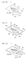
- FIG. 31 is a perspective view schematically showing one grasping member of a third modified example of the second embodiment.
- the plane H 1 including the main loop wire 23 and the plane H2 including the auxiliary loop wire 26 have a relation in which they are parallel to each other with an interval therebetween.
- the centerline 23h of the main loop wire 23 and the centerline 26h of the auxiliary loop wire 26 are formed at a position overlapping when seen in a direction perpendicular to both of the planes H1 and H2.
- FIG. 32 is a perspective view schematically showing one grasping member of a fourth modified example of the second embodiment.
- the plane H1 including the main loop wire 23 and the plane H2 including the auxiliary loop wire 26 have a relation in which they form an inclined angle ⁇ 1.
- the centerline 23h of the main loop wire 23 and the centerline 26h of the auxiliary loop wire 26 are formed at a position overlapping when seen in a direction perpendicular to the plane H1 including the main loop wire 23.
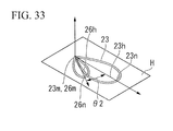
- FIG. 33 is a perspective view schematically showing one grasping member of a fifth modified example of the second embodiment.
- the centerline 23h of the main loop wire 23 and the centerline 26h of the auxiliary loop wire 26 are deviated by an angle ⁇ 2 only when seen in a direction perpendicular to the plane H including the main loop wire 23.
- the same effect as the above-mentioned embodiment is exhibited.
- FIG. 34 is a perspective view schematically showing a sixth modified example of the second embodiment.
- FIG. 34 is a perspective view schematically showing a relation between a pair of auxiliary grasping members (auxiliary loop wires) of the modified example.
- FIG. 35 is a perspective view schematically showing a relation between the pair of auxiliary grasping members (auxiliary loop wires) of the modified example.
- a convex portion 26a protruding at a grasp side with respect to the object to be grasped is installed at at least one of the auxiliary loop wires 26 that constitute the respective grasping members 41 and 42.
- a position of the convex portion 26a is not limited as long as the position is on the auxiliary loop wire 26.
- a height of the convex portion 26a on the auxiliary loop wire 26 may be a height at which the pair of grasping members 41 and 42 overlap the convex portions 26a of opposite sides when the pair of grasping members 41 and 42 are closed.
- the height of the convex portion 26a on the auxiliary loop wire 26 may be a height at which the pair of grasping members 41 and 42 approach the convex portions 26a of the opposite sides when the pair of grasping members 41 and 42 are closed.
- FIG. 37 is a perspective view schematically showing a seventh modified example of the second embodiment.
- the main loop wire 23 and the auxiliary loop wire 26 of the grasping members 41 and 42 are set to incline to further inside than the jaws 11 and 12.
- the auxiliary loop wire 26 is omitted, the same example is presented. That is, in the grasping member of this example in which only the main loop wire 23 is installed, when the pair of grasping members are closed, the main loop wire is set to incline to a position further inside than the position of the jaw.
- FIG. 38 is a perspective view schematically showing an eighth modified example of the second embodiment.
- the main loop wire 23 and the auxiliary loop wire 26 of the grasping members 41 and 42 are configured to enter the loops of the opposite sides. That is, the main loop wire 23 and the auxiliary wire 26 of the first grasping member 41 enter the loops of the main loop wire 23 and the auxiliary loop wire 26 of the second grasping member 42. Alternatively, the main loop wire 23 of the first grasping member 41 enters the loop of the main loop wire 23 of the second grasping member 42. Alternatively, the auxiliary loop wire 26 of the first grasping member 41 is configured to enter the loop of the auxiliary loop wire 26 of the second grasping member 42.
- auxiliary loop wire 26 is omitted, the same example may be presented. That is, there is an example in which, when the grasping member having only the main loop wire 23 is closed, the main loop wire of the first grasping member 41 is set to enter the loop of the main loop wire of the second grasping member 42.
- FIG. 39 is a perspective view showing a schematic configuration of the third embodiment of the present invention.
- the first grasping member 21 is constituted by the loop wire 23.
- the second grasping member 22 is constituted by the plate-shaped member 27 having a grasping surface 27a crossing the open-close direction of the pair of jaws 11 and 12.
- a plate-shaped member 27 is a member such as a lancet.
- FIG. 40 is a perspective view showing a schematic configuration of the fourth embodiment of the present invention.
- the plate-shaped member 27 having the grasping surface 27a crossing the open-close direction of the pair of jaws 11 and 12 is used.
- FIG. 41 is a perspective view showing a schematic configuration of the treatment device 1E according to the fifth embodiment of the present invention.
- the treatment device 1E according to the embodiment two or more of the auxiliary wires 26 of the second embodiment are installed.
- the number of auxiliary wires 26 may be any number.
- FIGS. 42 and 43 are views showing a configuration of a treatment portion of a distal end of the treatment device 1F of the sixth embodiment.
- FIG. 42 is a perspective view showing a state in which a pair of jaws are closed.
- FIG. 43 is a perspective view showing a state in which the pair of jaws are opened.
- a treatment portion 50 of the treatment device 1F of the embodiment has a pair of jaws 51 and 52 having a semi-circular columnar shape so as to form a circular columnar body when the two jaws contact with each other.
- Through-holes 54 and 55 passing through to the proximal end surfaces of the jaws 51 and 52 are formed in distal end surfaces 53 of the jaws 51 and 52.
- the pair of grasping members 56 and 57 are constituted by sets of two kinds of grasping members which are positioned at an outward of the grasping members and an inward of the grasping members.
- the grasping members positioned at the outward thereof are main grasping members 561 and 571.
- the grasping members positioned at the inward thereof are auxiliary grasping members 562 and 572.
- the auxiliary grasping members 562 and 572 positioned at the inward of the grasping members in an enlarged state are formed to be smaller than the main grasping members 561 and 571 positioned at the outward of the grasping members.
- Each of the main grasping members 561 and 571 positioned at the outward of the grasping members and the auxiliary grasping members 562 and 572 positioned at the inward of the grasping members is constituted by half loop wires 23 and 26 curved in a half loop shape.
- a size of a half loop of an auxiliary half loop wire (an auxiliary wire) 26 in which the size of the half loop is formed to be small is formed to be smaller than a half loop of a main half loop wire (a main wire) 23.
- the auxiliary half loop wire 26 is disposed to be spaced apart from an inner side of the main half loop wire 23 positioned at the outward of the grasping members.
- the main half loop wire 23 and the auxiliary half loop wire 26 are formed such that both ends of the wires 23 and 26 curved in half loop shapes are inserted into the through-holes 54 and 55 formed at the distal end surfaces of the jaws 51 and 52 to extend at the same longitudinal member (not shown) as the longitudinal member 3 shown in FIG. 2 .
- the main half loop wire 23 and the auxiliary half loop wire 26 are installed to freely advance in a direction protruding from the jaws 51 and 52 and retreat in a direction accommodated in the jaws 51 and 52.
- the half loop wires 23 and 26 are installed at the pair of jaws 51 and 52 to independently and freely advance and retreat. Accordingly, the half loop wires 23 and 26 are configured to independently and freely enlarge or reduce the size of the half loop within the plane crossing the open-close direction of the jaws 51 and 52 according to the advance and retreat operation of the half loop wires 23 and 26.
- the same effect as the treatment device 1B of the second embodiment is exhibited.
- FIGS. 44 and 45 are views showing a configuration of a treatment portion 60 of a distal end of the treatment device 1G of the seventh embodiment.
- FIG. 44 is a perspective view showing a state in which a pair of jaws are closed.
- FIG. 45 is a perspective view showing a state in which the pair of jaws are opened.
- a combination of main grasping members 661 and 671 and auxiliary grasping members 662 and 672 of a first grasping member 66 and a second grasping member 67 supported by a first jaw 51 and a second jaw 52 is different from the sixth embodiment. That is, while the main grasping members 661 and 671 are constituted by the same loop wires 23 as in the sixth embodiment, the auxiliary grasping members 662 and 672 are constituted by the plate-shaped members 27 directly protruding from the distal end surfaces of the jaws 51 and 52.
- auxiliary grasping members 662 and 672 are constituted by the plate-shaped members 27, a large tissue is grasped by the loop wires 23 of the main grasping members 661 and 671 positioned at the outward of the grasping members, and a small tissue is grasped by the plate-shaped members 27 of the auxiliary grasping members 662 and 672 positioned at the inward of the grasping members.
- the other effects are the same as those of the sixth embodiment.
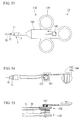
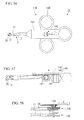
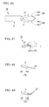
- FIG 46 is a plan view of the treatment device 1H according to the embodiment.
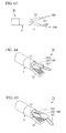
- FIG. 47 is a perspective view of a distal end structure of the treatment device 1H according to the embodiment.
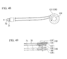
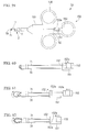
- FIG. 48 is a plan view showing a configuration of a pulley group of the treatment device 1H according to the embodiment.
- FIG. 49 is a side view showing a configuration of the pulley group of the treatment device 1H according to the embodiment.
- the treatment device 1H has a main loop wire 70 and an auxiliary loop wire 71 having different configurations from the main loop wire 23 and the auxiliary loop wire 26, instead of the main loop wire 23 and the auxiliary loop wire 26 described in the second embodiment.
- the treatment device 1H has an operating portion 110 having a different configuration from the operating portion 100, instead of the operating portion 100 described in the first embodiment.
- the main loop wires 70 are installed at each of the first jaw 11 and the second jaw 12.
- a first end of the main loop wire 70 installed at the jaw 11 is fixed to a portion of the distal end of the jaw 11.
- a second end of the main loop wire 70 installed at the jaw 11 is connected to the operating portion 110.
- the first end of the main loop wire 70 installed at the jaw 11 enters the through-hole 11b into which the auxiliary loop wire 71 is inserted to freely advance and retreat, and the first end of the main loop wire 70 is fixed to the jaw 11 in the through-hole 11b.
- the first end of the main loop wire 70 installed at the jaw 12 is fixed to a portion of the distal end of the jaw 12.
- the second end of the main loop wire 70 installed at the jaw 12 is connected to the operating portion 110.
- the first end of the main loop wire 70 installed at the jaw 12 enters the through-hole 12b into which the auxiliary loop wire 71 is inserted to freely advance and retreat, and the first end of the main loop wire 70 is fixed to the jaw 12 in the through-hole 12b.
- the auxiliary loop wires 71 are installed at each of the jaw 11 and the jaw 12.
- a first end of the auxiliary loop wire 71 installed at the jaw 11 is fixed to a portion of the distal end of the jaw 11.
- a second end of the auxiliary loop wire 71 installed at the jaw 11 is connected to the operating portion 110.
- the first end of the auxiliary loop wire 71 installed at the jaw 11 enters a through-hole 11a into which the main loop wire 70 is inserted to freely advance and retreat, and the first end of the auxiliary loop wire 71 is fixed to the jaw 11 in the through-hole 11a.
- the first end of the auxiliary loop wire 71 installed at the jaw 12 is fixed to a portion of the distal end of the jaw 12.
- the second end of the auxiliary loop wire 71 installed at the jaw 12 is connected to the operating portion 110.
- the first end of the auxiliary loop wire 71 installed at the jaw 12 enters a through-hole 12a into which the main loop wire 70 is inserted to freely advance and retreat, and the first end of the auxiliary loop wire 71 is fixed to the jaw 11 in the through-hole 12a.
- the operating portion 110 shown in FIG. 46 has a manipulation knob 133 instead of the manipulation members 131 and 132 with respect to the operating portion main body 101 described in the first embodiment.
- the manipulation knob 133 is a substantially columnar member attached to the operating portion main body 101 such that a rotational center extends in a direction perpendicular to the longitudinal axis of the operating portion main body 101.
- a dial 134 is installed at a portion of the operating portion main body 101 exposed to the outside.
- the dial 134 is configured such that the operator can touch the dial 134 to rotate the manipulation knob 133.
- a rotary shaft 135 and a pulley group 136 are installed at a portion of the manipulation knob 133 disposed inside the operating portion main body 101.
- the rotary shaft 135 is fixed to the dial 134 or integrally formed with the dial 134.
- the pulley group 136 is fixed to the rotary shaft 135 such that a rotational axis of the rotary shaft 135 serves as a rotational center.
- Large diameter pulleys (first movable members) 137 and 139 and small diameter pulleys (second movable members) 138 and 140 are installed at the pulley group 136.
- the main loop wire 70 is suspended on outer circumferences of the large diameter pulleys 137 and 139.
- the auxiliary loop wire 71 is suspended on outer circumferences of the small diameter pulleys 138 and 140.
- the large diameter pulley 137 is a pulley having a radius larger than that of the small diameter pulley 138.
- the large diameter pulley 139 is a pulley having a radius larger than that of the small diameter pulley 140.
- the radiuses of the two large diameter pulleys 137 and 139 are equal to each other, and the radiuses of the two small diameter pulleys 138 and 140 are equal to each other.
- the second end of the main loop wire 70 installed at the first jaw 11 is fixed to the first large diameter pulley 137 of the two large diameter pulleys 137 and 138.
- the second end of the main loop wire 70 installed at the jaw 12 is fixed to the second large diameter pulley 139.
- the direction in which the main loop wire 70 is wound on the first large diameter pulley 137 is the same as the direction in which the main loop wire 70 is wound on the second large diameter pulley 139.
- the second end of the auxiliary loop wire 71 installed at the first jaw 11 is fixed to the first small diameter pulley 138 of the two small diameter pulleys 138 and 140.
- the second end of the auxiliary loop wire 71 installed at the jaw 12 is fixed to the second small diameter pulley 140.
- the direction in which the auxiliary loop wire 71 is wound on the first small diameter pulley 138 is the same as the direction in which the auxiliary loop wire 71 is wound on the second small diameter pulley 140.
- the direction in which the main loop wire 70 is wound on the first large diameter pulley 137, the direction in which the main loop wire 70 is wound on the second large diameter pulley 139, the direction in which the auxiliary loop wire 71 is wound on the first small diameter pulley 138 and the direction in which the auxiliary loop wire 71 is wound on the second small diameter pulley 140 are all the same. Further, the large diameter pulleys 137 and 139 and the small diameter pulleys 138 and 140 are integrally rotated with the rotary shaft 135 when the rotary shaft 135 is rotated about the rotational axis thereof as a rotational center.
- the pulley group 136 moves the two main loop wires 70 and the two auxiliary loop wires 71 to advance and retreat such that the sizes of the entire loops protruding from the jaws 11 and 12 become larger or the sizes of the entire loops protruding from the jaws 11 and 12 become smaller.
- FIG. 50 is a view showing the action of the treatment device 1H according to the embodiment.
- FIG. 51 is a plan view showing an action of the pulley group of the treatment device according to the embodiment.
- FIG. 52 is a side view showing the action of the pulley group of the treatment device of the embodiment.
- a protrusion length from the jaws 11 and 12 of the main loop wire 70 attached to the large diameter pulleys 137 and 139 is larger than a protrusion length from the jaws 11 and 12 of the auxiliary loop wire 71 attached to the small diameter pulleys 138 and 140.
- the protrusion length of the main loop wire 70 from the jaw 11 and the protrusion length of the main loop wire 70 from the jaw 12 are equal to each other.
- the protrusion length of the auxiliary loop wire 71 from the jaw 11 and the protrusion length of the auxiliary loop wire 71 from the jaw 12 are equal to each other.
- a loop shape having the best operational efficiency can be selected to correspond to characteristics of the tissue serving as the collecting target.
- FIG. 53 is a plan view showing a treatment device of the modified example.
- FIG. 54 is a schematic plan view showing a configuration of a pinion, a rack and a slider of the treatment device of the modified example.
- FIG. 55 is a schematic side view showing the configuration of the pinion, the rack and the slider of the treatment device of the modified example.
- FIGS. 56 to 58 are views showing an action of the treatment device of the modified example.
- a treatment device 1I of the modified example includes a pinion 141 fixed to the rotary shaft 135 and a slider 144, instead of the manipulation knob 133 described in the eighth embodiment.
- the slider 144 has a rack 142 meshed with the pinion 141, and a portion to be grasped 143 fixed to the rack 142.
- a lengthwise direction of the rack 142 is disposed in the operating portion main body 101 along a lengthwise direction of the operating portion main body 101.
- the portion to be grasped 143 disposed at the slider 144 is disposed outside the operating portion main body 101.
- the portion to be grasped 143 is grasped by the operator, and moved to advance and retreat by the operator in the lengthwise direction of the operating portion main body 101.
- the treatment device 1I of the modified example exhibits the same effects as the treatment device 1H described in the eighth embodiment.
- FIG. 59 is a plan view showing the treatment device 1J according to the embodiment.
- FIG. 60 is a schematic plan view showing an internal structure of an operating portion of the treatment device 1J according to the embodiment.
- the treatment device 1J has an operating portion 150 having a different configuration from the operating portion 110, instead of the operating portion 110 described in the eighth embodiment.
- the operating portion 150 has a first slider (a first movable member) 151 and a second slider (a second movable member) 153.
- the first slider 151 is fixed to the other end of the main loop wire 70, i.e., an end thereof at which the operating portion 150 is disposed.
- the second slider 153 is fixed to the other end of the auxiliary loop wire 71 (an end thereof at which the operating portion 150 is disposed).
- the first slider 151 has a stopper 152 configured to restrict movement of the second slider 153 to a distal end side of the operating portion 150 farther than the first slider 151.
- the stopper 152 has a wall (an abutting surface) 152a abutting a wall (a distal end surface) 153a of a distal end of the second slider 153.
- a wall (an abutting surface) 152a abutting a wall (a distal end surface) 153a of a distal end of the second slider 153.
- the second slider 153 can freely advance and retreat regardless of the position of the first slider 151.
- the sizes of the loops of the main loop wire 70 and the auxiliary loop wire 71 protruding from the jaws 11 and 12 have a relation in which the loop by the main loop wire 70 is larger than the loop by the auxiliary loop wire 71.
- both of the main loop wire 70 installed at the jaw 11 and the main loop wire 70 installed at the jaw 12 are fixed to the first slider 151.
- Both of the auxiliary loop wire 71 installed at the jaw 11 and the auxiliary loop wire 71 installed at the jaw 12 are fixed to the second slider 153.
- FIG. 61 is a view showing the action of the treatment device 1J according to the embodiment.
- FIG. 62 is a view showing the action of the treatment device 1J according to the embodiment.
- the first slider 151 and the second slider 153 are configured to be manipulated to independently advance and retreat. Accordingly, in this state, the sizes of the loop by the main loop wire 70 and the loop by the auxiliary loop wire 71 can be independently varied. In addition, in this state, the size of the loop by the main loop wire 70 is always larger than that of the loop by the auxiliary loop wire 71.
- the first slider 151 and the second slider 153 can be independently operated to independently vary the size of the loops of the main loop wire 70 and the auxiliary loop wire 71. Further, as the first slider 151 and the second slider 153 are integrally operated in a state in which the second slider 153 abuts the stopper 152 of the first slider 151, the sizes of the loops can be easily varied while approximately a certain difference in the sizes of the loops of the main loop wire 70 and the auxiliary loop wire 71 is maintained.
- FIG. 63 is a side view showing a distal end structure of the treatment device of the embodiment.
- FIG. 64 is a perspective view showing a portion of the distal end structure of the treatment device of the embodiment.
- FIG. 65 is a perspective view showing the portion of the distal end structure of the treatment device of the embodiment.
- FIG. 66 is a view showing an action of the treatment device of the embodiment.
- the treatment device 1K has two loop wires 160 having a different configuration from the loop wire 23, instead of the loop wire 23 described in the first embodiment.
- the two loop wires 160 are installed with respect to the jaw 11 and the jaw 12 one by one.
- a configuration of the loop wire 160 installed at the jaw 11 will be described, and overlapping description of a configuration of the loop wire 160 installed at the jaw 12 will be omitted.
- the loop wire 160 has a main loop portion 161, an elastic portion 162, and a manipulation wire portion 163 (manipulation wire).
- the main loop portion 161 constitutes a loop protruding from the distal end of the jaw 11.
- the elastic portion 162 is inserted into the jaw 11 to which the main loop portion 161 is fixed.
- the manipulation wire portion 163 connects the elastic portion 162 and the operating portion 100.
- the elastic portion 162 installed at the first jaw 11 has a shape such that the distal end thereof is gradually curved toward the second jaw 12 more than the proximal end thereof.
- the elastic portion 162 when the elastic portion 162 is disposed inside the first jaw 11, the elastic portion 162 is pressed against the first jaw 11 to be in an elastically deformed state.
- the elastic portion 162 when the elastic portion 162 is exposed from the first jaw 11, the elastic portion 162 is recovered to the above-mentioned original curved state by a recovering force of the elastic portion 162 in a portion of the elastic portion 162 exposed from the first jaw 11.
- the elastic portion 162 installed at the second jaw 12 is an elastic member having a shape such that the distal end of the second jaw 12 is gradually curved toward the first jaw 11 more than the proximal end.
- the elastic portion 162 installed at the second jaw 12 has a different configuration from the elastic portion 162 installed at the first jaw 11 at this point.
- the manipulation wire portion 163 is connected to a manipulation member 131 in the operating portion 100 of the treatment device 1K (see FIG. 10 ), and manipulated by the operator to advance and retreat. Further, the manipulation wire portion 163 of the loop wire 160 installed at the second jaw 12 is fixed to the manipulation member 131.
- the elastic portion 162 protrudes from each of the jaws 11 and 12, or the elastic portion 162 is accommodated in each of the jaws 11 and 12.
- the elastic portion 162 protrudes from each of the jaws 11 and 12 from a state in which the elastic portion 162 is accommodated in each of the jaws 11 and 12, the elastic portion 162 is recovered to the curved shape.
- the main loop portions 161 installed at the distal ends of the elastic portions 162 are moved to approach each other.
- An operation of the main loop portions 161 approaching each other is an operation of grasping the necrotic tissue during treatment using the treatment device 1K.
- the manipulation of opening and closing the jaws 11 and 12 is an operation of grasping the necrotic tissue, which is the same action as in the first embodiment.
- the operation of the main loop portions 161 approaching each other is used to adjust a difference in the grasping force with which the necrotic tissue is grasped. That is, in a state in which the elastic portion 162 does not protrude from the jaws 11 and 12, a force pressing the necrotic tissue when each of the main loop portions 161 grasps the necrotic tissue is reduced.
- the force pressing the necrotic tissue when each of the main loop portion 161 grasps the necrotic tissue is larger than that when the elastic portion 162 does not protrude from the jaws 11 and 12.
- the grasping force required for the tissue serving as the grasping target can be previously set by adjusting the protrusion amount of the elastic portion 162 from the jaws 11 and 12. For this reason, even when different grasping forces are set, manipulation amounts of the manipulation members 131 and 132 are not largely varied.
- a direction of each of the main loop portions 161 with respect to the jaws 11 and 12 can be easily varied. For this reason, a collecting operation can be efficiently performed according to the size of the tissue serving as the collecting target.
- FIG. 67 is a perspective view showing a distal end structure of the treatment device according to the embodiment.
- FIG. 68 is a side view showing an action of the treatment device according to the embodiment.
- FIG. 69 is a side view showing the action of the treatment device according to the embodiment.
- a curved portion 170 configured to vary the direction of the loop wire 23 is formed at the jaws 11 and 12 described in the first embodiment. Further, in the embodiment, the curved portion 170 installed at the first jaw 11 and the curved portion 170 installed at the second jaw 12 have the same configuration. Hereinafter, only the curved portion 170 installed at the first jaw 11 will be described in detail, and overlapping descriptions will be omitted.
- the curved portion 170 has the elastic portion 162 and the manipulation wire portion 163 described in the tenth embodiment.
- the elastic portion 162 of the embodiment is inserted into the first jaw 11 so as to be capable of advancing and retreating.
- the elastic portion 162 is a separate body from the loop wire 23, and variation of the loop diameter of the loop wire 23 and protrusion of the elastic portion 162 from the first jaw 11 can be independently controlled in the operating portion 100. That is, in the embodiment, in addition to the manipulation member 131 configured to vary the loop diameter of the loop wire 23, a manipulation member (not shown) configured to advance and retreat the manipulation wire portion 163 is further installed at the operating portion 100.
- the loop wire 23 does not come in contact with the elastic portion 162.
- the elastic portion 162 presses the loop wire 23, and like the tenth embodiment, the loop portion protruding from the first jaw 11 (in the embodiment, the loop wire 23) is curved. Accordingly, even in the treatment device 1L of the embodiment, like the treatment device 1K described in the tenth embodiment, the direction of the loop formed by the loop wire 23 can be varied, and the grasping force of the tissue by the loop can be appropriately set.
- FIG. 70 is a schematic side view showing a portion of the treatment device according to the embodiment.
- the treatment device 1M of the embodiment has a coil sheath 180 constituted by many sets of coils, instead of the longitudinal member 3 described in the first embodiment.
- the coil sheath 180 is a coil formed in a cylindrical shape in which a plurality of element wires 180a are wound to form a spiral shape in a state the plurality of element wires 180a are adjacent to each other to form a spiral shape in a state in which the plurality of element wires 180a are adjacent to each other.
- the coil sheath 180 has five element wires 180a parallel to each other and adhered to each other.
- a gap between the element wires 180a is shown as an empty space such that it can be apparent that many sets of coils are constituted by the element wires 180a.
- the plurality of element wires 180a that constitute the coil sheath 180 have equal radiuses to each other when the element wires are wound in a coil shape. That is, the coil sheath 180 is a single layer coil in a coil diameter direction of the coil sheath 180.
- the number of element wires 180a used in the coil sheath 180 is not particularly limited as long as the number is two or more.
- the number of element wires 180a used in the coil sheath 180 is selected in consideration of a balance of transmission characteristics of a compressive force in a centerline direction of a coil of the coil sheath 180 and transmission characteristics of a rotational force in a circumferential direction of a coil of the coil sheath 180. That is, in the coil sheath 180, the rotational force can be efficiently transmitted when the plurality of element wires 180a are provided, in comparison with the case in which one element wire 180a is provided.
- linear members that constitute the first grasping members 21 and 41 and the second grasping members 22 and 42 may not be constituted by wires having flexibility.
- An encoscopic device which is capable of removing the large amount of the tissue with one manipulation in comparison with the case in which the tissue is removed using a general forceps.appropriately gripping a target to be gripped, and which is capable of efficiently performing a collecting operation according to the size of the tissue serving as the collecting target can be provided.
Landscapes
- Health & Medical Sciences (AREA)
- Life Sciences & Earth Sciences (AREA)
- Surgery (AREA)
- Molecular Biology (AREA)
- General Health & Medical Sciences (AREA)
- Veterinary Medicine (AREA)
- Engineering & Computer Science (AREA)
- Biomedical Technology (AREA)
- Heart & Thoracic Surgery (AREA)
- Medical Informatics (AREA)
- Public Health (AREA)
- Animal Behavior & Ethology (AREA)
- Nuclear Medicine, Radiotherapy & Molecular Imaging (AREA)
- Orthopedic Medicine & Surgery (AREA)
- Vascular Medicine (AREA)
- Biodiversity & Conservation Biology (AREA)
- Pathology (AREA)
- Ophthalmology & Optometry (AREA)
- Surgical Instruments (AREA)
- Endoscopes (AREA)
Applications Claiming Priority (2)
| Application Number | Priority Date | Filing Date | Title |
|---|---|---|---|
| US201361754110P | 2013-01-18 | 2013-01-18 | |
| PCT/JP2014/050310 WO2014112438A1 (fr) | 2013-01-18 | 2014-01-10 | Dispositif de traitement |
Publications (2)
| Publication Number | Publication Date |
|---|---|
| EP2946736A1 true EP2946736A1 (fr) | 2015-11-25 |
| EP2946736A4 EP2946736A4 (fr) | 2016-06-22 |
Family
ID=51209529
Family Applications (1)
| Application Number | Title | Priority Date | Filing Date |
|---|---|---|---|
| EP14740623.5A Withdrawn EP2946736A4 (fr) | 2013-01-18 | 2014-01-10 | Dispositif de traitement |
Country Status (5)
| Country | Link |
|---|---|
| US (1) | US9463039B2 (fr) |
| EP (1) | EP2946736A4 (fr) |
| JP (1) | JP5684433B2 (fr) |
| CN (1) | CN104661604A (fr) |
| WO (1) | WO2014112438A1 (fr) |
Cited By (1)
| Publication number | Priority date | Publication date | Assignee | Title |
|---|---|---|---|---|
| EP3165183A4 (fr) * | 2014-07-01 | 2018-01-17 | Olympus Corporation | Outil de saisie de tissu |
Families Citing this family (20)
| Publication number | Priority date | Publication date | Assignee | Title |
|---|---|---|---|---|
| US11426176B2 (en) | 2013-05-14 | 2022-08-30 | Mubashir H. Khan | Cartridge with multi-clip dispensing provisions |
| US10524786B2 (en) | 2013-05-14 | 2020-01-07 | Mubashir H. Khan | Spring-closing endoscopic clip where the spring action can also reverse the clip prior anytime before full ejection |
| US20150374392A1 (en) * | 2013-05-14 | 2015-12-31 | Mubashir H. Khan | Endoscopic snare combined with a clip applier |
| US9867630B2 (en) | 2013-06-11 | 2018-01-16 | Innon Holdings, Llc | Endoscopic stone-extraction device |
| CN105491970A (zh) * | 2013-08-28 | 2016-04-13 | 波士顿科学国际有限公司 | 组织切除装置及相关方法 |
| JP5937283B1 (ja) * | 2014-08-22 | 2016-06-22 | オリンパス株式会社 | 組織把持器具 |
| WO2017042294A1 (fr) * | 2015-09-11 | 2017-03-16 | Atropos Limited | Tenaculum |
| WO2017075336A1 (fr) * | 2015-10-28 | 2017-05-04 | Imricor Medical Systems, Inc. | Ensemble élément distal coulissant |
| US10966717B2 (en) * | 2016-01-07 | 2021-04-06 | Covidien Lp | Surgical fastener apparatus |
| JP2017136188A (ja) * | 2016-02-03 | 2017-08-10 | 株式会社八光 | 内視鏡用スネア |
| US11357484B2 (en) * | 2017-03-30 | 2022-06-14 | Medtronic, Inc. | Medical device retrieval with multiple snares |
| EP3768176B1 (fr) * | 2018-03-23 | 2024-03-20 | NeoChord, Inc. | Dispositif de fixation de suture pour réparation de valvule cardiaque minimalement invasive |
| KR102142367B1 (ko) * | 2018-12-28 | 2020-08-07 | 한스바이오메드 주식회사 | 혈관 천자부위 폐색 장치 |
| CN109620396B (zh) * | 2019-01-24 | 2024-10-15 | 郑州大学第一附属医院 | 腔镜用食管结扎切割装置 |
| JP7442253B2 (ja) * | 2020-07-08 | 2024-03-04 | 真 小林 | 内視鏡用電気焼灼処置具 |
| US11986199B2 (en) * | 2020-07-16 | 2024-05-21 | EndoGear, LLC | Grasping device for independent tissue manipulation during gastrointestinal endoscopic procedures and methods of use |
| JP2023541199A (ja) * | 2020-09-15 | 2023-09-28 | ベクトン・ディキンソン・アンド・カンパニー | 血栓除去の方法および関連するデバイスおよびシステム |
| US11998187B2 (en) * | 2021-09-10 | 2024-06-04 | Olympus Corporation | Suture method |
| CN114010240B (zh) * | 2021-11-12 | 2024-05-07 | 厦门伟景医疗科技有限公司 | 一种胃肠镜用的取样装置 |
| US20240180537A1 (en) * | 2022-12-01 | 2024-06-06 | Boston Scientific Scimed, Inc. | Handles for medical devices |
Family Cites Families (20)
| Publication number | Priority date | Publication date | Assignee | Title |
|---|---|---|---|---|
| US5171314A (en) * | 1990-07-24 | 1992-12-15 | Andrew Surgical, Inc. | Surgical snare |
| US5108406A (en) * | 1990-12-14 | 1992-04-28 | L.P. Wagi | Instrument to retrieve intraluminal objects |
| JP3542172B2 (ja) * | 1994-08-02 | 2004-07-14 | オリンパス株式会社 | 内視鏡用把持鉗子 |
| US5562678A (en) * | 1995-06-02 | 1996-10-08 | Cook Pacemaker Corporation | Needle's eye snare |
| JP3743096B2 (ja) * | 1997-02-10 | 2006-02-08 | フジノン株式会社 | スネア付き鉗子装置 |
| JP3244660B2 (ja) * | 1998-08-17 | 2002-01-07 | 旭光学工業株式会社 | 内視鏡用処置具 |
| US6440062B1 (en) * | 1999-11-10 | 2002-08-27 | Asahi Kogaku Kogyo Kabushiki Kaisha | Control wire driving mechanism for use in endoscope |
| WO2002054942A2 (fr) * | 2001-01-12 | 2002-07-18 | Granit Medical Innovation, Inc. | Ensemble anse medical de cauterisation et methode associee |
| US20030187457A1 (en) * | 2002-04-02 | 2003-10-02 | Weber John A. | Apparatus and method for removing an object from a body |
| JP4455581B2 (ja) * | 2003-01-30 | 2010-04-21 | ヴァスキュラー・コントロール・システムズ・インコーポレーテッド | 子宮動脈閉塞用クランプ |
| JP2005160648A (ja) * | 2003-12-01 | 2005-06-23 | Terumo Corp | 血管内異物除去用ワイヤおよび医療器具 |
| US8216234B2 (en) * | 2004-11-10 | 2012-07-10 | Ethicon Endo-Surgery, Inc. | Tissue resection device |
| US9486238B2 (en) * | 2006-03-13 | 2016-11-08 | Teleflex Medical Incorporated | Minimally invasive surgical clamps, assemblies and methods |
| WO2007106813A2 (fr) | 2006-03-13 | 2007-09-20 | Minilap Technologies, Inc. | Ensemble chirurgical minimalement invasif et procedes |
| US8092470B2 (en) | 2006-06-08 | 2012-01-10 | Olympus Medical Systems Corp. | Calculus crushing apparatus and medical procedure using endoscope |
| AU2006350952B2 (en) * | 2006-10-26 | 2011-06-02 | Covidien Lp | Intracorporeal grasping device |
| EP2661233A4 (fr) * | 2011-01-04 | 2014-09-03 | Merit Medical Systems Inc | Piège à boucles multiples |
| JP5475191B2 (ja) | 2011-08-01 | 2014-04-16 | オリンパスメディカルシステムズ株式会社 | 処置具 |
| US9039721B2 (en) * | 2011-11-07 | 2015-05-26 | C.R. Bard, Inc. | Instruments for delivering transfascial sutures and methods of transfascial suturing |
| JP2012101121A (ja) * | 2012-01-23 | 2012-05-31 | Tyco Healthcare Group Lp | 体内把持装置 |
-
2014
- 2014-01-10 EP EP14740623.5A patent/EP2946736A4/fr not_active Withdrawn
- 2014-01-10 CN CN201480002432.4A patent/CN104661604A/zh active Pending
- 2014-01-10 JP JP2014528357A patent/JP5684433B2/ja active Active
- 2014-01-10 WO PCT/JP2014/050310 patent/WO2014112438A1/fr not_active Ceased
- 2014-06-16 US US14/305,553 patent/US9463039B2/en active Active
Cited By (1)
| Publication number | Priority date | Publication date | Assignee | Title |
|---|---|---|---|---|
| EP3165183A4 (fr) * | 2014-07-01 | 2018-01-17 | Olympus Corporation | Outil de saisie de tissu |
Also Published As
| Publication number | Publication date |
|---|---|
| JP5684433B2 (ja) | 2015-03-11 |
| CN104661604A (zh) | 2015-05-27 |
| WO2014112438A1 (fr) | 2014-07-24 |
| EP2946736A4 (fr) | 2016-06-22 |
| US9463039B2 (en) | 2016-10-11 |
| JPWO2014112438A1 (ja) | 2017-01-19 |
| US20150032119A1 (en) | 2015-01-29 |
Similar Documents
| Publication | Publication Date | Title |
|---|---|---|
| EP2946736A1 (fr) | Dispositif de traitement | |
| JP7472231B2 (ja) | 最小侵襲胃腸手術処置のためのマルチルーメンカテーテル・リトラクタシステム | |
| CN107995856B (zh) | 用于微创手术胃肠治疗的系统 | |
| JPH11285500A (ja) | バスケット型把持鉗子 | |
| US10016190B2 (en) | Medical devices and related methods of use | |
| US20100082042A1 (en) | Biological unit removal tool with occluding member | |
| JP2017526463A (ja) | 回収装置 | |
| US20130211415A1 (en) | Steerable tissue manipulation medical devices and related methods of use | |
| EP3007632B1 (fr) | Dispositif endoscopique d'extraction de calculs | |
| US20130345511A1 (en) | Floating, multi-lumen-catheter retractor system for a minimally-invasive, operative gastrointestinal treatment | |
| EP3184058B1 (fr) | Dispositif de préhension de tissu | |
| US20100106166A1 (en) | Methods and devices for applying mulitple suture anchors | |
| US20080009875A1 (en) | Medical device with dual expansion mechanism | |
| US10653436B2 (en) | Medical device for cutting | |
| US10092307B2 (en) | Tissue grasping tool | |
| EP3818948B1 (fr) | Dispositif de réparation pour le déploiement d'ancrages dans des tissus | |
| US20160089170A1 (en) | Invertable medical retrieval devices and methods | |
| EP2796096A1 (fr) | Raccord médical | |
| EP3934543B1 (fr) | Appareil pour augmenter la distribution de force au niveau d'une interface tissu-suture | |
| EP3238641B1 (fr) | Instrument médical | |
| EP3154453B1 (fr) | Dispositif endoscopique d'extraction de calculs | |
| WO2024258577A1 (fr) | Attache repositionnable à force d'ouverture symétrique |
Legal Events
| Date | Code | Title | Description |
|---|---|---|---|
| PUAI | Public reference made under article 153(3) epc to a published international application that has entered the european phase |
Free format text: ORIGINAL CODE: 0009012 |
|
| 17P | Request for examination filed |
Effective date: 20150728 |
|
| AK | Designated contracting states |
Kind code of ref document: A1 Designated state(s): AL AT BE BG CH CY CZ DE DK EE ES FI FR GB GR HR HU IE IS IT LI LT LU LV MC MK MT NL NO PL PT RO RS SE SI SK SM TR |
|
| AX | Request for extension of the european patent |
Extension state: BA ME |
|
| DAX | Request for extension of the european patent (deleted) | ||
| A4 | Supplementary search report drawn up and despatched |
Effective date: 20160524 |
|
| RIC1 | Information provided on ipc code assigned before grant |
Ipc: A61B 1/005 20060101ALI20160518BHEP Ipc: A61B 17/221 20060101AFI20160518BHEP |
|
| RAP1 | Party data changed (applicant data changed or rights of an application transferred) |
Owner name: OLYMPUS CORPORATION |
|
| RAP1 | Party data changed (applicant data changed or rights of an application transferred) |
Owner name: OLYMPUS CORPORATION |
|
| GRAP | Despatch of communication of intention to grant a patent |
Free format text: ORIGINAL CODE: EPIDOSNIGR1 |
|
| STAA | Information on the status of an ep patent application or granted ep patent |
Free format text: STATUS: GRANT OF PATENT IS INTENDED |
|
| INTG | Intention to grant announced |
Effective date: 20200117 |
|
| STAA | Information on the status of an ep patent application or granted ep patent |
Free format text: STATUS: THE APPLICATION IS DEEMED TO BE WITHDRAWN |
|
| 18D | Application deemed to be withdrawn |
Effective date: 20200603 |