EP2946817B1 - Zehenstück für skitourenbindungen - Google Patents
Zehenstück für skitourenbindungen Download PDFInfo
- Publication number
- EP2946817B1 EP2946817B1 EP15167803.4A EP15167803A EP2946817B1 EP 2946817 B1 EP2946817 B1 EP 2946817B1 EP 15167803 A EP15167803 A EP 15167803A EP 2946817 B1 EP2946817 B1 EP 2946817B1
- Authority
- EP
- European Patent Office
- Prior art keywords
- toe
- piece
- transverse
- longitudinal
- elastic element
- Prior art date
- Legal status (The legal status is an assumption and is not a legal conclusion. Google has not performed a legal analysis and makes no representation as to the accuracy of the status listed.)
- Active
Links
Images



Classifications
-
- A—HUMAN NECESSITIES
- A63—SPORTS; GAMES; AMUSEMENTS
- A63C—SKATES; SKIS; ROLLER SKATES; DESIGN OR LAYOUT OF COURTS, RINKS OR THE LIKE
- A63C9/00—Ski bindings
- A63C9/10—Non-self-releasing toe jaw-irons; Non-self-releasing binding hooks made of one piece
-
- A—HUMAN NECESSITIES
- A63—SPORTS; GAMES; AMUSEMENTS
- A63C—SKATES; SKIS; ROLLER SKATES; DESIGN OR LAYOUT OF COURTS, RINKS OR THE LIKE
- A63C9/00—Ski bindings
- A63C9/08—Ski bindings yieldable or self-releasing in the event of an accident, i.e. safety bindings
- A63C9/0807—Ski bindings yieldable or self-releasing in the event of an accident, i.e. safety bindings for both towing and downhill skiing
-
- A—HUMAN NECESSITIES
- A63—SPORTS; GAMES; AMUSEMENTS
- A63C—SKATES; SKIS; ROLLER SKATES; DESIGN OR LAYOUT OF COURTS, RINKS OR THE LIKE
- A63C9/00—Ski bindings
- A63C9/002—Strap closures or latches; Leashes
-
- A—HUMAN NECESSITIES
- A63—SPORTS; GAMES; AMUSEMENTS
- A63C—SKATES; SKIS; ROLLER SKATES; DESIGN OR LAYOUT OF COURTS, RINKS OR THE LIKE
- A63C9/00—Ski bindings
- A63C9/08—Ski bindings yieldable or self-releasing in the event of an accident, i.e. safety bindings
- A63C9/085—Ski bindings yieldable or self-releasing in the event of an accident, i.e. safety bindings with sole hold-downs, e.g. swingable
- A63C9/08507—Ski bindings yieldable or self-releasing in the event of an accident, i.e. safety bindings with sole hold-downs, e.g. swingable with a plurality of mobile jaws
- A63C9/08528—Ski bindings yieldable or self-releasing in the event of an accident, i.e. safety bindings with sole hold-downs, e.g. swingable with a plurality of mobile jaws pivoting about a longitudinal axis
-
- A—HUMAN NECESSITIES
- A63—SPORTS; GAMES; AMUSEMENTS
- A63C—SKATES; SKIS; ROLLER SKATES; DESIGN OR LAYOUT OF COURTS, RINKS OR THE LIKE
- A63C9/00—Ski bindings
- A63C9/08—Ski bindings yieldable or self-releasing in the event of an accident, i.e. safety bindings
- A63C9/086—Ski bindings yieldable or self-releasing in the event of an accident, i.e. safety bindings using parts which are fixed on the shoe of the user and are releasable from the ski binding
Definitions
- the present invention relates to a toe-piece for ski-touring bindings.
- safety bindings comprising a front element or toe-piece, designed to retain the toe of the ski-boot while allowing rotation of the boot about an axis which is transverse to the longitudinal direction of extension of the ski from tip to tail end and is substantially horizontal, and a rear element, or heel-piece, designed to cooperate with the heel of the boot so as to allow three different modes of use, i.e.: release of the heel (normal walking); resting of the heel with greater/lesser inclination of the boot (uphill walking) and locking of the heel (downhill skiing).
- the toe-piece should allow improved adjustment of opening of the toe-piece - independently of the action of the heel-piece - so as to allow the toe of the boot to come out safely when subject to torsional/transverse forces.
- this toe-piece should have small dimensions, be easy and inexpensive to produce and assemble and be able to be easily applied to skis using normal standardized connection means.
- a toe-piece for ski-touring bindings comprising a base plate coupled to two jaws situated opposite each other and symmetrical with respect to a longitudinal axis, each with a transverse arm and a vertical arm provided with a respective conical pin, which arms are designed to rotate about an axis substantially parallel to the base plate between a closed position for retaining the toe of a boot and an open position for inserting/releasing the toe, as well as a single-piece elastic element able to be operated rotationally and cooperating with said transverse arms so as to determine different opening/closing positions of the toe-piece.
- Said elastic element may be operated from a raised rest position for retaining the jaws in the closed position for holding the toe of the boot, into a lowered position for rotationally operating the jaws into the open position for inserting/releasing the toe of the boot, or vice versa pulled from a lowered rest position with the jaws in the open position for inserting/releasing the toe of the boot into a raised position for rotationally operating the jaws into the closed position for holding and retaining the toe of the boot.
- said elastic element is designed in the form of a "U" with longitudinal arms having free ends bent outwards and inserted inside the jaws of the toe-piece.
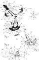
- the toe-piece according to the invention substantially comprises:
- the base 10 also has a relief 15 arranged along its front transverse edge 10c and extending in the transverse direction Y-Y by an amount slightly smaller than the interaxial distance L between two longitudinal arms 31b of a U-shaped elastic element 30 described below, so as to allow said arms 31b to pass in the vertical direction Z-Z.
- the relief 15 has a through-hole 15a in the transverse direction Y-Y suitable for inserting a transverse pin 16 with a length such that its opposite ends 16a project transversely from the relief 15 by an amount such as to overlap the longitudinal arms 31b of the "U", so as to interfere with them and prevent them from coming out during the various stages of operation of the toe-piece.
- the base 10 has, connected thereto, first and second jaws 20 situated opposite each other and symmetrical with respect to a longitudinal axis X-X approximately passing through the centre of the toe-piece; each jaw 20 is substantially formed by:
- a small ball 32b is arranged between the free end 32 of the arm 31b and the blind bottom of the respective seat 23 and is designed to facilitate rotation of the spring inside the seat during operation thereof.
- the elastic element 30 can therefore be operated by means of pressure applied to the base 31a of the "U" so as to switch from a raised rest position for keeping the jaws 20 in the closed position for holding the toe of the boot, into a lowered position, for rotational operation of the jaws towards the open position for inserting the toe.
- the flat parts of the base 10 adjacent to the sides 15a of the raised element 15 form the reaction fulcrum for rotation of the arms 31b.
- the sides 15a of the raised element 15 act preferably as reaction fulcrums for transverse deformation (curving) of the arms 31b during opening of the jaws 20.
- the transverse base 31a of the "U” is inserted inside a respective central transverse eyelet 41a of an operating lever 40 arranged in front of the toe-piece and the boot and formed by a body 41 extending in the longitudinal direction X-X; in this way the base 31a of the "U” forms a transverse axis of rotation of said lever 40.
- the body 41 of the lever comprises at least one part 41b behind said eyelet 41a in the longitudinal direction X-X, with a transverse dimension Y-Y suitable for being contained between the arms 31b of the "U” and having a free rear front surface 41c which is substantially flat for resting on the top surface S of the ski.
- the bottom free end 41b of the lever 40 also has two teeth 41e projecting outwards in opposite senses of the transverse direction Y-Y and designed to prevent rotation of the lever 40, by abutting against the lower respective arm 31b of the "U".
- the front free end 41d of the lever 40 is configured so that it may be easily operated by the user, in particular easily pushed downwards in the vertical direction Z-Z.
- the operating lever 40 facilitates operation of the elastic element 30 and therefore opening of the jaws 20 into the position for inserting the toe of the boot as well as locking of the elastic element and therefore the jaws in the closed position for holding the toe of the boot.
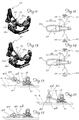
- Figs. 11 and 12 show a preferred embodiment of the adjusting means 50 which take the form of a slider 51 with suitably concave opposite transverse ends 51a for engagement with the arms 31b of the "U" on which it is therefore able to slide in the longitudinal direction from a position more retracted at the rear ( Figs. 11 and 12 ) to a position more advanced at the front ( Figs. 13 and 14 ).
- the presence of the slider 50 displaces the reaction fulcrum for curving of the elastic element 30 from the sides 15a of the raised part 15 to the concave sides 51a of said slider 50, resulting in a different overall elasticity of the elastic element and therefore resistance to release of the toe-piece.
- the slider may be displaced in a substantially continuous manner, allowing a corresponding modulation of the resistance to release of the toe-piece and, once the desired position has been reached, which may be marked by notches or an indication of the corresponding reaction kilograms, the slider may be locked by means of a locking plate 52 which can be locked to the slider by means of a fixing grub-screw 53 and the opposite ends of which push against the arms 31b of the "U".
- the slider may be locked in position along the arms 31b by tightening the grub-screw 53 against said slider, while in order to vary the position of the slider it is sufficient to slacken the grub-screw, slide the slider to the desired position and then tighten again the grub-screw 53.
- the toe-piece may be provided with an element 60 for inserting so-called ski-touring rampants (shown only in Fig. 1 ) positioned at the rear, in the longitudinal direction X-X, of the base plate 100.
- the element 60 ( Fig.
- the toe-piece according to the invention may be realized with a different configuration of the elastic element 130 which, in this version, has a relative angle ⁇ , between the bent ends 132 of the respective arms 31 and a plane parallel to the plane of the base plate, with a sign opposite to that of the preceding case; this results in a stable position of the elastic element 130 rotated in the anti-clockwise direction downwards and a consequent rest configuration of the toe-piece with jaws 20 rotated in the open position.
- Operation of the toe-piece in this case occurs by means of a pulling force exerted on the base 31 of the elastic element 130 which causes the downwards rotation of the ends 132 connected to said jaws, resulting in elastic deformation of the former with respect to the corresponding arm 31b such as to bring the elastic element into a second stable position with the jaws rotated into the closed position for engagement with the toe of the boot.
- the presence and the rotation of the operating lever 40 may determine the various conditions of use of the toe-piece, as already described for the first embodiment thereof.
Landscapes
- Footwear And Its Accessory, Manufacturing Method And Apparatuses (AREA)
Claims (13)
- Fußspitzenstück für Langlaufskibindungen, das sich in eine longitudinale Längsrichtung (X-X) des Fußspitzenstücks, transversale Querrichtung (Y-Y) und vertikale Richtung (Z-Z), senkrecht zu den vorgenannten Richtungen erstreckt und umfasst:- eine Grundplatte (10) versehen mit Löchern (11) zur Fixierung mittels Schrauben (11a) auf einer Oberfläche (S) eines Skis (1), die sich in der longitudinalen Richtung von einer vorderen Spitze (1a) zu einem hinteren Endstück erstreckt, wobei die Grundplatte (10) verbunden ist mit:- zwei bezüglich einer longitudinalen Achse (X-X) symmetrisch und sich gegenüberliegend angeordneten Klemmbacken (20), jede ausgestattet mit einem transversalen Schenkel (21b) und einem vertikalen Schenkel (21a) mit einem transversalen konischen Stift (22) ausgestattet, wobei die Schenkel so ausgestaltet sind, dass sie sich um eine Achse (13) drehen, die im wesentlichen parallel zur Grundplatte (10) und zur Längsrichtung (X-X) ist, zwischen einer geschlossenen/geöffneten Stellung zum Halten/Einsetzen und Freigeben der Fußspitze (2a) des Skistiefels (2) und einer geöffneten/geschlossenen Stellung zum Freigeben und Einsetzen/Halten der Fußspitze (2a),- einem einteiligen elastischen Element (30; 130) mit zwei Enden (32; 132), die mit genannten transversalen Schenkeln (21b) zusammenwirken, dadurch gekennzeichnet, dass das einteilige elastische Element (30; 130) aus einer Raststellung, die der geschlossenen/geöffneten Stellung der Klemmbacken (20) entspricht, in eine gedrehte und elastisch verformte Stellung zur rotatorischen Betätigung der Klemmbacken (20) in die geöffnete/geschlossene Stellung zum Einsetzen und Freigeben/Halten der Fußspitze des Skistiefels (2) innerhalb des Fußspitzenteils betätigt werden kann.
- Fußspitzenstück nach Anspruch 1, dadurch gekennzeichnet, dass die genannte Raststellung des elastischen Elements (30) gedreht/aufgestellt wird und dass dieser Vorgang durch Aufbringen von Druck darauf ausgeführt wird.
- Fußspitzenstück nach Anspruch 1, dadurch gekennzeichnet, dass die genannte Raststellung des elastischen Elements (130) gedreht/abgesenkt wird und dass dieser Vorgang durch Aufbringen einer Zugkraft darauf ausgeführt wird.
- Fußspitzenstück nach Anspruch 1, dadurch gekennzeichnet, dass die Grundplatte (10) umfasst:- ein erstes Paar hervorstehender Stützen (12), die sich in der longitudinalen Richtung (X-X) gegenüberliegen und entlang einer ersten longitudinalen Kante (10a) der Grundplatte (10) angeordnet sind;- ein zweites Paar vertikaler Stützen (12), die sich in der longitudinalen Richtung (X-X) gegenüberliegen und bezüglich des ersten Paars (12) symmetrisch auf einer der ersten Kante (10a) gegenüberliegenden zweiten longitudinalen Kante (10b) der Grundplatte (10) angeordnet sind;wobei jede Stütze (12) eine longitudinale Durchgangsbohrung (12a) aufweist, die ausgestaltet ist, einen longitudinalen Stift (13) aufzunehmen, der die entsprechenden Klemmbacken in die jeweiligen Stützen (12) fesselt, wobei genannter Stift (13) eine longitudinale Achse zur Drehung der jeweiligen Klemmbacke (20) zwischen der normalen geschlossenen Stellung und der geöffneten Stellung bildet.
- Fußspitzenstück nach irgendeinem der vorherigen Ansprüche, dadurch gekennzeichnet, dass das elastische Element (30; 130) durch einen U-förmigen Körper gebildet wird, der aufweist:- eine Basis (31a) des "U", die sich in die transversale Richtung (Y-Y) erstreckt und vor und außerhalb der Grundplatte (10) in der longitudinalen Richtung (X-X) angeordnet ist;- Schenkel (31b) des "U", welche sich ausgehend von der Basis (31a) in longitudinaler Richtung erstrecken und aufweisen:- jeweils ein hinteres freies Ende (32, 132), das in transversaler Richtung (Y-Y) nach außen und in Richtung auf einen zugehörigen Sitz (23) des transversalen Schenkels (21b) der jeweiligen Klemmbacke (20) gebogen ist, wobei sie innerhalb des Sitzes (23) fest aufgenommen sind.
- Fußspitzenstück nach dem vorherigen Anspruch, dadurch gekennzeichnet, dass die freien Enden (32; 132) des elastischen Elements (30; 130) mit dem jeweiligen longitudinalen Schenkel (31b) mittels eines gekrümmten Abschnitts verbunden sind, der einen relativen Winkel (α) in einer Ebene (X-Y) parallel zur Grundplatte (10) und einen spitzen Winkel (β) mit einer Ebene (X-Y) parallel zur Grundplatte (10) bildet.
- Fußspitzenstück nach irgendeinem der Ansprüche 5 bis 6, dadurch gekennzeichnet, dass die Grundplatte (10) eine entlang ihrer vorderen transversalen Kante (10c) angeordnete Entlastung (15) aufweist, die sich in der transversalen Richtung (Y-Y) um einen Betrag erstreckt, der geringfügig kleiner ist als der interaxiale Abstand (L) zwischen den beiden longitudinalen Schenkeln (31b) des U-förmigen elastischen Elements (30), um ein Einsetzen in vertikaler Richtung (Z-Z) zwischen den genannten Schenkeln (31b) zu ermöglichen.
- Fußspitzenstück nach dem vorherigen Anspruch, dadurch gekennzeichnet, dass die Entlastung (15) in ihrem oberen Teil eine Durchgangsbohrung (15a) in der transversalen Richtung aufweist, die zum Einführen eines transversalen Stifts (16) geeignet ist, wobei der Stift (16) eine Länge aufweist, so dass seine gegenüberliegenden Enden (16a) transversal aus der Entlastung (15) hervorstehen, und die longitudinalen Schenkel (31b) des "U" überlappen, um diese in vertikaler Richtung zu behindern und am Heraustreten zu hindern.
- Fußspitzenstück nach dem vorherigen Anspruch, dadurch gekennzeichnet, dass die flachen Seiten der Grundplatte (10), welche an die Seiten (15a) der Entlastung (15) angrenzen, einen Reaktionsdrehpunkt zur Drehung der longitudinalen Schenkel (31b) des elastischen Elements (30) bilden.
- Fußspitzenstück nach irgendeinem der vorherigen Ansprüche, dadurch gekennzeichnet, dass es einen Betätigungshebel (40) umfasst, der vor der Grundplatte (10) angeordnet ist und von einem sich in longitudinaler Richtung (X-X) erstreckenden Körper (41) gebildet wird und eine zentrale transversale Öse (41a) aufweist, in der die transversale Basis (31a) des "U" des Körpers des elastischen Elements (30; 130) eingesetzt ist, wobei die genannte Basis eine transversale Rotationsachse des genannten Hebels (40) bildet.
- Fußspitzenstück nach irgendeinem der vorherigen Ansprüche, dadurch gekennzeichnet, dass es eine Einrichtung (50) zum Einstellen der elastischen Widerstandskraft des elastischen Elements (30; 130) des Fußspitzenstücks umfasst, wodurch der Sicherheitsauslösewert des Fußspitzenstücks eingestellt wird.
- Fußspitzenstück nach dem vorherigen Anspruch, dadurch gekennzeichnet, dass die genannte Einstelleinrichtung einen Schieber (51) mit gegenüberliegenden transversalen Enden (51a) umfasst, welche geeignet konkav sind für den Eingriff mit den Schenkeln (31b) des "U", auf denen der Schieber in longitudinaler Richtung gleiten kann.
- Fußspitzenstück nach dem vorherigen Anspruch, dadurch gekennzeichnet, dass die genannte Einstelleinrichtung eine Verschlussplatte (52) umfasst, deren gegenüberliegende Enden gegen die Schenkel (31b) des "U" drücken und mittels einer Fixier-Madenschraube (53) an dem Schieber arretiert werden können.
Applications Claiming Priority (1)
| Application Number | Priority Date | Filing Date | Title |
|---|---|---|---|
| ITMI20140901 | 2014-05-19 |
Publications (2)
| Publication Number | Publication Date |
|---|---|
| EP2946817A1 EP2946817A1 (de) | 2015-11-25 |
| EP2946817B1 true EP2946817B1 (de) | 2017-05-03 |
Family
ID=51230010
Family Applications (1)
| Application Number | Title | Priority Date | Filing Date |
|---|---|---|---|
| EP15167803.4A Active EP2946817B1 (de) | 2014-05-19 | 2015-05-15 | Zehenstück für skitourenbindungen |
Country Status (2)
| Country | Link |
|---|---|
| US (1) | US9440137B2 (de) |
| EP (1) | EP2946817B1 (de) |
Cited By (1)
| Publication number | Priority date | Publication date | Assignee | Title |
|---|---|---|---|---|
| US20210308552A1 (en) * | 2019-06-22 | 2021-10-07 | Salewa Sport Ag | Front unit for a touring binding |
Families Citing this family (6)
| Publication number | Priority date | Publication date | Assignee | Title |
|---|---|---|---|---|
| EP2929919B1 (de) * | 2014-04-09 | 2018-05-30 | Salomon S.A.S. | Skibindung |
| DE102017120701A1 (de) * | 2017-09-07 | 2019-03-07 | Marker Deutschland Gmbh | Ultraleichter Vorderbacken |
| EP3566754B1 (de) * | 2018-05-08 | 2022-08-17 | Fritschi AG - Swiss Bindings | Frontautomat für eine skibindung |
| DE102020203280A1 (de) * | 2020-03-13 | 2021-09-16 | Salewa Sport Ag | Vordereinheit für eine Skibindung mit definiertem Öffnungsmaß |
| IT202000012502A1 (it) * | 2020-05-27 | 2021-11-27 | Atk Sports S R L | Inserto anteriore per scarpone da sci alpinismo, per l'aggancio dello scarpone ad un attacco da sci alpinismo |
| USD1082989S1 (en) * | 2023-07-27 | 2025-07-08 | Brunk Industries, Inc. | Ski binding beam spring |
Citations (1)
| Publication number | Priority date | Publication date | Assignee | Title |
|---|---|---|---|---|
| EP2687275A1 (de) * | 2012-07-19 | 2014-01-22 | Salomon S.A.S. | Vordere Haltevorrichtungen eines Gleitbrettes |
Family Cites Families (14)
| Publication number | Priority date | Publication date | Assignee | Title |
|---|---|---|---|---|
| JPS4855970U (de) * | 1971-10-27 | 1973-07-18 | ||
| DE2906485C2 (de) * | 1979-02-20 | 1982-06-16 | Geze Gmbh, 7250 Leonberg | Langlaufbindung mit einem einen vorderen Sohlenüberstand abstützenden Bindungsteil |
| US4322090A (en) * | 1980-02-13 | 1982-03-30 | Loughney Charles E | Ski mountaineering binding |
| DE3204650A1 (de) * | 1982-02-10 | 1983-08-18 | Marker Patentverwertungsgesellschaft mbH, 6340 Baar | Tourenskibindung |
| ITMI20051429A1 (it) * | 2005-07-22 | 2007-01-23 | Ski Trab S R L | Puntale per attacchi da sci |
| EP2300111B1 (de) * | 2008-04-03 | 2018-01-31 | G3 Genuine Guide Gear Inc. | Zeheneinheit für tourenskibindung |
| DE202010000614U1 (de) * | 2010-01-05 | 2011-05-26 | Salewa Sport Ag | Skischuh und Bindungssystem umfassend einen Skischuh und eine Skibindung |
| DE102010029647A1 (de) * | 2010-06-02 | 2011-12-08 | Salewa Sport Ag | Tourenbindung |
| DE102012201816B4 (de) * | 2012-02-07 | 2022-10-20 | Fritz Barthel | Vordereinheit für eine Gleitbrettbindung mit ersten und zweiten Eingriffsmitteln |
| ITBO20120243A1 (it) * | 2012-05-04 | 2013-11-05 | Atk Race Srl | Puntale per attacco da sci-alpinismo |
| DE102012207959B4 (de) * | 2012-05-11 | 2020-11-12 | Fritz Barthel | Vordereinheit einer Gleitbrettbindung und Gleitbrettbindung |
| FR2991592B1 (fr) * | 2012-06-12 | 2016-08-26 | Rossignol Sa | Butee a declenchement automatique en torsion |
| ITBO20120645A1 (it) * | 2012-11-28 | 2014-05-29 | Atk Race Srl | Dispositivo per il bloccaggio amovibile della parte centrale-anteriore di uno scarpone da sci alla tavola dello sci per attuare la tecnica telemark |
| FR3002460B1 (fr) * | 2013-02-22 | 2017-08-25 | Rossignol Sa | Butee a declenchement automatique en torsion |
-
2015
- 2015-05-15 EP EP15167803.4A patent/EP2946817B1/de active Active
- 2015-05-19 US US14/716,439 patent/US9440137B2/en not_active Expired - Fee Related
Patent Citations (1)
| Publication number | Priority date | Publication date | Assignee | Title |
|---|---|---|---|---|
| EP2687275A1 (de) * | 2012-07-19 | 2014-01-22 | Salomon S.A.S. | Vordere Haltevorrichtungen eines Gleitbrettes |
Cited By (3)
| Publication number | Priority date | Publication date | Assignee | Title |
|---|---|---|---|---|
| US20210308552A1 (en) * | 2019-06-22 | 2021-10-07 | Salewa Sport Ag | Front unit for a touring binding |
| US11648456B2 (en) * | 2019-06-22 | 2023-05-16 | Salewa Sport Ag | Front unit for a touring binding |
| USRE50789E1 (en) * | 2020-06-22 | 2026-02-10 | Salewa Sport Ag | Front unit for a touring binding |
Also Published As
| Publication number | Publication date |
|---|---|
| US20150328529A1 (en) | 2015-11-19 |
| US9440137B2 (en) | 2016-09-13 |
| EP2946817A1 (de) | 2015-11-25 |
Similar Documents
| Publication | Publication Date | Title |
|---|---|---|
| EP2946817B1 (de) | Zehenstück für skitourenbindungen | |
| EP1907078B1 (de) | Zehenstück für skibindungen | |
| EP3300778B1 (de) | Zeheneinheit für eine alpine tourenbindung | |
| EP2281614A1 (de) | Fersenteil mit zwei-armiger Vordergabel zum Einrasten mit Bolzen am Schuh | |
| US10010782B2 (en) | Heel-piece for binding a boot on a gliding board | |
| US5944337A (en) | Automatic binding device | |
| US9308433B2 (en) | Front unit for a binding device and retractable pins device | |
| US5518264A (en) | Free heel/anterior release ski binding | |
| US20130087992A1 (en) | Automatic front unit | |
| US9452343B2 (en) | SKI binding with forefoot fixing module | |
| EP2243388A2 (de) | Skistiefel mit Mitteln zur Betätigung von entsprechenden Halteelementen von Tourenskibindungen | |
| RU2526289C2 (ru) | Флексор с крепежной скобой | |
| EP2911541B1 (de) | Skischuh | |
| EP3155920A1 (de) | Verankerungsplatte für eine verschlussvorrichtung für sportschuhe | |
| US4607859A (en) | Safety ski binding | |
| EP0448009B1 (de) | Sicherheitsskibindung | |
| US11524220B2 (en) | Ski binding | |
| EP2489415A1 (de) | Vorderbacken für Tourenbindung | |
| EP1669113A1 (de) | Skibindung | |
| JPS5836988B2 (ja) | カイホウジザイノスキ−ビンデイング | |
| NO793797L (no) | Stoevel for langrenns- eller turski. |
Legal Events
| Date | Code | Title | Description |
|---|---|---|---|
| PUAI | Public reference made under article 153(3) epc to a published international application that has entered the european phase |
Free format text: ORIGINAL CODE: 0009012 |
|
| AK | Designated contracting states |
Kind code of ref document: A1 Designated state(s): AL AT BE BG CH CY CZ DE DK EE ES FI FR GB GR HR HU IE IS IT LI LT LU LV MC MK MT NL NO PL PT RO RS SE SI SK SM TR |
|
| AX | Request for extension of the european patent |
Extension state: BA ME |
|
| RBV | Designated contracting states (corrected) |
Designated state(s): AL AT BE BG CH CY CZ DE DK EE ES FI FR GB GR HR HU IE IS IT LI LT LU LV MC MK MT NL NO PL PT RO RS SE SI SK SM TR |
|
| 17P | Request for examination filed |
Effective date: 20160519 |
|
| RIC1 | Information provided on ipc code assigned before grant |
Ipc: A63C 9/086 20120101ALI20160930BHEP Ipc: A63C 9/08 20120101AFI20160930BHEP Ipc: A63C 9/085 20120101ALI20160930BHEP |
|
| GRAP | Despatch of communication of intention to grant a patent |
Free format text: ORIGINAL CODE: EPIDOSNIGR1 |
|
| STAA | Information on the status of an ep patent application or granted ep patent |
Free format text: STATUS: GRANT OF PATENT IS INTENDED |
|
| INTG | Intention to grant announced |
Effective date: 20161124 |
|
| GRAS | Grant fee paid |
Free format text: ORIGINAL CODE: EPIDOSNIGR3 |
|
| GRAA | (expected) grant |
Free format text: ORIGINAL CODE: 0009210 |
|
| STAA | Information on the status of an ep patent application or granted ep patent |
Free format text: STATUS: THE PATENT HAS BEEN GRANTED |
|
| AK | Designated contracting states |
Kind code of ref document: B1 Designated state(s): AL AT BE BG CH CY CZ DE DK EE ES FI FR GB GR HR HU IE IS IT LI LT LU LV MC MK MT NL NO PL PT RO RS SE SI SK SM TR |
|
| REG | Reference to a national code |
Ref country code: GB Ref legal event code: FG4D |
|
| REG | Reference to a national code |
Ref country code: AT Ref legal event code: REF Ref document number: 889328 Country of ref document: AT Kind code of ref document: T Effective date: 20170515 Ref country code: CH Ref legal event code: EP |
|
| REG | Reference to a national code |
Ref country code: FR Ref legal event code: PLFP Year of fee payment: 3 Ref country code: IE Ref legal event code: FG4D |
|
| REG | Reference to a national code |
Ref country code: DE Ref legal event code: R096 Ref document number: 602015002495 Country of ref document: DE |
|
| REG | Reference to a national code |
Ref country code: NL Ref legal event code: MP Effective date: 20170503 |
|
| REG | Reference to a national code |
Ref country code: AT Ref legal event code: MK05 Ref document number: 889328 Country of ref document: AT Kind code of ref document: T Effective date: 20170503 |
|
| REG | Reference to a national code |
Ref country code: LT Ref legal event code: MG4D |
|
| PG25 | Lapsed in a contracting state [announced via postgrant information from national office to epo] |
Ref country code: HR Free format text: LAPSE BECAUSE OF FAILURE TO SUBMIT A TRANSLATION OF THE DESCRIPTION OR TO PAY THE FEE WITHIN THE PRESCRIBED TIME-LIMIT Effective date: 20170503 Ref country code: ES Free format text: LAPSE BECAUSE OF FAILURE TO SUBMIT A TRANSLATION OF THE DESCRIPTION OR TO PAY THE FEE WITHIN THE PRESCRIBED TIME-LIMIT Effective date: 20170503 Ref country code: AT Free format text: LAPSE BECAUSE OF FAILURE TO SUBMIT A TRANSLATION OF THE DESCRIPTION OR TO PAY THE FEE WITHIN THE PRESCRIBED TIME-LIMIT Effective date: 20170503 Ref country code: FI Free format text: LAPSE BECAUSE OF FAILURE TO SUBMIT A TRANSLATION OF THE DESCRIPTION OR TO PAY THE FEE WITHIN THE PRESCRIBED TIME-LIMIT Effective date: 20170503 Ref country code: NO Free format text: LAPSE BECAUSE OF FAILURE TO SUBMIT A TRANSLATION OF THE DESCRIPTION OR TO PAY THE FEE WITHIN THE PRESCRIBED TIME-LIMIT Effective date: 20170803 Ref country code: GR Free format text: LAPSE BECAUSE OF FAILURE TO SUBMIT A TRANSLATION OF THE DESCRIPTION OR TO PAY THE FEE WITHIN THE PRESCRIBED TIME-LIMIT Effective date: 20170804 Ref country code: LT Free format text: LAPSE BECAUSE OF FAILURE TO SUBMIT A TRANSLATION OF THE DESCRIPTION OR TO PAY THE FEE WITHIN THE PRESCRIBED TIME-LIMIT Effective date: 20170503 |
|
| PG25 | Lapsed in a contracting state [announced via postgrant information from national office to epo] |
Ref country code: PL Free format text: LAPSE BECAUSE OF FAILURE TO SUBMIT A TRANSLATION OF THE DESCRIPTION OR TO PAY THE FEE WITHIN THE PRESCRIBED TIME-LIMIT Effective date: 20170503 Ref country code: BG Free format text: LAPSE BECAUSE OF FAILURE TO SUBMIT A TRANSLATION OF THE DESCRIPTION OR TO PAY THE FEE WITHIN THE PRESCRIBED TIME-LIMIT Effective date: 20170803 Ref country code: RS Free format text: LAPSE BECAUSE OF FAILURE TO SUBMIT A TRANSLATION OF THE DESCRIPTION OR TO PAY THE FEE WITHIN THE PRESCRIBED TIME-LIMIT Effective date: 20170503 Ref country code: SE Free format text: LAPSE BECAUSE OF FAILURE TO SUBMIT A TRANSLATION OF THE DESCRIPTION OR TO PAY THE FEE WITHIN THE PRESCRIBED TIME-LIMIT Effective date: 20170503 Ref country code: LV Free format text: LAPSE BECAUSE OF FAILURE TO SUBMIT A TRANSLATION OF THE DESCRIPTION OR TO PAY THE FEE WITHIN THE PRESCRIBED TIME-LIMIT Effective date: 20170503 Ref country code: NL Free format text: LAPSE BECAUSE OF FAILURE TO SUBMIT A TRANSLATION OF THE DESCRIPTION OR TO PAY THE FEE WITHIN THE PRESCRIBED TIME-LIMIT Effective date: 20170503 Ref country code: IS Free format text: LAPSE BECAUSE OF FAILURE TO SUBMIT A TRANSLATION OF THE DESCRIPTION OR TO PAY THE FEE WITHIN THE PRESCRIBED TIME-LIMIT Effective date: 20170903 |
|
| PG25 | Lapsed in a contracting state [announced via postgrant information from national office to epo] |
Ref country code: EE Free format text: LAPSE BECAUSE OF FAILURE TO SUBMIT A TRANSLATION OF THE DESCRIPTION OR TO PAY THE FEE WITHIN THE PRESCRIBED TIME-LIMIT Effective date: 20170503 Ref country code: CZ Free format text: LAPSE BECAUSE OF FAILURE TO SUBMIT A TRANSLATION OF THE DESCRIPTION OR TO PAY THE FEE WITHIN THE PRESCRIBED TIME-LIMIT Effective date: 20170503 Ref country code: DK Free format text: LAPSE BECAUSE OF FAILURE TO SUBMIT A TRANSLATION OF THE DESCRIPTION OR TO PAY THE FEE WITHIN THE PRESCRIBED TIME-LIMIT Effective date: 20170503 Ref country code: RO Free format text: LAPSE BECAUSE OF FAILURE TO SUBMIT A TRANSLATION OF THE DESCRIPTION OR TO PAY THE FEE WITHIN THE PRESCRIBED TIME-LIMIT Effective date: 20170503 Ref country code: SK Free format text: LAPSE BECAUSE OF FAILURE TO SUBMIT A TRANSLATION OF THE DESCRIPTION OR TO PAY THE FEE WITHIN THE PRESCRIBED TIME-LIMIT Effective date: 20170503 |
|
| REG | Reference to a national code |
Ref country code: DE Ref legal event code: R097 Ref document number: 602015002495 Country of ref document: DE |
|
| REG | Reference to a national code |
Ref country code: IE Ref legal event code: MM4A |
|
| PG25 | Lapsed in a contracting state [announced via postgrant information from national office to epo] |
Ref country code: IT Free format text: LAPSE BECAUSE OF FAILURE TO SUBMIT A TRANSLATION OF THE DESCRIPTION OR TO PAY THE FEE WITHIN THE PRESCRIBED TIME-LIMIT Effective date: 20170503 Ref country code: SM Free format text: LAPSE BECAUSE OF FAILURE TO SUBMIT A TRANSLATION OF THE DESCRIPTION OR TO PAY THE FEE WITHIN THE PRESCRIBED TIME-LIMIT Effective date: 20170503 |
|
| PLBE | No opposition filed within time limit |
Free format text: ORIGINAL CODE: 0009261 |
|
| STAA | Information on the status of an ep patent application or granted ep patent |
Free format text: STATUS: NO OPPOSITION FILED WITHIN TIME LIMIT |
|
| PG25 | Lapsed in a contracting state [announced via postgrant information from national office to epo] |
Ref country code: LU Free format text: LAPSE BECAUSE OF NON-PAYMENT OF DUE FEES Effective date: 20170515 |
|
| 26N | No opposition filed |
Effective date: 20180206 |
|
| REG | Reference to a national code |
Ref country code: BE Ref legal event code: MM Effective date: 20170531 |
|
| PG25 | Lapsed in a contracting state [announced via postgrant information from national office to epo] |
Ref country code: IE Free format text: LAPSE BECAUSE OF NON-PAYMENT OF DUE FEES Effective date: 20170515 |
|
| PG25 | Lapsed in a contracting state [announced via postgrant information from national office to epo] |
Ref country code: SI Free format text: LAPSE BECAUSE OF FAILURE TO SUBMIT A TRANSLATION OF THE DESCRIPTION OR TO PAY THE FEE WITHIN THE PRESCRIBED TIME-LIMIT Effective date: 20170503 |
|
| REG | Reference to a national code |
Ref country code: FR Ref legal event code: PLFP Year of fee payment: 4 |
|
| PG25 | Lapsed in a contracting state [announced via postgrant information from national office to epo] |
Ref country code: BE Free format text: LAPSE BECAUSE OF NON-PAYMENT OF DUE FEES Effective date: 20170531 |
|
| PG25 | Lapsed in a contracting state [announced via postgrant information from national office to epo] |
Ref country code: MT Free format text: LAPSE BECAUSE OF NON-PAYMENT OF DUE FEES Effective date: 20170515 |
|
| REG | Reference to a national code |
Ref country code: CH Ref legal event code: PL |
|
| PG25 | Lapsed in a contracting state [announced via postgrant information from national office to epo] |
Ref country code: LI Free format text: LAPSE BECAUSE OF NON-PAYMENT OF DUE FEES Effective date: 20180531 Ref country code: CH Free format text: LAPSE BECAUSE OF NON-PAYMENT OF DUE FEES Effective date: 20180531 |
|
| PG25 | Lapsed in a contracting state [announced via postgrant information from national office to epo] |
Ref country code: HU Free format text: LAPSE BECAUSE OF FAILURE TO SUBMIT A TRANSLATION OF THE DESCRIPTION OR TO PAY THE FEE WITHIN THE PRESCRIBED TIME-LIMIT; INVALID AB INITIO Effective date: 20150515 Ref country code: MC Free format text: LAPSE BECAUSE OF FAILURE TO SUBMIT A TRANSLATION OF THE DESCRIPTION OR TO PAY THE FEE WITHIN THE PRESCRIBED TIME-LIMIT Effective date: 20170503 |
|
| PG25 | Lapsed in a contracting state [announced via postgrant information from national office to epo] |
Ref country code: CY Free format text: LAPSE BECAUSE OF FAILURE TO SUBMIT A TRANSLATION OF THE DESCRIPTION OR TO PAY THE FEE WITHIN THE PRESCRIBED TIME-LIMIT Effective date: 20170503 |
|
| PG25 | Lapsed in a contracting state [announced via postgrant information from national office to epo] |
Ref country code: MK Free format text: LAPSE BECAUSE OF FAILURE TO SUBMIT A TRANSLATION OF THE DESCRIPTION OR TO PAY THE FEE WITHIN THE PRESCRIBED TIME-LIMIT Effective date: 20170503 |
|
| GBPC | Gb: european patent ceased through non-payment of renewal fee |
Effective date: 20190515 |
|
| PG25 | Lapsed in a contracting state [announced via postgrant information from national office to epo] |
Ref country code: TR Free format text: LAPSE BECAUSE OF FAILURE TO SUBMIT A TRANSLATION OF THE DESCRIPTION OR TO PAY THE FEE WITHIN THE PRESCRIBED TIME-LIMIT Effective date: 20170503 |
|
| PG25 | Lapsed in a contracting state [announced via postgrant information from national office to epo] |
Ref country code: GB Free format text: LAPSE BECAUSE OF NON-PAYMENT OF DUE FEES Effective date: 20190515 |
|
| PG25 | Lapsed in a contracting state [announced via postgrant information from national office to epo] |
Ref country code: PT Free format text: LAPSE BECAUSE OF FAILURE TO SUBMIT A TRANSLATION OF THE DESCRIPTION OR TO PAY THE FEE WITHIN THE PRESCRIBED TIME-LIMIT Effective date: 20170503 |
|
| PG25 | Lapsed in a contracting state [announced via postgrant information from national office to epo] |
Ref country code: AL Free format text: LAPSE BECAUSE OF FAILURE TO SUBMIT A TRANSLATION OF THE DESCRIPTION OR TO PAY THE FEE WITHIN THE PRESCRIBED TIME-LIMIT Effective date: 20170503 |
|
| PGFP | Annual fee paid to national office [announced via postgrant information from national office to epo] |
Ref country code: DE Payment date: 20250529 Year of fee payment: 11 |
|
| PGFP | Annual fee paid to national office [announced via postgrant information from national office to epo] |
Ref country code: FR Payment date: 20250528 Year of fee payment: 11 |