EP2946868B1 - Verfahren zur herstellung einer versiegelten batterie - Google Patents
Verfahren zur herstellung einer versiegelten batterie Download PDFInfo
- Publication number
- EP2946868B1 EP2946868B1 EP13871543.8A EP13871543A EP2946868B1 EP 2946868 B1 EP2946868 B1 EP 2946868B1 EP 13871543 A EP13871543 A EP 13871543A EP 2946868 B1 EP2946868 B1 EP 2946868B1
- Authority
- EP
- European Patent Office
- Prior art keywords
- foil
- metal foil
- electrode terminal
- laminated
- laminated layers
- Prior art date
- Legal status (The legal status is an assumption and is not a legal conclusion. Google has not performed a legal analysis and makes no representation as to the accuracy of the status listed.)
- Active
Links
Images


Classifications
-
- B—PERFORMING OPERATIONS; TRANSPORTING
- B23—MACHINE TOOLS; METAL-WORKING NOT OTHERWISE PROVIDED FOR
- B23K—SOLDERING OR UNSOLDERING; WELDING; CLADDING OR PLATING BY SOLDERING OR WELDING; CUTTING BY APPLYING HEAT LOCALLY, e.g. FLAME CUTTING; WORKING BY LASER BEAM
- B23K11/00—Resistance welding; Severing by resistance heating
- B23K11/002—Resistance welding; Severing by resistance heating specially adapted for particular articles or work
- B23K11/0026—Welding of thin articles
-
- B—PERFORMING OPERATIONS; TRANSPORTING
- B23—MACHINE TOOLS; METAL-WORKING NOT OTHERWISE PROVIDED FOR
- B23K—SOLDERING OR UNSOLDERING; WELDING; CLADDING OR PLATING BY SOLDERING OR WELDING; CUTTING BY APPLYING HEAT LOCALLY, e.g. FLAME CUTTING; WORKING BY LASER BEAM
- B23K11/00—Resistance welding; Severing by resistance heating
- B23K11/10—Spot welding; Stitch welding
- B23K11/11—Spot welding
- B23K11/115—Spot welding by means of two electrodes placed opposite one another on both sides of the welded parts
-
- B—PERFORMING OPERATIONS; TRANSPORTING
- B23—MACHINE TOOLS; METAL-WORKING NOT OTHERWISE PROVIDED FOR
- B23K—SOLDERING OR UNSOLDERING; WELDING; CLADDING OR PLATING BY SOLDERING OR WELDING; CUTTING BY APPLYING HEAT LOCALLY, e.g. FLAME CUTTING; WORKING BY LASER BEAM
- B23K11/00—Resistance welding; Severing by resistance heating
- B23K11/16—Resistance welding; Severing by resistance heating taking account of the properties of the material to be welded
- B23K11/18—Resistance welding; Severing by resistance heating taking account of the properties of the material to be welded of non-ferrous metals
-
- B—PERFORMING OPERATIONS; TRANSPORTING
- B23—MACHINE TOOLS; METAL-WORKING NOT OTHERWISE PROVIDED FOR
- B23K—SOLDERING OR UNSOLDERING; WELDING; CLADDING OR PLATING BY SOLDERING OR WELDING; CUTTING BY APPLYING HEAT LOCALLY, e.g. FLAME CUTTING; WORKING BY LASER BEAM
- B23K11/00—Resistance welding; Severing by resistance heating
- B23K11/34—Preliminary treatment
-
- B—PERFORMING OPERATIONS; TRANSPORTING
- B23—MACHINE TOOLS; METAL-WORKING NOT OTHERWISE PROVIDED FOR
- B23K—SOLDERING OR UNSOLDERING; WELDING; CLADDING OR PLATING BY SOLDERING OR WELDING; CUTTING BY APPLYING HEAT LOCALLY, e.g. FLAME CUTTING; WORKING BY LASER BEAM
- B23K2103/00—Materials to be soldered, welded or cut
- B23K2103/08—Non-ferrous metals or alloys
- B23K2103/10—Aluminium or alloys thereof
-
- B—PERFORMING OPERATIONS; TRANSPORTING
- B23—MACHINE TOOLS; METAL-WORKING NOT OTHERWISE PROVIDED FOR
- B23K—SOLDERING OR UNSOLDERING; WELDING; CLADDING OR PLATING BY SOLDERING OR WELDING; CUTTING BY APPLYING HEAT LOCALLY, e.g. FLAME CUTTING; WORKING BY LASER BEAM
- B23K2103/00—Materials to be soldered, welded or cut
- B23K2103/08—Non-ferrous metals or alloys
- B23K2103/12—Copper or alloys thereof
-
- B—PERFORMING OPERATIONS; TRANSPORTING
- B23—MACHINE TOOLS; METAL-WORKING NOT OTHERWISE PROVIDED FOR
- B23K—SOLDERING OR UNSOLDERING; WELDING; CLADDING OR PLATING BY SOLDERING OR WELDING; CUTTING BY APPLYING HEAT LOCALLY, e.g. FLAME CUTTING; WORKING BY LASER BEAM
- B23K2103/00—Materials to be soldered, welded or cut
- B23K2103/18—Dissimilar materials
-
- H—ELECTRICITY
- H01—ELECTRIC ELEMENTS
- H01M—PROCESSES OR MEANS, e.g. BATTERIES, FOR THE DIRECT CONVERSION OF CHEMICAL ENERGY INTO ELECTRICAL ENERGY
- H01M10/00—Secondary cells; Manufacture thereof
- H01M10/05—Accumulators with non-aqueous electrolyte
- H01M10/052—Li-accumulators
- H01M10/0525—Rocking-chair batteries, i.e. batteries with lithium insertion or intercalation in both electrodes; Lithium-ion batteries
-
- H—ELECTRICITY
- H01—ELECTRIC ELEMENTS
- H01M—PROCESSES OR MEANS, e.g. BATTERIES, FOR THE DIRECT CONVERSION OF CHEMICAL ENERGY INTO ELECTRICAL ENERGY
- H01M50/00—Constructional details or processes of manufacture of the non-active parts of electrochemical cells other than fuel cells, e.g. hybrid cells
- H01M50/50—Current conducting connections for cells or batteries
- H01M50/531—Electrode connections inside a battery casing
- H01M50/538—Connection of several leads or tabs of wound or folded electrode stacks
-
- Y—GENERAL TAGGING OF NEW TECHNOLOGICAL DEVELOPMENTS; GENERAL TAGGING OF CROSS-SECTIONAL TECHNOLOGIES SPANNING OVER SEVERAL SECTIONS OF THE IPC; TECHNICAL SUBJECTS COVERED BY FORMER USPC CROSS-REFERENCE ART COLLECTIONS [XRACs] AND DIGESTS
- Y02—TECHNOLOGIES OR APPLICATIONS FOR MITIGATION OR ADAPTATION AGAINST CLIMATE CHANGE
- Y02E—REDUCTION OF GREENHOUSE GAS [GHG] EMISSIONS, RELATED TO ENERGY GENERATION, TRANSMISSION OR DISTRIBUTION
- Y02E60/00—Enabling technologies; Technologies with a potential or indirect contribution to GHG emissions mitigation
- Y02E60/10—Energy storage using batteries
Definitions
- the present invention relates to a method of manufacturing a sealed battery through resistance welding, according to the preamble of claim 1 (see, for example, JP2006-294567 ).
- sealed cells or batteries such as lithium ion batteries those have been known in which an electrode body is formed by winding a plurality of times a separator and metal foils, which are an aluminium foil coated with a positive-electrode active material and a copper foil coated with a negative-electrode active material, for example.
- the site (uncoated portion) not coated with an electrode active material serves as a joint portion (weld site) for joining the metal foil with an electrode terminal, to be used as a current collection portion.
- a strong insulating oxide film (aluminium oxide) is present on the surface of aluminium.
- a strong insulating oxide film aluminium oxide
- Patent Document 1 By providing the small hole, the oxide film of the aluminium foil is partially removed to make a path for current to flow therethrough, whereby conducting current performance or energization performance during resistance welding is improved.
- rolled copper foil is usually manufactured by repeating rolling/annealing of electrolytic copper into a foil shape.
- the electrolytic copper foil is manufactured in the following manner: performing energization in a copper sulfate vessel using a rotary drum made of stainless steel or the like as a cathode, to cause copper to precipitate (be electrodeposited) on the rotary drum; and then winding the precipitated copper into a roll shape.
- the rolled copper foil has limitation in the length of the foil, but the electrolytic copper foil does not have such limitation.
- copper foil that does not have limitation in the length of the foil is desired in order to realize higher capacity.
- the electrolytic copper foil is often used as the material for an electrode for a lithium ion battery.
- Patent Document 1 JP Laid-open Patent Publication No. 2006-326622
- JP58-181487 relates to welding a laminated member which sandwiches an electrical insulation layer easily to a mounting member. Two arcuate notches are formed and electrical contacts are applied at the notched part.
- JP2006-294567 relates to manufacturing an electric storage device.
- One or more collector leads are connected to terminals for external connection by solid-state welding.
- the manufacturing method includes stacking collector parts and a terminal part, compressing the parts and connecting, by solid state welding, the compressed collector parts and terminal part by heating the compressed parts.
- a round nugget (alloy layer) is formed by the use of resistance heat generated from resistance welding, around a small hole provided by means of a puncturing needle in the weld site of laminated layers of an aluminium foil.
- the area of the nugget in this case is dependent on the diameter relative to the center of the small hole. That is, the area of the nugget obtained through resistance welding is dependent on the size in the width direction of a nugget formation allowable region (weld site). Therefore, if the width of the portion uncoated with the active material in the laminated layers of the aluminium foil is decreased, a sufficient area of the nugget cannot be secured. This also applies to the case of laminated layers of a copper foil.
- An object of the present invention is, by solving the above problems, to provide a method for manufacturing a laminated metal foil which enables easy and assured resistance-welding of laminated layers of a metal foil, and which enables securement of a sufficient area of a resistance-welded nugget (alloy layer); a method for manufacturing a sealed battery including the above method; and a sealed battery.
- a method of manufacturing a sealed battery according to the present invention is defined in claim 1.
- a further embodiment of the invention is defined in claim 2.
- the width of the linear notch gradually increases from lower layers toward upper layers in the lamination. Accordingly, when the cutter is to be pulled out, the resistance force at the notch ends of the laminated layers of the metal foil hindering the pulling out of the cutter is reduced, and thus, it becomes easy to pull out the cutter from the cut in the laminated layers of the metal foil. Therefore, in the first step, the linear notch can be formed in the laminated layers of the metal foil by the use of the cutter, and the cutter can be easily pulled out from the notch.
- resistance-welding of the laminated metal foil can be assuredly performed via the notch, and it is possible to secure a necessary area of the resistance welded nugget (alloy layer) having an elliptical shape extending along the notch even when the size in the width direction of the weld site is small.
- the cutter has an included angle of 10° or greater. Accordingly, pulling out of the cutter having the substantially V-shape is further facilitated, and the first step can be easily performed.
- the electrode for resistance welding in a state where an electrode terminal is further laminated on the weld site of the laminated layers of the metal foil, the electrode for resistance welding may be brought into press-contact with the electrode terminal, and then in this state, the weld site and the electrode terminal may be energized via the electrode to resistance-weld the electrode terminal and the laminated layers of the metal foil together.
- the electrode terminal and the laminated layers of the metal foil are joined together by forming a nugget which has an elliptical shape and surrounds the linear notch made by the use of the cutter.
- a nugget which has an elliptical shape and surrounds the linear notch made by the use of the cutter.
- the sealed battery having an electrode body including the electrode terminals and the laminated layers of the metal foils can be easily and assuredly manufactured through resistance welding.
- the copper foil is an electrolytic copper foil.
- the copper foil is an electrolytic copper foil.
- a method of manufacturing a laminated metal foil is a method in which a laminated metal foil composed of a plurality of laminated layers of a metal foil is manufactured through resistance welding.
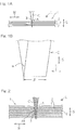
- Fig. 1A shows a laminated state of a plurality of layers of a metal foil 2.
- a laminated metal foil 1 having been subjected to resistance welding is used as an electrode body of a sealed battery such as a lithium ion battery, for example.
- the metal foil 2 aluminium foil is used for the positive electrode foil, and copper foil is used for the negative electrode foil, for example.
- the electrode terminal aluminium is used for the material of the positive electrode terminal, and copper is used for the material of the negative electrode terminal, for example.
- the present manufacturing method includes a first step and a second step.
- a cutter C is caused to penetrate a weld site A of the laminated metal foil 1 along a lamination direction S.
- Fig. 1B shows the cutter C whose longitudinal cross-sectional shape is a substantially V-shape.
- the cutter C is caused to penetrate the laminated layers of the metal foil 2 along the lamination direction S, thereby to form a notch 3 ( Fig. 4 ) being linear in a planar view and extending in a longitudinal direction L which is perpendicular to a width direction W of the laminated metal foil 1. Then, at notch ends 3a, the layers of the metal foil 2 adjacent to each other in the up-down direction are firmly bonded to each other.
- the cutter C having the substantially V-shape shown in Fig. 1B has an included angle ⁇ of 10° or greater, and preferably, 15° or greater. Accordingly, once the cutter C has cut into the laminated metal foil 1, the linear notch 3 is caused to have a cut shape in which the line width is small in a lower portion in the lamination of the laminated metal foil 1 and the line width gradually increases toward the upper portion thereof, because the cutter C has the substantially V-shape.
- the cutter C when the cutter C is to be pulled out after having formed the notch 3 in the laminated metal foil 1, compared with a case of a conventional needle shape, the resistance force at each notch end 3a of the layers of the metal foil that are stacked, the resistance force hindering the pulling out of the cutter C, is reduced as a whole.
- the cutter C can be easily pulled out from the notch 3 in the laminated metal foil 1.
- the included angle ⁇ is 90° or smaller. When the included angle ⁇ exceeds 90°, it is easy to pull out the cutter C but is difficult to form the notch 3.
- the cutter C has a cutting edge length ⁇ of 3 mm or greater, and preferably, 5 mm or greater. Any dimension in the longitudinal direction L of the notch 3 can be set if the cutter C is to be used a plurality of times along the longitudinal direction L.
- a width dimension d of the notch 3 shown in Fig. 5 is set as 0.1 mm ⁇ d ⁇ 1.0 mm.
- the width dimension d is set as 0.3 mm ⁇ d ⁇ 0.8 mm.
- the blade edge of the cutter C is too thin, which makes it difficult to form the notch 3.
- the notch 3 may not be completely closed after resistance welding. With the dimension range above, it is possible to more easily form the notch 3 and to more assuredly perform resistance welding.
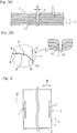
- Fig. 3A shows a state after the notch 3 has been formed in the laminated metal foil 1
- Fig. 3B is an enlarged cross-sectional front view of a principal part thereof.
- a surface of the copper foil has been subjected to roughing treatment.
- fine dimples X are formed at random on the surface of the copper foil having been subjected to roughing treatment.
- impurity (insulator) Y such as etchant remains in the fine dimples X.
- the laminated body composed of laminated layers of the copper foil having the impurity Y remaining on the surface thereof current is further less likely to flow along the lamination direction, which makes it further difficult to perform resistance welding.
- the notch 3 is formed as described above.
- the impurity Y is forcedly taken out from the fine dimples X to be discharged, because the cutter C pushes to widen the notch end 3a in the laminated body of the copper foil, and accordingly, the lamination surface of the copper foil is deformed.
- the layers of the copper foil adjacent to each other are further firmly adhered to each other, and the conduction portion R ( Fig. 5 ) that allows current to further easily flow therethrough is formed.
- the cuts 3 each having the line shape with the predetermined width are formed at positions in opposite end portions (left and right in Fig. 4 ) in the width direction W of the metal foil 2, so as to extend in the direction L perpendicular to the width direction W.
- the cuts 3 without decreasing the dimension in the width direction of the center portion in the width direction W of the metal foil excluding the weld sites A, it is possible to sufficiently secure the areas of the notches 3 which will serve as the main parts of the weld sites A.
- electrodes E, E for resistance welding of a resistance welding machine bring the laminated metal foil 1 into press-contact therewith in a sandwiched manner at the weld site A around the notch 3, and then the weld site A is energized via the electrodes E, thereby to perform resistance welding on the laminated metal foil 1.
- a resistance welding machine for example, energization is performed with an electrode terminal 4 laminated on the laminated metal foil 1, whereby the laminated metal foil 1 and the electrode terminal 4 are welded together.
- a nugget (alloy layer) 5 is formed in the notch 3, and the laminated metal foil 1 and the electrode terminal 4 are melt to be joined together.
- the width dimension D of the notch 3 after resistance welding is set as 1.0 mm ⁇ D ⁇ 2.0 mm, and preferably, is set as 1.3 mm ⁇ D ⁇ 1.8 mm.
- the width dimension D is set as D ⁇ 1.0 mm, insufficient welding may be caused.
- the width dimension D is set as 2.0 mm ⁇ D, resistance welding time may become unnecessarily too long.
- the width of the linear notch 3 gradually increases from lower layers toward upper layers in the lamination.
- the resistance force at each notch end 3a of the laminated metal foil 1 hindering the pulling out of the cutter C is reduced, and thus, it becomes easy to pull out the cutter C from the notch 3 in the laminated metal foil 1.
- the linear notch 3 can be formed in the laminated metal foil 1 by the use of the cutter C, and the cutter C can be easily pulled out from the notch 3.
- resistance-welding of the laminated metal foil 1 can be assuredly performed via the notch 3, and it is possible to secure a sufficient area of the resistance-welded nugget (alloy layer) 5 having an elliptical shape extending along the notch 3 even when the size in the width direction W of the weld site A is small.
- the electrode terminal may be subjected to burring processing, to be formed into a terminal with an elliptical burr, for example, and this burr portion may be used as the cutter C.
- the laminated metal foil and the electrode terminal are brought into press-contact with each other by the use of the electrodes E, E; a cut having an elliptical shape and a line shape is formed in the laminated metal foil by the use of the cutter C being the burr portion; and in this state, the electrodes E, E are energized to resistance-weld the laminated metal foil and the electrode terminal with the burr together via the cut, whereby a nugget (alloy layer) is formed in the cut.
- the first step and the second step are not separately but continuously performed as one step, and thus, manufacturing time can be shortened.
- the sealed battery 7 is a lithium ion battery, for example, and an electrode body 20 serving as a power generating element is housed in an exterior 10.
- a positive electrode terminal 31 and a negative electrode terminal 32 which are to be connected to the electrode body 20 are provided at opposite ends in the width direction W, so as to project in the outward direction (upward direction in Fig. 7 ) L from the exterior 10.
- the exterior 10 includes: a container 11 which contains the electrode body 20; and a cap 12 to which the positive electrode terminal 31 and the negative electrode terminal 32 are fixed.
- a container 11 which contains the electrode body 20
- a cap 12 to which the positive electrode terminal 31 and the negative electrode terminal 32 are fixed.
- one face of the container 11 is open, and the open face is closed with the cap 12.
- the open face of the container 11 and the circumference of the cap 12 are welded together, whereby the inside of the exterior 10 is sealed. That is, the positive electrode terminal 31 and the negative electrode terminal 32 to which the electrode body 20 is fixed are fixed to the cap 12, to form a cap SUB-ASSY, and then, the electrode body 20 is housed in the container 11. Next, the open face of the container 11 and the circumference of the cap 12 are welded together to seal the exterior 10.
- the electrode body 20 shown in Fig. 7 is a wound body obtained by laminating and winding a positive electrode foil 21 and a negative electrode foil 22 with a separator 23 interposed therebetween.
- the positive electrode foil 21 and the negative electrode foil 22 are electrode foils, and a part of each electrode foil is coated with an electrode active material serving as a power generating element.
- An electrolytic solution is poured in the exterior 10 that has been sealed, whereby the electrode body 20 is impregnated with the electrolytic solution. Chemical reaction occurs between the electrode active materials of the electrode body 20 and the electrolyte included in the electrolytic solution, which causes charging and discharging of the electrode body 20.
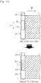
- winding is made such that the uncoated portions ( Fig. 10 ), which are not coated with the electrode active materials, respectively project on the opposite sides of the wound body surface. That is, winding is made such that the uncoated portions of the positive electrode foil 21 and the negative electrode foil 22 are respectively disposed at opposite ends in the winding axis direction (the width direction W) of the electrode body 20.
- the electrode body 20 may be a laminated body obtained by stacking layers of the positive electrode foil 21, the negative electrode foil 22, and the separator 23. In this case, the layers of the positive electrode foil 21, the negative electrode foil 22, and the separator 23 are stacked such that the uncoated portions of the positive electrode foil 21 and the negative electrode foil 22 project from the lateral sides of the laminated body.
- the positive electrode terminal 31 and the negative electrode terminal 32 are the electrode terminals of the sealed battery 7, and are respectively joined to the uncoated portions of the positive electrode foil 21 and the negative electrode foil 22, in the exterior 10. That is, the uncoated portions of the positive electrode foil 21 and the negative electrode foil 22 are used as the current collection portions of the electrode body 20, respectively.
- the sealed battery 7 is a lithium ion battery
- aluminium foil is used as the positive electrode foil 21, and copper foil is used as the negative electrode foil 22, for example.
- aluminium is used as the material of the positive electrode terminal 31, and copper is used as the material of the negative electrode terminal 32.
- the uncoated portion (current collection portion) of the positive electrode foil 21 and the positive electrode terminal 31 are joined together via the nugget (alloy layer) 5 formed by resistance heat generated from the resistance welding, by the use of the method for manufacturing the laminated metal foil.
- the nugget 5 is formed in an elliptical shape extending in the longitudinal direction L of the weld site A (nugget formation allowable region) to be joined with the positive electrode terminal 31, in the positive electrode foil 21.
- Fig. 9 illustrates the joining of the aluminium positive electrode foil 21 and the aluminium positive electrode terminal 31, the joining of the copper negative electrode foil 22 and the copper negative electrode terminal 32 is substantially the same as that shown in Fig. 9 .
- the positive electrode foil 21 is laid on the positive electrode terminal 31, a cover plate 51 is disposed on the outer surface on the positive electrode foil 21 side, and then, the cutter C is pressed whose longitudinal cross-sectional shape is substantially V-shape and which forms the linear notch 3 in a planar view, whereby the notch 3 is provided in the cover plate 51 and the positive electrode foil 21.
- the notch 3 is linearly provided at the center in the width direction W of the uncoated portion.
- the cover plate 51 is a protection member for avoiding direct contact between the positive electrode foil 21, and the pressing tool and the electrode E. By forming the notch 3, it is possible to partially remove the film of aluminium oxide present on the surface of the positive electrode foil 21.
- the site from which the oxide film has been removed has a lower resistance than the other site, and thus, can be used as the conduction portion R ( Fig. 5 ) through which current easily flows during the second step. Also in the copper negative electrode foil 22, the conduction portion R is formed in a similar manner.
- the depth of the notch 3 is set so that the notch 3 can penetrate the positive electrode foil 21 in the lamination direction S to form a protrusion which protrudes on the positive electrode terminal 31 side.
- the conduction portion R can be formed in the entire region in the lamination direction S of the positive electrode foil 21, and thus, it is possible to secure accurate energization in the second step. It is sufficient that the depth of the notch 3 is large enough to form a conduction portion having a resistance value lower than that of the other site in the positive electrode foil 21. For example, even when the depth of the notch 3 is set to be about 1/3 to 1/2 of the thickness of the positive electrode foil 21, a conduction path to be used during resistance welding can be made.
- the nugget 5 When the join has been made by means of the nugget 5, current from the electrode E preferentially flows through the periphery of the notch 3 having a smaller resistance value. As a result, the nugget 5 is formed so as to expand radially from the position where the notch 3 has been formed, and thus, the nugget 5 having an elliptical shape whose major axis extends in the longitudinal direction L of the electrode terminal 31 is formed.
- the battery capacity of the sealed battery 7 is dependent on the amount of the electrode active materials of the electrode body 20 being the power generating element. When a higher capacity of the sealed battery 7 is to be realized, it is required to increase the widths of the portions coated with the electrode active materials of the positive electrode foil 21 and the negative electrode foil 22, and to decrease the widths of the uncoated portions.
- an electrode body is formed in which the laminated metal foil is resistance-welded to the electrode terminals.
- the notch 3 is provided along the longitudinal direction L of the uncoated portion to secure the conduction portion R to be used during resistance welding, and then, the nugget 5 is formed to have an elliptical shape in accordance with the position where the notch 3 has been formed. Therefore, by using to the maximum the region where nugget formation is allowed, it is possible to secure a necessary area of the nugget even when the size in the width direction W of the uncoated portion is small, thereby to realize the joining through resistance welding. Accordingly, it is possible obtain a sealed battery having an increased area of the power generating region by reducing to the minimum the width of the uncoated portion, and thus, it is possible to improve the battery capacity efficiency.
- a thickness dimension t of each of the aluminium foil and the copper foil which are the metal foils is set as 10 ⁇ m ⁇ t ⁇ 50 ⁇ m, for example.
- the thickness dimension t is t ⁇ 10 ⁇ m
- the amount of the metal necessary in manufacture of the battery having a predetermined battery capacity increases, which is wasteful.
- the number of layers of each metal foil to be laminated can be increased or decreased as necessary.
- energization may be performed by applying minute current between the cutter C and the electrode E. That is, the first step may be performed as a primary welding step and the second step may be performed as a secondary welding step, whereby a two-stage welding step may be performed.
- the oxide film present on the surface of the positive electrode foil 21 is partially removed by the use of the cutter C, current flows between the cutter C and the electrode E, whereby the portion surrounding the cutter C is melted by Joule heat generated from the energization, and a molten-solidification portion is temporarily formed. Accordingly, a conduction portion which allows current to further easily flow therethrough can be made around the site where the notch 3 is formed.
- the area of the nugget 5 in the sealed battery 7 is set so as to secure a joining strength that prevents unjoining of the joined parts in the electrode body 20 when the electrode body 20 is to be housed in the exterior 10, for example.
- the shape of the nugget 5 can be changed depending on the number of the notches 3 to be formed, the place where the notch 3 is to be formed, and the like, and can be set as appropriate so as to secure the sufficient area of the nugget. That is, the number of the notches 3 to be formed, and the like may be determined such that the appropriate area of the nugget can be secured. Formation of the notch 3 by means of the cutter C performed from the positive electrode terminal 31 side exhibits the same effects as those described above.
- a manufacturing process of the sealed battery 7 includes: an electrode body manufacturing step; a cap SUB-ASSY manufacturing step including a laminated metal foil manufacturing step; and post-steps such as an exterior welding step, an electrolytic solution pouring step, an initial charge step, an aging step, and the like. Through these steps, the sealed battery 7 is manufactured as a product. Steps other than the laminated metal foil manufacturing step described here are realized by the use of well-known technology, and thus, detailed description thereof is omitted.
- the sealed battery 7 obtained through the manufacturing process of the sealed battery as described above it is possible to increase the widths of the portions coated with the electrode active materials in the electrode body 20, and to realize higher capacity of the battery.
- the laminated metal foil is used as the electrode body of the sealed battery.
- the laminated layers of the copper foil may be resistance-welded to each other, to be used for a capacitor or the like.
Landscapes
- Engineering & Computer Science (AREA)
- Mechanical Engineering (AREA)
- Chemical & Material Sciences (AREA)
- Connection Of Batteries Or Terminals (AREA)
- Materials Engineering (AREA)
- Chemical Kinetics & Catalysis (AREA)
- Electrochemistry (AREA)
- General Chemical & Material Sciences (AREA)
- Manufacturing & Machinery (AREA)
- Composite Materials (AREA)
Claims (2)
- Verfahren zur Herstellung einer versiegelten Batterie (7), wobei das Verfahren durch die folgenden Schritte gekennzeichnet ist:einen ersten Schritt des Bildens, an einer Schweißstelle von geschichteten Schichten einer Metallfolie (2), unter Verwendung eines Schneidwerkzeugs, dessen Längsquerschnittsform im Wesentlichen V-förmig ist, einer Einkerbung (3), die in einer Draufsicht linear ist und die geschichteten Schichten der Metallfolie (2) in einer Schichtungsrichtung davon durchschneidet, um zu bewirken, dass die geschichteten Schichten der Metallfolie entlang der Schichtungsrichtung an Enden einer linearen Einkerbung (3) aneinander haften; undeinen zweiten Schritt des Presskontaktierens einer Elektrode (E) zum Widerstandsschweißen mit einem Elektrodenanschluss (4), in einem Zustand, in dem der Elektrodenanschluss an der Schweißstelle (A) der geschichteten Schichten der Metallfolie ferner beschichtet ist, und anschließendes Widerstandsschweißen des Elektrodenanschlusses zusammen mit den geschichteten Schichten der Metallfolie, um die Schweißstelle und den Elektrodenanschluss über die Elektrode unter Strom zu setzen, wobeidie geschichteten Schichten der Metallfolie (2) eine Vielzahl von geschichteten Schichten aus einer Aluminiumfolie und einer Kupferfolie beinhalten,
die geschichteten Schichten der Aluminiumfolie als eine Positivelektrodenfolie (21) dienen, die in der versiegelten Batterie (7) enthalten ist, und wobei der Elektrodenanschluss ein Positivelektrodenanschluss ist, der in der versiegelten Batterie enthalten ist,die geschichteten Schichten der Kupferfolie als eine Negativelektrodenfolie (22) dienen, die in der versiegelten Batterie (7) enthalten ist, und wobei der Elektrodenanschluss ein Negativelektrodenanschluss ist, der in der versiegelten Batterie enthalten ist, undder zweite Schritt ein Zusammenfügen des Elektrodenanschlusses (4) mit den geschichteten Schichten der Metallfolie (2) durch Bilden einer Schweißlinse (5), welche eine elliptische Form aufweist und die sich in einer Längsrichtung des Elektrodenanschlusses erstreckende lineare Einkerbung, die unter Verwendung des Schneidwerkzeugs erzeugt wurde, umgibt. - Verfahren zur Herstellung der versiegelten Batterie (7) nach Anspruch 1, wobei
die Kupferfolie (22) eine elektrolytische Kupferfolie ist.
Applications Claiming Priority (2)
| Application Number | Priority Date | Filing Date | Title |
|---|---|---|---|
| JP2013005432A JP6088254B2 (ja) | 2012-01-17 | 2013-01-16 | 積層金属箔の製造方法およびこれを含む密閉型電池の製造方法 |
| PCT/JP2013/069267 WO2014112141A1 (ja) | 2013-01-16 | 2013-07-16 | 積層金属箔の製造方法およびこれを含む密閉型電池の製造方法、並びに密閉型電池 |
Publications (3)
| Publication Number | Publication Date |
|---|---|
| EP2946868A1 EP2946868A1 (de) | 2015-11-25 |
| EP2946868A4 EP2946868A4 (de) | 2016-09-28 |
| EP2946868B1 true EP2946868B1 (de) | 2018-04-11 |
Family
ID=51210863
Family Applications (1)
| Application Number | Title | Priority Date | Filing Date |
|---|---|---|---|
| EP13871543.8A Active EP2946868B1 (de) | 2013-01-16 | 2013-07-16 | Verfahren zur herstellung einer versiegelten batterie |
Country Status (4)
| Country | Link |
|---|---|
| EP (1) | EP2946868B1 (de) |
| KR (1) | KR102060027B1 (de) |
| CN (1) | CN104981316B (de) |
| WO (1) | WO2014112141A1 (de) |
Families Citing this family (6)
| Publication number | Priority date | Publication date | Assignee | Title |
|---|---|---|---|---|
| WO2018043739A1 (ja) | 2016-09-05 | 2018-03-08 | ナグシステム株式会社 | 積層金属箔の製造方法 |
| CN110291661B (zh) * | 2017-02-22 | 2022-06-17 | 远景Aesc日本有限公司 | 锂离子电池 |
| US20200343517A1 (en) * | 2019-04-23 | 2020-10-29 | Tiveni MergeCo Inc. | Multi-layer contact plate and method thereof |
| JP7245146B2 (ja) * | 2019-10-28 | 2023-03-23 | ニチコン株式会社 | リードタブと電極箔の接続方法、および巻回型蓄電素子の製造方法 |
| DE102020101087A1 (de) | 2020-01-17 | 2021-07-22 | Volkswagen Aktiengesellschaft | Verfahren und Vorrichtung zum Verbinden von Metallverbundfolien für Pouchzellen mit einem Vorsiegelband |
| CN116921829B (zh) * | 2023-09-07 | 2024-12-20 | 中创新航科技集团股份有限公司 | 一种电阻焊装置及集流体组件的电阻焊方法 |
Family Cites Families (10)
| Publication number | Priority date | Publication date | Assignee | Title |
|---|---|---|---|---|
| JPS58181487A (ja) * | 1982-04-16 | 1983-10-24 | Toyota Motor Corp | 積層部材のスポツト溶接方法 |
| JPS59202188A (ja) * | 1983-05-04 | 1984-11-15 | Toyota Motor Corp | 積層板の抵抗溶接方法 |
| JPS6456541A (en) * | 1987-08-28 | 1989-03-03 | Sumitomo Metal Ind | Manufacture of laminated steel sheet superior in resistance weldability |
| JP4835025B2 (ja) * | 2005-04-14 | 2011-12-14 | トヨタ自動車株式会社 | 蓄電装置の製造方法 |
| JP4206400B2 (ja) | 2005-05-25 | 2009-01-07 | ナグシステム株式会社 | 積層したアルミニウム箔の抵抗溶接方法 |
| JP4635978B2 (ja) * | 2006-08-02 | 2011-02-23 | ソニー株式会社 | 負極及び二次電池 |
| US7834292B2 (en) * | 2006-10-11 | 2010-11-16 | Gm Global Technology Operations, Inc. | Method for single side welding of laminate steel |
| KR100832343B1 (ko) * | 2007-05-23 | 2008-05-26 | 주식회사 포스코 | 박판 심용접 장치 |
| US8632910B2 (en) * | 2008-09-03 | 2014-01-21 | Samsung Sdi Co., Ltd. | Protection circuit board, secondary battery and battery pack |
| DE102009035495A1 (de) * | 2009-07-31 | 2011-02-03 | Daimler Ag | Batterie mit einem Stapel von bipolaren Batterieeinzelzellen |
-
2013
- 2013-07-16 KR KR1020157021575A patent/KR102060027B1/ko active Active
- 2013-07-16 CN CN201380070367.4A patent/CN104981316B/zh active Active
- 2013-07-16 EP EP13871543.8A patent/EP2946868B1/de active Active
- 2013-07-16 WO PCT/JP2013/069267 patent/WO2014112141A1/ja not_active Ceased
Non-Patent Citations (1)
| Title |
|---|
| None * |
Also Published As
| Publication number | Publication date |
|---|---|
| CN104981316A (zh) | 2015-10-14 |
| KR20150106913A (ko) | 2015-09-22 |
| EP2946868A1 (de) | 2015-11-25 |
| KR102060027B1 (ko) | 2019-12-27 |
| WO2014112141A1 (ja) | 2014-07-24 |
| EP2946868A4 (de) | 2016-09-28 |
| CN104981316B (zh) | 2018-02-27 |
Similar Documents
| Publication | Publication Date | Title |
|---|---|---|
| EP2293367B1 (de) | Wiederaufladbare Sekundärbatterie mit verbesserter Sicherheit bei Nagel- und Impakttest | |
| JP6505859B2 (ja) | 非水電解液二次電池 | |
| US10181594B2 (en) | Method for manufacturing stacked metal foil, method for manufacturing sealed cell including said method, and sealed cell | |
| EP2946868B1 (de) | Verfahren zur herstellung einer versiegelten batterie | |
| EP3508299B1 (de) | Verfahren zur herstellung einer laminierten metallfolie | |
| CN102044701A (zh) | 电池组及制造电池组的方法 | |
| CN113439350B (zh) | 电极板及其制造方法、二次电池及其制造方法 | |
| JP5876380B2 (ja) | 積層アルミニウム材の製造方法及びそれを含む密閉型電池の製造方法 | |
| CN108604505A (zh) | 蓄电设备及其制造方法 | |
| JP2020004643A (ja) | 蓄電装置 | |
| US10608233B2 (en) | Method of manufacturing secondary battery | |
| WO2020137714A1 (ja) | 二次電池 | |
| JP2014022153A (ja) | 蓄電装置 | |
| WO2020129999A1 (ja) | 二次電池用の電極板及びそれを用いた二次電池 | |
| CN111261832A (zh) | 二次电池及其制造方法 | |
| JP2001283897A (ja) | 電池及びその製造方法 | |
| JP4428965B2 (ja) | 電池ユニット | |
| JP2007273193A (ja) | 電気化学デバイス | |
| JP2014056672A (ja) | 蓄電装置、及び蓄電装置の製造方法 | |
| EP4148756A1 (de) | Stromspeichervorrichtung und verfahren zur herstellung der stromspeichervorrichtung | |
| US10468657B2 (en) | Electrical storage device and manufacturing method for electrical storage device | |
| WO2020137715A1 (ja) | 電極板及びそれを用いた二次電池 | |
| JP2014170614A (ja) | 電気化学素子用電極板および電気化学素子 | |
| WO2020130000A1 (ja) | 二次電池用の電極板及びそれを用いた二次電池 | |
| JP2014093150A (ja) | 蓄電装置 |
Legal Events
| Date | Code | Title | Description |
|---|---|---|---|
| PUAI | Public reference made under article 153(3) epc to a published international application that has entered the european phase |
Free format text: ORIGINAL CODE: 0009012 |
|
| 17P | Request for examination filed |
Effective date: 20150715 |
|
| AK | Designated contracting states |
Kind code of ref document: A1 Designated state(s): AL AT BE BG CH CY CZ DE DK EE ES FI FR GB GR HR HU IE IS IT LI LT LU LV MC MK MT NL NO PL PT RO RS SE SI SK SM TR |
|
| AX | Request for extension of the european patent |
Extension state: BA ME |
|
| DAX | Request for extension of the european patent (deleted) | ||
| A4 | Supplementary search report drawn up and despatched |
Effective date: 20160829 |
|
| RIC1 | Information provided on ipc code assigned before grant |
Ipc: B23K 11/34 20060101ALI20160823BHEP Ipc: B23K 103/12 20060101ALN20160823BHEP Ipc: B23K 11/00 20060101ALI20160823BHEP Ipc: B23K 103/18 20060101ALN20160823BHEP Ipc: B23K 11/11 20060101AFI20160823BHEP Ipc: B23K 103/10 20060101ALN20160823BHEP Ipc: B23K 11/18 20060101ALI20160823BHEP Ipc: H01M 2/26 20060101ALI20160823BHEP Ipc: H01M 10/0525 20100101ALI20160823BHEP |
|
| GRAP | Despatch of communication of intention to grant a patent |
Free format text: ORIGINAL CODE: EPIDOSNIGR1 |
|
| RIC1 | Information provided on ipc code assigned before grant |
Ipc: B23K 103/18 20060101ALN20170721BHEP Ipc: H01M 2/26 20060101ALI20170721BHEP Ipc: H01M 10/0525 20100101ALI20170721BHEP Ipc: B23K 11/00 20060101ALI20170721BHEP Ipc: B23K 11/11 20060101AFI20170721BHEP Ipc: B23K 103/12 20060101ALN20170721BHEP Ipc: B23K 11/18 20060101ALI20170721BHEP Ipc: B23K 103/10 20060101ALN20170721BHEP Ipc: B23K 11/34 20060101ALI20170721BHEP |
|
| INTG | Intention to grant announced |
Effective date: 20170821 |
|
| GRAJ | Information related to disapproval of communication of intention to grant by the applicant or resumption of examination proceedings by the epo deleted |
Free format text: ORIGINAL CODE: EPIDOSDIGR1 |
|
| INTC | Intention to grant announced (deleted) | ||
| RIC1 | Information provided on ipc code assigned before grant |
Ipc: B23K 11/00 20060101ALI20171221BHEP Ipc: H01M 10/0525 20100101ALI20171221BHEP Ipc: B23K 11/34 20060101ALI20171221BHEP Ipc: B23K 103/18 20060101ALN20171221BHEP Ipc: B23K 11/18 20060101ALI20171221BHEP Ipc: B23K 11/11 20060101AFI20171221BHEP Ipc: B23K 103/12 20060101ALN20171221BHEP Ipc: H01M 2/26 20060101ALI20171221BHEP Ipc: B23K 103/10 20060101ALN20171221BHEP |
|
| GRAR | Information related to intention to grant a patent recorded |
Free format text: ORIGINAL CODE: EPIDOSNIGR71 |
|
| GRAS | Grant fee paid |
Free format text: ORIGINAL CODE: EPIDOSNIGR3 |
|
| GRAA | (expected) grant |
Free format text: ORIGINAL CODE: 0009210 |
|
| INTG | Intention to grant announced |
Effective date: 20180228 |
|
| AK | Designated contracting states |
Kind code of ref document: B1 Designated state(s): AL AT BE BG CH CY CZ DE DK EE ES FI FR GB GR HR HU IE IS IT LI LT LU LV MC MK MT NL NO PL PT RO RS SE SI SK SM TR |
|
| REG | Reference to a national code |
Ref country code: GB Ref legal event code: FG4D |
|
| REG | Reference to a national code |
Ref country code: CH Ref legal event code: EP |
|
| REG | Reference to a national code |
Ref country code: AT Ref legal event code: REF Ref document number: 987472 Country of ref document: AT Kind code of ref document: T Effective date: 20180415 |
|
| REG | Reference to a national code |
Ref country code: IE Ref legal event code: FG4D |
|
| REG | Reference to a national code |
Ref country code: DE Ref legal event code: R096 Ref document number: 602013035916 Country of ref document: DE |
|
| REG | Reference to a national code |
Ref country code: NL Ref legal event code: FP |
|
| REG | Reference to a national code |
Ref country code: FR Ref legal event code: PLFP Year of fee payment: 6 |
|
| REG | Reference to a national code |
Ref country code: LT Ref legal event code: MG4D |
|
| PG25 | Lapsed in a contracting state [announced via postgrant information from national office to epo] |
Ref country code: FI Free format text: LAPSE BECAUSE OF FAILURE TO SUBMIT A TRANSLATION OF THE DESCRIPTION OR TO PAY THE FEE WITHIN THE PRESCRIBED TIME-LIMIT Effective date: 20180411 Ref country code: NO Free format text: LAPSE BECAUSE OF FAILURE TO SUBMIT A TRANSLATION OF THE DESCRIPTION OR TO PAY THE FEE WITHIN THE PRESCRIBED TIME-LIMIT Effective date: 20180711 Ref country code: BG Free format text: LAPSE BECAUSE OF FAILURE TO SUBMIT A TRANSLATION OF THE DESCRIPTION OR TO PAY THE FEE WITHIN THE PRESCRIBED TIME-LIMIT Effective date: 20180711 Ref country code: AL Free format text: LAPSE BECAUSE OF FAILURE TO SUBMIT A TRANSLATION OF THE DESCRIPTION OR TO PAY THE FEE WITHIN THE PRESCRIBED TIME-LIMIT Effective date: 20180411 Ref country code: SE Free format text: LAPSE BECAUSE OF FAILURE TO SUBMIT A TRANSLATION OF THE DESCRIPTION OR TO PAY THE FEE WITHIN THE PRESCRIBED TIME-LIMIT Effective date: 20180411 Ref country code: LT Free format text: LAPSE BECAUSE OF FAILURE TO SUBMIT A TRANSLATION OF THE DESCRIPTION OR TO PAY THE FEE WITHIN THE PRESCRIBED TIME-LIMIT Effective date: 20180411 Ref country code: PL Free format text: LAPSE BECAUSE OF FAILURE TO SUBMIT A TRANSLATION OF THE DESCRIPTION OR TO PAY THE FEE WITHIN THE PRESCRIBED TIME-LIMIT Effective date: 20180411 Ref country code: ES Free format text: LAPSE BECAUSE OF FAILURE TO SUBMIT A TRANSLATION OF THE DESCRIPTION OR TO PAY THE FEE WITHIN THE PRESCRIBED TIME-LIMIT Effective date: 20180411 |
|
| PG25 | Lapsed in a contracting state [announced via postgrant information from national office to epo] |
Ref country code: LV Free format text: LAPSE BECAUSE OF FAILURE TO SUBMIT A TRANSLATION OF THE DESCRIPTION OR TO PAY THE FEE WITHIN THE PRESCRIBED TIME-LIMIT Effective date: 20180411 Ref country code: GR Free format text: LAPSE BECAUSE OF FAILURE TO SUBMIT A TRANSLATION OF THE DESCRIPTION OR TO PAY THE FEE WITHIN THE PRESCRIBED TIME-LIMIT Effective date: 20180712 Ref country code: HR Free format text: LAPSE BECAUSE OF FAILURE TO SUBMIT A TRANSLATION OF THE DESCRIPTION OR TO PAY THE FEE WITHIN THE PRESCRIBED TIME-LIMIT Effective date: 20180411 Ref country code: RS Free format text: LAPSE BECAUSE OF FAILURE TO SUBMIT A TRANSLATION OF THE DESCRIPTION OR TO PAY THE FEE WITHIN THE PRESCRIBED TIME-LIMIT Effective date: 20180411 |
|
| REG | Reference to a national code |
Ref country code: AT Ref legal event code: MK05 Ref document number: 987472 Country of ref document: AT Kind code of ref document: T Effective date: 20180411 |
|
| PG25 | Lapsed in a contracting state [announced via postgrant information from national office to epo] |
Ref country code: PT Free format text: LAPSE BECAUSE OF FAILURE TO SUBMIT A TRANSLATION OF THE DESCRIPTION OR TO PAY THE FEE WITHIN THE PRESCRIBED TIME-LIMIT Effective date: 20180813 |
|
| REG | Reference to a national code |
Ref country code: DE Ref legal event code: R097 Ref document number: 602013035916 Country of ref document: DE |
|
| PG25 | Lapsed in a contracting state [announced via postgrant information from national office to epo] |
Ref country code: EE Free format text: LAPSE BECAUSE OF FAILURE TO SUBMIT A TRANSLATION OF THE DESCRIPTION OR TO PAY THE FEE WITHIN THE PRESCRIBED TIME-LIMIT Effective date: 20180411 Ref country code: DK Free format text: LAPSE BECAUSE OF FAILURE TO SUBMIT A TRANSLATION OF THE DESCRIPTION OR TO PAY THE FEE WITHIN THE PRESCRIBED TIME-LIMIT Effective date: 20180411 Ref country code: AT Free format text: LAPSE BECAUSE OF FAILURE TO SUBMIT A TRANSLATION OF THE DESCRIPTION OR TO PAY THE FEE WITHIN THE PRESCRIBED TIME-LIMIT Effective date: 20180411 Ref country code: RO Free format text: LAPSE BECAUSE OF FAILURE TO SUBMIT A TRANSLATION OF THE DESCRIPTION OR TO PAY THE FEE WITHIN THE PRESCRIBED TIME-LIMIT Effective date: 20180411 Ref country code: CZ Free format text: LAPSE BECAUSE OF FAILURE TO SUBMIT A TRANSLATION OF THE DESCRIPTION OR TO PAY THE FEE WITHIN THE PRESCRIBED TIME-LIMIT Effective date: 20180411 Ref country code: SK Free format text: LAPSE BECAUSE OF FAILURE TO SUBMIT A TRANSLATION OF THE DESCRIPTION OR TO PAY THE FEE WITHIN THE PRESCRIBED TIME-LIMIT Effective date: 20180411 |
|
| PLBE | No opposition filed within time limit |
Free format text: ORIGINAL CODE: 0009261 |
|
| STAA | Information on the status of an ep patent application or granted ep patent |
Free format text: STATUS: NO OPPOSITION FILED WITHIN TIME LIMIT |
|
| PG25 | Lapsed in a contracting state [announced via postgrant information from national office to epo] |
Ref country code: SM Free format text: LAPSE BECAUSE OF FAILURE TO SUBMIT A TRANSLATION OF THE DESCRIPTION OR TO PAY THE FEE WITHIN THE PRESCRIBED TIME-LIMIT Effective date: 20180411 Ref country code: IT Free format text: LAPSE BECAUSE OF FAILURE TO SUBMIT A TRANSLATION OF THE DESCRIPTION OR TO PAY THE FEE WITHIN THE PRESCRIBED TIME-LIMIT Effective date: 20180411 |
|
| REG | Reference to a national code |
Ref country code: CH Ref legal event code: PL |
|
| 26N | No opposition filed |
Effective date: 20190114 |
|
| PG25 | Lapsed in a contracting state [announced via postgrant information from national office to epo] |
Ref country code: LU Free format text: LAPSE BECAUSE OF NON-PAYMENT OF DUE FEES Effective date: 20180716 Ref country code: MC Free format text: LAPSE BECAUSE OF FAILURE TO SUBMIT A TRANSLATION OF THE DESCRIPTION OR TO PAY THE FEE WITHIN THE PRESCRIBED TIME-LIMIT Effective date: 20180411 |
|
| REG | Reference to a national code |
Ref country code: BE Ref legal event code: MM Effective date: 20180731 |
|
| REG | Reference to a national code |
Ref country code: IE Ref legal event code: MM4A |
|
| PG25 | Lapsed in a contracting state [announced via postgrant information from national office to epo] |
Ref country code: IE Free format text: LAPSE BECAUSE OF NON-PAYMENT OF DUE FEES Effective date: 20180716 Ref country code: CH Free format text: LAPSE BECAUSE OF NON-PAYMENT OF DUE FEES Effective date: 20180731 Ref country code: LI Free format text: LAPSE BECAUSE OF NON-PAYMENT OF DUE FEES Effective date: 20180731 |
|
| PG25 | Lapsed in a contracting state [announced via postgrant information from national office to epo] |
Ref country code: SI Free format text: LAPSE BECAUSE OF FAILURE TO SUBMIT A TRANSLATION OF THE DESCRIPTION OR TO PAY THE FEE WITHIN THE PRESCRIBED TIME-LIMIT Effective date: 20180411 Ref country code: BE Free format text: LAPSE BECAUSE OF NON-PAYMENT OF DUE FEES Effective date: 20180731 |
|
| PG25 | Lapsed in a contracting state [announced via postgrant information from national office to epo] |
Ref country code: MT Free format text: LAPSE BECAUSE OF NON-PAYMENT OF DUE FEES Effective date: 20180716 |
|
| PG25 | Lapsed in a contracting state [announced via postgrant information from national office to epo] |
Ref country code: TR Free format text: LAPSE BECAUSE OF FAILURE TO SUBMIT A TRANSLATION OF THE DESCRIPTION OR TO PAY THE FEE WITHIN THE PRESCRIBED TIME-LIMIT Effective date: 20180411 |
|
| PG25 | Lapsed in a contracting state [announced via postgrant information from national office to epo] |
Ref country code: HU Free format text: LAPSE BECAUSE OF FAILURE TO SUBMIT A TRANSLATION OF THE DESCRIPTION OR TO PAY THE FEE WITHIN THE PRESCRIBED TIME-LIMIT; INVALID AB INITIO Effective date: 20130716 Ref country code: MK Free format text: LAPSE BECAUSE OF NON-PAYMENT OF DUE FEES Effective date: 20180411 Ref country code: CY Free format text: LAPSE BECAUSE OF FAILURE TO SUBMIT A TRANSLATION OF THE DESCRIPTION OR TO PAY THE FEE WITHIN THE PRESCRIBED TIME-LIMIT Effective date: 20180411 |
|
| PG25 | Lapsed in a contracting state [announced via postgrant information from national office to epo] |
Ref country code: IS Free format text: LAPSE BECAUSE OF FAILURE TO SUBMIT A TRANSLATION OF THE DESCRIPTION OR TO PAY THE FEE WITHIN THE PRESCRIBED TIME-LIMIT Effective date: 20180811 |
|
| PGFP | Annual fee paid to national office [announced via postgrant information from national office to epo] |
Ref country code: NL Payment date: 20250717 Year of fee payment: 13 |
|
| PGFP | Annual fee paid to national office [announced via postgrant information from national office to epo] |
Ref country code: DE Payment date: 20250728 Year of fee payment: 13 |
|
| PGFP | Annual fee paid to national office [announced via postgrant information from national office to epo] |
Ref country code: GB Payment date: 20250716 Year of fee payment: 13 |
|
| PGFP | Annual fee paid to national office [announced via postgrant information from national office to epo] |
Ref country code: FR Payment date: 20250723 Year of fee payment: 13 |