EP2946884B1 - Bidirektionaler schraubenschlüssel - Google Patents
Bidirektionaler schraubenschlüssel Download PDFInfo
- Publication number
- EP2946884B1 EP2946884B1 EP13871817.6A EP13871817A EP2946884B1 EP 2946884 B1 EP2946884 B1 EP 2946884B1 EP 13871817 A EP13871817 A EP 13871817A EP 2946884 B1 EP2946884 B1 EP 2946884B1
- Authority
- EP
- European Patent Office
- Prior art keywords
- pawl
- ratchet surface
- spring
- gear
- pawl element
- Prior art date
- Legal status (The legal status is an assumption and is not a legal conclusion. Google has not performed a legal analysis and makes no representation as to the accuracy of the status listed.)
- Not-in-force
Links
Images




Classifications
-
- B—PERFORMING OPERATIONS; TRANSPORTING
- B25—HAND TOOLS; PORTABLE POWER-DRIVEN TOOLS; MANIPULATORS
- B25B—TOOLS OR BENCH DEVICES NOT OTHERWISE PROVIDED FOR, FOR FASTENING, CONNECTING, DISENGAGING, OR HOLDING
- B25B13/00—Spanners; Wrenches
- B25B13/46—Spanners; Wrenches of the ratchet type, for providing a free return stroke of the handle
- B25B13/461—Spanners; Wrenches of the ratchet type, for providing a free return stroke of the handle with concentric driving and driven member
- B25B13/462—Spanners; Wrenches of the ratchet type, for providing a free return stroke of the handle with concentric driving and driven member the ratchet parts engaging in a direction radial to the tool operating axis
- B25B13/465—Spanners; Wrenches of the ratchet type, for providing a free return stroke of the handle with concentric driving and driven member the ratchet parts engaging in a direction radial to the tool operating axis a pawl engaging an internally toothed ring
-
- B—PERFORMING OPERATIONS; TRANSPORTING
- B25—HAND TOOLS; PORTABLE POWER-DRIVEN TOOLS; MANIPULATORS
- B25B—TOOLS OR BENCH DEVICES NOT OTHERWISE PROVIDED FOR, FOR FASTENING, CONNECTING, DISENGAGING, OR HOLDING
- B25B17/00—Hand-driven gear-operated wrenches or screwdrivers
-
- B—PERFORMING OPERATIONS; TRANSPORTING
- B25—HAND TOOLS; PORTABLE POWER-DRIVEN TOOLS; MANIPULATORS
- B25B—TOOLS OR BENCH DEVICES NOT OTHERWISE PROVIDED FOR, FOR FASTENING, CONNECTING, DISENGAGING, OR HOLDING
- B25B23/00—Details of, or accessories for, spanners, wrenches, screwdrivers
- B25B23/0007—Connections or joints between tool parts
- B25B23/0035—Connection means between socket or screwdriver bit and tool
-
- B—PERFORMING OPERATIONS; TRANSPORTING
- B25—HAND TOOLS; PORTABLE POWER-DRIVEN TOOLS; MANIPULATORS
- B25B—TOOLS OR BENCH DEVICES NOT OTHERWISE PROVIDED FOR, FOR FASTENING, CONNECTING, DISENGAGING, OR HOLDING
- B25B13/00—Spanners; Wrenches
- B25B13/46—Spanners; Wrenches of the ratchet type, for providing a free return stroke of the handle
-
- B—PERFORMING OPERATIONS; TRANSPORTING
- B25—HAND TOOLS; PORTABLE POWER-DRIVEN TOOLS; MANIPULATORS
- B25B—TOOLS OR BENCH DEVICES NOT OTHERWISE PROVIDED FOR, FOR FASTENING, CONNECTING, DISENGAGING, OR HOLDING
- B25B15/00—Screwdrivers
- B25B15/02—Screwdrivers operated by rotating the handle
- B25B15/04—Screwdrivers operated by rotating the handle with ratchet action
Definitions
- the present invention relates to a hand tool, particularly to a bidirectional wrench.
- the hand's reversed rotation can be achieved by re-grasping the handle after releasing it, or by the tool which is equipped with an one-way means such as a ratchet surface to keep the main shaft stationary during the reversed rotation of the handle, or by re-inserting the tool bit to the screw after extracting the bit from engagement with the screw.
- the hand's reversed rotation could not bring any effective advance of the fastener, and therefore it becomes a wasted movement.
- U. S. Pat. No. 5,931,062 discloses a mechanical rectifier, which comprises a shaft; two driving element mounted on the shaft, each having a one-way clutch interposed between it and the shaft, with the clutches oriented in the same way on the shaft so that the shaft is always entrained in only one direction of rotation when either one of the two driving elements is rotated in that direction, and the shaft is overrun by a driving element that is rotated in the opposite direction; a rotation means positioned along the axis of the shaft and engaging a selected one of the driving elements; and a reversing mechanism coupling the two driving elements together and forcing them to always rotate in the opposite directions so that one driving element entrains the shaft and the other driving element overruns the shaft, thus causing the shaft to always turn in only one direction, regardless of the direction of rotation of the driving elements, so that transfers the bidirectional rotations of the rotation means (e.g.
- the mechanical rectifier can efficiently utilize the rotations of the rotation means in either way, i.e. no matter the handle rotates clockwise or anticlockwise, the shaft rotates in the same direction, therefore it can improve the efficiency of the hand motion, and save operation time.
- the converting mechanism of the invention can only make the shaft rotate in on direction, which could not meet the requirement of rotating the shaft in two directions, such as, tightening or loosening a fastener in the application of a torque wrench, the torque wrench equipped with the converting mechanism of the invention could only get the result of tightening a fastener (or loosening a fastener) no matter what operation it executes, either tightening or loosening a fastener, as the conventional wrenches do.
- WO 88/03999 A1 discloses a transmission which has unidirectional output rotation in response to multidirectional input rotation.
- the transmission comprises an output member and a reversing member.
- the reversing member is received in aperture of the output member.
- the reversing member has an integral head which extends from the circular plate away from the output member.
- WO 2013/004045 A1 discloses a bidirectional mechanical converting unit which comprises a main shaft, a driving mechanism which including a driving means and a reversing means, and a rotation means.
- the reversing means is sleeved on the main shaft.
- France Publication No. 2771667 A3 discloses a socket driving head which carries a connector to transmit the drive to the socket.
- a steel ball is fitted into the drive shaft of the connector and is fixed to secure the socket by a coupling rod, which passes through the hole in the screw and the corresponding hole in the connector.
- U.S. Publication No. US 2012/186400 A1 discloses a power tool which includes a motor having a motor drive shaft, a drive assembly, an output member and a first housing.
- the output assembly includes a single-pawl ratchet design.
- the technical object of the present invention is to provide a bidirectional wrench which can switch the rotation direction of the main shaft conveniently.
- the present invention provides a bidirectional wrench as defined in claim 1.
- one embodiment provides a bidirectional wrench, and comprises: a working part and a handle, the working part consisting of a main shaft, the main shaft being used to output torque and its axis being perpendicular to the handle; a capstan gear, a follower gear, an transmission seat and an idle gear, the capstan gear, the follower gear and the transmission seat being all mounted on the main shaft, the idle gear being mounted on the transmission seat and rotating between the capstan gear and the follower gear, wherein the handle entrains the capstan gear to rotate, and the transmission seat is equipped with a holding device, when holding the holding device and rotating the handle to entrain the capstan gear, the capstan gear entraining the follower gear to rotate reversely via the idle gear; a first ratchet surface rotating together with the capstan gear, and a second ratchet surface rotating together with the follower gear; a first pawl element and a second pawl element which are capable of driving the main shaft to rotate; wherein the first pawl element has
- the handle has a ring-shaped head, and the first ratchet surface is disposed on the inner circumference of the ring-shaped head.
- the first ratchet is disposed on the inner circumference of the capstan gear.
- the second ratchet is disposed on the inner circumference of the follower gear.
- the holding device is a holding ring.
- first pawl element and/or the second pawl element are/is fan-shaped.
- first pawl element and the second pawl element are mounted on the countershaft, the axis of the countershaft is parallel to but not overlap in the main shaft, and the countershaft engages with the main shaft and is capable of entraining the main shaft to rotate.
- the countershaft drills through the main shaft.
- the reversing switch further comprises a first spring-loaded plunger and a second spring-loaded plunger, the first spring-loaded plunger and the second spring-loaded plunger is fix on the newel in turn, and the first spring-loaded plunger and the second spring-loaded plunger matches with the first pawl element and the second pawl element respectively.
- springs are disposed inside the first spring-loaded plunger and the second spring-loaded plunger.
- the first pawl element matched with the first spring-loaded plunger has a first special shaped surface comprising a first concave section having a first side wall and a second side wall;
- the second pawl element matched with the second spring-loaded plunger has a second special shaped surface comprising a second concave section having a third side wall and a fourth side wall; under the first condition, the first spring-loaded plunger connects with the first side wall and the second spring-loaded plunger connects with the third side wall; under the second condition, the first spring-loaded plunger connects with the second side wall and the second spring-loaded plunger connects with the fourth side wall.
- the wrench comprises a knob and the newel comprises two ears arranged to be embedded into the knob, the knob being matched with the newel.
- the bidirectional wrench comprises a blocking device arranged to keep the bidirectional wrench on the working mode selected until being switched to other mode
- the blocking device comprises: a ball disposed between an output end of the main shaft and the newel; a groove, configured to be able to be matched with the ball, comprising a first groove and a second groove.
- the number of the idle gears is two, the idle gears mounted on an axis of the transmission seat that is perpendicular to the axis of the main shaft, wherein the idle gears respectively face to each other.
- capstan gear and the follower gear are face-gears, faces of the capstan gear and the follower gear being face to face, the idle gear being angle gears.
- the bidirectional wrench of the present invention achieves two working modes between which the wrench can convert conveniently.
- the input torque that the operator exerts is a clockwise torque or an anticlockwise torque
- the output torque of the output end of the bidirectional wrench of the present invention is a clockwise torque or an anticlockwise torque alternatively.
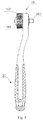
- the bidirectional wrench which refers to one detailed embodiment of the present invention, comprises a handle 20 and a working part 10, the handle 20 is socketed to the working part 10 across the ring-shaped head 21 (see Figure 3 ) through longitudinal extension.
- main shaft 100 Inside the working part 10 is main shaft 100, outside is a holding ring.
- One end of the main shaft is an output end 101 which extends beyond the working part 10 and the head 21 of the handle 20.
- the output end 101 can be a component, which is suitable to operate various fasteners like quoining screw, by mounting different sleeves.
- the bidirectional wrench of the present invention consists of a driving mechanism coupling with a reversing mechanism, the input torque from the handle 20 is transmitted to the main shaft 100 of the working part 10 through the driving mechanism, and make the direction of the output torque from the output end 101 be the first direction or the second direction, wherein the first direction and the second direction are opposite.
- the output torque of the output end 101 is a clockwise torque; or, when the input torque of the working part 10 is a clockwise torque or an anticlockwise torque, the output torque of the output end 101 is an anticlockwise torque.
- the structure of the driving mechanism of the bidirectional wrench of the present invention is shown in Figure 3 , consists of a first ratchet surface 311, a capstan gear 312, a second ratchet surface 321, a follower gear 322, a transmission seat 330, an idle gear 331 and 332.
- the first ratchet surface 311 and the capstan gear 312 connect and be coaxial with each other, in this embodiment, the first ratchet surface 311 is disposed in the inner circumference of the ring-shaped head 21 of the handle 20, the driving gear engages with the head 21 of the handle 20, thus the head 21 will drive driving gear to rotate when the handle 20 rotates, in other embodiment, the first ratchet surface 311 can be disposed in the inner circumference of capstan gear 312; the second ratchet surface 321 can be disposed in the inner circumference of follower gear 322.
- the faces of the first ratchet surface 311 and the second ratchet surface 321 connect with the outer face of the main shaft 100; the capstan gear 312 and the follower gear 322 are face-gears, faces of the capstan gear 312 and the follower gear 322 are face to face.
- the first ratchet 311, the second ratchet 321, the capstan gear 312 and the follower gear 322 are coaxial and the center axes thereof overlap in that of the main shaft 100.
- the transmission seat 330 and the holding ring 102 are fixed together.
- the idle gear 331, 332 are mounted on the transmission seat 330, which is perpendicular to the main shaft 100.
- the idle gear 331, 332 are matched between the capstan gear 312 and the follower gear 322, their tooth engage with the tooth of the capstan gear 312 and the follower gear 322 to drive respectively, when the holding ring 102 is fixed, or the transmission seat 330 is fixed, the capstan gear 312 will drive the follower gear 322 to rotate via the idle gear 331, 332.
- the idle gear 331, 332 are angle gears.
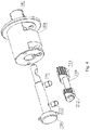
- the structure of the reversing mechanism of the bidirectional wrench of the present invention is shown in Figure 4 , comprises a newel, a reversing switch consisting of a first spring-loaded plunger 221 and a second spring-loaded plunger 222, a first pawl element 211 and a second pawl element 212.
- the newel 220 is fixed in the main shaft 100, the first spring-loaded plunger 221 and the second spring-loaded plunger 222 are fixed on the newel 220 in turn, the first spring-loaded plunger 221 and the second spring-loaded plunger 222 are perpendicular to the main shaft 100 along the active direction, preferably, the first spring-loaded plunger 221 and the second spring-loaded plunger 222 have elastic elements such as a spring.
- the first pawl element 211 and second pawl element 212 are fixed on the main shaft 100 across the countershaft 210, as shown in Figure 5 , the countershaft 210 is parallel to the center axis of the main shaft 100 but it does not overlap in it, the first pawl element 211 and the second pawl element 212 can rotate round the countershaft 210.
- the first pawl element 211 and the second pawl element 212 have a similar structure, namely a first fan-shaped pawl, a second fan-shaped pawl and a fan-shaped space between them.
- Figure 6 shows the top view of the first pawl element 211 (direction towards the output end 101 along the main shaft 100), as can be seen from Figure 6 , the first pawl element 211 consists of the first fan-shaped pawl 2111, the second fan-shaped pawl 2112 and the fan-shaped space between them.
- the fan-shaped face of the first fan-shaped pawl 2111, the fan-shaped space center section and the fan-shaped face of the second fan-shaped pawl 2112 constitutes the first surface of the first pawl element 211.
- the first pawl element 211 also has a second surface which is a special shaped surface and contains a concave section 2113, which has a first side wall 2114 and a second side wall 2115, in this embodiment.
- the first side wall 2114 and the second side wall 2115 extend along the main shaft 100.
- the first pawl element 211 has a hole 2101 which is matched with the countershaft 210, the countershaft 210 fixes the first pawl element 211 on the main shaft across the hole 2101 (see Figure 5 ).
- the hole 2101 is arranged on the fan-shaped center section of the first pawl element 211, preferably, on the center of gravity of the first pawl element 211.
- the structure of the second pawl element 212 is similar to the first pawl element 211, no more description, its thickness is less than that of the first pawl element 211 in this embodiment, but in other embodiments, its thickness can be equal to or more than that of the first pawl element 211.
- the first surface of the first pawl element 211 and the second pawl element 212 face to the first ratchet surface 311 and the second ratchet surface 321 respectively, specifically, the tooth of the fan-shaped pawl (which contains the first fan-shaped pawl 2111 and the second fan-shaped pawl 2112) of the first pawl element 211 face to the tooth of the first ratchet 311, the tooth of the fan-shaped pawl (contains the first fan-shaped pawl and the second fan-shaped pawl) of the second pawl element 212 face to the tooth of the second ratchet surface 321.
- the second surface of the first pawl element 211 and the second pawl element 212 face to the surface of the newel 220, specifically, the second surface of the first pawl element 211 faces to the ball-head section of the first spring-loaded plunger 221, the second surface of the second pawl element 212 faces to the ball-head section of the second spring-loaded plunger 222.
- the ball-head section of the first spring-loaded plunger 221 connects with the first side wall 2114 of the concave section 2113 of the first pawl element 211, the ball-head section of the second spring-loaded plunger 222 connects with the first side wall of the concave section of the second pawl element 212, when the bidirectional wrench of the present invention is on the first working mode; or, the ball-head section of the first spring-loaded plunger 221 connects with the second side wall 2115 of the concave section 2113 of the first pawl element 211, the ball-head section of the second spring-loaded plunger 222 connects with the second side wall of the concave section of the second pawl element 212, when the bidirectional wrench of the present invention is on the second working mode.
- the tooth of the first fan-shaped pawl 2111 of the first pawl element 211 connects with the tooth of the first ratchet surface 311, similarly, the tooth of the first fan-shaped pawl of the second pawl element 212 connects with the tooth of the second ratchet surface 321.
- the rotation direction of the second ratchet surface 321 is opposite to the first ratchet surface 311. It can be seen from this, when the bidirectional wrench of the present invention is on the first working mode, when the input torque from the working part 10 is a clockwise torque, it makes the first ratchet surface 311 rotate clockwise and the second ratchet surface 321 rotate anticlockwise, the first pawl element 211 does not engage with the first ratchet surface 311 and the second pawl element 212 engages with the second ratchet surface 321 at the moment, thus the second pawl element 212 drives the main shaft 100 to rotate anticlockwise and the output torque is an anticlockwise torque; when the input torque from the working part 10 is an anticlockwise torque, it makes the first ratchet 311 rotate anticlockwise and the second ratchet surface 321 rotate clockwise, the first pawl element 211 engages
- the tooth of the second fan-shaped pawl 2112 of the first pawl element 211 connects with the tooth of the first ratchet surface 311, similarly, the tooth of the second fan-shaped pawl of the second pawl element 212 connects with the tooth of the second ratchet surface 321.
- the head 21 of the handle 20 drives the first ratchet surface 311 to rotate
- the moving direction of the first ratchet surface 311 beside the second fan-shaped pawl 2112 is from the first fan-shaped section 2111 to the second fan-shaped section 2112, namely the first ratchet surface 311 rotates clockwise
- the first ratchet surface 311 can drive the first pawl element 211 to rotate, namely the tooth of the second fan-shaped pawl 2112 engages with the tooth of the first ratchet surface 311; and the rotation of the first pawl element 211 is transferred to the main shaft 100 through the countershaft 210, thus driving the main shaft 100 to rotate; but when the moving direction of the first ratchet surface 311 beside the second fan-shaped pawl 2112 is from the second fan-shaped section 2112 to the first fan-
- the moving direction of the second ratchet surface 321 beside the second fan-shaped pawl of the second pawl element 212 is from the first fan-shaped section to the second fan-shaped section in the second pawl element 212, namely the second ratchet surface 321 rotates clockwise
- the second ratchet surface 321 can drive the second pawl element 212 to rotate, namely the tooth of the second fan-shaped pawl of the second pawl element 212 engages with the tooth of the second ratchet surface 321; and the rotation of the second pawl element 212 is transferred to the main shaft 100 through the countershaft 210, thus driving the main shaft 100 to rotate.
- the rotation direction of the second ratchet surface 321 is opposite to the first ratchet surface 311. It can be seen from this, when the bidirectional wrench of the present invention is on the second working mode, when the input torque from the working part 10 is a clockwise torque, it makes the first ratchet surface 311 rotate clockwise and the second ratchet surface 321 rotate anticlockwise, the first pawl element 211 engages with the first ratchet surface 311 and the second pawl element 212 does not engage with the second ratchet surface 321 at the moment, thus the first pawl element 211 drives the main shaft 100 to rotate clockwise and the output torque is a clockwise torque; when the input torque from the working part 10 is an anticlockwise torque, it makes the first ratchet 311 rotate anticlockwise and the second ratchet surface 321 rotate clockwise, the first pawl element 211 does not engage with the
- the first working mode and the second working of the bidirectional wrench of the present invention can be switched and selected via the newel 220.
- the first end of the newel 220 has a knob 223, which would be matched with the newel 220 by embedding the two ears (ear 2201 in Figure 8 ) of the newel 220 into the knob 223.
- the newel 220 will rotate when turning the knob 223.
- two spines protrude out of the surface of the knob 223, such as spine 2231, turning of the knob 223 can be achieved by putting rotating torque on the two spines including the spine 2231.
- the bidirectional wrench of the present invention also contains a blocking device, which keeps the bidirectional wrench of the present invention on the working mode selected until the operator switch it to the other mode artificially.
- the blocking device in this embodiment consists of a ball 400 disposed between the output end 101 and the second end of the newel 220, a groove matched with the ball 400 on the second end of the newel 220, specifically, the first groove 410 and the second groove 420.
- the first groove 410 and the second groove 420 are parallel with each other and are separated by the smooth spine.
- the head working part of the first spring-loaded plunger 221 and the second spring-loaded plunger 222 keeps connecting with the first side wall of the concave section of the first pawl element 211 and the second pawl element 212 respectively, namely the first working mode of the bidirectional wrench of the present invention
- the head working part of the first spring-loaded plunger 221 and the second spring-loaded plunger 222 keeps connecting with the second side wall of the concave section of the first pawl element 211 and the second pawl element 212 respectively, namely the second working mode of the bidirectional wrench of the present invention.
- the bidirectional wrench of the present invention turns from the first working mode to the second working mode; when turning the knob 223 to rotate the newel 220 and let the ball 400 move from the second groove 420 to the first groove 410, the bidirectional wrench of the present invention turns from the second working mode to the first working mode.
- the transmission seat 330 engages with the holding ring 102 constantly, the transmission seat 330 is fixed with respect to the holding ring 102, thus when the working part 20 rotates with respect to the holding ring 102, the idle gear 331, 332 makes the follower gear 322 and the capstan 312 rotate in the opposite direction.
- the output end 101 of the bidirectional wrench of the present invention can be a component, which is suitable to operate various fasteners such as quoining screw, by mounting various sleeves, and the ball 400 in the blocking device can also be used to block the various sleeves which are mounted on the output end 101 at this moment.
Landscapes
- Engineering & Computer Science (AREA)
- Mechanical Engineering (AREA)
- Details Of Spanners, Wrenches, And Screw Drivers And Accessories (AREA)
- Transmission Devices (AREA)
Claims (15)
- Bidirektionaler Schraubenschlüssel, umfassend einen Arbeitsteil (10) und einen Griff (20), dadurch gekennzeichnet, dass der Arbeitsteil (10) Folgendes umfasst:eine Hauptwelle (100), die zum Ausgeben von Drehmoment verwendet wird und deren Achse senkrecht zum Griff (20) steht;ein Antriebszahnrad (312), ein Mitlaufzahnrad (322), einen Übersetzungssitz (330) und ein Zwischenrad (331, 332), wobei das Antriebszahnrad (312), das Mitlaufzahnrad (322) und der Übersetzungssitz (330) alle auf der Hauptwelle (100) angebracht sind und das Zwischenrad (331, 332) auf dem Übersetzungssitz (330) angebracht ist und sich zwischen dem Antriebszahnrad (312) und dem Mitlaufzahnrad (322) dreht, wobeider Griff (20) das Antriebszahnrad (312) mitnimmt, um es zu drehen, und der Übersetzungssitz (330) mit einer Haltevorrichtung ausgestattet ist, wobei das Antriebszahnrad (312), wenn die Haltevorrichtung gehalten wird und der Griff (20) gedreht wird, das Antriebszahnrad (312) das Mitlaufzahnrad (322) zum umgekehrten Drehen über das Zwischenrad (331, 332) mitnimmt;eine erste Sperrradoberfläche (311), die sich zusammen mit dem Antriebszahnrad (312) dreht, und eine zweite Sperrradoberfläche (321), die sich zusammen mit dem Mitlaufzahnrad (322) dreht;ein erstes Sperrklinkenelement (211) und ein zweites Sperrklinkenelement (212), die zum Antreiben der Hauptwelle (100) zur Drehung in der Lage sind; wobeidas erste Sperrklinkenelement (211) eine erste Sperrklinke (2111) und eine zweite Sperrklinke (2112) aufweist, die selektiv an die erste Sperrradoberfläche (311) angepasst sind, wobei die erste Sperrklinke (2111) in der ersten Richtung über die erste Sperrradoberfläche (311) gleitet, aber in der zweiten Richtung mit der ersten Sperrradoberfläche (311) eingreift, und die zweite Sperrklinke (2112) in der ersten Richtung mit der ersten Sperrradoberfläche (311) eingreift, aber in der zweiten Richtung über die erste Sperrradoberfläche (311) gleitet;das zweite Sperrklinkenelement (212) eine dritte Sperrklinke und eine vierte Sperrklinke aufweist, die selektiv an die zweite Sperrradoberfläche (321) angepasst sind, wobei die dritte Sperrklinke in der ersten Richtung über die zweite Sperrradoberfläche (321) gleitet, aber in der zweiten Richtung mit der zweiten Sperrradoberfläche (321) eingreift, und die vierte Sperrklinke in der ersten Richtung mit der zweiten Sperrradoberfläche (321) eingreift, aber in der zweiten Richtung über die zweite Sperrradoberfläche (321) gleitet;einen Umkehrschalter, der zum Versetzen des ersten Sperrklinkenelements (211) und des zweiten Sperrklinkenelements (212) in einen ersten Zustand und einen zweiten Zustand in der Lage ist, wobei die erste Sperrklinke (2111) und die dritte Sperrklinke im ersten Zustand an die erste Sperrradoberfläche (311) bzw. die zweite Sperrradoberfläche (321) angepasst sind; die zweite Sperrklinke (2112) und die vierte Sperrklinke im zweiten Zustand an die erste Sperrradoberfläche (311) bzw. die zweite Sperrradoberfläche (321) angepasst sind;wobei der Umkehrschalter eine Spindel (220) umfasst, wobei die Spindel (220) im Inneren der Hauptwelle (100) angeordnet ist; ein Ende der Hauptwelle (100) ein Ausgangsende (101) ist, das sich über einen Kopf (21) des Griffs (20) hinaus erstreckt;wobei die erste Richtung im Uhrzeigersinn oder gegen den Uhrzeigersinn ist und die zweite Richtung der ersten Richtung entgegengesetzt ist.
- Bidirektionaler Schraubenschlüssel nach Anspruch 1, wobei der Griff (20) einen ringförmigen Kopf (21) aufweist und die erste Sperrradoberfläche (311) auf dem Innenumfang des ringförmigen Kopfs (21) angeordnet ist.
- Bidirektionaler Schraubenschlüssel nach Anspruch 1, wobei die erste Sperrradoberfläche (311) auf dem Innenumfang des Antriebszahnrads (312) angeordnet ist.
- Bidirektionaler Schraubenschlüssel nach Anspruch 1, wobei die zweite Sperrradoberfläche (321) auf dem Innenumfang des Mitlaufzahnrads (322) angeordnet ist.
- Bidirektionaler Schraubenschlüssel nach Anspruch 1, wobei die Haltevorrichtung ein Haltering (102) ist.
- Bidirektionaler Schraubenschlüssel nach Anspruch 1, wobei das erste Sperrklinkenelement (211) und/oder das zweite Sperrklinkenelement (212) fächerförmig ist/sind.
- Bidirektionaler Schraubenschlüssel nach Anspruch 1, wobei das erste Sperrklinkenelement (211) und das zweite Sperrklinkenelement (212) auf der Zwischenwelle (210) angebracht sind, wobei die Achse der Zwischenwelle (210) parallel zur Hauptwelle (100) verläuft, diese aber nicht überlappt, und die Zwischenwelle (210) mit der Hauptwelle (100) in Eingriff steht und zum Mitnehmen der Hauptwelle (100) zur Drehung in der Lage ist.
- Bidirektionaler Schraubenschlüssel nach Anspruch 7, wobei die Zwischenwelle (210) die Hauptwelle (100) durchbohrt.
- Bidirektionaler Schraubenschlüssel nach Anspruch 1, wobei der Umkehrschalter ferner einen ersten federbelasteten Druckbolzen (221) und einen zweiten federbelasteten Druckbolzen (222) umfasst, wobei der erste federbelastete Druckbolzen (221) und der zweite federbelastete Druckbolzen (222) abwechselnd an der Spindel (220) fixiert sind und der erste federbelastete Druckbolzen (221) und der zweite federbelastete Druckbolzen (222) an das erste Sperrklinkenelement (211) bzw. das zweite Sperrklinkenelement (212) angepasst sind.
- Bidirektionaler Schraubenschlüssel nach Anspruch 9, wobei im Inneren des ersten federbelasteten Druckbolzens (221) und des zweiten federbelasteten Druckbolzens (222) Federn angeordnet sind.
- Bidirektionaler Schraubenschlüssel nach Anspruch 9, wobei
das erste Sperrklinkenelement (211), das an den ersten federbelasteten Druckbolzen (221) angepasst ist, eine erste speziell geformte Oberfläche aufweist, die einen konkaven Abschnitt (2113) mit einer ersten Seitenwand (2114) und einer zweiten Seitenwand (2115) umfasst;
das zweite Sperrklinkenelement (212), das an den zweiten federbelasteten Druckbolzen (222) angepasst ist, eine zweite speziell geformte Oberfläche aufweist, die einen zweiten konkaven Abschnitt mit einer dritten Seitenwand und einer vierten Seitenwand umfasst;
in dem ersten Zustand der erste federbelastete Druckbolzen (221) sich mit der ersten Seitenwand (2114) verbindet und der zweite federbelastete Druckbolzen (222) sich mit der dritten Seitenwand verbindet;
in dem zweiten Zustand der erste federbelastete Druckbolzen (221) sich mit der zweiten Seitenwand (2115) verbindet und der zweite federbelastete Druckbolzen (222) sich mit der vierten Seitenwand verbindet. - Bidirektionaler Schraubenschlüssel nach Anspruch 9, wobei der Schraubenschlüssel einen Knopf (223) umfasst und die Spindel (220) zwei Nasen (2201) umfasst, die so angeordnet sind, dass sie in dem Knopf (223) eingebettet sind, wobei der Knopf (223) an die Spindel (220) angepasst ist.
- Bidirektionaler Schraubenschlüssel nach Anspruch 1, wobei der bidirektionale Schraubenschlüssel eine Blockiervorrichtung umfasst, die angeordnet ist, um den bidirektionalen Schraubenschlüssel im ausgewählten Arbeitsmodus zu halten, bis in einen anderen Modus gewechselt wird, wobei die Blockiervorrichtung Folgendes umfasst:eine Kugel (400), die zwischen einem Ausgangsende (101) der Hauptwelle (100) und der Spindel (220) angeordnet ist;eine Nut, die konfiguriert ist, um zur Anpassung an die Kugel (400) in der Lage zu sein, umfassend einen erste Nut (410) und eine zweite Nut (420).
- Bidirektionaler Schraubenschlüssel nach Anspruch 1, wobei die Anzahl der Zwischenräder (331, 332) zwei beträgt, wobei die Zwischenräder (331, 332) auf einer Achse des Übersetzungssitzes (330) angebracht sind, die senkrecht zu der Achse der Hauptwelle (100) steht, wobei die Zwischenräder (331, 332) einander jeweils zugewandt sind.
- Bidirektionaler Schraubenschlüssel nach Anspruch 1, wobei das Antriebszahnrad (312) und das Mitlaufzahnrad (322) Zahnräder mit Stirnverzahnung sind, wobei Stirnseiten des Antriebszahnrads (312) und des Mitlaufzahnrads (322) einander gegenüberliegen, wobei die Zwischenräder (331, 332) Winkelräder sind.
Applications Claiming Priority (1)
| Application Number | Priority Date | Filing Date | Title |
|---|---|---|---|
| PCT/CN2013/070641 WO2014110776A1 (zh) | 2013-01-18 | 2013-01-18 | 双向扳手 |
Publications (3)
| Publication Number | Publication Date |
|---|---|
| EP2946884A1 EP2946884A1 (de) | 2015-11-25 |
| EP2946884A4 EP2946884A4 (de) | 2016-10-12 |
| EP2946884B1 true EP2946884B1 (de) | 2020-05-20 |
Family
ID=51208959
Family Applications (1)
| Application Number | Title | Priority Date | Filing Date |
|---|---|---|---|
| EP13871817.6A Not-in-force EP2946884B1 (de) | 2013-01-18 | 2013-01-18 | Bidirektionaler schraubenschlüssel |
Country Status (10)
| Country | Link |
|---|---|
| EP (1) | EP2946884B1 (de) |
| JP (1) | JP6224732B2 (de) |
| KR (1) | KR102019293B1 (de) |
| AU (1) | AU2013374087B2 (de) |
| BR (1) | BR112015017168B1 (de) |
| CA (1) | CA2898263C (de) |
| MX (1) | MX360127B (de) |
| NZ (1) | NZ711151A (de) |
| RU (1) | RU2628597C2 (de) |
| WO (1) | WO2014110776A1 (de) |
Families Citing this family (5)
| Publication number | Priority date | Publication date | Assignee | Title |
|---|---|---|---|---|
| US10399213B2 (en) | 2015-01-28 | 2019-09-03 | Hangzhou Great Star Tools Co., Ltd. | Adjustable wrench |
| KR101726547B1 (ko) | 2016-05-18 | 2017-04-12 | 김나영 | 다용도 라쳇렌치 |
| US11865678B2 (en) * | 2021-02-02 | 2024-01-09 | Snap-On Incorporated | Dual pawl ratchet mechanism |
| US11986928B2 (en) | 2022-04-14 | 2024-05-21 | Snap-On Incorporated | Pawl mechanism for ratchet tool |
| CN118342452B (zh) * | 2024-06-17 | 2024-08-13 | 山东祺月集团有限公司 | 一种儿童车装配用的手动工具 |
Citations (1)
| Publication number | Priority date | Publication date | Assignee | Title |
|---|---|---|---|---|
| US7587961B1 (en) * | 2008-08-11 | 2009-09-15 | William Tools Co., Ltd. | Reversible ratchet tool |
Family Cites Families (17)
| Publication number | Priority date | Publication date | Assignee | Title |
|---|---|---|---|---|
| CA1112913A (en) * | 1979-02-05 | 1981-11-24 | John Penner | Ratchet wrench of the socket drive type with socket ejector |
| JPH01502287A (ja) * | 1986-11-24 | 1989-08-10 | ウイリアムズ トーマス エー | 逆転可能な伝動装置 |
| US4802387A (en) * | 1986-11-24 | 1989-02-07 | Williams Thomas A Iii | Reversible unidirectional transmission |
| SU1466922A1 (ru) * | 1987-04-06 | 1989-03-23 | Предприятие П/Я Р-6670 | Резьбозавертывающий инструмент с приводом от гибкого вала |
| US5058463A (en) * | 1990-10-29 | 1991-10-22 | Midland Design Inc. | Ratchet wrench with dual-rotating constant drive handle |
| GB9426247D0 (en) * | 1994-12-24 | 1995-02-22 | Wisbey James H | Ratchet wrench |
| CN2248119Y (zh) * | 1995-07-04 | 1997-02-26 | 汤正汉 | 导线间隔棒扳手 |
| US5931062A (en) * | 1997-05-13 | 1999-08-03 | Marcovici; Mitch | Efficient mechanical rectifier |
| FR2771667B3 (fr) * | 1997-12-01 | 1999-10-29 | Chih Ching Hsieh | Cle a douille a cliquet |
| CN1202438A (zh) * | 1998-06-12 | 1998-12-23 | 贾俊英 | 自行车双向双速传动装置 |
| US6101901A (en) * | 1999-08-10 | 2000-08-15 | The Stanley Works | Dual-pawl full engagement reversible ratchet wrench |
| EP1341646A4 (de) * | 1999-11-23 | 2004-07-14 | Frederick L Zinck | Umkehrbare ratschenkopfanordnung |
| CN2485095Y (zh) * | 2001-06-06 | 2002-04-10 | 陈木林 | 一种棘轮扳手结构改良 |
| RU27799U1 (ru) * | 2002-11-12 | 2003-02-20 | Общество с ограниченной ответственностью "Контур-Аван" | Трещеточный гаечный ключ |
| US20060065080A1 (en) * | 2004-09-28 | 2006-03-30 | Davidson John B | Ratcheting tools |
| US9120213B2 (en) * | 2011-01-21 | 2015-09-01 | Milwaukee Electric Tool Corporation | Powered ratchet wrench |
| CN102862137A (zh) * | 2011-07-07 | 2013-01-09 | 杭州巨星工具有限公司 | 双向机械矫正器 |
-
2013
- 2013-01-18 MX MX2015009163A patent/MX360127B/es active IP Right Grant
- 2013-01-18 JP JP2015552965A patent/JP6224732B2/ja active Active
- 2013-01-18 EP EP13871817.6A patent/EP2946884B1/de not_active Not-in-force
- 2013-01-18 KR KR1020157022171A patent/KR102019293B1/ko active Active
- 2013-01-18 AU AU2013374087A patent/AU2013374087B2/en not_active Ceased
- 2013-01-18 CA CA2898263A patent/CA2898263C/en not_active Expired - Fee Related
- 2013-01-18 RU RU2015134541A patent/RU2628597C2/ru active
- 2013-01-18 BR BR112015017168-0A patent/BR112015017168B1/pt not_active IP Right Cessation
- 2013-01-18 NZ NZ711151A patent/NZ711151A/en not_active IP Right Cessation
- 2013-01-18 WO PCT/CN2013/070641 patent/WO2014110776A1/zh not_active Ceased
Patent Citations (1)
| Publication number | Priority date | Publication date | Assignee | Title |
|---|---|---|---|---|
| US7587961B1 (en) * | 2008-08-11 | 2009-09-15 | William Tools Co., Ltd. | Reversible ratchet tool |
Also Published As
| Publication number | Publication date |
|---|---|
| CA2898263C (en) | 2019-04-30 |
| KR102019293B1 (ko) | 2019-09-06 |
| MX360127B (es) | 2018-10-23 |
| JP2016503732A (ja) | 2016-02-08 |
| BR112015017168B1 (pt) | 2021-08-10 |
| EP2946884A4 (de) | 2016-10-12 |
| EP2946884A1 (de) | 2015-11-25 |
| AU2013374087A1 (en) | 2015-09-03 |
| BR112015017168A2 (pt) | 2017-07-11 |
| JP6224732B2 (ja) | 2017-11-01 |
| CA2898263A1 (en) | 2014-07-24 |
| MX2015009163A (es) | 2016-04-25 |
| KR20150107850A (ko) | 2015-09-23 |
| NZ711151A (en) | 2018-04-27 |
| RU2628597C2 (ru) | 2017-08-21 |
| WO2014110776A1 (zh) | 2014-07-24 |
| RU2015134541A (ru) | 2017-02-22 |
| AU2013374087B2 (en) | 2018-05-24 |
Similar Documents
| Publication | Publication Date | Title |
|---|---|---|
| EP2998069B1 (de) | Elektrischer Ratschenschlüssel | |
| US9802298B2 (en) | Electric ratchet wrench | |
| TWI571360B (zh) | Electric sleeve ratchet wrench | |
| EP2946884B1 (de) | Bidirektionaler schraubenschlüssel | |
| US20180236641A1 (en) | Electric Socket Ratchet Wrench and Method of Using the Same | |
| US20140116205A1 (en) | Bidirectional Mechanical Converting Unit | |
| EP3100825B1 (de) | Elektrischer ratschenschlüssel | |
| US20140274548A1 (en) | Clutch for power tool | |
| CN203045591U (zh) | 双向扳手 | |
| KR980700900A (ko) | 미늘톱니렌치(ratchet wrench) | |
| JP2019515809A (ja) | 動力駆動ダイレクト・ドライブ・ラチェット/レンチ工具 | |
| US9643297B2 (en) | Bi-directional wrench | |
| US8707831B2 (en) | Dual-drive, self-ratcheting mechanism | |
| CN105328622B (zh) | 棘轮工具 | |
| CA2952889C (en) | Thin bidirection ratchet wrench | |
| CN103934776B (zh) | 双向扳手 | |
| JP6461274B2 (ja) | 双方向レンチ | |
| CN105328611A (zh) | 薄型双向棘轮扳手 | |
| US9333630B2 (en) | Dual-drive, self-ratcheting, mechanism with multiple input ports | |
| CN204076103U (zh) | 薄型双向棘轮扳手 | |
| CN221160153U (zh) | 一种双向变速螺丝批和扭矩传动装置 | |
| TW201617179A (zh) | 螺絲刀 | |
| GB2436310A (en) | Ratchet wrench | |
| JP2004249409A (ja) | 回転工具 |
Legal Events
| Date | Code | Title | Description |
|---|---|---|---|
| PUAI | Public reference made under article 153(3) epc to a published international application that has entered the european phase |
Free format text: ORIGINAL CODE: 0009012 |
|
| 17P | Request for examination filed |
Effective date: 20150814 |
|
| AK | Designated contracting states |
Kind code of ref document: A1 Designated state(s): AL AT BE BG CH CY CZ DE DK EE ES FI FR GB GR HR HU IE IS IT LI LT LU LV MC MK MT NL NO PL PT RO RS SE SI SK SM TR |
|
| AX | Request for extension of the european patent |
Extension state: BA ME |
|
| DAX | Request for extension of the european patent (deleted) | ||
| A4 | Supplementary search report drawn up and despatched |
Effective date: 20160914 |
|
| RIC1 | Information provided on ipc code assigned before grant |
Ipc: B25B 13/46 20060101AFI20160908BHEP Ipc: B25B 17/00 20060101ALI20160908BHEP |
|
| STAA | Information on the status of an ep patent application or granted ep patent |
Free format text: STATUS: EXAMINATION IS IN PROGRESS |
|
| 17Q | First examination report despatched |
Effective date: 20180208 |
|
| RAP1 | Party data changed (applicant data changed or rights of an application transferred) |
Owner name: RATCHET SOLUTIONS, INC. |
|
| RAP1 | Party data changed (applicant data changed or rights of an application transferred) |
Owner name: HANGZHOU GREAT STAR TOOLS CO., LTD. Owner name: HANGZHOU GREAT STAR INDUSTRIAL CO., LTD. Owner name: RATCHET SOLUTIONS, INC. |
|
| GRAP | Despatch of communication of intention to grant a patent |
Free format text: ORIGINAL CODE: EPIDOSNIGR1 |
|
| STAA | Information on the status of an ep patent application or granted ep patent |
Free format text: STATUS: GRANT OF PATENT IS INTENDED |
|
| RIC1 | Information provided on ipc code assigned before grant |
Ipc: B25B 23/00 20060101ALI20191115BHEP Ipc: B25B 13/46 20060101AFI20191115BHEP Ipc: B25B 17/00 20060101ALI20191115BHEP |
|
| INTG | Intention to grant announced |
Effective date: 20191210 |
|
| GRAS | Grant fee paid |
Free format text: ORIGINAL CODE: EPIDOSNIGR3 |
|
| GRAA | (expected) grant |
Free format text: ORIGINAL CODE: 0009210 |
|
| STAA | Information on the status of an ep patent application or granted ep patent |
Free format text: STATUS: THE PATENT HAS BEEN GRANTED |
|
| AK | Designated contracting states |
Kind code of ref document: B1 Designated state(s): AL AT BE BG CH CY CZ DE DK EE ES FI FR GB GR HR HU IE IS IT LI LT LU LV MC MK MT NL NO PL PT RO RS SE SI SK SM TR |
|
| REG | Reference to a national code |
Ref country code: GB Ref legal event code: FG4D |
|
| REG | Reference to a national code |
Ref country code: CH Ref legal event code: EP |
|
| REG | Reference to a national code |
Ref country code: DE Ref legal event code: R096 Ref document number: 602013069326 Country of ref document: DE |
|
| REG | Reference to a national code |
Ref country code: AT Ref legal event code: REF Ref document number: 1272306 Country of ref document: AT Kind code of ref document: T Effective date: 20200615 |
|
| REG | Reference to a national code |
Ref country code: LT Ref legal event code: MG4D |
|
| REG | Reference to a national code |
Ref country code: NL Ref legal event code: MP Effective date: 20200520 |
|
| PG25 | Lapsed in a contracting state [announced via postgrant information from national office to epo] |
Ref country code: SE Free format text: LAPSE BECAUSE OF FAILURE TO SUBMIT A TRANSLATION OF THE DESCRIPTION OR TO PAY THE FEE WITHIN THE PRESCRIBED TIME-LIMIT Effective date: 20200520 Ref country code: IS Free format text: LAPSE BECAUSE OF FAILURE TO SUBMIT A TRANSLATION OF THE DESCRIPTION OR TO PAY THE FEE WITHIN THE PRESCRIBED TIME-LIMIT Effective date: 20200920 Ref country code: PT Free format text: LAPSE BECAUSE OF FAILURE TO SUBMIT A TRANSLATION OF THE DESCRIPTION OR TO PAY THE FEE WITHIN THE PRESCRIBED TIME-LIMIT Effective date: 20200921 Ref country code: FI Free format text: LAPSE BECAUSE OF FAILURE TO SUBMIT A TRANSLATION OF THE DESCRIPTION OR TO PAY THE FEE WITHIN THE PRESCRIBED TIME-LIMIT Effective date: 20200520 Ref country code: LT Free format text: LAPSE BECAUSE OF FAILURE TO SUBMIT A TRANSLATION OF THE DESCRIPTION OR TO PAY THE FEE WITHIN THE PRESCRIBED TIME-LIMIT Effective date: 20200520 Ref country code: NO Free format text: LAPSE BECAUSE OF FAILURE TO SUBMIT A TRANSLATION OF THE DESCRIPTION OR TO PAY THE FEE WITHIN THE PRESCRIBED TIME-LIMIT Effective date: 20200820 Ref country code: GR Free format text: LAPSE BECAUSE OF FAILURE TO SUBMIT A TRANSLATION OF THE DESCRIPTION OR TO PAY THE FEE WITHIN THE PRESCRIBED TIME-LIMIT Effective date: 20200821 |
|
| PG25 | Lapsed in a contracting state [announced via postgrant information from national office to epo] |
Ref country code: HR Free format text: LAPSE BECAUSE OF FAILURE TO SUBMIT A TRANSLATION OF THE DESCRIPTION OR TO PAY THE FEE WITHIN THE PRESCRIBED TIME-LIMIT Effective date: 20200520 Ref country code: LV Free format text: LAPSE BECAUSE OF FAILURE TO SUBMIT A TRANSLATION OF THE DESCRIPTION OR TO PAY THE FEE WITHIN THE PRESCRIBED TIME-LIMIT Effective date: 20200520 Ref country code: BG Free format text: LAPSE BECAUSE OF FAILURE TO SUBMIT A TRANSLATION OF THE DESCRIPTION OR TO PAY THE FEE WITHIN THE PRESCRIBED TIME-LIMIT Effective date: 20200820 Ref country code: RS Free format text: LAPSE BECAUSE OF FAILURE TO SUBMIT A TRANSLATION OF THE DESCRIPTION OR TO PAY THE FEE WITHIN THE PRESCRIBED TIME-LIMIT Effective date: 20200520 |
|
| REG | Reference to a national code |
Ref country code: AT Ref legal event code: MK05 Ref document number: 1272306 Country of ref document: AT Kind code of ref document: T Effective date: 20200520 |
|
| PG25 | Lapsed in a contracting state [announced via postgrant information from national office to epo] |
Ref country code: NL Free format text: LAPSE BECAUSE OF FAILURE TO SUBMIT A TRANSLATION OF THE DESCRIPTION OR TO PAY THE FEE WITHIN THE PRESCRIBED TIME-LIMIT Effective date: 20200520 Ref country code: AL Free format text: LAPSE BECAUSE OF FAILURE TO SUBMIT A TRANSLATION OF THE DESCRIPTION OR TO PAY THE FEE WITHIN THE PRESCRIBED TIME-LIMIT Effective date: 20200520 |
|
| PG25 | Lapsed in a contracting state [announced via postgrant information from national office to epo] |
Ref country code: SM Free format text: LAPSE BECAUSE OF FAILURE TO SUBMIT A TRANSLATION OF THE DESCRIPTION OR TO PAY THE FEE WITHIN THE PRESCRIBED TIME-LIMIT Effective date: 20200520 Ref country code: EE Free format text: LAPSE BECAUSE OF FAILURE TO SUBMIT A TRANSLATION OF THE DESCRIPTION OR TO PAY THE FEE WITHIN THE PRESCRIBED TIME-LIMIT Effective date: 20200520 Ref country code: RO Free format text: LAPSE BECAUSE OF FAILURE TO SUBMIT A TRANSLATION OF THE DESCRIPTION OR TO PAY THE FEE WITHIN THE PRESCRIBED TIME-LIMIT Effective date: 20200520 Ref country code: IT Free format text: LAPSE BECAUSE OF FAILURE TO SUBMIT A TRANSLATION OF THE DESCRIPTION OR TO PAY THE FEE WITHIN THE PRESCRIBED TIME-LIMIT Effective date: 20200520 Ref country code: AT Free format text: LAPSE BECAUSE OF FAILURE TO SUBMIT A TRANSLATION OF THE DESCRIPTION OR TO PAY THE FEE WITHIN THE PRESCRIBED TIME-LIMIT Effective date: 20200520 Ref country code: CZ Free format text: LAPSE BECAUSE OF FAILURE TO SUBMIT A TRANSLATION OF THE DESCRIPTION OR TO PAY THE FEE WITHIN THE PRESCRIBED TIME-LIMIT Effective date: 20200520 Ref country code: DK Free format text: LAPSE BECAUSE OF FAILURE TO SUBMIT A TRANSLATION OF THE DESCRIPTION OR TO PAY THE FEE WITHIN THE PRESCRIBED TIME-LIMIT Effective date: 20200520 Ref country code: ES Free format text: LAPSE BECAUSE OF FAILURE TO SUBMIT A TRANSLATION OF THE DESCRIPTION OR TO PAY THE FEE WITHIN THE PRESCRIBED TIME-LIMIT Effective date: 20200520 |
|
| REG | Reference to a national code |
Ref country code: DE Ref legal event code: R097 Ref document number: 602013069326 Country of ref document: DE |
|
| PG25 | Lapsed in a contracting state [announced via postgrant information from national office to epo] |
Ref country code: PL Free format text: LAPSE BECAUSE OF FAILURE TO SUBMIT A TRANSLATION OF THE DESCRIPTION OR TO PAY THE FEE WITHIN THE PRESCRIBED TIME-LIMIT Effective date: 20200520 Ref country code: SK Free format text: LAPSE BECAUSE OF FAILURE TO SUBMIT A TRANSLATION OF THE DESCRIPTION OR TO PAY THE FEE WITHIN THE PRESCRIBED TIME-LIMIT Effective date: 20200520 |
|
| PLBE | No opposition filed within time limit |
Free format text: ORIGINAL CODE: 0009261 |
|
| STAA | Information on the status of an ep patent application or granted ep patent |
Free format text: STATUS: NO OPPOSITION FILED WITHIN TIME LIMIT |
|
| 26N | No opposition filed |
Effective date: 20210223 |
|
| PG25 | Lapsed in a contracting state [announced via postgrant information from national office to epo] |
Ref country code: SI Free format text: LAPSE BECAUSE OF FAILURE TO SUBMIT A TRANSLATION OF THE DESCRIPTION OR TO PAY THE FEE WITHIN THE PRESCRIBED TIME-LIMIT Effective date: 20200520 |
|
| PGFP | Annual fee paid to national office [announced via postgrant information from national office to epo] |
Ref country code: GB Payment date: 20210118 Year of fee payment: 9 Ref country code: DE Payment date: 20210112 Year of fee payment: 9 |
|
| PG25 | Lapsed in a contracting state [announced via postgrant information from national office to epo] |
Ref country code: MC Free format text: LAPSE BECAUSE OF FAILURE TO SUBMIT A TRANSLATION OF THE DESCRIPTION OR TO PAY THE FEE WITHIN THE PRESCRIBED TIME-LIMIT Effective date: 20200520 |
|
| REG | Reference to a national code |
Ref country code: CH Ref legal event code: PL |
|
| PG25 | Lapsed in a contracting state [announced via postgrant information from national office to epo] |
Ref country code: LU Free format text: LAPSE BECAUSE OF NON-PAYMENT OF DUE FEES Effective date: 20210118 |
|
| REG | Reference to a national code |
Ref country code: BE Ref legal event code: MM Effective date: 20210131 |
|
| PG25 | Lapsed in a contracting state [announced via postgrant information from national office to epo] |
Ref country code: FR Free format text: LAPSE BECAUSE OF NON-PAYMENT OF DUE FEES Effective date: 20210131 |
|
| PG25 | Lapsed in a contracting state [announced via postgrant information from national office to epo] |
Ref country code: CH Free format text: LAPSE BECAUSE OF NON-PAYMENT OF DUE FEES Effective date: 20210131 Ref country code: LI Free format text: LAPSE BECAUSE OF NON-PAYMENT OF DUE FEES Effective date: 20210131 |
|
| PG25 | Lapsed in a contracting state [announced via postgrant information from national office to epo] |
Ref country code: IE Free format text: LAPSE BECAUSE OF NON-PAYMENT OF DUE FEES Effective date: 20210118 |
|
| PG25 | Lapsed in a contracting state [announced via postgrant information from national office to epo] |
Ref country code: BE Free format text: LAPSE BECAUSE OF NON-PAYMENT OF DUE FEES Effective date: 20210131 |
|
| REG | Reference to a national code |
Ref country code: DE Ref legal event code: R119 Ref document number: 602013069326 Country of ref document: DE |
|
| GBPC | Gb: european patent ceased through non-payment of renewal fee |
Effective date: 20220118 |
|
| PG25 | Lapsed in a contracting state [announced via postgrant information from national office to epo] |
Ref country code: GB Free format text: LAPSE BECAUSE OF NON-PAYMENT OF DUE FEES Effective date: 20220118 Ref country code: DE Free format text: LAPSE BECAUSE OF NON-PAYMENT OF DUE FEES Effective date: 20220802 |
|
| PG25 | Lapsed in a contracting state [announced via postgrant information from national office to epo] |
Ref country code: HU Free format text: LAPSE BECAUSE OF FAILURE TO SUBMIT A TRANSLATION OF THE DESCRIPTION OR TO PAY THE FEE WITHIN THE PRESCRIBED TIME-LIMIT; INVALID AB INITIO Effective date: 20130118 |
|
| PG25 | Lapsed in a contracting state [announced via postgrant information from national office to epo] |
Ref country code: CY Free format text: LAPSE BECAUSE OF FAILURE TO SUBMIT A TRANSLATION OF THE DESCRIPTION OR TO PAY THE FEE WITHIN THE PRESCRIBED TIME-LIMIT Effective date: 20200520 |
|
| PG25 | Lapsed in a contracting state [announced via postgrant information from national office to epo] |
Ref country code: MK Free format text: LAPSE BECAUSE OF FAILURE TO SUBMIT A TRANSLATION OF THE DESCRIPTION OR TO PAY THE FEE WITHIN THE PRESCRIBED TIME-LIMIT Effective date: 20200520 |
|
| PG25 | Lapsed in a contracting state [announced via postgrant information from national office to epo] |
Ref country code: MT Free format text: LAPSE BECAUSE OF FAILURE TO SUBMIT A TRANSLATION OF THE DESCRIPTION OR TO PAY THE FEE WITHIN THE PRESCRIBED TIME-LIMIT Effective date: 20200520 |
|
| PG25 | Lapsed in a contracting state [announced via postgrant information from national office to epo] |
Ref country code: TR Free format text: LAPSE BECAUSE OF FAILURE TO SUBMIT A TRANSLATION OF THE DESCRIPTION OR TO PAY THE FEE WITHIN THE PRESCRIBED TIME-LIMIT Effective date: 20200520 |