EP2947014A1 - Dispositif de propulsion pour hélicoptères - Google Patents
Dispositif de propulsion pour hélicoptères Download PDFInfo
- Publication number
- EP2947014A1 EP2947014A1 EP14173559.7A EP14173559A EP2947014A1 EP 2947014 A1 EP2947014 A1 EP 2947014A1 EP 14173559 A EP14173559 A EP 14173559A EP 2947014 A1 EP2947014 A1 EP 2947014A1
- Authority
- EP
- European Patent Office
- Prior art keywords
- engine
- shaft
- engine shaft
- unit
- drive
- Prior art date
- Legal status (The legal status is an assumption and is not a legal conclusion. Google has not performed a legal analysis and makes no representation as to the accuracy of the status listed.)
- Granted
Links
Images


Classifications
-
- B—PERFORMING OPERATIONS; TRANSPORTING
- B64—AIRCRAFT; AVIATION; COSMONAUTICS
- B64D—EQUIPMENT FOR FITTING IN OR TO AIRCRAFT; FLIGHT SUITS; PARACHUTES; ARRANGEMENT OR MOUNTING OF POWER PLANTS OR PROPULSION TRANSMISSIONS IN AIRCRAFT
- B64D35/00—Transmitting power from power plants to propellers or rotors; Arrangements of transmissions
- B64D35/08—Transmitting power from power plants to propellers or rotors; Arrangements of transmissions characterised by the transmission being driven by a plurality of power plants
-
- B—PERFORMING OPERATIONS; TRANSPORTING
- B64—AIRCRAFT; AVIATION; COSMONAUTICS
- B64C—AEROPLANES; HELICOPTERS
- B64C27/00—Rotorcraft; Rotors peculiar thereto
- B64C27/04—Helicopters
- B64C27/12—Rotor drives
Definitions
- the present invention relates to a propulsion device for helicopters.
- aeronautical means was introduced years ago with fixed-wing aircraft (airplanes) for monitoring coasts, borders, traffic, fire prevention, photographic surveys, etc.
- the single piston-engine machines have engines of aeronautical conception, designed for fixed-wing aircraft and adapted for use on rotating wing aircraft; such types of engines are projects dating back 50/60 years ago and are called upon to operate in what are limit conditions for the construction materials (more evolved today) and for necessary helicopter speed and power requirements.
- the single-engine machines whether turbine or piston, furthermore, have no redundancy system and do not provide the safety standards needed to permit flying in certain places of the surrounding areas such as, e.g., towns/cities and sheets of water (so-called classification of "category A” as per definition of standard CS-27 of the European Aviation Safety Agency).
- helicopters with single-piston engine are usually called upon to operate in the proximity of the condition of maximum power output due to the high energy required by the type of aircraft.
- the required air is suctioned by a centrifugal fan that absorbs power from the engine.
- the inlet opening of the air being suctioned does not benefit from the impact pressure of the air which is created when the helicopter is in forward flight, i.e., in conditions of normal horizontal forward movement; the inlet air therefore is conveyed to carry out the crucial function of cooling only and exclusively through the operation of the fan which forces its movement, with a consequent considerable waste of energy.
- the radiating masses are not arranged in such a way as to be affected and crossed by the impact pressure of the air created frontally on the surfaces of the aircraft as a result of its forward movement.
- the main aim of the present invention is to provide a propulsion device for helicopters that permits:
- Another object of the present invention is to provide a propulsion device for helicopters that allows to overcome the mentioned drawbacks of the prior art in the ambit of a simple, rational, easy and effective to use as well as low cost solution.
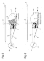
- the device 1 is intended to be mounted on a helicopter 2 comprising a base frame 3 supporting at least a pilot's cab 4 and at least a rotor 5, 6.
- the helicopter 2 has two rotors 5, 6, one primary rotor 5, revolving around a substantially vertical primary axis A, and a secondary stabilization rotor 6, revolving around a substantially horizontal secondary axis B fitted to the tail of the helicopter 2 (see figures 5 and 6 ).
- the device 1 comprises:
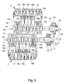
- the two engines 7, 9 operate independently from a mechanical viewpoint but are integrated in a single engine body 13, 14, 15, 16, 17, 18, 19.
- the engines 7, 9 comprise a central guard 13, a first side guard 14 and a second side guard 15, the first engine shaft 8 being housed between the central guard 13 and the first side guard 14 and the second engine shaft 10 being housed between the central guard 13 and the second side guard 15.
- the first engine 7 also comprises a first unit 16 of first cylinders 16a wherein are housed sliding a plurality of first pistons 16b which, by means of corresponding first connecting rods 16c, are suitable for operating the first engine shaft 8 in rotation.
- the first unit 16 consists, e.g., of a single block which is associated with the first side guard 14 in assembly phase, e.g., by means of screws, bolts or the like; alternative embodiments cannot however be ruled out wherein the first side guard 14 and the first unit 16 are made in a single body piece.
- the first engine 7 also comprises a first cylinder head 17, for closing the first cylinders 16a.
- the first cylinder head 17, e.g., houses the suction and exhaust valves of each first cylinder 16a and is associated with the first unit 16 in assembly phase, e.g., by means of screws, bolts or the like.
- the second engine 9 comprises a second unit 18 of second cylinders 18a wherein are housed sliding a plurality of second pistons 18b which, by means of corresponding second connecting rods 18c, are suitable for operating the second engine shaft 10 in rotation.
- the second unit 18 consists, e.g., of a single block which is associated with the second side guard 15 in assembly phase, e.g., by means of screws, bolts or the like; alternative embodiments cannot however be ruled out wherein the second side guard 15 and the second unit 18 are made in a single body piece.
- the second engine 9, furthermore, comprises a second cylinder head 19, for closing the second cylinders 18a.
- the first cylinders 16a and the second cylinders 18a are arranged horizontally, i.e., defining a sliding direction of the pistons 16b, 18b which is horizontal.
- the first cylinders 16a and the second cylinders 18a are arranged in opposite lines, i.e., the cylinders 16a, 18a of each engine 7, 9 are arranged in line, with the sliding directions of the pistons 16b, 18b parallel to one another and each line is positioned at 180° with respect to the other.
- first engine shaft 8, the second engine shaft 10 and the drive shaft 12 are substantially parallel to one another and, in particular, are substantially horizontal.
- the transmission unit 11 comprises:
- the flexible transmission elements 24, 29 consist of respective drive belts, made e.g. of a material such as textile fibres or rubber covered nylon threads, steel wires or rubber covered carbon fibres, the very nature of which reduces the vibrations and makes the transmission of motion to the rotors 5, 6 more uniform.
- the first engine shaft 8 and the second engine shaft 10 are of the same length and are axially staggered by a preset distance D1.
- the engine shafts 8, 10 are substantially identical the one to the other, so as to reduce their production and industrialization costs, and the first cylinders 16a are staggered with respect to the second cylinders 18a by a distance equal to the preset distance D1.
- a device 1 can be obtained with considerably reduced overall dimensions, with a very small centre distance D2 and an extension in axial direction which is as compact as possible.
- the driven pulleys 22, 27 are fitted on the drive shaft 12 one in the proximity of the other.
- the drive shaft 12 which as has been said is substantially horizontal, terminates in an extremity wherein the motion is deviated upwards, i.e., towards the primary rotor 5, e.g., by means of a conventional system of bevel gear wheels and a reduction unit, not shown in the illustrations.
- the drive shaft 12 has an extension extending along the entire tail of the helicopter 2 to transmit the motion to the secondary rotor 6, e.g., by means of a second system of bevel gear wheels, not shown in the illustrations.
- each engine 7, 9 is sized with a substantial power rating of 120 HP and can be used, at the same time as the other, to rotate both rotors 5, 6.
- Each engine 7, 9 has its own lubrication, supply and electronic control system, as well as its own supply and injection redundancy according to air-force patterns.
- the running of the two engines 7, 9 is supervised by the FAD EC system, which is designed to control the supply and the electronic control system of the individual engines 7, 9 (injection, ignition), including redundancy and diagnostics, as well as having the function of managing optimization in conditions of coordinated operation (synchronization) and emergency of the two engines 7, 9.
- the FAD EC system which is designed to control the supply and the electronic control system of the individual engines 7, 9 (injection, ignition), including redundancy and diagnostics, as well as having the function of managing optimization in conditions of coordinated operation (synchronization) and emergency of the two engines 7, 9.
- helicopter 2 equipped with the device 1 as previously described can be an aircraft of the following type:
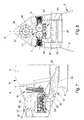
- the device 1 also comprises an air-cooling system 31 suitable for cooling the engines 7, 9 and having:
- the front air vent 32 is located under the pilot's cab 4 while the outlet mouth 38 is located behind the pilot's cab 4 substantially around the drive shaft 12.
- the flow duct 33, 34, 35, 36 comprises:
- the inlet manifold 33 substantially extends horizontally from the front air vent 32 as far as underneath the engines 7,9.
- the cooling branches 34, 35 deviate the air flow upwards so as to cool the cylinder units 16, 18 and the cylinder heads 17, 19, which for this purpose are equipped with fins.
- the cooling branches 34, 35 again deviate the air flow, returning it to horizontal position, and then connect to the outlet manifold 36, which extends substantially horizontally from the cooling branches 34, 35 to the outlet mouth 38.
- the suction impeller 37 is arranged in correspondence of the outlet manifold 36, substantially in the proximity of the outlet mouth 38.
- the suction impeller 37 is associated with the drive shaft 12 with interposition of clutch means 39, of the type of an electro-clutch.
- the clutch means 39 can be controlled by the pilot or by the FADEC system, making it possible to connect and disconnect the suction impeller 37 according to the different flight conditions.
- the air-cooling system 31 also comprises at least a radiator unit 40 arranged along the flow duct 33, 34, 35, 36 and designed to allow heat exchange with a liquid cooling system.
- the radiator unit 40 consists, e.g., of an air/liquid heat exchanger, externally brushed by the air that crosses the flow duct 33, 34, 35, 36 and internally crossed by a cooling liquid, of the oil type or the like.
- the cooling liquid circulates inside the liquid cooling system which is not shown in detail in the illustrations and is used to cool the inner parts of the engines 7, 9 or other components of the helicopter 2 which require cooling, such as drive gears, reduction units and the like.
- the radiator unit 40 is located in correspondence of the inlet manifold 33.
- the inlet manifold 33 has a section widening in correspondence of the radiator unit 40, and this permits a reduction in the speed of flow, flow rate being equal, and a consequent increase in heat exchange efficiency.
- the flow duct 33, 34, 35, 36 is shaped and sized so as to ensure a global heat exchange provided by the sum of the heat exchange with the radiator unit 40 and of the heat exchange with the engines 7, 9.
- the propulsion device according to the present invention allows to obtain a twin-engine helicopter with extensive operating options and which, nevertheless, has an enormously reduced cost, both in terms of lower production costs (e.g., around 300,000 Euro) and lower running costs (e.g., around 200 - 250 Euro per hour of use).
- lower production costs e.g., around 300,000 Euro
- lower running costs e.g., around 200 - 250 Euro per hour of use
Landscapes
- Engineering & Computer Science (AREA)
- Mechanical Engineering (AREA)
- Aviation & Aerospace Engineering (AREA)
- Transmission Devices (AREA)
- Cylinder Crankcases Of Internal Combustion Engines (AREA)
Applications Claiming Priority (1)
| Application Number | Priority Date | Filing Date | Title |
|---|---|---|---|
| ITMO20140145 | 2014-05-23 |
Publications (2)
| Publication Number | Publication Date |
|---|---|
| EP2947014A1 true EP2947014A1 (fr) | 2015-11-25 |
| EP2947014B1 EP2947014B1 (fr) | 2017-03-01 |
Family
ID=50979647
Family Applications (1)
| Application Number | Title | Priority Date | Filing Date |
|---|---|---|---|
| EP14173559.7A Active EP2947014B1 (fr) | 2014-05-23 | 2014-06-23 | Dispositif de propulsion pour hélicoptères |
Country Status (1)
| Country | Link |
|---|---|
| EP (1) | EP2947014B1 (fr) |
Cited By (3)
| Publication number | Priority date | Publication date | Assignee | Title |
|---|---|---|---|---|
| ITUA20162036A1 (it) * | 2016-03-25 | 2017-09-25 | Robby Moto Eng S R L | Velivolo a doppia elica |
| CN108238259A (zh) * | 2018-02-08 | 2018-07-03 | 天津曙光天成科技有限公司 | 一种动力装置及无人直升机 |
| EP3967606A1 (fr) * | 2020-09-09 | 2022-03-16 | Robby Moto Engineering S.r.l. | Giravion |
Citations (13)
| Publication number | Priority date | Publication date | Assignee | Title |
|---|---|---|---|---|
| GB191224096A (en) * | 1911-12-02 | 1913-08-07 | Jacob Lohner & Co | Improvements in and relating to Driving Mechanism for Aeroplanes. |
| US1934399A (en) * | 1930-07-08 | 1933-11-07 | Wright Aerenautical Corp | Method of and apparatus for cooling internal combustion engines |
| US2640469A (en) * | 1945-05-09 | 1953-06-02 | United Aircraft Corp | Combined air fan and clutch for engine cooling |
| DE904486C (de) * | 1951-09-29 | 1954-02-18 | Willy Messerschmitt Dr Ing | Triebwerk mit zwei auf eine Welle arbeitenden Otto- oder Dieselmotoren |
| US2947497A (en) * | 1957-05-06 | 1960-08-02 | Omega Aircraft Corp | Dual engine drive means for helicopters |
| FR1279737A (fr) * | 1961-01-24 | 1961-12-22 | Perfectionnements apportés aux mécanismes propulseurs pour avions, plus spécialement pour des petits avions ou des avions de sport | |
| DE1174170B (de) * | 1961-07-04 | 1964-07-16 | Eberhard Krueger | Hubschrauber |
| US3474876A (en) * | 1966-02-09 | 1969-10-28 | Renault | Power and transmission units for automotive vehicles or the like |
| DE3522988A1 (de) * | 1984-12-13 | 1986-06-26 | Claudius Dr. 5000 Köln Kaniut jun. | Split - motor fuer kraftfahrzeuge mit geteilter kurbelwelle und motor - querwelle fuer hilfsgeraete - antriebe |
| EP0283578A2 (fr) * | 1987-03-26 | 1988-09-28 | Dr.Ing.h.c. F. Porsche Aktiengesellschaft | Aéronef, en particulier hélicoptère |
| KR20100109717A (ko) * | 2009-04-01 | 2010-10-11 | 원신 스카이텍 주식회사 | 무인헬기의 엔진 냉각 시스템 |
| DE102010025454A1 (de) * | 2009-07-28 | 2011-02-03 | Luk Lamellen Und Kupplungsbau Beteiligungs Kg | Fahrzeugantrieb |
| EP2615033A2 (fr) * | 2012-01-12 | 2013-07-17 | Hamilton Sundstrand Corporation | Système d'embrayage pour aéronef à voilure tournante avec système de butée secondaire |
-
2014
- 2014-06-23 EP EP14173559.7A patent/EP2947014B1/fr active Active
Patent Citations (13)
| Publication number | Priority date | Publication date | Assignee | Title |
|---|---|---|---|---|
| GB191224096A (en) * | 1911-12-02 | 1913-08-07 | Jacob Lohner & Co | Improvements in and relating to Driving Mechanism for Aeroplanes. |
| US1934399A (en) * | 1930-07-08 | 1933-11-07 | Wright Aerenautical Corp | Method of and apparatus for cooling internal combustion engines |
| US2640469A (en) * | 1945-05-09 | 1953-06-02 | United Aircraft Corp | Combined air fan and clutch for engine cooling |
| DE904486C (de) * | 1951-09-29 | 1954-02-18 | Willy Messerschmitt Dr Ing | Triebwerk mit zwei auf eine Welle arbeitenden Otto- oder Dieselmotoren |
| US2947497A (en) * | 1957-05-06 | 1960-08-02 | Omega Aircraft Corp | Dual engine drive means for helicopters |
| FR1279737A (fr) * | 1961-01-24 | 1961-12-22 | Perfectionnements apportés aux mécanismes propulseurs pour avions, plus spécialement pour des petits avions ou des avions de sport | |
| DE1174170B (de) * | 1961-07-04 | 1964-07-16 | Eberhard Krueger | Hubschrauber |
| US3474876A (en) * | 1966-02-09 | 1969-10-28 | Renault | Power and transmission units for automotive vehicles or the like |
| DE3522988A1 (de) * | 1984-12-13 | 1986-06-26 | Claudius Dr. 5000 Köln Kaniut jun. | Split - motor fuer kraftfahrzeuge mit geteilter kurbelwelle und motor - querwelle fuer hilfsgeraete - antriebe |
| EP0283578A2 (fr) * | 1987-03-26 | 1988-09-28 | Dr.Ing.h.c. F. Porsche Aktiengesellschaft | Aéronef, en particulier hélicoptère |
| KR20100109717A (ko) * | 2009-04-01 | 2010-10-11 | 원신 스카이텍 주식회사 | 무인헬기의 엔진 냉각 시스템 |
| DE102010025454A1 (de) * | 2009-07-28 | 2011-02-03 | Luk Lamellen Und Kupplungsbau Beteiligungs Kg | Fahrzeugantrieb |
| EP2615033A2 (fr) * | 2012-01-12 | 2013-07-17 | Hamilton Sundstrand Corporation | Système d'embrayage pour aéronef à voilure tournante avec système de butée secondaire |
Cited By (4)
| Publication number | Priority date | Publication date | Assignee | Title |
|---|---|---|---|---|
| ITUA20162036A1 (it) * | 2016-03-25 | 2017-09-25 | Robby Moto Eng S R L | Velivolo a doppia elica |
| EP3222518A1 (fr) * | 2016-03-25 | 2017-09-27 | Robby Moto Engineering S.r.l. | Aéronef double hélice |
| CN108238259A (zh) * | 2018-02-08 | 2018-07-03 | 天津曙光天成科技有限公司 | 一种动力装置及无人直升机 |
| EP3967606A1 (fr) * | 2020-09-09 | 2022-03-16 | Robby Moto Engineering S.r.l. | Giravion |
Also Published As
| Publication number | Publication date |
|---|---|
| EP2947014B1 (fr) | 2017-03-01 |
Similar Documents
| Publication | Publication Date | Title |
|---|---|---|
| CA2555056C (fr) | Turbine a gaz a corps multiples | |
| US10294822B2 (en) | Turbine engine nacelle fitted with a heat exchanger | |
| US9637240B2 (en) | Aircraft powerplant | |
| RU2458826C2 (ru) | Усовершенствование винтокрылого летательного аппарата, оснащенного газотурбинными двигателями | |
| CA2758545C (fr) | Aeronef et systeme de propulsion | |
| US8562284B2 (en) | Propulsive fan system | |
| CN112664320A (zh) | 燃气涡轮发动机增压器构造和操作方法 | |
| US8297038B2 (en) | Gas turbine aircraft engines and operation thereof | |
| NZ569455A (en) | Propulsion device incorporating radiator cooling passage | |
| EP2947013B1 (fr) | Hélicoptère | |
| EP2947014B1 (fr) | Dispositif de propulsion pour hélicoptères | |
| US9957040B2 (en) | Propeller gearbox oil cooler for a rotary wing aircract | |
| ITTO20100703A1 (it) | Gruppo di propulsione e trasmissione del moto, particolarmente per un velivolo ad ala rotante | |
| CA2826127C (fr) | Systemes et methodes d'entrainement d'un ventilateur de refroidissement d'huile d'une turbine a gaz | |
| EP3527490A1 (fr) | Aéronef équipé d'un ensemble moteur monté sur la baie du train d'atterrissage | |
| EP3222518B1 (fr) | Aéronef double hélice | |
| RU2536421C2 (ru) | Силовая установка с изменяемым вектором тяги | |
| EP3527497B1 (fr) | Aéronef comportant un baie de train d'atterrissage entre les sorties des conduits de refroidissement | |
| CN206092173U (zh) | 一种直列无人机发动机 | |
| EP3527496B1 (fr) | Aéronef équipé d'une baie de train d'atterrissage entre des échangeurs de chaleur d'un ensemble moteur | |
| RU2698497C1 (ru) | Летательный аппарат вертикального взлета и посадки | |
| RU2701076C1 (ru) | Вертолет | |
| US11148822B2 (en) | Drive system arrangement for rotorcraft | |
| US20110182723A1 (en) | Turbomachine aircraft propeller | |
| Norton | The design and development of the twin Centaurus power plant for the Bristol “Brabazon” |
Legal Events
| Date | Code | Title | Description |
|---|---|---|---|
| PUAI | Public reference made under article 153(3) epc to a published international application that has entered the european phase |
Free format text: ORIGINAL CODE: 0009012 |
|
| AK | Designated contracting states |
Kind code of ref document: A1 Designated state(s): AL AT BE BG CH CY CZ DE DK EE ES FI FR GB GR HR HU IE IS IT LI LT LU LV MC MK MT NL NO PL PT RO RS SE SI SK SM TR |
|
| AX | Request for extension of the european patent |
Extension state: BA ME |
|
| 17P | Request for examination filed |
Effective date: 20160525 |
|
| RBV | Designated contracting states (corrected) |
Designated state(s): AL AT BE BG CH CY CZ DE DK EE ES FI FR GB GR HR HU IE IS IT LI LT LU LV MC MK MT NL NO PL PT RO RS SE SI SK SM TR |
|
| GRAP | Despatch of communication of intention to grant a patent |
Free format text: ORIGINAL CODE: EPIDOSNIGR1 |
|
| STAA | Information on the status of an ep patent application or granted ep patent |
Free format text: STATUS: GRANT OF PATENT IS INTENDED |
|
| RIC1 | Information provided on ipc code assigned before grant |
Ipc: B64C 27/12 20060101ALI20161027BHEP Ipc: B64D 35/08 20060101AFI20161027BHEP |
|
| INTG | Intention to grant announced |
Effective date: 20161117 |
|
| GRAS | Grant fee paid |
Free format text: ORIGINAL CODE: EPIDOSNIGR3 |
|
| GRAA | (expected) grant |
Free format text: ORIGINAL CODE: 0009210 |
|
| STAA | Information on the status of an ep patent application or granted ep patent |
Free format text: STATUS: THE PATENT HAS BEEN GRANTED |
|
| AK | Designated contracting states |
Kind code of ref document: B1 Designated state(s): AL AT BE BG CH CY CZ DE DK EE ES FI FR GB GR HR HU IE IS IT LI LT LU LV MC MK MT NL NO PL PT RO RS SE SI SK SM TR |
|
| REG | Reference to a national code |
Ref country code: GB Ref legal event code: FG4D |
|
| REG | Reference to a national code |
Ref country code: CH Ref legal event code: EP Ref country code: AT Ref legal event code: REF Ref document number: 870958 Country of ref document: AT Kind code of ref document: T Effective date: 20170315 |
|
| REG | Reference to a national code |
Ref country code: IE Ref legal event code: FG4D |
|
| REG | Reference to a national code |
Ref country code: DE Ref legal event code: R096 Ref document number: 602014007030 Country of ref document: DE |
|
| REG | Reference to a national code |
Ref country code: NL Ref legal event code: MP Effective date: 20170301 |
|
| REG | Reference to a national code |
Ref country code: LT Ref legal event code: MG4D |
|
| REG | Reference to a national code |
Ref country code: AT Ref legal event code: MK05 Ref document number: 870958 Country of ref document: AT Kind code of ref document: T Effective date: 20170301 |
|
| PG25 | Lapsed in a contracting state [announced via postgrant information from national office to epo] |
Ref country code: FI Free format text: LAPSE BECAUSE OF FAILURE TO SUBMIT A TRANSLATION OF THE DESCRIPTION OR TO PAY THE FEE WITHIN THE PRESCRIBED TIME-LIMIT Effective date: 20170301 Ref country code: NO Free format text: LAPSE BECAUSE OF FAILURE TO SUBMIT A TRANSLATION OF THE DESCRIPTION OR TO PAY THE FEE WITHIN THE PRESCRIBED TIME-LIMIT Effective date: 20170601 Ref country code: HR Free format text: LAPSE BECAUSE OF FAILURE TO SUBMIT A TRANSLATION OF THE DESCRIPTION OR TO PAY THE FEE WITHIN THE PRESCRIBED TIME-LIMIT Effective date: 20170301 Ref country code: LT Free format text: LAPSE BECAUSE OF FAILURE TO SUBMIT A TRANSLATION OF THE DESCRIPTION OR TO PAY THE FEE WITHIN THE PRESCRIBED TIME-LIMIT Effective date: 20170301 Ref country code: GR Free format text: LAPSE BECAUSE OF FAILURE TO SUBMIT A TRANSLATION OF THE DESCRIPTION OR TO PAY THE FEE WITHIN THE PRESCRIBED TIME-LIMIT Effective date: 20170602 |
|
| PG25 | Lapsed in a contracting state [announced via postgrant information from national office to epo] |
Ref country code: ES Free format text: LAPSE BECAUSE OF FAILURE TO SUBMIT A TRANSLATION OF THE DESCRIPTION OR TO PAY THE FEE WITHIN THE PRESCRIBED TIME-LIMIT Effective date: 20170301 Ref country code: LV Free format text: LAPSE BECAUSE OF FAILURE TO SUBMIT A TRANSLATION OF THE DESCRIPTION OR TO PAY THE FEE WITHIN THE PRESCRIBED TIME-LIMIT Effective date: 20170301 Ref country code: AT Free format text: LAPSE BECAUSE OF FAILURE TO SUBMIT A TRANSLATION OF THE DESCRIPTION OR TO PAY THE FEE WITHIN THE PRESCRIBED TIME-LIMIT Effective date: 20170301 Ref country code: BG Free format text: LAPSE BECAUSE OF FAILURE TO SUBMIT A TRANSLATION OF THE DESCRIPTION OR TO PAY THE FEE WITHIN THE PRESCRIBED TIME-LIMIT Effective date: 20170601 Ref country code: SE Free format text: LAPSE BECAUSE OF FAILURE TO SUBMIT A TRANSLATION OF THE DESCRIPTION OR TO PAY THE FEE WITHIN THE PRESCRIBED TIME-LIMIT Effective date: 20170301 Ref country code: RS Free format text: LAPSE BECAUSE OF FAILURE TO SUBMIT A TRANSLATION OF THE DESCRIPTION OR TO PAY THE FEE WITHIN THE PRESCRIBED TIME-LIMIT Effective date: 20170301 |
|
| PG25 | Lapsed in a contracting state [announced via postgrant information from national office to epo] |
Ref country code: NL Free format text: LAPSE BECAUSE OF FAILURE TO SUBMIT A TRANSLATION OF THE DESCRIPTION OR TO PAY THE FEE WITHIN THE PRESCRIBED TIME-LIMIT Effective date: 20170301 |
|
| PG25 | Lapsed in a contracting state [announced via postgrant information from national office to epo] |
Ref country code: CZ Free format text: LAPSE BECAUSE OF FAILURE TO SUBMIT A TRANSLATION OF THE DESCRIPTION OR TO PAY THE FEE WITHIN THE PRESCRIBED TIME-LIMIT Effective date: 20170301 Ref country code: EE Free format text: LAPSE BECAUSE OF FAILURE TO SUBMIT A TRANSLATION OF THE DESCRIPTION OR TO PAY THE FEE WITHIN THE PRESCRIBED TIME-LIMIT Effective date: 20170301 Ref country code: RO Free format text: LAPSE BECAUSE OF FAILURE TO SUBMIT A TRANSLATION OF THE DESCRIPTION OR TO PAY THE FEE WITHIN THE PRESCRIBED TIME-LIMIT Effective date: 20170301 Ref country code: SK Free format text: LAPSE BECAUSE OF FAILURE TO SUBMIT A TRANSLATION OF THE DESCRIPTION OR TO PAY THE FEE WITHIN THE PRESCRIBED TIME-LIMIT Effective date: 20170301 |
|
| PG25 | Lapsed in a contracting state [announced via postgrant information from national office to epo] |
Ref country code: PL Free format text: LAPSE BECAUSE OF FAILURE TO SUBMIT A TRANSLATION OF THE DESCRIPTION OR TO PAY THE FEE WITHIN THE PRESCRIBED TIME-LIMIT Effective date: 20170301 Ref country code: SM Free format text: LAPSE BECAUSE OF FAILURE TO SUBMIT A TRANSLATION OF THE DESCRIPTION OR TO PAY THE FEE WITHIN THE PRESCRIBED TIME-LIMIT Effective date: 20170301 Ref country code: IS Free format text: LAPSE BECAUSE OF FAILURE TO SUBMIT A TRANSLATION OF THE DESCRIPTION OR TO PAY THE FEE WITHIN THE PRESCRIBED TIME-LIMIT Effective date: 20170701 Ref country code: PT Free format text: LAPSE BECAUSE OF FAILURE TO SUBMIT A TRANSLATION OF THE DESCRIPTION OR TO PAY THE FEE WITHIN THE PRESCRIBED TIME-LIMIT Effective date: 20170703 |
|
| REG | Reference to a national code |
Ref country code: DE Ref legal event code: R097 Ref document number: 602014007030 Country of ref document: DE |
|
| REG | Reference to a national code |
Ref country code: DE Ref legal event code: R119 Ref document number: 602014007030 Country of ref document: DE |
|
| PLBE | No opposition filed within time limit |
Free format text: ORIGINAL CODE: 0009261 |
|
| STAA | Information on the status of an ep patent application or granted ep patent |
Free format text: STATUS: NO OPPOSITION FILED WITHIN TIME LIMIT |
|
| PG25 | Lapsed in a contracting state [announced via postgrant information from national office to epo] |
Ref country code: MC Free format text: LAPSE BECAUSE OF FAILURE TO SUBMIT A TRANSLATION OF THE DESCRIPTION OR TO PAY THE FEE WITHIN THE PRESCRIBED TIME-LIMIT Effective date: 20170301 Ref country code: DK Free format text: LAPSE BECAUSE OF FAILURE TO SUBMIT A TRANSLATION OF THE DESCRIPTION OR TO PAY THE FEE WITHIN THE PRESCRIBED TIME-LIMIT Effective date: 20170301 |
|
| REG | Reference to a national code |
Ref country code: CH Ref legal event code: PL |
|
| 26N | No opposition filed |
Effective date: 20171204 |
|
| PG25 | Lapsed in a contracting state [announced via postgrant information from national office to epo] |
Ref country code: SI Free format text: LAPSE BECAUSE OF FAILURE TO SUBMIT A TRANSLATION OF THE DESCRIPTION OR TO PAY THE FEE WITHIN THE PRESCRIBED TIME-LIMIT Effective date: 20170301 |
|
| REG | Reference to a national code |
Ref country code: IE Ref legal event code: MM4A |
|
| REG | Reference to a national code |
Ref country code: FR Ref legal event code: ST Effective date: 20180228 |
|
| PG25 | Lapsed in a contracting state [announced via postgrant information from national office to epo] |
Ref country code: CH Free format text: LAPSE BECAUSE OF NON-PAYMENT OF DUE FEES Effective date: 20170630 Ref country code: LI Free format text: LAPSE BECAUSE OF NON-PAYMENT OF DUE FEES Effective date: 20170630 Ref country code: LU Free format text: LAPSE BECAUSE OF NON-PAYMENT OF DUE FEES Effective date: 20170623 Ref country code: IE Free format text: LAPSE BECAUSE OF NON-PAYMENT OF DUE FEES Effective date: 20170623 Ref country code: DE Free format text: LAPSE BECAUSE OF NON-PAYMENT OF DUE FEES Effective date: 20180103 |
|
| PG25 | Lapsed in a contracting state [announced via postgrant information from national office to epo] |
Ref country code: FR Free format text: LAPSE BECAUSE OF NON-PAYMENT OF DUE FEES Effective date: 20170630 |
|
| REG | Reference to a national code |
Ref country code: BE Ref legal event code: MM Effective date: 20170630 |
|
| PG25 | Lapsed in a contracting state [announced via postgrant information from national office to epo] |
Ref country code: BE Free format text: LAPSE BECAUSE OF NON-PAYMENT OF DUE FEES Effective date: 20170630 |
|
| PG25 | Lapsed in a contracting state [announced via postgrant information from national office to epo] |
Ref country code: MT Free format text: LAPSE BECAUSE OF NON-PAYMENT OF DUE FEES Effective date: 20170623 |
|
| GBPC | Gb: european patent ceased through non-payment of renewal fee |
Effective date: 20180623 |
|
| PG25 | Lapsed in a contracting state [announced via postgrant information from national office to epo] |
Ref country code: GB Free format text: LAPSE BECAUSE OF NON-PAYMENT OF DUE FEES Effective date: 20180623 |
|
| PG25 | Lapsed in a contracting state [announced via postgrant information from national office to epo] |
Ref country code: HU Free format text: LAPSE BECAUSE OF FAILURE TO SUBMIT A TRANSLATION OF THE DESCRIPTION OR TO PAY THE FEE WITHIN THE PRESCRIBED TIME-LIMIT; INVALID AB INITIO Effective date: 20140623 |
|
| PG25 | Lapsed in a contracting state [announced via postgrant information from national office to epo] |
Ref country code: CY Free format text: LAPSE BECAUSE OF FAILURE TO SUBMIT A TRANSLATION OF THE DESCRIPTION OR TO PAY THE FEE WITHIN THE PRESCRIBED TIME-LIMIT Effective date: 20170301 |
|
| PG25 | Lapsed in a contracting state [announced via postgrant information from national office to epo] |
Ref country code: MK Free format text: LAPSE BECAUSE OF FAILURE TO SUBMIT A TRANSLATION OF THE DESCRIPTION OR TO PAY THE FEE WITHIN THE PRESCRIBED TIME-LIMIT Effective date: 20170301 |
|
| PG25 | Lapsed in a contracting state [announced via postgrant information from national office to epo] |
Ref country code: TR Free format text: LAPSE BECAUSE OF FAILURE TO SUBMIT A TRANSLATION OF THE DESCRIPTION OR TO PAY THE FEE WITHIN THE PRESCRIBED TIME-LIMIT Effective date: 20170301 |
|
| PG25 | Lapsed in a contracting state [announced via postgrant information from national office to epo] |
Ref country code: AL Free format text: LAPSE BECAUSE OF FAILURE TO SUBMIT A TRANSLATION OF THE DESCRIPTION OR TO PAY THE FEE WITHIN THE PRESCRIBED TIME-LIMIT Effective date: 20170301 |
|
| P01 | Opt-out of the competence of the unified patent court (upc) registered |
Effective date: 20230527 |
|
| PGFP | Annual fee paid to national office [announced via postgrant information from national office to epo] |
Ref country code: IT Payment date: 20250618 Year of fee payment: 12 |