EP2947221B1 - Fenêtre de toit et procédé de montage d'une fenêtre de toit - Google Patents
Fenêtre de toit et procédé de montage d'une fenêtre de toit Download PDFInfo
- Publication number
- EP2947221B1 EP2947221B1 EP15168661.5A EP15168661A EP2947221B1 EP 2947221 B1 EP2947221 B1 EP 2947221B1 EP 15168661 A EP15168661 A EP 15168661A EP 2947221 B1 EP2947221 B1 EP 2947221B1
- Authority
- EP
- European Patent Office
- Prior art keywords
- push rod
- roof window
- region
- operating
- frame
- Prior art date
- Legal status (The legal status is an assumption and is not a legal conclusion. Google has not performed a legal analysis and makes no representation as to the accuracy of the status listed.)
- Active
Links
Images




Classifications
-
- E—FIXED CONSTRUCTIONS
- E04—BUILDING
- E04D—ROOF COVERINGS; SKY-LIGHTS; GUTTERS; ROOF-WORKING TOOLS
- E04D13/00—Special arrangements or devices in connection with roof coverings; Protection against birds; Roof drainage ; Sky-lights
- E04D13/03—Sky-lights; Domes; Ventilating sky-lights
-
- E—FIXED CONSTRUCTIONS
- E04—BUILDING
- E04D—ROOF COVERINGS; SKY-LIGHTS; GUTTERS; ROOF-WORKING TOOLS
- E04D13/00—Special arrangements or devices in connection with roof coverings; Protection against birds; Roof drainage ; Sky-lights
- E04D13/03—Sky-lights; Domes; Ventilating sky-lights
- E04D13/0325—Sky-lights; Domes; Ventilating sky-lights provided with ventilating means
-
- E—FIXED CONSTRUCTIONS
- E05—LOCKS; KEYS; WINDOW OR DOOR FITTINGS; SAFES
- E05B—LOCKS; ACCESSORIES THEREFOR; HANDCUFFS
- E05B9/00—Lock casings or latch-mechanism casings ; Fastening locks or fasteners or parts thereof to the wing
- E05B9/08—Fastening locks or fasteners or parts thereof, e.g. the casings of latch-bolt locks or cylinder locks to the wing
-
- E—FIXED CONSTRUCTIONS
- E05—LOCKS; KEYS; WINDOW OR DOOR FITTINGS; SAFES
- E05B—LOCKS; ACCESSORIES THEREFOR; HANDCUFFS
- E05B15/00—Other details of locks; Parts for engagement by bolts of fastening devices
- E05B15/0006—Devices for aligning wing and frame; Anti-rattling devices
Definitions
- the invention relates to a roof window, in particular roof windows, with a frame, a sash and a locking device having at least one locking latch, the sash relative to the frame sets in a closed position in a closed position in a closed position and releases in a release position for opening the roof window.
- the invention further relates to a method for mounting a roof window.
- WO 2012/034558 A discloses the features of the preamble of the first claim.
- the roof window or roof window according to the invention has as essential components of the frame and the sash.
- the casement usually has a glazing, which is present for example as multiple, in particular double glazing or triple glazing. Of course, a single glazing can be realized.
- the glazing is bordered, for example, by bars of the casement, wherein in particular two vertical bars and two horizontal bars are provided.
- the frame also preferably has two vertical bars and two horizontal bars. In each case, two of the spars are connected to each other, in particular, each of the vertical beams is connected to each of the horizontal beams.
- the frame is provided for example for stationary attachment to a roof or for attachment in a recess of the roof.
- the casement is movably mounted on the frame and pivotable relative to this at least one axis.
- the pivoting can be carried out in particular as flaps, swings or swinging.
- Flaps is the axis in an upper region of the roof window, in particular in an upper third of the roof window - in relation to the height - or in the region of the upper edge.
- the axis lies in a central region of the roof window, in particular in a second third of the height of the roof window.
- the pivoting serves, for example, to bring the casement from the closed position to a second open position, in particular cleaning position, or vice versa. In the cleaning position, an outer glass surface can be cleaned easily and easily.
- the pivoting takes place about several axes, which are usually parallel to each other. For example, when swinging at the same time pivoting about the axis used for the flap and the axis used for pivoting before.
- the swinging serves, for example, to bring the casement from the closed position into a third open position, in particular a ventilation position.
- the roof window also has the locking device.
- the locking device serves to lock the roof window, so therefore set the sash with respect to the frame in its closed position.
- the roof window is locked by means of the locking device, while the sash is in its closed position, so below is the sash relative to the frame in the closed position fixed until the roof window is unlocked again.
- the locking device is actuated for locking the roof window, as long as the casement outside the closed position, for example in the open position, it may be provided that no setting of the casement takes place.
- the locking device has the locking latch, which can be present in at least two positions, namely the locking position and the release position.
- the locking position the roof window is locked, so the sash set relative to the frame in its closed position. If, on the other hand, the locking bolt is displaced into the release position, then the casement is released so that subsequently the roof window can be opened.
- a plurality of locking bolts in particular at least two locking bolts, may be provided.
- the one or more locking bars are preferably arranged on the casement or movably mounted on this.
- a closing block which is fastened in particular to the window frame.
- a reverse arrangement can be realized in which the locking latch on the window frame and the locking block is present on the sash.
- the actuating element is held captive in a keyhole-shaped retaining recess of the locking device in a keyhole-shaped holding recess in the retaining recess in a lying outside the actuation range, wherein a push rod is attached to the actuation region, which has a push rod fastening element in a push rod mounting angle position in a push rod receptacle of the actuating element can be introduced and is held in a push rod operating angle position in the push rod receptacle.
- Such an embodiment of the roof window or the locking device is used in particular to realize a tool-free installation of the actuating element in the retaining recess and the push rod on the actuating element and thus significantly reduce the effort in the assembly of the roof window.
- the locking latch is actuated by means of the actuating element and the push rod.
- the locking bolt via the actuating element and the push rod with a handle, in particular a pivoting handle, the roof window operatively connected.
- the handle engages the push rod, which engages with its end facing away from the handle on the actuating element.
- the displacement of the actuating element within the operating range is thus achieved via the push rod by a movement of the handle, in particular a pivoting of the handle.
- the actuating element is now operatively connected to the locking bolt, for example via a lever arrangement.
- the lever arrangement can be designed such that it is present in at least one position of the actuating element in an over-center arrangement. This is the case, in particular, in the case of an embodiment of the roof window in which the closure latch is intended to be operable on the one hand by means of the handle and on the other hand by means of a drive device, in particular an electric drive device.
- the actuating element is inserted in the mounting recess of the roof window or the locking device.
- the actuating element is arranged with respect to the retaining recess in the Betjanistselementmontagegna in which it can be introduced into the retaining recess. Subsequently, it is displaced from the Betreliistselementmontagegna in one of this different position, which is preferably within the operating range.
- the operating region of the actuating element is the region in which the actuating element can be arranged during normal operation of the roof window.
- the actuator is in any position of the handle of the roof window in the operating area.
- the actuating element and the holding recess are designed such that the actuating element can be used exclusively in the actuating element mounting position in the holding recess or can be removed therefrom. This means that during normal operation of the skylight during which the actuator is always within the operating range is located, the actuator can not get out of the holding recess.
- the actuating element is held by the push rod in the actuating region, in particular as long as the push rod is fastened or hinged on the one hand to the actuating element and on the other hand to the handle of the roof window.
- the actuator is tool-free fastened in the holding recess.
- the push rod can be fastened or articulated without tools, in particular on the actuating element.
- the push rod on the push rod attachment member and the actuator on the push rod receptacle are now designed such that the push rod fastening element can be introduced into the push rod receptacle only in the push rod mounting angle position.
- the push rod is in the push rod operating angle position, which is different than the push rod mounting angle position.
- the push rod operating angle position In the push rod operating angle position, the push rod or the push rod fastener thus securely held in the push rod receptacle.
- the push rod operating angle position may be within a push rod operating angular position range in which the push rod is held in the push rod receptacle.
- the push rod mounting angle position is now outside of this push rod operating angular position range.
- the push rod receptacle is designed, for example, keyhole-shaped at least in some areas, that is to say it has a larger-scale area and a smaller-scale area.
- the dimensionally smaller area is preferably open to the edge, so that the push rod fastening element can be brought into the dimensionally smaller area and through it into the larger-dimensional area.
- the push rod is displaced from the push rod mounting angle position in the push rod operating angle position.
- the push rod attachment member has a cross section which is selected such that it can be displaced through the smaller dimension in the push rod mounting angle position, while in the push rod operating angle position it no longer fits into or through it, ie not from the larger dimension range in the dimension smaller area can get.
- the locking bolt is operatively connected to an actuating element which can be displaced within an actuating region, which in one mounting position lying outside the actuating region Retaining recess of the locking device attachable and is held captive within the actuating portion in the retaining recess.
- the actuating element can correspond to the actuating element described above, wherein the holding recess of the locking device assigned, for example, in a base plate thereof is formed.
- the actuating element can also be in the form of the push rod, in which case the holding recess corresponds to the push rod receptacle, which is formed in the actuating element.
- the invention relates in so far quite generally a tool-free installation of at least one element of the locking device, for example of the actuating element and / or the push rod.
- a further embodiment of the invention provides that the holding recess has a wider insertion area and a narrower holding area, wherein the actuating element has at least one wing area in which it has smaller dimensions than in the insertion area and larger than in the holding area.
- the holding recess is configured overall keyhole-shaped, thus has the wider insertion area and the narrower holding area.
- the holding recess is preferably designed to be closed at the edge, that is, has a continuous inner contour.
- the holding recess is formed for example in a base plate of the locking device.
- the actuating element has the wing region which, for example, has at least one wing which extends in the lateral direction starting from a guide region of the actuating element, in particular with respect to a displacement direction the actuating element within the operating range.
- the wing region is designed such that it can be introduced through the insertion region of the retaining recess. However, its dimensions, in particular in the lateral direction, are greater than those of the holding area.
- a preferred embodiment of the invention provides that adjoins the wing region, a guide portion of the actuating element having dimensions which are at most as large as the dimensions of the holding portion. This applies in particular to the dimensions in the lateral direction.
- the dimensions of the guide region are just as large as the dimensions of the holding region, so that a guidance of the actuating element within the holding recess is achieved by the arrangement of the guide region in the holding region.
- the guide region has an outer contour, which preferably bears against an inner contour of the holding region of the holding recess on both sides when the actuating element is arranged within its actuating region.
- the actuating element has at least one wing in the wing area, on which there is a guide surface, which - in the case of arrangement of the actuating element in the actuating area - is in sliding contact with a counter guide surface of the locking device.
- the wing region has at least one wing, preferably it has several wings. The wing region or the wings in particular start from the guide region of the actuating element and extend in this case in the lateral direction, preferably on both sides of the guide area.
- the wing has the guide surface, which rests against the counter-guide surface of the locking device as soon as the actuating element is displaced in the direction of the actuating region, in particular is located in this.
- a sliding contact is present between the guide surface and the counter guide surface, so that a guide of the actuating element is achieved.
- a preferred embodiment of the invention provides that the holding recess is present in a base plate of the locking device. This has already been pointed out above.
- the base plate is preferably a rigid element and is preferably made of metal.
- a further preferred embodiment of the invention provides that the actuating element on the wing opposite to the base plate side has a support surface which is in sliding contact with a present on the base plate counter-support surface.
- the actuating element therefore has, in addition to the guide surface, the support surface.
- the guide surface and the support surface are opposite.
- the guide surface lies in an imaginary plane, which is arranged parallel to an imaginary plane in which the support surface lies.
- the mating surface and the mating support surface are preferably on opposite sides of the base plate.
- the guide surface and the support surface preferably have a distance from each other, which corresponds to the thickness of the base plate, so that at the same time the guide surface with the mating guide surface and the support surface with the mating support surface may be in touching contact or in sliding contact with an arrangement of the actuating element in the retaining recess.
- the base plate is held so far between the guide surface and the support surface.
- the guide surface and the support surface preferably have an extension in the lateral direction and in the longitudinal direction, which prevents tilting of the actuation element relative to the base plate.
- the extensions of guide surface and support surface, in particular in the lateral direction can be the same. However, they can also be chosen differently from each other.
- the push rod receptacle has a bearing eye and a guide opening opening into the bearing eye, wherein the bearing eye has a diameter which is smaller than the width of the guide opening, and wherein the push rod fastening element has a thickness which is smaller is as the width of the guide opening, and has a width which is greater than the width of the guide opening.
- the push rod or the push rod fastening element can be introduced through the guide opening in the bearing eye.
- it is subsequently rotatably mounted, in particular such that it can be shifted from the push rod mounting angle position into the push rod operating angle position, in particular turned, can be.
- the bearing eye is preferably round and has the diameter, which is smaller than the width of the guide opening.
- the width of the guide opening is defined in particular as the smallest dimension of the guide opening.
- the push rod fastening element is designed with a thickness which is smaller than the width of the guide opening.
- Under the strength is for example to understand a material thickness of the push rod attachment element or the push rod itself.
- the strength is, for example, seen in longitudinal section perpendicular to a longitudinal extension of the push rod, wherein the longitudinal extent of the largest extension of the push rod is to be understood.
- the width of the push rod fastening element is, for example, in the longitudinal direction, in any case in a direction which is perpendicular to the direction in which the strength of the push rod fastening element is present.
- the width of the push rod fastening element should now be greater than the width of the guide opening.
- the push rod attachment member is formed such that it is in an orientation or position, in particular the push rod mounting angle position, introduced through the guide hole in the bearing eye, but not in a different position of the push rod mounting angle position, for example, the push rod operating angle position.
- This analogously of course also applies vice versa, so that the push rod attachment element can not get out of the bearing eye in the guide hole and thus from the push rod receptacle after arrangement in the push rod mounting angle position however, if the push rod is in a different position from the push rod mounting angle position.
- a further embodiment of the invention provides that the base plate is clipped to a holding frame.
- the support frame consists for example of plastic.
- a metal version is conceivable.
- the base plate and the holding frame are designed such that a tool-free mounting of the base plate can be done on the support frame, in particular by clipping or pressing.
- clipping at least one elastic locking element is provided, which is deflected during clipping from its elatisch starting position and subsequently at least partially back towards the starting position, so that it engages behind the latching element, ie the base plate or the holding frame, latching or form-fitting.
- the holding frame is designed such that it surrounds the base plate at least partially, in particular completely.
- the locking device is associated with at least one centering a centering device, which cooperates with a closing of the roof window arranged on a closing block of the roof window Zentrierurgielement for centering the sash with respect to the frame.
- the centering device is provided. This serves to position the casement with respect to the frame when closing the roof window in such a way that the locking latch reliable with the corresponding counter-element, such as the lock block, can cooperate to lock the roof window.
- the centering is preferably carried out in the lateral direction.
- the centering device has at least one centering element, but preferably a plurality, that is, at least two centering elements.
- the at least one centering element is attached to the base plate, for example.
- the centering element cooperates with the centering counter-element for centering the sash frame with respect to the window frame.
- the centering counter-element is present, for example, on the closing block, so that the centering device is completely integrated in the locking device and the associated closing block.
- the invention further relates to a method for mounting a roof window according to the preceding embodiments, wherein the roof window has a frame, a sash and a locking device having at least one locking latch, which sets the sash in a closed position with respect to the frame in a closed position and in a release position for opening the roof window releases.
- the closure bolt is operatively connected to a displaceable within an operating range actuator which is placed in a lying outside the operating range Betuschistselementmontagegna in a keyhole-shaped holding recess of the locking device and within the operating range in the holding recess is held captive, wherein on the actuating element a push rod is fixed, which has a push rod fastening element which is introduced in a push rod mounting angle position in a push rod receptacle of the actuating element and is held in a push rod operating position in the push rod receptacle.
- the lever arrangement preferably holds the actuating element within the actuating region, so that it can no longer get out of the holding recess.
- the push rod may be provided to attach the push rod to the actuating element.
- the push rod is arranged in the push rod mounting angle position and its push rod fastening element in the push rod receptacle introduced the actuating element. Then, the push rod is displaced out of the push rod mounting angle position or rotated, in particular in the push rod operating position. Accordingly, the thrust position is now held captive on the push rod.
- the push rod In order to prevent the push rod from re-entering the push rod mounting angle position, it may be provided to subsequently connect it to the handle of the roof window, in particular the pivoting handle. This is preferably done by clipping the handle onto the push rod or onto an end of the push rod facing away from the actuating element.
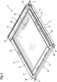
- the FIG. 1 shows a roof window 1, in particular a rooftop window.
- This has a frame 2 and a relative to the frame 2 movably mounted sash 3.
- the casement 3 carries a glazing 4 of the roof window 1.
- the window frame 2 is preferably fixedly mounted in a roof or the like.
- at least one fastening element 5 may be provided, which is present for example in the form of a mounting bracket.
- the fastener 5 is preferably bolted to both the frame 2 and the roof.
- the frame 2 consists of several spars, similar to a lower horizontal spar 6, an upper horizontal spar 7, a left vertical spar 8 and a right vertical spar 9.
- the wing frame 3 consists of a plurality of spars, which are not shown in detail here.
- the frame 2 and / or the sash 3, in particular their spars, for example, the spars 6, 7, 8 and 9, may be provided with at least one cover.
- the cover member serves to cover against an outside environment, so that environmental conditions can not negatively affect the roof window 1.
- an upper wellgelabdeckblech 10 As a cover, for example, one or more of the following elements may be present: an upper shegelabdeckblech 10, a water protection plate 11, upper rempligel.abdeckbleche 12, lower shegel.abdeckbleche 13 and side cover frame plates 14.
- the cover frame plates 14 close in the lateral direction of the copegel.abdeckbleche 12 and 13 at.
- the copegelabdeckblech 10 is connected by means of connecting elements 15 with the upper copetulin.abdeckblechen 12.
- the water protection plate 11 is connected via connecting elements 16 with the lower pogel.abdeckblechen 13.
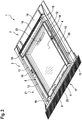
- the FIG. 2 shows the roof window 1 according to the above and cover 17, 18, 19 and 20.
- the cover 17, 18, 19 and 20 may be present, for example, as separately formed cover plates. In particular, they form a cover frame 21 for the roof window 1.
- the cover 21 and the cover 17, 18, 19 and 20 serve to discharge water from the roof window 1 in the direction of the roof.
- the cover element 17 has a cover skirt 22 which can be adapted to a shape or a structure of the roof.
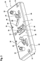
- FIG. 3 shows a locking device 24 of the roof window 1, which has at least one locking latch 25 which is arranged displaceably in a locking bolt receptacle 26.
- the locking device 24 is used to lock the roof window 1. It is preferably arranged on the casement 3 and actuated by the handle 23.
- the handle 23 serves to actuate the locking device 24 or to displace the locking bolt 25 in the locking bolt receptacle 26.
- the locking bolt 25 can assume a plurality of positions, in particular at least one locking position and a release position.
- the sash frame 3 In the locking position of the sash frame 3 is fixed relative to the frame 2 in its closed position. Thus, if the roof window 1 is locked or brought the locking latch 25 in the locking position, while the sash 3 is in its closed position, the sash 3 is set below in this. Accordingly, the roof window 1 can not be opened. This is only possible again when the locking bolt 25 is displaced into the release position. In this, the sash 3 is released to open the roof window 1.
- the locking device 24 or the locking bolt 25 preferably cooperates with a closing block 27 (not shown here), which is fastened to the window frame 2, for example.
- a closing block 27 (not shown here)
- the locking device 24 is arranged on the frame 2 and the closing block 27 on the sash 3.
- the locking bolt receptacle 26 is preferably formed in a base plate 28 of the locking device 24.
- the base plate 28 may be attached to a support frame 29 or at least partially received by this. Particularly preferably, the base plate 28 is clipped into the holding frame 29.
- at least one locking element 30 is provided, which holds the base plate 28 in a form-fitting manner on the holding frame 29.
- a plurality of locking elements 30, namely at least two locking elements 30, are provided.
- the holding frame 29 serves in particular for a spacing of the base plate 28 from a mounting surface (not shown), which may be present on the casement 3 or the frame 2.
- the locking device 24, in particular the base plate 28, by means of at least one screw to the sash 3 and the window frame 2 is fixed.
- the base plate 28 may have at least one screw hole 31 (here: three screw holes 31).
- the locking device 24 may be associated with at least one centering element 32 of a centering device 33.
- the at least one centering element 32 preferably interacts with a centering counter-element 34 (not illustrated here) when the roof window 1 is closed, in order to center the casement 3 with respect to the window frame 2. In this way, a particularly reliable and tight closure of the roof window on the one hand and a reliable locking using the locking device 24 on the other hand is achieved.
- the at least one centering counter-element 34 is preferably formed or arranged on the closing block 27.
- the at least one locking bolt 25, in the exemplary embodiment illustrated here, thus both locking bolt 25, are operatively connected to an actuating element 35, which is displaceable within an operating range.
- the actuating element 35 is arranged in a retaining recess 36 of the locking device 24.
- the retaining recess 36 is formed in the base plate 28, in particular edge-closed.
- the holding recess 36 is keyhole-shaped and thus has a wider insertion area 37 and a narrower holding area 38.
- the width of the insertion region 37 and of the holding region 38 is preferably in a direction which is perpendicular to a longitudinal central axis 39 of the holding recess 36 and lies in a plane defined by the extent of the base plate 28.
- the longitudinal central axis 39 preferably also corresponds to a displacement direction of the actuating element 35. This is thus held displaceable along the longitudinal central axis 39 in the retaining recess 36.
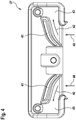
- FIG. 4 shows the closing block 27 of the roof window 1.
- the closing block 27 is preferably attached to the frame 2.
- the locking bolt 25 is inserted in the direction of the arrow 40 in the closing block 27. It may be provided that the closure latch 25 comes into contact with a guide projection 41.
- the guide projection 41 urges the locking bolt 25 in a further closing of the roof window 1 in the direction of the arrow 42, in particular in the lateral direction outwards until the locking bolt 25 is arranged in locking receptacle 43.
- the guide projection 41 thus urges the closure latch 25 when closing the roof window 1 from its release position into its locking position.
- the locking position of the locking latch 25 is in the Verrieglungsation 43, in which it is held positively.
- the roof window 1 can not be opened accordingly.
- the locking latch 25 In order to open the roof window 1 again, the locking latch 25 must be moved out of the locking receptacle 43, wherein this is provided opposite to the arrow 42 of the arrow. This displacement of the closure bar 25 can be achieved in particular by an actuation of the handle 23.
- the FIG. 5 shows a detailed view of the actuating element 35.
- the actuating element 35 has a wing region 45 with at least one wing 45, but preferably a plurality of wings 45 on. In the embodiment shown here, two wings 45 are provided.
- the wing area 44 is adjoined by a guide area 46 of the actuating element 35.
- On the wing 45 and on each wing 45 is a guide surface 47 before.
- This opposite is a support surface 48 formed on the actuating element 35.
- as many guide surfaces 47 as support surfaces 48 are provided on the actuating element 35, in particular two in each case.
- the actuating element 35 now has smaller dimensions in its wing region 44 than the insertion region 37 of the retaining recess 36, but at the same time larger than the retaining region 38. This is particularly preferably provided both in the lateral and in the axial direction (with respect to the here indicated longitudinal central axis 39 of the holding recess 36).
- the actuating element 35 has dimensions which are at most as large as the dimensions of the holding region 38, in particular in the lateral direction.
- the dimensions of the actuating element 35 in its guide region 46 correspond to the dimensions of the holding region 38 of the holding recess 36 in order to achieve reliable longitudinal guidance of the actuating element 35 in the holding recess 36.
- both the guide surface 47 and the support surface 48 are permanently on the base plate 28 at least partially, at least as long as the actuator 35 is within its operating range. Visible in the representation selected here is also a push rod receptacle 49 for a push rod 50, not shown here.
- FIG. 6 shows a frontal representation of the actuating element 35. It can be seen that the actuating element 35 has at least one bearing pin 51 on which a lever assembly (not shown) engages, via which the actuating element 35 is operatively connected to the closure latch 25. Furthermore, a fastening pin 52 is provided, on which, for example, a spring element, not shown here, is attached or acts.
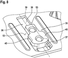
- FIG. 7 shows a detailed view of the arranged in the holding recess 36 actuating element 35.
- the actuating element 35 is present in an Betjanselementmontagegna, in which the wing portion 44 is disposed completely in the insertion region 37 of the holding recess 36. Because the wing region 44 has dimensions at least in the lateral direction which are smaller than the dimensions of the insertion region 37, the wing 45 or the vanes 45 can be introduced into the retaining recess 36 through the insertion region 37 and emerge from the latter on the opposite side. Thus, therefore, the guide portion 46 in the holding recess 36 before.
- the actuating element 35 is shown in the retaining recess 36, but in a different from the Betquestioned Trentselementmontagegna first position.
- the actuating element 35 is displaced along the longitudinal central axis 39 in the direction remote from the insertion region 37. Accordingly, the at least one wing 45 is no longer in the region of the insertion region 37. Rather, the guide portion 46, which is provided on the wing 45, on a mating guide surface 53 at.
- each guide surface 47 and consequently each vane 45 is assigned such a counter-guide surface 53. Accordingly, in each case on both sides of the holding recess 36 in each case before such a counter-guide surface 53. Due to the concerns of the guide surface 47 on the mating guide surface 53, the actuating element 35 can not get out of the holding recess 36.
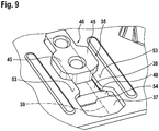
- FIG. 9 shows the arranged in the retaining recess 36 actuator 35 in a second position, which also of the Betreli whyselementmontagegna is different.
- the actuator 35 is located further from the actuator assembly position than in the first position.
- the support surface 48 can be recognized at least in the beginning. This is applied to a mating support surface 54 of the base plate 28.
- the counter guide surface 53 and the counter support surface 54 are arranged on opposite sides of the base plate 28.
- the base plate 28 is thus arranged between the guide surface 47 and the support surface 48 of the actuating element 35, so that the actuating element 35 is held securely on the base plate 28 as long as it is in its operating region.
- the Betx Trentselementmontagegna lies outside the operating range.
- FIG. 10 shows a side sectional view of the locking device 24.
- the actuating element 35 can be seen.
- the push rod 50 is arranged in the push rod receptacle 49.
- the push rod receptacle 49 has a bearing eye 55 and a guide opening 56.
- the guide opening 56 and thus the push rod receptacle 49 are formed open-edge in the fastener 35.
- the push rod 50 in particular a push rod attachment member 57 in the bearing eye 55 can be introduced, provided that the push rod 50 is present in a push rod mounting angle position. This one is shown here.
- FIG. 11 again shows the side sectional view of the locking device 24.
- the push rod attachment member 57 is configured such that when the push rod is arranged in the push rod mounting angle position it can pass into or through the guide opening 56, both in the direction of the bearing eye 55 and out of it.
- the push rod attachment member 57 is configured such that it can not pass into or through the guide opening 56 at an angular position of the push rod 50, which is different from the push rod mounting angle position, for example, the push rod operating angle position. Accordingly, in the push rod operating angle position shown here, the push rod 59 or its push rod fastening element 57 is securely held in the bearing eye 55.
- FIG. 12 shows a detailed view of a portion of the push rod 50.
- the push rod attachment member 57 is shown, which is in the form of a web at a free end of the push rod 50 is formed.
- Adjacent to the push rod attachment member 57 is a recess 58, preferably closed at the edge, formed in the push rod 50. In this can engage the actuator 35 at least partially to the arrangement of the push rod 50 in the push rod operating angle position.
- the push rod attachment member 57 by its engagement in the push rod receptacle 59 and the actuator 35 by engaging in the recess 58 a positive connection between the actuator 35 and the push rod 50 ago.
- Edges of the push rod attachment member 57 are preferably each provided with a rounding 59 or at least one phase.
- the radius of the rounding preferably corresponds to the radius of the bearing eye 55 to allow a displacement of the push rod 50 or a tilting of the push rod 50 from the push rod mounting angle position in the push rod operating angle position without entanglement or with low resistance.
- FIG. 13 illustrates the function of the above-mentioned centering device 33 with the at least one centering element 32.
- the centering counter-element 34 should be provided on the closing block 27, which, for example by means of screws 60, preferably attached to the frame 2.
- the centering counter-element 34 is present here in the form of a centering surface, which is provided in the inlet direction of the centering element 32 with an inclined run-on slope or a rounding 61.
- the centering device 33 is shown with the roof window 1 still partially open.
- FIG. 14 again shows the centering device 33, but the roof window 1 is completely closed. It becomes clear that the centering elements 32 now receive the centering counter-element 34 between them and thus center. In a deflection of the sash 3 with respect to the frame 2 in the lateral direction, the rounding 61 or bevel provides for a reliable centering of the sash frame 3 with respect to the frame 2.
- the integrated design of the centering device 3 with the locking device 24 and the closing block 27, this centering is realized with an extremely low cost. In particular, no additional devices to be provided on the roof window 1.
Landscapes
- Engineering & Computer Science (AREA)
- Architecture (AREA)
- Civil Engineering (AREA)
- Structural Engineering (AREA)
- Mechanical Engineering (AREA)
- Wing Frames And Configurations (AREA)
- Power-Operated Mechanisms For Wings (AREA)
Claims (10)
- Fenêtre de toit (1), notamment fenêtre de toit d'habitation, comprenant un cadre dormant (2), un cadre battant (3) ainsi qu'un dispositif de verrouillage (24) qui présente au moins un verrou de fermeture (25), lequel, dans une position de verrouillage, fixe le cadre battant (3) en une position fermée par rapport au cadre dormant (2), et, dans une position de libération, le libère pour l'ouverture de la fenêtre de toit (1), dans laquelle l'au moins un verrou de fermeture (25) est relié opérationnellement à un élément d'actionnement (35) déplaçable à l'intérieur d'une zone d'actionnement, caractérisée en ce que l'élément d'actionnement (35), dans une position de montage de l'élément d'actionnement située en dehors de la zone d'actionnement, peut être mis dans un évidement de maintien (36), en forme de trou de serrure, du dispositif de verrouillage (24) et en ce qu'à l'intérieur de la zone d'actionnement, il est maintenu de manière imperdable dans l'évidement de maintien (36), dans laquelle une tige de poussée (50) est fixée sur l'élément d'actionnement (35), laquelle tige de poussée présente un élément de fixation (57) de tige de poussée, qui, dans une position angulaire de montage de la tige de poussée, peut être mis dans un logement (49) de tige de poussée de l'élément d'actionnement (35) et, dans une position angulaire de fonctionnement de la tige de poussée, est maintenu dans le logement (49) de tige de poussée.
- Fenêtre de toit selon la revendication 1, caractérisée en ce que l'évidement de maintien (36) présente une zone d'insertion (37) plus large et une zone de maintien (38) plus étroite, dans laquelle l'élément d'actionnement (35) présente au moins une zone d'ailette (44) dans laquelle il présente des dimensions plus petites que la zone d'insertion (37) et des dimensions plus grandes que la zone de maintien (38).
- Fenêtre de toit selon l'une quelconque des revendications précédentes, caractérisée en ce qu'une zone de guidage (46) de l'élément d'actionnement (35) se raccorde à la zone d'ailette (44), laquelle zone de guidage présente des dimensions qui sont au maximum aussi grandes que les dimensions de la zone de maintien (38).
- Fenêtre de toit selon l'une quelconque des revendications précédentes, caractérisée en ce que l'élément d'actionnement (35) présente dans la zone d'ailette (44) au moins une ailette (45) sur laquelle une surface de guidage (47) est présente qui - lorsque l'élément d'actionnement (35) est disposé dans la zone d'actionnement - est en contact coulissant avec une contre-surface de guidage (53) du dispositif de verrouillage (24).
- Fenêtre de toit selon l'une quelconque des revendications précédentes, caractérisée en ce que l'évidement de maintien (36) est présent dans une plaque de base (28) du dispositif de verrouillage (24).
- Fenêtre de toit selon l'une quelconque des revendications précédentes, caractérisée en ce que l'élément d'actionnement (35) présente sur le côté opposé à l'ailette (45) par rapport à la plaque de base (28) une surface d'appui (48) qui est en contact coulissant avec une contre-surface d'appui (54) présente sur la plaque de base (28).
- Fenêtre de toit selon l'une quelconque des revendications précédentes, caractérisée en ce que le logement (49) de tige de poussée présente un oeillet (55) et une ouverture de guidage (56) débouchant dans l'oeillet (55), dans laquelle l'oeillet (55) présente un diamètre qui est plus petit que la largeur de l'ouverture de guidage (56), et dans laquelle l'élément de fixation (57) de tige de poussée présente une épaisseur plus petite que la largeur de l'ouverture de guidage (56) et une largeur plus grande que la largeur de l'ouverture de guidage (56).
- Fenêtre de toit selon l'une quelconque des revendications précédentes, caractérisée en ce que la plaque de base (28) est clipsée sur un cadre de maintien (29).
- Fenêtre de toit selon l'une quelconque des revendications précédentes, caractérisée en ce qu'au moins un élément de centrage (32) d'un dispositif de centrage (33) est associé au dispositif de verrouillage (24), lequel élément de centrage, lors d'une fermeture de la fenêtre de toit (1), coopère avec un contre-élément de centrage (34) disposé sur un bloc de fermeture (27) de la fenêtre de toit (1), destiné au centrage du cadre battant (3) par rapport au cadre dormant (2).
- Procédé de montage d'une fenêtre de toit (1) selon l'une quelconque ou plusieurs des revendications précédentes, dans lequel la fenêtre de toit (1) dispose d'un cadre dormant (2), d'un cadre battant (3) ainsi que d'un dispositif de verrouillage (24) présentant au moins un verrou de fermeture (25) qui, dans une position de verrouillage, fixe le cadre battant (3) en une position fermée par rapport au cadre dormant (2), et, dans une position de libération, le libère pour l'ouverture de la fenêtre de toit (1), dans lequel l'au moins un verrou de fermeture (25) est relié opérationnellement à un élément d'actionnement (35) déplaçable à l'intérieur d'une zone d'actionnement, caractérisé en ce que l'élément d'actionnement (35), dans une position de montage de l'élément d'actionnement située en dehors de la zone d'actionnement, est mis dans un évidement de maintien (36), en forme de trou de serrure, du dispositif de verrouillage (24) et en ce qu'à l'intérieur de la zone d'actionnement, il est maintenu de manière imperdable dans l'évidement de maintien (36), dans lequel une tige de poussée (50) est fixée sur l'élément d'actionnement (35), laquelle tige de poussée présente un élément de fixation (57) de tige de poussée, qui, dans une position angulaire de montage de la tige de poussée, est mis dans un logement (49) de tige de poussée de l'élément d'actionnement (35) et, dans une position angulaire de fonctionnement de la tige de poussée, est maintenu dans le logement (49) de tige de poussée.
Priority Applications (1)
| Application Number | Priority Date | Filing Date | Title |
|---|---|---|---|
| PL15168661T PL2947221T3 (pl) | 2014-05-22 | 2015-05-21 | Okno dachowe, jak też sposób montowania okna dachowego |
Applications Claiming Priority (1)
| Application Number | Priority Date | Filing Date | Title |
|---|---|---|---|
| DE102014007841.8A DE102014007841A1 (de) | 2014-05-22 | 2014-05-22 | Dachfenster sowie Verfahren zum Montieren eines Dachfensters |
Publications (2)
| Publication Number | Publication Date |
|---|---|
| EP2947221A1 EP2947221A1 (fr) | 2015-11-25 |
| EP2947221B1 true EP2947221B1 (fr) | 2017-02-01 |
Family
ID=53268664
Family Applications (1)
| Application Number | Title | Priority Date | Filing Date |
|---|---|---|---|
| EP15168661.5A Active EP2947221B1 (fr) | 2014-05-22 | 2015-05-21 | Fenêtre de toit et procédé de montage d'une fenêtre de toit |
Country Status (3)
| Country | Link |
|---|---|
| EP (1) | EP2947221B1 (fr) |
| DE (1) | DE102014007841A1 (fr) |
| PL (1) | PL2947221T3 (fr) |
Families Citing this family (3)
| Publication number | Priority date | Publication date | Assignee | Title |
|---|---|---|---|---|
| GB201609935D0 (en) * | 2016-06-07 | 2016-07-20 | Keylite Roof Windows Ltd | A ventilation apparatus for a roof window |
| DE102016212600A1 (de) * | 2016-07-11 | 2018-01-11 | Roto Frank Ag | Verriegelungseinrichtung für einen Gebäudeverschluss, entsprechender Gebäudeverschluss, Montagesatz zur Herstellung von Gebäudeverschlüssen sowie Verfahren zum Ausrüsten eines Gebäudeverschlusses |
| DK180431B1 (en) * | 2018-09-24 | 2021-04-23 | Vkr Holding As | A roof window with an improved lock casing |
Family Cites Families (6)
| Publication number | Priority date | Publication date | Assignee | Title |
|---|---|---|---|---|
| DE1259060B (de) * | 1963-11-20 | 1968-01-18 | Wilhelm Hachtel | Vorhangtraeger mit mehreren hintereinander angeordneten Gleitfluegel- oder Rollenpaaren |
| DE1927378U (de) * | 1965-09-21 | 1965-11-18 | E L Hirz K G | Dachfenster. |
| DE2815484B2 (de) * | 1978-04-10 | 1980-02-28 | Fa. Hans Kloeber, 5828 Ennepetal | Feststellvorrichtung für Fenster, insbesondere Dachfenster |
| EP1508663B1 (fr) * | 2003-08-20 | 2006-08-09 | VKR Holding A/S | Une fenêtre pivotante améliorée avec au moins un dispositif auxiliaire d'ouverture |
| WO2012034558A1 (fr) * | 2010-09-16 | 2012-03-22 | Vkr Holding A/S | Ensemble de verrouillage |
| EP2565355B1 (fr) * | 2011-09-01 | 2018-07-18 | VKR Holding A/S | Ensemble de fenêtre muni d'une poignée encliquetable et procédé permettant de transporter l'ensemble de fenêtre |
-
2014
- 2014-05-22 DE DE102014007841.8A patent/DE102014007841A1/de not_active Withdrawn
-
2015
- 2015-05-21 PL PL15168661T patent/PL2947221T3/pl unknown
- 2015-05-21 EP EP15168661.5A patent/EP2947221B1/fr active Active
Also Published As
| Publication number | Publication date |
|---|---|
| EP2947221A1 (fr) | 2015-11-25 |
| PL2947221T3 (pl) | 2017-07-31 |
| DE102014007841A1 (de) | 2015-12-17 |
Similar Documents
| Publication | Publication Date | Title |
|---|---|---|
| EP1709270B1 (fr) | Fixation de pinces pour le montage de dispositifs de ferrures, tels que fermetures, elements de charniere, poignees dans des passages au travers d'une paroi mince | |
| EP3504391B1 (fr) | Ensemble charnière pour un boitier d'armoire électrique et un boitier d'armoire électrique correspondant | |
| EP3102759B1 (fr) | Ferrure d'un battant de fenêtres ou de portes, au moins relevable et coulissant | |
| EP3676468B1 (fr) | Dispositif de fermeture pour armoire électrique et armoire électrique correspondante | |
| DE102007017453B4 (de) | Drehöffnungsbegrenzungsvorrichtung für einen Flügel eines Fensters oder dergleichen | |
| EP2947239B1 (fr) | Système d'actionnement pour une fermeture de bâtiment et fermeture de bâtiment dotée d'un système d'actionnement | |
| EP2947221A1 (fr) | Fenêtre de toit et procédé de montage d'une fenêtre de toit | |
| EP3055472B1 (fr) | Ferrure d'un battant de fenêtres ou de portes au moins relevables, mais de préférence également coulissants | |
| WO2017157611A1 (fr) | Dispositif de projection du battant d'une fenêtre ou d'une porte qui peut être amené au moins dans une position de rangement parallèle et qui est apte à coulisser horizontalement dans cette position | |
| WO2019166264A1 (fr) | Dispositif pour recouvrir un ouvrant coulissant ou un ouvrant coulissant et levant pouvant être déplacé d'une fenêtre ou d'une porte | |
| EP4146888B1 (fr) | Ensemble charnière à actionnement commun | |
| DE102020107002A1 (de) | Verschluss mit Anschlagsadapter | |
| EP2171177A1 (fr) | Élément de recouvrement pour opérations de maintenance | |
| EP3556973A2 (fr) | Fermeture | |
| DE102022113577A1 (de) | Stangenverschluss | |
| WO2017178221A1 (fr) | Ferrure de deux battants de fenêtres ou de portes, aptes au moins à être levés ou à coulisser | |
| EP3269902B1 (fr) | Ensemble d'actionnement pour une fermeture de bâtiment, fermeture de bâtiment correspondante, kit de montage destiné à produire des fermetures de bâtiments et procédé d'équipement d'une fermeture de bâtiment | |
| EP2947223B1 (fr) | Système de poignée pivotante de fenêtre de toit d'habitation, fenêtre de toit équipée d'un système de poignée pivotante, ainsi que procédé d'installation d'une fenêtre de toit | |
| EP3103947B1 (fr) | Fermeture d'une ferrure | |
| DE102014111131A1 (de) | Vorrichtung zur Ver- und Entriegelung eines Fensterflügels, einer Lüftungsklappe oder dergleichen an einem Blendrahmen | |
| DE19809900B4 (de) | Vorrichtung zur Sicherung von Fenster, Fenstertüren und Türen gegen gewaltsames Öffnen | |
| EP3235984A1 (fr) | Ferrure de fenêtre, son procédé de fabrication et fenêtre correspondante | |
| EP2861811B1 (fr) | Fenêtre, porte ou similaire comprenant un profilé de fermeture | |
| EP2899348B1 (fr) | Dispositif d'appui pour un battant d'une fenêtre ou d'une porte | |
| EP2947228A1 (fr) | Fenêtre de toit |
Legal Events
| Date | Code | Title | Description |
|---|---|---|---|
| PUAI | Public reference made under article 153(3) epc to a published international application that has entered the european phase |
Free format text: ORIGINAL CODE: 0009012 |
|
| AK | Designated contracting states |
Kind code of ref document: A1 Designated state(s): AL AT BE BG CH CY CZ DE DK EE ES FI FR GB GR HR HU IE IS IT LI LT LU LV MC MK MT NL NO PL PT RO RS SE SI SK SM TR |
|
| AX | Request for extension of the european patent |
Extension state: BA ME |
|
| 17P | Request for examination filed |
Effective date: 20160525 |
|
| RBV | Designated contracting states (corrected) |
Designated state(s): AL AT BE BG CH CY CZ DE DK EE ES FI FR GB GR HR HU IE IS IT LI LT LU LV MC MK MT NL NO PL PT RO RS SE SI SK SM TR |
|
| GRAP | Despatch of communication of intention to grant a patent |
Free format text: ORIGINAL CODE: EPIDOSNIGR1 |
|
| INTG | Intention to grant announced |
Effective date: 20160831 |
|
| GRAS | Grant fee paid |
Free format text: ORIGINAL CODE: EPIDOSNIGR3 |
|
| GRAA | (expected) grant |
Free format text: ORIGINAL CODE: 0009210 |
|
| AK | Designated contracting states |
Kind code of ref document: B1 Designated state(s): AL AT BE BG CH CY CZ DE DK EE ES FI FR GB GR HR HU IE IS IT LI LT LU LV MC MK MT NL NO PL PT RO RS SE SI SK SM TR |
|
| REG | Reference to a national code |
Ref country code: GB Ref legal event code: FG4D Free format text: NOT ENGLISH |
|
| REG | Reference to a national code |
Ref country code: CH Ref legal event code: EP Ref country code: AT Ref legal event code: REF Ref document number: 865743 Country of ref document: AT Kind code of ref document: T Effective date: 20170215 |
|
| REG | Reference to a national code |
Ref country code: IE Ref legal event code: FG4D Free format text: LANGUAGE OF EP DOCUMENT: GERMAN |
|
| REG | Reference to a national code |
Ref country code: DE Ref legal event code: R096 Ref document number: 502015000547 Country of ref document: DE |
|
| REG | Reference to a national code |
Ref country code: CH Ref legal event code: NV Representative=s name: OFFICE ERNEST T. FREYLINGER S.A., CH |
|
| REG | Reference to a national code |
Ref country code: FR Ref legal event code: PLFP Year of fee payment: 3 |
|
| REG | Reference to a national code |
Ref country code: NL Ref legal event code: MP Effective date: 20170201 |
|
| REG | Reference to a national code |
Ref country code: LT Ref legal event code: MG4D |
|
| PG25 | Lapsed in a contracting state [announced via postgrant information from national office to epo] |
Ref country code: GR Free format text: LAPSE BECAUSE OF FAILURE TO SUBMIT A TRANSLATION OF THE DESCRIPTION OR TO PAY THE FEE WITHIN THE PRESCRIBED TIME-LIMIT Effective date: 20170502 Ref country code: IS Free format text: LAPSE BECAUSE OF FAILURE TO SUBMIT A TRANSLATION OF THE DESCRIPTION OR TO PAY THE FEE WITHIN THE PRESCRIBED TIME-LIMIT Effective date: 20170601 Ref country code: HR Free format text: LAPSE BECAUSE OF FAILURE TO SUBMIT A TRANSLATION OF THE DESCRIPTION OR TO PAY THE FEE WITHIN THE PRESCRIBED TIME-LIMIT Effective date: 20170201 Ref country code: NO Free format text: LAPSE BECAUSE OF FAILURE TO SUBMIT A TRANSLATION OF THE DESCRIPTION OR TO PAY THE FEE WITHIN THE PRESCRIBED TIME-LIMIT Effective date: 20170501 Ref country code: FI Free format text: LAPSE BECAUSE OF FAILURE TO SUBMIT A TRANSLATION OF THE DESCRIPTION OR TO PAY THE FEE WITHIN THE PRESCRIBED TIME-LIMIT Effective date: 20170201 Ref country code: LT Free format text: LAPSE BECAUSE OF FAILURE TO SUBMIT A TRANSLATION OF THE DESCRIPTION OR TO PAY THE FEE WITHIN THE PRESCRIBED TIME-LIMIT Effective date: 20170201 |
|
| PG25 | Lapsed in a contracting state [announced via postgrant information from national office to epo] |
Ref country code: SE Free format text: LAPSE BECAUSE OF FAILURE TO SUBMIT A TRANSLATION OF THE DESCRIPTION OR TO PAY THE FEE WITHIN THE PRESCRIBED TIME-LIMIT Effective date: 20170201 Ref country code: BG Free format text: LAPSE BECAUSE OF FAILURE TO SUBMIT A TRANSLATION OF THE DESCRIPTION OR TO PAY THE FEE WITHIN THE PRESCRIBED TIME-LIMIT Effective date: 20170501 Ref country code: NL Free format text: LAPSE BECAUSE OF NON-PAYMENT OF DUE FEES Effective date: 20170201 Ref country code: LU Free format text: LAPSE BECAUSE OF NON-PAYMENT OF DUE FEES Effective date: 20170531 Ref country code: RS Free format text: LAPSE BECAUSE OF FAILURE TO SUBMIT A TRANSLATION OF THE DESCRIPTION OR TO PAY THE FEE WITHIN THE PRESCRIBED TIME-LIMIT Effective date: 20170201 Ref country code: LV Free format text: LAPSE BECAUSE OF FAILURE TO SUBMIT A TRANSLATION OF THE DESCRIPTION OR TO PAY THE FEE WITHIN THE PRESCRIBED TIME-LIMIT Effective date: 20170201 Ref country code: ES Free format text: LAPSE BECAUSE OF FAILURE TO SUBMIT A TRANSLATION OF THE DESCRIPTION OR TO PAY THE FEE WITHIN THE PRESCRIBED TIME-LIMIT Effective date: 20170201 Ref country code: PT Free format text: LAPSE BECAUSE OF FAILURE TO SUBMIT A TRANSLATION OF THE DESCRIPTION OR TO PAY THE FEE WITHIN THE PRESCRIBED TIME-LIMIT Effective date: 20170601 |
|
| PG25 | Lapsed in a contracting state [announced via postgrant information from national office to epo] |
Ref country code: SK Free format text: LAPSE BECAUSE OF FAILURE TO SUBMIT A TRANSLATION OF THE DESCRIPTION OR TO PAY THE FEE WITHIN THE PRESCRIBED TIME-LIMIT Effective date: 20170201 Ref country code: RO Free format text: LAPSE BECAUSE OF FAILURE TO SUBMIT A TRANSLATION OF THE DESCRIPTION OR TO PAY THE FEE WITHIN THE PRESCRIBED TIME-LIMIT Effective date: 20170201 Ref country code: EE Free format text: LAPSE BECAUSE OF FAILURE TO SUBMIT A TRANSLATION OF THE DESCRIPTION OR TO PAY THE FEE WITHIN THE PRESCRIBED TIME-LIMIT Effective date: 20170201 |
|
| REG | Reference to a national code |
Ref country code: DE Ref legal event code: R097 Ref document number: 502015000547 Country of ref document: DE |
|
| PG25 | Lapsed in a contracting state [announced via postgrant information from national office to epo] |
Ref country code: DK Free format text: LAPSE BECAUSE OF FAILURE TO SUBMIT A TRANSLATION OF THE DESCRIPTION OR TO PAY THE FEE WITHIN THE PRESCRIBED TIME-LIMIT Effective date: 20170201 Ref country code: SM Free format text: LAPSE BECAUSE OF FAILURE TO SUBMIT A TRANSLATION OF THE DESCRIPTION OR TO PAY THE FEE WITHIN THE PRESCRIBED TIME-LIMIT Effective date: 20170201 |
|
| PLBE | No opposition filed within time limit |
Free format text: ORIGINAL CODE: 0009261 |
|
| STAA | Information on the status of an ep patent application or granted ep patent |
Free format text: STATUS: NO OPPOSITION FILED WITHIN TIME LIMIT |
|
| 26N | No opposition filed |
Effective date: 20171103 |
|
| PG25 | Lapsed in a contracting state [announced via postgrant information from national office to epo] |
Ref country code: MC Free format text: LAPSE BECAUSE OF FAILURE TO SUBMIT A TRANSLATION OF THE DESCRIPTION OR TO PAY THE FEE WITHIN THE PRESCRIBED TIME-LIMIT Effective date: 20170201 |
|
| REG | Reference to a national code |
Ref country code: IE Ref legal event code: MM4A |
|
| PG25 | Lapsed in a contracting state [announced via postgrant information from national office to epo] |
Ref country code: SI Free format text: LAPSE BECAUSE OF FAILURE TO SUBMIT A TRANSLATION OF THE DESCRIPTION OR TO PAY THE FEE WITHIN THE PRESCRIBED TIME-LIMIT Effective date: 20170201 |
|
| PG25 | Lapsed in a contracting state [announced via postgrant information from national office to epo] |
Ref country code: LU Free format text: LAPSE BECAUSE OF NON-PAYMENT OF DUE FEES Effective date: 20170521 |
|
| REG | Reference to a national code |
Ref country code: BE Ref legal event code: MM Effective date: 20170531 |
|
| PG25 | Lapsed in a contracting state [announced via postgrant information from national office to epo] |
Ref country code: IE Free format text: LAPSE BECAUSE OF NON-PAYMENT OF DUE FEES Effective date: 20170521 |
|
| REG | Reference to a national code |
Ref country code: FR Ref legal event code: PLFP Year of fee payment: 4 |
|
| PG25 | Lapsed in a contracting state [announced via postgrant information from national office to epo] |
Ref country code: BE Free format text: LAPSE BECAUSE OF NON-PAYMENT OF DUE FEES Effective date: 20170531 |
|
| PGFP | Annual fee paid to national office [announced via postgrant information from national office to epo] |
Ref country code: IT Payment date: 20180531 Year of fee payment: 4 |
|
| PG25 | Lapsed in a contracting state [announced via postgrant information from national office to epo] |
Ref country code: MT Free format text: LAPSE BECAUSE OF FAILURE TO SUBMIT A TRANSLATION OF THE DESCRIPTION OR TO PAY THE FEE WITHIN THE PRESCRIBED TIME-LIMIT Effective date: 20170201 |
|
| PG25 | Lapsed in a contracting state [announced via postgrant information from national office to epo] |
Ref country code: HU Free format text: LAPSE BECAUSE OF FAILURE TO SUBMIT A TRANSLATION OF THE DESCRIPTION OR TO PAY THE FEE WITHIN THE PRESCRIBED TIME-LIMIT; INVALID AB INITIO Effective date: 20150521 |
|
| PG25 | Lapsed in a contracting state [announced via postgrant information from national office to epo] |
Ref country code: CY Free format text: LAPSE BECAUSE OF FAILURE TO SUBMIT A TRANSLATION OF THE DESCRIPTION OR TO PAY THE FEE WITHIN THE PRESCRIBED TIME-LIMIT Effective date: 20170201 |
|
| PG25 | Lapsed in a contracting state [announced via postgrant information from national office to epo] |
Ref country code: MK Free format text: LAPSE BECAUSE OF FAILURE TO SUBMIT A TRANSLATION OF THE DESCRIPTION OR TO PAY THE FEE WITHIN THE PRESCRIBED TIME-LIMIT Effective date: 20170201 |
|
| PG25 | Lapsed in a contracting state [announced via postgrant information from national office to epo] |
Ref country code: TR Free format text: LAPSE BECAUSE OF FAILURE TO SUBMIT A TRANSLATION OF THE DESCRIPTION OR TO PAY THE FEE WITHIN THE PRESCRIBED TIME-LIMIT Effective date: 20170201 |
|
| PG25 | Lapsed in a contracting state [announced via postgrant information from national office to epo] |
Ref country code: IT Free format text: LAPSE BECAUSE OF NON-PAYMENT OF DUE FEES Effective date: 20190521 |
|
| PG25 | Lapsed in a contracting state [announced via postgrant information from national office to epo] |
Ref country code: AL Free format text: LAPSE BECAUSE OF FAILURE TO SUBMIT A TRANSLATION OF THE DESCRIPTION OR TO PAY THE FEE WITHIN THE PRESCRIBED TIME-LIMIT Effective date: 20170201 |
|
| PGFP | Annual fee paid to national office [announced via postgrant information from national office to epo] |
Ref country code: PL Payment date: 20250513 Year of fee payment: 11 Ref country code: DE Payment date: 20250519 Year of fee payment: 11 |
|
| PGFP | Annual fee paid to national office [announced via postgrant information from national office to epo] |
Ref country code: GB Payment date: 20250522 Year of fee payment: 11 |
|
| PGFP | Annual fee paid to national office [announced via postgrant information from national office to epo] |
Ref country code: FR Payment date: 20250526 Year of fee payment: 11 |
|
| PGFP | Annual fee paid to national office [announced via postgrant information from national office to epo] |
Ref country code: CH Payment date: 20250601 Year of fee payment: 11 |
|
| PGFP | Annual fee paid to national office [announced via postgrant information from national office to epo] |
Ref country code: AT Payment date: 20250519 Year of fee payment: 11 |
|
| PGFP | Annual fee paid to national office [announced via postgrant information from national office to epo] |
Ref country code: CZ Payment date: 20250509 Year of fee payment: 11 |