EP2947242A1 - Schiebetüranordnung - Google Patents
Schiebetüranordnung Download PDFInfo
- Publication number
- EP2947242A1 EP2947242A1 EP14168883.8A EP14168883A EP2947242A1 EP 2947242 A1 EP2947242 A1 EP 2947242A1 EP 14168883 A EP14168883 A EP 14168883A EP 2947242 A1 EP2947242 A1 EP 2947242A1
- Authority
- EP
- European Patent Office
- Prior art keywords
- locking bolt
- sliding door
- frame
- locking
- bolt
- Prior art date
- Legal status (The legal status is an assumption and is not a legal conclusion. Google has not performed a legal analysis and makes no representation as to the accuracy of the status listed.)
- Granted
Links
Images


Classifications
-
- E—FIXED CONSTRUCTIONS
- E05—LOCKS; KEYS; WINDOW OR DOOR FITTINGS; SAFES
- E05B—LOCKS; ACCESSORIES THEREFOR; HANDCUFFS
- E05B15/00—Other details of locks; Parts for engagement by bolts of fastening devices
- E05B15/02—Striking-plates; Keepers; Bolt staples; Escutcheons
- E05B15/0205—Striking-plates, keepers, staples
- E05B15/024—Striking-plates, keepers, staples adjustable
-
- E—FIXED CONSTRUCTIONS
- E05—LOCKS; KEYS; WINDOW OR DOOR FITTINGS; SAFES
- E05B—LOCKS; ACCESSORIES THEREFOR; HANDCUFFS
- E05B65/00—Locks or fastenings for special use
- E05B65/08—Locks or fastenings for special use for sliding wings
-
- E—FIXED CONSTRUCTIONS
- E05—LOCKS; KEYS; WINDOW OR DOOR FITTINGS; SAFES
- E05B—LOCKS; ACCESSORIES THEREFOR; HANDCUFFS
- E05B17/00—Accessories in connection with locks
- E05B17/20—Means independent of the locking mechanism for preventing unauthorised opening, e.g. for securing the bolt in the fastening position
- E05B17/2084—Means to prevent forced opening by attack, tampering or jimmying
- E05B17/2088—Means to prevent disengagement of lock and keeper
-
- E—FIXED CONSTRUCTIONS
- E05—LOCKS; KEYS; WINDOW OR DOOR FITTINGS; SAFES
- E05B—LOCKS; ACCESSORIES THEREFOR; HANDCUFFS
- E05B15/00—Other details of locks; Parts for engagement by bolts of fastening devices
- E05B15/02—Striking-plates; Keepers; Bolt staples; Escutcheons
- E05B15/0205—Striking-plates, keepers, staples
- E05B2015/023—Keeper shape
- E05B2015/0235—Stud-like
Definitions
- the invention relates to a sliding door assembly, comprising a stationary frame, a horizontally displaceable door leaf and a locking device for locking the door leaf on the frame, wherein the locking device has a locking bolt and a cooperating with the locking bolt pin receptacle.
- a sliding door arrangement of the type mentioned is from the DE 26 03 240 A1 known.
- Sliding door assemblies or tilt-and-slide door assemblies that are used as part of building glazing employ locking devices that include a latch bolt and a bolt receptacle cooperating with the latch bolt. These can be brought into a closed position locking the hinged door and into a release position which releases the hinged door.
- locking bolt and bolt receptacle can not be sufficiently aligned or aligned with each other, so that they meet when opening and / or closing the sliding door with increased wear on each other, but at least touch each other, and only then "aligned". This leads to noticeable handling problems for the user due to noticeable jerking. Due to the increased wear a permanent and reliable operation is not guaranteed. Manual rework by machining, for example a filing of the locking bolt, is not reversible and weakens the machined elements.
- the present invention is therefore based on the object, a sliding door assembly of the type mentioned in such a way and further, that a comfortable and durable reliable use is possible.
- the locking bolt is adjustable in at least a first adjustment direction of a plane, wherein the normal vector of the plane is defined by the direction of displacement of the door leaf.
- the locking bolt and cooperating with the locking bolt bolt receptacle of the locking device are not only mounted on the sliding door assembly, but in their position relative to each other adaptable.
- the locking bolt in at least a first direction of a plane, namely a first adjustment direction of a plane adjustable.
- the normal vector of this plane is defined by the sliding direction of the door leaf.
- the adjustment of the locking bolt enabling mimic can also be referred to as adjustment.
- adjustment the alignment between the locking bolt and the bolt receptacle accommodating the locking bolt for closing the sliding door arrangement can be adjusted in a simple manner.
- Manufacturing tolerances can be compensated. Due to the possible adjustability of the locking bolt after assembly of the locking device whose assembly and thus the assembly of the sliding door assembly is significantly simplified overall. Possible assembly errors can be easily corrected.
- the first adjustment direction of the locking bolt is oriented orthogonal to a plane formed by the frame. This allows latch bolt and bolt receptacle "aligned" relative to each other, in - in the direction of displacement of the door leaf - lateral direction. As a result, misalignments, for example due to assembly errors, can be cleared out in the lateral direction.
- the installation angle of the bolt can also be corrected, at least to a small extent.
- the first adjustment direction of the locking bolt is located in a plane formed by the frame and oriented orthogonal to the direction of displacement of the door leaf. In this way, corrections of the alignment of locking bolts and bolt receptacle in - relative to the installation position of the stationary frame - vertical direction possible.
- the locking bolt having plate-like sections with passages in the form of slots and is adjustably connected by means of introduced into the slots mounting screws with the frame. This can be done by adjusting the positions of the locking bolt in the adjustment direction alignment of locking bolt and bolt receptacle.
- the longitudinal direction of the oblong holes coincides with the setting direction.
- a simple adjustment of the locking bolt can be done, namely by loosening the mounting screws, positioning the locking bolt and then tightening the mounting screws.
- a simple handling of the setting is realized.
- the locking bolt is adjustable in a second adjustment direction of the plane whose normal vector is defined by the direction of displacement of the door leaf and in that the second adjustment direction is oriented orthogonal to the first adjustment direction.
- the adjustability of the locking bolt is not limited to a setting in one direction, but can be a positioning of the locking bolt in two directions.
- the locking bolt is adjustable within a plane section. In other words, the locking bolt can be adjusted relative to the frame in its lateral position and its height. Mounting errors in - related to the installation position of the locking bolt - lateral and vertical direction can be corrected.
- the locking bolt For a particularly stable attachment of the locking bolt with structurally simple means of the locking bolt by means of a separately provided base plate with Passages and attached by means of these passages fastening screws attached to the frame.
- the locking bolt itself is not attached directly to the frame, but by means of a base plate.
- the locking bolt is secured to the base plate via the passages in the plate-like sections.
- the assembly is considerably simplified due to the predetermined in at least one direction, for example, the second adjustment direction, the position of the locking bolt.
- the passages of the base plate are formed as elongated holes and aligned such that the base plate along the second adjustment direction of the locking bolt is adjustable.
- an adjustment is given with structurally simple means, which is only slightly adjustable in one direction by slightly loosening the mounting screws of the base plate. For a setting with easy handling can be realized.
- the locking bolt is additionally adjustable in the direction of displacement of the door leaf. This can not only make an adjustment of locking bolt and bolt receptacle in lateral position and / or height, but can be done by adjusting the locking bolt in wing sliding direction defined closing the door leaf.
- the seal between the door and the frame can be adjusted with simple structural means.
- Base plate further passages are formed, which have an internal thread, and that by means of introduced into these passages screws the distance between the frame and the base plate is adjustable.
- This is a simple and space-saving adjusting device realized.
- adjusting screws may be a particularly space-saving design around grub screws.
- the plate-like portions of the locking bolt have a width which is smaller than a width of the base plate at least by the amount of the realized through the slots of the locking bolt adjustment range. In this way, an unhindered adjustment or adjustment of the locking bolt is possible, wherein the plate-like portions of the locking bolt do not protrude beyond the base plate in the maximum achievable setting positions.
- the locking bolt is infinitely adjustable.
- the locking bolt can be positioned particularly accurately and the alignment between locking bolt and bolt receptacle can be set very precisely in the adjustment.
- the locking bolt frame side and the bolt receptacle is arranged on the wing side. It is conceivable that the bolt receptacle is assigned to a - lifting the door and / or locking - gearbox.
- the bolt receptacle can be formed as a recess or passage of the profile linkage of the transmission. The structure of the linkage is kept simple. By the frame-side arrangement of the locking bolt is this stably connected to the frame. Due to the fixed position of the locking bolt adjustability is considerably simplified.
- the locking bolt is arranged on the wing side and the bolt receptacle on the frame side.
- the bolt receptacle could be formed as a recess or passage, preferably on the frame itself or on a fitting attached to the frame.
- the locking bolt could be arranged on a profile of a door leaf locking and / or lifting gearbox.
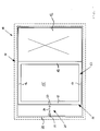
- FIG. 1 shown schematically and identified there by the reference numeral 10.
- the sliding door assembly 10 includes a frame 11 shown in dashed lines, which is fixed in place and building.
- the frame 11 preferably has a particular glazed fixed field 12, which is marked in the drawing with a diagonal cross.
- the frame 11 also serves to arrange a door leaf 13, which is displaceable between a closed position and an open position, in which the door leaf 13 overlaps the fixed field 12 in sections.
- the door leaf 13 is in particular a lifting / sliding door, which is not only horizontally displaceable, but can also be raised and lowered. In a lowered state of the door leaf 13 is a effective sealing of the door leaf 13 in the frame 11 simplified. In a raised state of the door leaf 13, this can be moved horizontally.
- the door leaf 13 has a sash 14 which limits a sash box 15.
- the wing panel 15 may be formed for example by a glazing.
- the casement 14 has an upper profile 16, a lower profile 17 and vertical profiles 18 and 19.
- the vertical profile 18 is in a closed state of the door leaf 13 on a vertical frame part 20 of the frame 11 at.
- This vertical profile 18 is understood in the context of the present invention as a "wing-side” profile.
- the frame part 20 is understood as a "frame-side” profile.
- a locking device 21 which has a locking bolt 22 and a cooperating with the locking bolt 22 - here only schematically illustrated - bolt receptacle 23 has.
- the bolt receptacle 23 is formed as a passage, recess or opening.
- the locking bolt 22 is adjustable in at least one adjustment direction of a plane, wherein the normal vector of the plane is defined by the direction of displacement 24 of the door leaf 13.
- a first adjustment direction is preferably in a plane whose normal vector is defined by the displacement direction 24 of the door leaf 13, and is oriented orthogonal to a plane formed by the frame 11.
- the first adjustment direction in the in Fig. 1 be shown vertically aligned representation.
- a second adjustment direction is preferably in a plane whose normal vector is defined by the displacement direction 24 of the door leaf 13, and is aligned orthogonal to the first adjustment direction.
- the second adjustment direction may be oriented orthogonal to the plane formed by the frame 11.
- the locking bolt 22 is additionally adjustable in the direction of displacement 24 of the door leaf 13.
- FIG. 2 shows a front view of a part of the locking device 21 according to a first embodiment.
- This part of the locking device 21 can also be referred to as an adjusting device 25.
- the adjusting device 25 has a locking bolt 22 which is mounted on a base plate 26 by means of fastening screws 27.
- the locking bolt 22 has as a mounting flange serving plate-like portions 28 which are provided with passages 29 in the form of elongated holes 30.
- the longitudinal axis of the slots 30 is oriented horizontally in the mounting position of the locking bolt 22.
- the base plate 26 has passages 31, which serve to receive - not shown here - fixing screws over which the base plate 26 and thus the entire adjuster 25 on the frame 11, in particular on the vertical frame member 20, can be fastened.
- the locking bolt 22 can be adjusted in its position, by loosening the fastening screws 27 and subsequent displacement of the locking bolt 22.
- the locking bolt 22 - based on the in FIG. 2 shown illustration - laterally or horizontally adjustable.
- the passages 29 and the passages 31 are countersunk. These countersinks are used to accommodate screw heads of the mounting screws, which in the case of countersunk screws, a flush or almost flush surface can be achieved.
- the locking bolt 22 is adjustable in a direction of the plane E, namely a first adjustment direction. In the present exemplary embodiment, this direction projects perpendicularly out of the plane of the drawing.
- the plane E is parallel to the base plate 26. In Fig. 3 the plane E projects vertically out of the plane of the drawing.
- FIG. 3 The individual elements in FIG. 3 are given the same reference numbers as in FIG. 2 provided so as to avoid repetition on the designs too FIG. 2 is referenced.
- FIG. 4 shows a front view of a part of the locking device 21 according to a second embodiment. This part of the locking device 21 may be referred to as adjusting means 25.
- the base plate 26 passages 31 in the form of slots 32.
- the longitudinal axis of the elongated holes 32 is oriented in the mounting position of the base plate 26 in the vertical direction.
- FIG. 5 shows a sectional view of the part of the locking device 21 according to FIG. 4 along an in FIG. 4 with VV designated cutting plane. Both the passages 29 and the passages 31 are countersunk for receiving fastening screws. The passages 31 are formed as slots 32.
- the locking bolt 22 is adjustable in two directions of the plane E, namely a first adjustment direction and a second adjustment direction.
- the plane E is parallel to the base plate 26. In Fig. 5 the plane E projects vertically out of the plane of the drawing.
- the first adjustment direction protrudes vertically out of the plane of the drawing.
- the second adjustment direction is oriented orthogonal to the first adjustment direction and lies in the plane E.
- FIG. 6 shows a front view of a part of the locking device 21 according to a third embodiment.
- This part of the locking device can be referred to as adjusting device 25.
- the base plate 26 is equipped according to the third embodiment with further passages 33, each having an internal thread. By means of adjusting screws 34 introduced into these passages, the distance between the frame 11 of the sliding door arrangement 10 and the base plate 26 can be adjusted.
- the locking bolt 22 can hereby be adjusted in the direction of displacement 24 of the door leaf 13.
- FIG. 7 shows a sectional view of the part of the locking device according to FIG. 6 along an in FIG. 6 with VII-VII designated cutting plane.
- FIG. 7 is the adjustability in the direction of the door leaf by means of screws 34 in the form of grub screws 35 clearly visible. By screwing the grub screws 35 protrude this - in the illustration according to FIG. 7 - To the left beyond the base plate 37 and thus reach in the assembled state with the frame 11, in particular with the vertical frame member 20 in contact.
- the adjusting screws 34 in the form of grub screws 35 have screw axes 36 which represent adjusting axes 37.
- the adjustment axes 37 are oriented parallel to the displacement direction 24 of the door leaf 13.
- the locking bolt 22 is adjustable in two directions of the plane E, namely a first adjustment direction and a second adjustment direction.
- the plane E is parallel to the base plate 26. In Fig. 7 the plane E projects vertically out of the plane of the drawing.
- the first adjustment direction protrudes vertically out of the plane of the drawing.
- the second adjustment direction is oriented orthogonal to the first adjustment direction and lies in the plane E.
- the base plate 26 is spaced from the frame 11, in particular from the vertical frame part 20, by the amount by which the adjusting screws 34 in the form of the grub screws 35 project beyond the base plate 26. This allows the closed position of the door leaf 13 relative to the frame 11, in particular with respect to the vertical frame part 20 set. For a complete seal between door leaf 13 and frame 11 thus the closing pressure can be specified.
Landscapes
- Hinges (AREA)
Abstract
Description
- Die Erfindung betrifft eine Schiebetüranordnung, umfassend einen ortsfesten Rahmen, einen horizontal verschiebbaren Türflügel und eine Verriegelungseinrichtung zum Arretieren des Türflügels am Rahmen, wobei die Verriegelungseinrichtung einen Riegelbolzen und eine mit dem Riegelbolzen zusammenwirkende Bolzenaufnahme aufweist.
- Eine Schiebetüranordnung der eingangs genannten Art ist aus der
DE 26 03 240 A1 bekannt. Bei Schiebetüranordnungen oder Kipp-Schiebetüranordnungen, die als Teil einer Gebäudeverglasung benutzt werden, kommen Verriegelungseinrichtungen zum Einsatz, die einen Riegelbolzen und eine mit dem Riegelbolzen zusammenwirkende Bolzenaufnahme aufweisen. Diese lassen sich in eine die Flügeltür verriegelnde Schließstellung und in eine die Flügeltür freigebende Freigabestellung bringen. Dabei ist problematisch, dass Riegelbolzen und Bolzenaufnahme nicht hinreichend in Flucht oder ausgerichtet zueinander stehen können, so dass diese beim Öffnen und/oder Schließen der Schiebetür unter erhöhtem Verschleiß aufeinander treffen, zumindest jedoch aneinander streifen, und sich erst dann "fluchten". Dies führt durch für den Anwender deutlich spürbares Ruckeln zu erheblichen Beeinträchtigungen in der Handhabung. Durch den erhöhten Verschleiß ist ein dauerhafter und zuverlässiger Betrieb nicht gewährleistet. Manuelle Nacharbeit durch spanende Bearbeitung, bspw. ein Abfeilen des Riegelbolzens, ist nicht reversibel und schwächt die bearbeiteten Elemente. - Der vorliegenden Erfindung liegt daher die Aufgabe zugrunde, eine Schiebetüranordnung der eingangs genannten Art derart auszugestalten und weiterzubilden, dass eine komfortable und dauerhaft zuverlässige Verwendung ermöglicht ist.
- Diese Aufgabe wird erfindungsgemäß dadurch gelöst, dass der Riegelbolzen in mindestens einer ersten Einstellrichtung einer Ebene einstellbar ist, wobei der Normalenvektor der Ebene durch die Verschieberichtung des Türflügels definiert ist.
- Erfindungsgemäß sind der Riegelbolzen und die mit dem Riegelbolzen zusammenwirkende Bolzenaufnahme der Verriegelungseinrichtung nicht nur an der Schiebetüranordnung montiert, sondern in ihrer Position relativ zueinander anpassbar. Hierzu ist der Riegelbolzen in mindestens einer ersten Richtung einer Ebene, nämlich einer ersten Einstellrichtung einer Ebene, einstellbar. Der Normalenvektor dieser Ebene ist durch die Verschieberichtung des Türflügels definiert.
- Die eine Einstellung des Riegelbolzens ermöglichende Mimik kann auch als Einstelleinrichtung bezeichnet werden. Hiermit lässt sich die Flucht zwischen Riegelbolzen und der - den Riegelbolzen zum Verschließen der Schiebetüranordnung aufnehmenden - Bolzenaufnahme auf einfache Weise einstellen. Somit ist eine reversible Justierung der Verriegelungseinrichtung möglich, und zwar über die gesamte Einsatzdauer der Schiebetüranordnung hinweg. Herstellungstoleranzen können ausgeglichen werden. Auf Grund der möglichen Einstellbarkeit des Riegelbolzens nach der Montage der Verriegelungseinrichtung ist deren Montage und damit die Montage der Schiebetüranordnung insgesamt deutlich vereinfacht. Eventuelle Montagefehler können auf einfache Weise korrigiert werden.
- In vorteilhafter Weise ist die erste Einstellrichtung des Riegelbolzens orthogonal zu einer durch den Rahmen gebildeten Ebene orientiert. Damit lassen sich Riegelbolzen und Bolzenaufnahme relativ zueinander "fluchten", und zwar in - in Verschieberichtung des Türflügels gesehen - seitlicher Richtung. Dadurch lassen sich Fehlausrichtungen, bspw. infolge von Montagefehlern, in seitlicher Richtung ausräumen. Auch der Einbauwinkel des Bolzen lässt sich korrigieren, jedenfalls in geringem Umfang.
- Alternativ hierzu ist es von Vorteil, wenn die erste Einstellrichtung des Riegelbolzens in einer durch den Rahmen gebildeten Ebene liegt und orthogonal zur Verschieberichtung des Türflügels orientiert ist. Auf diese Weise sind Korrekturen der Ausrichtung von Riegelbolzen und Bolzenaufnahme in - bezogen auf die Einbaulage des ortsfesten Rahmens - senkrechter Richtung möglich.
- Für eine möglichst stabile Anordnung des Riegelbolzens am Rahmen ist es von Vorteil, wenn der Riegelbolzen plattenartige Abschnitte mit Durchgängen in Form von Langlöchern aufweist und mittels in die Langlöcher eingebrachten Befestigungsschrauben verstellbar mit dem Rahmen verbunden ist. Damit kann eine Ausrichtung von Riegelbolzen und Bolzenaufnahme erfolgen, und zwar durch Verändern der Positionen des Riegelbolzens in der Einstellrichtung.
- Bevorzugt ist es, wenn die Längsrichtung der Langlöcher mit der Einstellrichtung übereinstimmt. Somit kann eine einfache Einstellung des Riegelbolzens erfolgen, nämlich durch Lösen der Befestigungsschrauben, Positionieren des Riegelbolzens und anschließendem Festziehen der Befestigungsschrauben. Eine einfache Handhabung der Einstellung ist realisiert.
- Für eine umfassende Einstellbarkeit ist es von Vorteil, wenn der Riegelbolzen in einer zweiten Einstellrichtung der Ebene einstellbar ist, deren Normalenvektor durch die Verschieberichtung des Türflügels definiert ist und dass die zweite Einstellrichtung orthogonal zur ersten Einstellrichtung ausgerichtet ist. Auf diese Weise ist die Einstellbarkeit des Riegelbolzens nicht auf ein Einstellen in einer Richtung beschränkt, sondern lässt sich eine Positionierung des Riegelbolzens in zwei Richtungen vornehmen. Damit ist der Riegelbolzen innerhalb eines Ebenenabschnitts einstellbar. Mit anderen Worten lässt sich der Riegelbolzen relativ zum Rahmen in seiner seitlichen Position und seiner Höhe einstellen. Montagefehler in - bezogen auf die Einbaulage des Riegelbolzens - seitlicher und vertikaler Richtung lassen sich korrigieren.
- Für eine besonders stabile Befestigung des Riegelbolzens mit konstruktiv einfachen Mitteln ist der Riegelbolzen mittels einer separat bereitgestellten Grundplatte mit Durchgängen und mittels in diese Durchgänge eingebrachten Befestigungsschrauben am Rahmen befestigt. Mit anderen Worten ist der Riegelbolzen selbst nicht unmittelbar am Rahmen befestigt, sondern mittels einer Grundplatte. Der Riegelbolzen wiederum ist über die Durchgänge in den plattenartigen Abschnitten an der Grundplatte befestigt. Bei einem Defekt des Riegelbolzens muss nur dieser, nicht jedoch die Verriegelungseinrichtung insgesamt ausgewechselt werden. Die Montage ist auf Grund der in zumindest einer Richtung, beispielsweise der zweiten Einstellrichtung, vorgegebenen Position des Riegelbolzens erheblich vereinfacht.
- Bevorzugt ist es, wenn die Durchgänge der Grundplatte als Langlöcher ausgebildet und derart ausgerichtet sind, dass die Grundplatte entlang der zweiten Einstellrichtung des Riegelbolzens verstellbar ist. Somit ist mit konstruktiv einfachen Mitteln eine Einstellmöglichkeit gegeben, wobei durch geringfügiges Lösen der Befestigungsschrauben der Grundplatte diese lediglich in einer Richtung verstellbar ist. Damit ist eine Einstellung mit einfacher Handhabung realisierbar.
- Vorzugsweise ist der Riegelbolzen zusätzlich in Verschieberichtung des Türflügels einstellbar. Damit lässt sich nicht nur eine Einstellung von Riegelbolzen und Bolzenaufnahme in seitlicher Position und/oder der Höhe vornehmen, sondern kann durch Einstellen des Riegelbolzens in Flügelverschieberichtung ein definiertes Schließen des Türflügels erfolgen. Somit kann mit einfachen konstruktiven Mitteln die Abdichtung zwischen Türflügel und Rahmen eingestellt werden.
- Für eine präzise Verstellbarkeit mit einfachen konstruktiven Mitteln ist es bevorzugt, wenn in der Grundplatte weitere Durchgänge ausgebildet sind, die ein Innengewinde aufweisen, und dass mittels in diese Durchgänge eingebrachten Stellschrauben der Abstand zwischen Rahmen und Grundplatte einstellbar ist. Hiermit ist eine einfache und platzsparende Stelleinrichtung verwirklicht. Bei den Stellschrauben kann es sich für eine besonders platzsparende Ausgestaltung um Madenschrauben handeln.
- Für ein möglichst ungehindertes Einstellen des Riegelbolzens ist es von Vorteil, wenn die plattenartigen Abschnitte des Riegelbolzens eine Baubreite aufweisen, welche mindestens um den Betrag des durch die Langlöcher des Riegelbolzens realisierten Einstellbereiches kleiner ist als eine Baubreite der Grundplatte. Auf diesem Wege ist ein ungehindertes Verstellen oder Einstellen des Riegelbolzens möglich, wobei die plattenartigen Abschnitte des Riegelbolzens auch in den jeweils maximal erreichbaren Einstellpositionen nicht über die Grundplatte hinausragen.
- Für eine besonders feine Einstellbarkeit des Riegelbolzens ist es von Vorteil, wenn der Riegelbolzen stufenlos einstellbar ist. Somit lässt sich der Riegelbolzen besonders genau positionieren und die Flucht zwischen Riegelbolzen und Bolzenaufnahme kann im Verstellbereich besonders genau eingestellt werden.
- Bevorzugt ist es, wenn der Riegelbolzen rahmenseitig und die Bolzenaufnahme flügelseitig angeordnet ist. Dabei ist denkbar, dass die Bolzenaufnahme einem - den Türflügel anhebenden und/oder verriegelnden - Getriebe zugeordnet ist. Im Wege einer konstruktiv einfachen Ausführung kann die Bolzenaufnahme als Ausnehmung oder Durchgang des Profilgestänges des Getriebes ausgebildet sein. Der Aufbau des Gestänges ist dadurch einfach gehalten. Durch die rahmenseitige Anordnung des Riegelbolzens ist dieser stabil am Rahmen angebunden. Auf Grund der feststehenden Position des Riegelbolzens ist die Einstellbarkeit erheblich vereinfacht.
- Es ist ebenfalls denkbar, dass der Riegelbolzen flügelseitig und die Bolzenaufnahme rahmenseitig angeordnet ist. In diesem Falle könnte die Bolzenaufnahme als Ausnehmung oder Durchgang ausgebildet sein, vorzugsweise am Rahmen selbst oder an einem am Rahmen befestigten Beschlag. Der Riegelbolzen könnte an einem Profil eines den Türflügel verriegelnden und/oder anhebenden Getriebes angeordnet sein.
- Weitere Merkmale und Vorteile der Erfindung sind Gegenstand der nachfolgenden Beschreibung und der zeichnerischen Darstellung bevorzugter Ausführungsbeispiele.
- In den Zeichnungen zeigen:
- Fig. 1
- eine schematische Darstellung einer Ausführungsform einer Schiebetüranordnung mit einer Verriegelungseinrichtung zum Arretieren des Türflügels am Rahmen;
- Fig. 2
- eine Vorderansicht eines Teils der Verriegelungseinrichtung gemäß einem ersten Ausführungsbeispiel;
- Fig. 3
- eine geschnittene Ansicht des Teils der Verriegelungseinrichtung gemäß
Fig. 2 entlang einer inFig. 2 mit III-III bezeichneten Schnittebene; - Fig. 4
- eine Vorderansicht eines Teils der Verriegelungseinrichtung gemäß einem zweiten Ausführungsbeispiel;
- Fig. 5
- eine geschnittene Ansicht des Teils der Verriegelungseinrichtung gemäß
Fig. 4 entlang einer inFig. 4 mit V-V bezeichneten Schnittebene; - Fig. 6
- eine Vorderansicht eines Teils der Verriegelungseinrichtung gemäß einem dritten Ausführungsbeispiel; und
- Fig. 7
- eine geschnittene Ansicht des Teils der Verriegelungseinrichtung gemäß
Fig. 6 entlang einer inFig. 6 mit VII-VII bezeichneten Schnittebene. - Eine Ausführungsform einer Schiebetüranordnung ist in
Figur 1 schematisch dargestellt und dort mit dem Bezugszeichen 10 gekennzeichnet. Die Schiebetüranordnung 10 umfasst einen mit gestrichelten Linien dargestellten Rahmen 11, welcher orts- und gebäudefest ist. Der Rahmen 11 weist vorzugsweise ein insbesondere verglastes Festfeld 12 auf, welches in der Zeichnung mit einem Diagonalkreuz markiert ist. - Der Rahmen 11 dient auch zur Anordnung eines Türflügels 13, der zwischen einer geschlossenen Stellung und einer geöffneten Stellung, in welcher der Türflügel 13 das Festfeld 12 abschnittsweise überlappt, verschiebbar ist.
- Bei dem Türflügel 13 handelt es sich insbesondere um eine Hebe-/Schiebetür, welche nicht nur horizontal verschiebbar ist, sondern auch angehoben und abgesenkt werden kann. In einem abgesenkten Zustand des Türflügels 13 ist eine wirksame Abdichtung des Türflügels 13 in dem Rahmen 11 vereinfacht. In einem angehobenen Zustand des Türflügels 13 kann dieser horizontal verschoben werden.
- Der Türflügel 13 weist einen Flügelrahmen 14 auf, der ein Flügelfeld 15 begrenzt. Das Flügelfeld 15 kann beispielsweise durch eine Verglasung gebildet sein. Der Flügelrahmen 14 weist ein oberes Profil 16, ein unteres Profil 17 sowie Vertikalprofile 18 und 19 auf.
- Das Vertikalprofil 18 liegt in einem geschlossenen Zustand des Türflügels 13 an einem vertikalen Rahmenteil 20 des Rahmens 11 an. Dieses Vertikalprofil 18 wird im Rahmen der vorliegenden Erfindung als "flügelseitiges" Profil verstanden. Das Rahmenteil 20 wird als "rahmenseitiges" Profil verstanden.
- In einem geschlossenen Zustand des Türflügels 13 können das Vertikalprofil 18 und das vertikale Rahmenteil 20 des Rahmens 11 miteinander verriegelt sein. Hierfür ist eine Verriegelungseinrichtung 21 vorgesehen, die einen Riegelbolzen 22 und eine mit dem Riegelbolzen 22 zusammenwirkende - hier lediglich schematisch dargestellte - Bolzenaufnahme 23 aufweist. Die Bolzenaufnahme 23 ist als Durchgang, Ausnehmung oder Öffnung ausgebildet. Der Riegelbolzen 22 ist in mindestens einer Einstellrichtung einer Ebene einstellbar, wobei der Normalenvektor der Ebene durch die Verschieberichtung 24 des Türflügels 13 definiert ist.
- Eine erste Einstellrichtung liegt vorzugsweise in einer Ebene, deren Normalenvektor durch die Verschieberichtung 24 des Türflügels 13 definiert ist, und ist orthogonal zu einer durch den Rahmen 11 gebildeten Ebene orientiert. Mit anderen Worten kann die erste Einstellrichtung in der in
Fig. 1 gezeigten Darstellung senkrecht ausgerichtet sein. - Eine zweite Einstellrichtung liegt vorzugsweise in einer Ebene, deren Normalenvektor durch die Verschieberichtung 24 des Türflügels 13 definiert ist, und ist orthogonal zur ersten Einstellrichtung ausgerichtet. Mit anderen Worten kann die zweite Einstellrichtung orthogonal zur durch den Rahmen 11 gebildeten Ebene orientiert sein.
- Vorzugsweise ist der Riegelbolzen 22 zusätzlich in Verschieberichtung 24 des Türflügels 13 einstellbar.
-
Figur 2 zeigt eine Vorderansicht eines Teils der Verriegelungseinrichtung 21 gemäß einem ersten Ausführungsbeispiel. Dieser Teil der Verriegelungseinrichtung 21 kann auch als Einstelleinrichtung 25 bezeichnet werden. Die Einstelleinrichtung 25 weist einen Riegelbolzen 22 auf, der an einer Grundplatte 26 mittels Befestigungsschrauben 27 montiert ist. - Der Riegelbolzen 22 weist als Befestigungsflansch dienende plattenartige Abschnitte 28 auf, die mit Durchgängen 29 in Form von Langlöchern 30 versehen sind. Die Längsachse der Langlöcher 30 ist in Montageposition des Riegelbolzens 22 horizontal orientiert. Die Grundplatte 26 weist Durchgänge 31 auf, die zur Aufnahme von - hier nicht dargestellten - Befestigungsschrauben dienen, über die die Grundplatte 26 und damit die gesamte Einstelleinrichtung 25 am Rahmen 11, insbesondere am vertikalen Rahmenteil 20, befestigbar ist.
- Mittels der Einstelleinrichtung 25 kann der Riegelbolzen 22 in seiner Position eingestellt werden, und zwar durch Lösen der Befestigungsschrauben 27 und anschließendes Verschieben des Riegelbolzens 22. Somit ist der Riegelbolzen 22 - bezogen auf die in
Figur 2 gezeigte Darstellung - seitlich oder horizontal einstellbar. - In
Figur 3 ist erkennbar, dass die Durchgänge 29 sowie die Durchgänge 31 angesenkt sind. Diese Ansenkungen dienen zur Aufnahme von Schraubenköpfen der Befestigungsschrauben, wobei im Falle von Senkkopfschrauben eine bündige oder nahezu bündige Oberfläche erreicht werden kann. Der Riegelbolzen 22 ist in einer Richtung der Ebene E, nämlich einer ersten Einstellrichtung, einstellbar. Diese Richtung ragt im vorliegenden Ausführungsbeispiel senkrecht aus der Zeichenebene hinaus. Die Ebene E ist parallel zur Grundplatte 26. InFig. 3 ragt die Ebene E senkrecht aus der Zeichenebene hinaus. - Die einzelnen Elemente in
Figur 3 sind mit den gleichen Bezugszeichen wie inFigur 2 versehen, so dass zur Vermeidung von Wiederholungen auf die Ausführungen zuFigur 2 verwiesen wird. -
Figur 4 zeigt eine Vorderansicht eines Teils der Verriegelungseinrichtung 21 gemäß einem zweiten Ausführungsbeispiel. Dieser Teil der Verriegelungseinrichtung 21 kann als Einstelleinrichtung 25 bezeichnet werden. - Im Unterschied zum voranstehenden Ausführungsbeispiel weist die Grundplatte 26 Durchgänge 31 in Form von Langlöchern 32 auf. Die Längsachse der Langlöcher 32 ist in Montageposition der Grundplatte 26 in vertikaler Richtung orientiert. Somit kann über ein Lösen der - hier nicht dargestellten - Befestigungsschrauben, mit denen die Grundplatte 26 am Rahmen 11, insbesondere am vertikalen Rahmenteil 20, befestigt ist, ein Einstellen in vertikaler Richtung erfolgen. Ein Einstellen in der
Figur 4 dargestellten horizontalen Richtung erfolgt durch ein Lösen der Befestigungsschrauben 27, wonach der Riegelbolzen 22 entlang der als Langlöcher 30 ausgebildeten Durchgänge 29 verschoben werden kann. Somit ist im vorliegenden Ausführungsbeispiel ein Einstellen des Riegelbolzens 22 in zwei Richtungen und damit innerhalb einer Ebene oder eines Ebenenabschnitts ermöglicht. - Gleiche oder funktional gleiche Elemente sind in der vorliegenden Figur mit gleichen Bezugszeichen wie im ersten Ausführungsbeispiel versehen, so dass zur Vermeidung von Wiederholungen auf die Ausführungen zu
Figur 2 verwiesen wird. -
Figur 5 zeigt eine geschnittene Ansicht des Teils der Verriegelungseinrichtung 21 gemäßFigur 4 entlang einer inFigur 4 mit V-V bezeichneten Schnittebene. Sowohl die Durchgänge 29 als auch die Durchgänge 31 sind zur Aufnahme von Befestigungsschrauben angesenkt. Die Durchgänge 31 sind als Langlöcher 32 ausgebildet. - Der Riegelbolzen 22 ist in zwei Richtungen der Ebene E, nämlich einer ersten Einstellrichtung und einer zweiten Einstellrichtung, einstellbar. Die Ebene E ist parallel zur Grundplatte 26. In
Fig. 5 ragt die Ebene E senkrecht aus der Zeichenebene hinaus. Die erste Einstellrichtung ragt senkrecht aus der Zeichenebene hinaus. Die zweite Einstellrichtung ist orthogonal zur ersten Einstellrichtung orientiert und liegt in der Ebene E. - Zur Vermeidung von Wiederholungen sei hier auf die Ausführungen zu
Figur 2 verwiesen, wobei gleiche Elemente mit gleichen Bezugszeichen versehen sind. -
Figur 6 zeigt eine Vorderansicht eines Teils der Verriegelungseinrichtung 21 gemäß einem dritten Ausführungsbeispiel. Dieser Teil der Verriegelungseinrichtung kann als Einstelleinrichtung 25 bezeichnet werden. Im Unterschied zum voranstehend beschriebenen zweiten Ausführungsbeispiel ist die Grundplatte 26 gemäß dem dritten Ausführungsbeispiel mit weiteren Durchgängen 33 ausgestattet, die jeweils ein Innengewinde aufweisen. Mittels in diese Durchgänge eingebrachten Stellschrauben 34 ist der Abstand zwischen dem Rahmen 11 der Schiebetüranordnung 10 und der Grundplatte 26 einstellbar. Der Riegelbolzen 22 lässt sich hiermit in Verschieberichtung 24 des Türflügels 13 einstellen. - Die gegenüber den voranstehend beschriebenen Ausführungsbeispielen gleichen oder funktional gleichen Elemente sind in der vorliegenden Figur mit gleichen Bezugszeichen versehen, so dass zur Vermeidung von Wiederholungen auf die Ausführungen zu den voranstehend beschriebenen Ausführungsbeispielen verwiesen wird.
-
Figur 7 zeigt eine geschnittene Ansicht des Teils der Verriegelungseinrichtung gemäßFigur 6 entlang einer inFigur 6 mit VII-VII bezeichneten Schnittebene. InFigur 7 ist die Einstellbarkeit in Verschieberichtung des Türflügels mittels der Stellschrauben 34 in Form von Madenschrauben 35 deutlich zu erkennen. Durch Eindrehen der Madenschrauben 35 ragen diese - in der Darstellung gemäßFigur 7 - nach links über die Grundplatte 37 hinaus und gelangen somit im montierten Zustand mit dem Rahmen 11, insbesondere mit dem vertikalen Rahmenteil 20, in Kontakt. - Die Stellschrauben 34 in Form der Madenschrauben 35 weisen Schraubenachsen 36 auf, die Einstellachsen 37 darstellen. Die Einstellachsen 37 sind parallel zur Verschieberichtung 24 des Türflügels 13 orientiert.
- Der Riegelbolzen 22 ist in zwei Richtungen der Ebene E, nämlich einer ersten Einstellrichtung und einer zweiten Einstellrichtung, einstellbar. Die Ebene E ist parallel zur Grundplatte 26. In
Fig. 7 ragt die Ebene E senkrecht aus der Zeichenebene hinaus. Die erste Einstellrichtung ragt senkrecht aus der Zeichenebene hinaus. Die zweite Einstellrichtung ist orthogonal zur ersten Einstellrichtung orientiert und liegt in der Ebene E. - Die Grundplatte 26 ist vom Rahmen 11, insbesondere vom vertikalen Rahmenteil 20, beabstandet, und zwar um den Betrag, um den die Stellschrauben 34 in Form der Madenschrauben 35 über die Grundplatte 26 hinausragen. Hiermit lässt sich die Schließposition des Türflügels 13 gegenüber dem Rahmen 11, insbesondere gegenüber dem vertikalen Rahmenteil 20, einstellen. Für eine vollständige Abdichtung zwischen Türflügel 13 und Rahmen 11 kann somit der Schließdruck vorgegeben werden.
Claims (13)
- Schiebetüranordnung (10), umfassend einen ortsfesten Rahmen (11), einen horizontal verschiebbaren Türflügel (13) und eine Verriegelungseinrichtung (21) zum Arretieren des Türflügels (13) am Rahmen (11), wobei die Verriegelungseinrichtung (21) einen Riegelbolzen (22) und eine mit dem Riegelbolzen (22) zusammenwirkende Bolzenaufnahme (23) aufweist, dadurch gekennzeichnet, dass der Riegelbolzen (22) in mindestens einer ersten Einstellrichtung einer Ebene (E) einstellbar ist, wobei der Normalenvektor der Ebene (E) durch die Verschieberichtung (24) des Türflügels (13) definiert ist.
- Schiebetüranordnung (10) nach Anspruch 1, dadurch gekennzeichnet, dass die erste Einstellrichtung des Riegelbolzens (22) orthogonal zu einer durch den Rahmen (11) gebildeten Ebene orientiert ist.
- Schiebetüranordnung (10) nach Anspruch 1, dadurch gekennzeichnet, dass die erste Einstellrichtung des Riegelbolzens (22) in einer durch den Rahmen (11) gebildeten Ebene liegt und orthogonal zur Verschieberichtung (24) des Türflügels (13) orientiert ist.
- Schiebetüranordnung (10) nach einem der voranstehenden Ansprüche, dadurch gekennzeichnet, dass der Riegelbolzen (22) plattenartige Abschnitte (28) mit Durchgängen (29) in Form von Langlöchern (30) aufweist und mittels in die Langlöcher (30) eingebrachten Befestigungsschrauben (27) verstellbar mit dem Rahmen (11) verbunden ist.
- Schiebetüranordnung (10) nach Anspruch 4, dadurch gekennzeichnet, dass die Längsrichtung der Langlöcher (30) mit der Einstellrichtung übereinstimmt.
- Schiebetüranordnung (10) nach einem der voranstehenden Ansprüche, dadurch gekennzeichnet, dass der Riegelbolzen (22) in einer zweiten Einstellrichtung der Ebene (E) einstellbar ist, deren Normalenvektor durch die Verschieberichtung (24) des Türflügels (13) definiert ist, und dass die zweite Einstellrichtung orthogonal zur ersten Einstellrichtung ausgerichtet ist.
- Schiebetüranordnung (10) nach einem der voranstehenden Ansprüche, dadurch gekennzeichnet, dass der Riegelbolzen (22) mittels einer separat bereitgestellten Grundplatte (26) mit Durchgängen (31) und mittels in diese Durchgänge (31) eingebrachten Befestigungsschrauben am Rahmen (11) befestigt ist.
- Schiebetüranordnung (10) nach Anspruch 7, dadurch gekennzeichnet, dass die Durchgänge (31) der Grundplatte (26) als Langlöcher (32) ausgebildet und derart ausgerichtet sind, dass die Grundplatte (26) entlang einer zweiten Einstellrichtung des Riegelbolzens (22) verstellbar ist.
- Schiebetüranordnung (10) nach einem der voranstehenden Ansprüche, dadurch gekennzeichnet, dass der Riegelbolzen (22) zusätzlich in Verschieberichtung (24) des Türflügels (13) einstellbar ist.
- Schiebetüranordnung (10) einem der Ansprüche 7 bis 9, dadurch gekennzeichnet, dass in der Grundplatte (26) weitere Durchgänge (33) ausgebildet sind, die ein Innengewinde aufweisen, und dass mittels in diese Durchgänge (33) eingebrachten Stellschrauben (34, 35) der Abstand zwischen Rahmen (11) und Grundplatte (26) einstellbar ist.
- Schiebetüranordnung (10) nach einem der Ansprüche 4 bis 10, dadurch gekennzeichnet, dass die plattenartigen Abschnitte (28) des Riegelbolzens (22) eine Baubreite aufweisen, die mindestens um den Betrag des durch die Langlöcher (30) des Riegelbolzens (22) realisierten Einstellbereichs kleiner ist als eine Baubreite der Grundplatte (26).
- Schiebetüranordnung (10) nach einem der voranstehenden Ansprüche, dadurch gekennzeichnet, dass der Riegelbolzen (22) stufenlos einstellbar ist.
- Schiebetüranordnung (10) nach einem der voranstehenden Ansprüche, dadurch gekennzeichnet, dass der Riegelbolzen (22) rahmenseitig und die Bolzenaufnahme (23) flügelseitig angeordnet ist.
Priority Applications (3)
| Application Number | Priority Date | Filing Date | Title |
|---|---|---|---|
| PL14168883T PL2947242T3 (pl) | 2014-05-19 | 2014-05-19 | Zespół drzwi przesuwnych |
| ES14168883.8T ES2687253T3 (es) | 2014-05-19 | 2014-05-19 | Disposición de puerta corrediza |
| EP14168883.8A EP2947242B1 (de) | 2014-05-19 | 2014-05-19 | Schiebetüranordnung |
Applications Claiming Priority (1)
| Application Number | Priority Date | Filing Date | Title |
|---|---|---|---|
| EP14168883.8A EP2947242B1 (de) | 2014-05-19 | 2014-05-19 | Schiebetüranordnung |
Publications (2)
| Publication Number | Publication Date |
|---|---|
| EP2947242A1 true EP2947242A1 (de) | 2015-11-25 |
| EP2947242B1 EP2947242B1 (de) | 2018-07-11 |
Family
ID=50732009
Family Applications (1)
| Application Number | Title | Priority Date | Filing Date |
|---|---|---|---|
| EP14168883.8A Not-in-force EP2947242B1 (de) | 2014-05-19 | 2014-05-19 | Schiebetüranordnung |
Country Status (3)
| Country | Link |
|---|---|
| EP (1) | EP2947242B1 (de) |
| ES (1) | ES2687253T3 (de) |
| PL (1) | PL2947242T3 (de) |
Citations (5)
| Publication number | Priority date | Publication date | Assignee | Title |
|---|---|---|---|---|
| DE2603240A1 (de) | 1976-01-29 | 1977-10-06 | Siegenia Frank Kg | Beschlag zum betaetigen und/oder bewegen eines kipp-schiebefluegels von fenstern, tueren o.dgl. |
| FR2715183A1 (fr) * | 1994-01-14 | 1995-07-21 | Automatismes Production Eurl | Serrure électromécanique autonome de haute sécurité à lecteur de clé à puce pour système de contrôle et de gestion d'accès. |
| DE19522220A1 (de) * | 1995-06-20 | 1997-01-02 | Opel Adam Ag | Schließvorrichtung |
| US5775749A (en) * | 1996-08-08 | 1998-07-07 | Andersen Corporation | Latch keeper assembly |
| DE202008004173U1 (de) * | 2008-03-26 | 2009-08-06 | Hoppe Ag, St. Martin | Verriegelungsvorrichtung |
-
2014
- 2014-05-19 EP EP14168883.8A patent/EP2947242B1/de not_active Not-in-force
- 2014-05-19 PL PL14168883T patent/PL2947242T3/pl unknown
- 2014-05-19 ES ES14168883.8T patent/ES2687253T3/es active Active
Patent Citations (5)
| Publication number | Priority date | Publication date | Assignee | Title |
|---|---|---|---|---|
| DE2603240A1 (de) | 1976-01-29 | 1977-10-06 | Siegenia Frank Kg | Beschlag zum betaetigen und/oder bewegen eines kipp-schiebefluegels von fenstern, tueren o.dgl. |
| FR2715183A1 (fr) * | 1994-01-14 | 1995-07-21 | Automatismes Production Eurl | Serrure électromécanique autonome de haute sécurité à lecteur de clé à puce pour système de contrôle et de gestion d'accès. |
| DE19522220A1 (de) * | 1995-06-20 | 1997-01-02 | Opel Adam Ag | Schließvorrichtung |
| US5775749A (en) * | 1996-08-08 | 1998-07-07 | Andersen Corporation | Latch keeper assembly |
| DE202008004173U1 (de) * | 2008-03-26 | 2009-08-06 | Hoppe Ag, St. Martin | Verriegelungsvorrichtung |
Also Published As
| Publication number | Publication date |
|---|---|
| EP2947242B1 (de) | 2018-07-11 |
| ES2687253T3 (es) | 2018-10-24 |
| PL2947242T3 (pl) | 2018-12-31 |
Similar Documents
| Publication | Publication Date | Title |
|---|---|---|
| EP2851497B1 (de) | Justierbare Montagevorrichtung für ein Schiebeelement sowie Schiebevorrichtung | |
| EP3102759B1 (de) | Beschlag eines zumindest hebbaren und verschiebbaren flügels von fenstern oder türen | |
| EP3786405B1 (de) | Möbelantrieb zum bewegen eines bewegbar gelagerten möbelteiles | |
| EP2947242B1 (de) | Schiebetüranordnung | |
| DE102021115490B4 (de) | Feststellvorrichtung für beidseitig angeschlagene Tür | |
| EP4146888B1 (de) | Scharnierbaugruppe mit gemeinsamer betätigung | |
| DE102013200305B4 (de) | Trennwand | |
| DE102012218887B4 (de) | Schließstück für ein Fenster, eine Tür oder dergleichen | |
| EP3029227A1 (de) | Beschlag mit einstellbarem Einspannbereich | |
| EP3101207B1 (de) | Schiebetüranordnung | |
| EP3243989B1 (de) | Beschlaganordnung | |
| EP3327228B1 (de) | Verriegelungsvorrichtung zum verriegeln und mitnehmen von mindestens zwei entlang einer ersten verschieberichtung und einer entgegengesetzten zweiten verschieberichtung verschiebbar gelagerten plattenförmigen elementen sowie wandandordnung mit mindestens zwei plattenförmigen elementen | |
| DE102013226720B4 (de) | Einstellbare Vertikalaussteifung mit Gleiter für einen abstellbaren Flügel eines Fensters einer Tür oder dergleichen | |
| EP2952657B1 (de) | Schiebetüranordnung | |
| DE102020112148B3 (de) | Scharnierverschluss | |
| EP4159964B1 (de) | Verriegelungsbeschlag für hebe-schiebetüre | |
| DE102022124497A1 (de) | Adapterteil zum selektiven verbinden unterschiedlicher koppelstangen mit einem laufwagen eines hebe-schiebeelements | |
| EP3029234B1 (de) | Einstellbarer Eckbeschlag | |
| DE102012111858B4 (de) | Verfahren zur Montage von Beschlagelementen | |
| EP3714121A1 (de) | Lehrenanordnung zur montage eines steuerelements eines schiebefensters oder einer schiebetür | |
| DE202017100721U1 (de) | Vorsatztür oder -fenster, insbesondere Insektenschutztür oder -fenster | |
| EP4621174A1 (de) | Riegelvorrichtung und tür- oder fensteranordnung | |
| EP4647573A1 (de) | Einzugsvorrichtung und tür- oder fensteranordnung | |
| DE102022114161A1 (de) | Zusatzverriegelungseinrichtung für eine Gebäudeverschlusseinrichtung, Verfahren zum Montieren einer solchen Zusatzverriegelungseinrichtung sowie entsprechende Gebäudeverschlusseinrichtung | |
| DE102022117895A1 (de) | Beschlaganordnung zum verriegeln eines verschiebbaren flügels |
Legal Events
| Date | Code | Title | Description |
|---|---|---|---|
| PUAI | Public reference made under article 153(3) epc to a published international application that has entered the european phase |
Free format text: ORIGINAL CODE: 0009012 |
|
| 17P | Request for examination filed |
Effective date: 20150602 |
|
| AK | Designated contracting states |
Kind code of ref document: A1 Designated state(s): AL AT BE BG CH CY CZ DE DK EE ES FI FR GB GR HR HU IE IS IT LI LT LU LV MC MK MT NL NO PL PT RO RS SE SI SK SM TR |
|
| AX | Request for extension of the european patent |
Extension state: BA ME |
|
| GRAP | Despatch of communication of intention to grant a patent |
Free format text: ORIGINAL CODE: EPIDOSNIGR1 |
|
| STAA | Information on the status of an ep patent application or granted ep patent |
Free format text: STATUS: GRANT OF PATENT IS INTENDED |
|
| RIC1 | Information provided on ipc code assigned before grant |
Ipc: E05B 15/02 20060101ALI20180126BHEP Ipc: E05B 17/20 20060101ALN20180126BHEP Ipc: E05B 65/08 20060101AFI20180126BHEP |
|
| INTG | Intention to grant announced |
Effective date: 20180213 |
|
| GRAS | Grant fee paid |
Free format text: ORIGINAL CODE: EPIDOSNIGR3 |
|
| GRAA | (expected) grant |
Free format text: ORIGINAL CODE: 0009210 |
|
| STAA | Information on the status of an ep patent application or granted ep patent |
Free format text: STATUS: THE PATENT HAS BEEN GRANTED |
|
| AK | Designated contracting states |
Kind code of ref document: B1 Designated state(s): AL AT BE BG CH CY CZ DE DK EE ES FI FR GB GR HR HU IE IS IT LI LT LU LV MC MK MT NL NO PL PT RO RS SE SI SK SM TR |
|
| REG | Reference to a national code |
Ref country code: GB Ref legal event code: FG4D Free format text: NOT ENGLISH |
|
| REG | Reference to a national code |
Ref country code: CH Ref legal event code: EP |
|
| REG | Reference to a national code |
Ref country code: AT Ref legal event code: REF Ref document number: 1017046 Country of ref document: AT Kind code of ref document: T Effective date: 20180715 |
|
| REG | Reference to a national code |
Ref country code: CH Ref legal event code: NV Representative=s name: DREISS PATENTANWAELTE PARTG MBB, DE |
|
| REG | Reference to a national code |
Ref country code: IE Ref legal event code: FG4D Free format text: LANGUAGE OF EP DOCUMENT: GERMAN |
|
| REG | Reference to a national code |
Ref country code: DE Ref legal event code: R096 Ref document number: 502014008782 Country of ref document: DE |
|
| REG | Reference to a national code |
Ref country code: ES Ref legal event code: FG2A Ref document number: 2687253 Country of ref document: ES Kind code of ref document: T3 Effective date: 20181024 |
|
| REG | Reference to a national code |
Ref country code: NL Ref legal event code: MP Effective date: 20180711 |
|
| REG | Reference to a national code |
Ref country code: LT Ref legal event code: MG4D |
|
| PG25 | Lapsed in a contracting state [announced via postgrant information from national office to epo] |
Ref country code: NL Free format text: LAPSE BECAUSE OF FAILURE TO SUBMIT A TRANSLATION OF THE DESCRIPTION OR TO PAY THE FEE WITHIN THE PRESCRIBED TIME-LIMIT Effective date: 20180711 |
|
| PG25 | Lapsed in a contracting state [announced via postgrant information from national office to epo] |
Ref country code: IS Free format text: LAPSE BECAUSE OF FAILURE TO SUBMIT A TRANSLATION OF THE DESCRIPTION OR TO PAY THE FEE WITHIN THE PRESCRIBED TIME-LIMIT Effective date: 20181111 Ref country code: RS Free format text: LAPSE BECAUSE OF FAILURE TO SUBMIT A TRANSLATION OF THE DESCRIPTION OR TO PAY THE FEE WITHIN THE PRESCRIBED TIME-LIMIT Effective date: 20180711 Ref country code: SE Free format text: LAPSE BECAUSE OF FAILURE TO SUBMIT A TRANSLATION OF THE DESCRIPTION OR TO PAY THE FEE WITHIN THE PRESCRIBED TIME-LIMIT Effective date: 20180711 Ref country code: BG Free format text: LAPSE BECAUSE OF FAILURE TO SUBMIT A TRANSLATION OF THE DESCRIPTION OR TO PAY THE FEE WITHIN THE PRESCRIBED TIME-LIMIT Effective date: 20181011 Ref country code: LT Free format text: LAPSE BECAUSE OF FAILURE TO SUBMIT A TRANSLATION OF THE DESCRIPTION OR TO PAY THE FEE WITHIN THE PRESCRIBED TIME-LIMIT Effective date: 20180711 Ref country code: FI Free format text: LAPSE BECAUSE OF FAILURE TO SUBMIT A TRANSLATION OF THE DESCRIPTION OR TO PAY THE FEE WITHIN THE PRESCRIBED TIME-LIMIT Effective date: 20180711 Ref country code: NO Free format text: LAPSE BECAUSE OF FAILURE TO SUBMIT A TRANSLATION OF THE DESCRIPTION OR TO PAY THE FEE WITHIN THE PRESCRIBED TIME-LIMIT Effective date: 20181011 Ref country code: GR Free format text: LAPSE BECAUSE OF FAILURE TO SUBMIT A TRANSLATION OF THE DESCRIPTION OR TO PAY THE FEE WITHIN THE PRESCRIBED TIME-LIMIT Effective date: 20181012 |
|
| PG25 | Lapsed in a contracting state [announced via postgrant information from national office to epo] |
Ref country code: HR Free format text: LAPSE BECAUSE OF FAILURE TO SUBMIT A TRANSLATION OF THE DESCRIPTION OR TO PAY THE FEE WITHIN THE PRESCRIBED TIME-LIMIT Effective date: 20180711 Ref country code: LV Free format text: LAPSE BECAUSE OF FAILURE TO SUBMIT A TRANSLATION OF THE DESCRIPTION OR TO PAY THE FEE WITHIN THE PRESCRIBED TIME-LIMIT Effective date: 20180711 Ref country code: AL Free format text: LAPSE BECAUSE OF FAILURE TO SUBMIT A TRANSLATION OF THE DESCRIPTION OR TO PAY THE FEE WITHIN THE PRESCRIBED TIME-LIMIT Effective date: 20180711 |
|
| REG | Reference to a national code |
Ref country code: DE Ref legal event code: R097 Ref document number: 502014008782 Country of ref document: DE |
|
| PG25 | Lapsed in a contracting state [announced via postgrant information from national office to epo] |
Ref country code: RO Free format text: LAPSE BECAUSE OF FAILURE TO SUBMIT A TRANSLATION OF THE DESCRIPTION OR TO PAY THE FEE WITHIN THE PRESCRIBED TIME-LIMIT Effective date: 20180711 Ref country code: CZ Free format text: LAPSE BECAUSE OF FAILURE TO SUBMIT A TRANSLATION OF THE DESCRIPTION OR TO PAY THE FEE WITHIN THE PRESCRIBED TIME-LIMIT Effective date: 20180711 Ref country code: EE Free format text: LAPSE BECAUSE OF FAILURE TO SUBMIT A TRANSLATION OF THE DESCRIPTION OR TO PAY THE FEE WITHIN THE PRESCRIBED TIME-LIMIT Effective date: 20180711 |
|
| PLBE | No opposition filed within time limit |
Free format text: ORIGINAL CODE: 0009261 |
|
| STAA | Information on the status of an ep patent application or granted ep patent |
Free format text: STATUS: NO OPPOSITION FILED WITHIN TIME LIMIT |
|
| PG25 | Lapsed in a contracting state [announced via postgrant information from national office to epo] |
Ref country code: SM Free format text: LAPSE BECAUSE OF FAILURE TO SUBMIT A TRANSLATION OF THE DESCRIPTION OR TO PAY THE FEE WITHIN THE PRESCRIBED TIME-LIMIT Effective date: 20180711 Ref country code: DK Free format text: LAPSE BECAUSE OF FAILURE TO SUBMIT A TRANSLATION OF THE DESCRIPTION OR TO PAY THE FEE WITHIN THE PRESCRIBED TIME-LIMIT Effective date: 20180711 Ref country code: SK Free format text: LAPSE BECAUSE OF FAILURE TO SUBMIT A TRANSLATION OF THE DESCRIPTION OR TO PAY THE FEE WITHIN THE PRESCRIBED TIME-LIMIT Effective date: 20180711 |
|
| 26N | No opposition filed |
Effective date: 20190412 |
|
| REG | Reference to a national code |
Ref country code: DE Ref legal event code: R082 Ref document number: 502014008782 Country of ref document: DE |
|
| PG25 | Lapsed in a contracting state [announced via postgrant information from national office to epo] |
Ref country code: SI Free format text: LAPSE BECAUSE OF FAILURE TO SUBMIT A TRANSLATION OF THE DESCRIPTION OR TO PAY THE FEE WITHIN THE PRESCRIBED TIME-LIMIT Effective date: 20180711 |
|
| GBPC | Gb: european patent ceased through non-payment of renewal fee |
Effective date: 20190519 |
|
| PG25 | Lapsed in a contracting state [announced via postgrant information from national office to epo] |
Ref country code: MC Free format text: LAPSE BECAUSE OF FAILURE TO SUBMIT A TRANSLATION OF THE DESCRIPTION OR TO PAY THE FEE WITHIN THE PRESCRIBED TIME-LIMIT Effective date: 20180711 |
|
| REG | Reference to a national code |
Ref country code: BE Ref legal event code: MM Effective date: 20190531 |
|
| PG25 | Lapsed in a contracting state [announced via postgrant information from national office to epo] |
Ref country code: LU Free format text: LAPSE BECAUSE OF NON-PAYMENT OF DUE FEES Effective date: 20190519 |
|
| PG25 | Lapsed in a contracting state [announced via postgrant information from national office to epo] |
Ref country code: TR Free format text: LAPSE BECAUSE OF FAILURE TO SUBMIT A TRANSLATION OF THE DESCRIPTION OR TO PAY THE FEE WITHIN THE PRESCRIBED TIME-LIMIT Effective date: 20180711 |
|
| PG25 | Lapsed in a contracting state [announced via postgrant information from national office to epo] |
Ref country code: GB Free format text: LAPSE BECAUSE OF NON-PAYMENT OF DUE FEES Effective date: 20190519 Ref country code: IE Free format text: LAPSE BECAUSE OF NON-PAYMENT OF DUE FEES Effective date: 20190519 |
|
| PG25 | Lapsed in a contracting state [announced via postgrant information from national office to epo] |
Ref country code: BE Free format text: LAPSE BECAUSE OF NON-PAYMENT OF DUE FEES Effective date: 20190531 |
|
| PG25 | Lapsed in a contracting state [announced via postgrant information from national office to epo] |
Ref country code: PT Free format text: LAPSE BECAUSE OF FAILURE TO SUBMIT A TRANSLATION OF THE DESCRIPTION OR TO PAY THE FEE WITHIN THE PRESCRIBED TIME-LIMIT Effective date: 20181111 Ref country code: FR Free format text: LAPSE BECAUSE OF NON-PAYMENT OF DUE FEES Effective date: 20190531 |
|
| PGFP | Annual fee paid to national office [announced via postgrant information from national office to epo] |
Ref country code: CH Payment date: 20200520 Year of fee payment: 7 Ref country code: DE Payment date: 20200520 Year of fee payment: 7 |
|
| PGFP | Annual fee paid to national office [announced via postgrant information from national office to epo] |
Ref country code: PL Payment date: 20200429 Year of fee payment: 7 Ref country code: IT Payment date: 20200528 Year of fee payment: 7 |
|
| PGFP | Annual fee paid to national office [announced via postgrant information from national office to epo] |
Ref country code: AT Payment date: 20200522 Year of fee payment: 7 |
|
| PGFP | Annual fee paid to national office [announced via postgrant information from national office to epo] |
Ref country code: ES Payment date: 20200728 Year of fee payment: 7 |
|
| PG25 | Lapsed in a contracting state [announced via postgrant information from national office to epo] |
Ref country code: CY Free format text: LAPSE BECAUSE OF FAILURE TO SUBMIT A TRANSLATION OF THE DESCRIPTION OR TO PAY THE FEE WITHIN THE PRESCRIBED TIME-LIMIT Effective date: 20180711 |
|
| PG25 | Lapsed in a contracting state [announced via postgrant information from national office to epo] |
Ref country code: MT Free format text: LAPSE BECAUSE OF FAILURE TO SUBMIT A TRANSLATION OF THE DESCRIPTION OR TO PAY THE FEE WITHIN THE PRESCRIBED TIME-LIMIT Effective date: 20180711 Ref country code: HU Free format text: LAPSE BECAUSE OF FAILURE TO SUBMIT A TRANSLATION OF THE DESCRIPTION OR TO PAY THE FEE WITHIN THE PRESCRIBED TIME-LIMIT; INVALID AB INITIO Effective date: 20140519 |
|
| REG | Reference to a national code |
Ref country code: DE Ref legal event code: R119 Ref document number: 502014008782 Country of ref document: DE |
|
| REG | Reference to a national code |
Ref country code: CH Ref legal event code: PL |
|
| REG | Reference to a national code |
Ref country code: AT Ref legal event code: MM01 Ref document number: 1017046 Country of ref document: AT Kind code of ref document: T Effective date: 20210519 |
|
| PG25 | Lapsed in a contracting state [announced via postgrant information from national office to epo] |
Ref country code: CH Free format text: LAPSE BECAUSE OF NON-PAYMENT OF DUE FEES Effective date: 20210531 Ref country code: AT Free format text: LAPSE BECAUSE OF NON-PAYMENT OF DUE FEES Effective date: 20210519 Ref country code: LI Free format text: LAPSE BECAUSE OF NON-PAYMENT OF DUE FEES Effective date: 20210531 |
|
| PG25 | Lapsed in a contracting state [announced via postgrant information from national office to epo] |
Ref country code: DE Free format text: LAPSE BECAUSE OF NON-PAYMENT OF DUE FEES Effective date: 20211201 |
|
| PG25 | Lapsed in a contracting state [announced via postgrant information from national office to epo] |
Ref country code: MK Free format text: LAPSE BECAUSE OF FAILURE TO SUBMIT A TRANSLATION OF THE DESCRIPTION OR TO PAY THE FEE WITHIN THE PRESCRIBED TIME-LIMIT Effective date: 20180711 |
|
| REG | Reference to a national code |
Ref country code: ES Ref legal event code: FD2A Effective date: 20220803 |
|
| PG25 | Lapsed in a contracting state [announced via postgrant information from national office to epo] |
Ref country code: ES Free format text: LAPSE BECAUSE OF NON-PAYMENT OF DUE FEES Effective date: 20210520 |
|
| PG25 | Lapsed in a contracting state [announced via postgrant information from national office to epo] |
Ref country code: PL Free format text: LAPSE BECAUSE OF NON-PAYMENT OF DUE FEES Effective date: 20210519 |
|
| PG25 | Lapsed in a contracting state [announced via postgrant information from national office to epo] |
Ref country code: IT Free format text: LAPSE BECAUSE OF NON-PAYMENT OF DUE FEES Effective date: 20200519 |
|
| PG25 | Lapsed in a contracting state [announced via postgrant information from national office to epo] |
Ref country code: IT Free format text: LAPSE BECAUSE OF NON-PAYMENT OF DUE FEES Effective date: 20210519 |