EP2947294A1 - Appareil de purification de gaz d'échappement pour moteur à combustion interne - Google Patents
Appareil de purification de gaz d'échappement pour moteur à combustion interne Download PDFInfo
- Publication number
- EP2947294A1 EP2947294A1 EP15168225.9A EP15168225A EP2947294A1 EP 2947294 A1 EP2947294 A1 EP 2947294A1 EP 15168225 A EP15168225 A EP 15168225A EP 2947294 A1 EP2947294 A1 EP 2947294A1
- Authority
- EP
- European Patent Office
- Prior art keywords
- ammonia
- nox
- exhaust gas
- sensor
- amount
- Prior art date
- Legal status (The legal status is an assumption and is not a legal conclusion. Google has not performed a legal analysis and makes no representation as to the accuracy of the status listed.)
- Granted
Links
Images




Classifications
-
- F—MECHANICAL ENGINEERING; LIGHTING; HEATING; WEAPONS; BLASTING
- F01—MACHINES OR ENGINES IN GENERAL; ENGINE PLANTS IN GENERAL; STEAM ENGINES
- F01N—GAS-FLOW SILENCERS OR EXHAUST APPARATUS FOR MACHINES OR ENGINES IN GENERAL; GAS-FLOW SILENCERS OR EXHAUST APPARATUS FOR INTERNAL-COMBUSTION ENGINES
- F01N3/00—Exhaust or silencing apparatus having means for purifying, rendering innocuous, or otherwise treating exhaust
- F01N3/08—Exhaust or silencing apparatus having means for purifying, rendering innocuous, or otherwise treating exhaust for rendering innocuous
- F01N3/10—Exhaust or silencing apparatus having means for purifying, rendering innocuous, or otherwise treating exhaust for rendering innocuous by thermal or catalytic conversion of noxious components of exhaust
- F01N3/18—Exhaust or silencing apparatus having means for purifying, rendering innocuous, or otherwise treating exhaust for rendering innocuous by thermal or catalytic conversion of noxious components of exhaust characterised by methods of operation; Control
- F01N3/20—Exhaust or silencing apparatus having means for purifying, rendering innocuous, or otherwise treating exhaust for rendering innocuous by thermal or catalytic conversion of noxious components of exhaust characterised by methods of operation; Control specially adapted for catalytic conversion
- F01N3/206—Adding periodically or continuously substances to exhaust gases for promoting purification, e.g. catalytic material in liquid form, NOx reducing agents
- F01N3/2066—Selective catalytic reduction [SCR]
-
- B—PERFORMING OPERATIONS; TRANSPORTING
- B01—PHYSICAL OR CHEMICAL PROCESSES OR APPARATUS IN GENERAL
- B01D—SEPARATION
- B01D53/00—Separation of gases or vapours; Recovering vapours of volatile solvents from gases; Chemical or biological purification of waste gases, e.g. engine exhaust gases, smoke, fumes, flue gases, aerosols
- B01D53/34—Chemical or biological purification of waste gases
- B01D53/92—Chemical or biological purification of waste gases of engine exhaust gases
- B01D53/94—Chemical or biological purification of waste gases of engine exhaust gases by catalytic processes
- B01D53/9404—Removing only nitrogen compounds
- B01D53/9409—Nitrogen oxides
- B01D53/9431—Processes characterised by a specific device
-
- B—PERFORMING OPERATIONS; TRANSPORTING
- B01—PHYSICAL OR CHEMICAL PROCESSES OR APPARATUS IN GENERAL
- B01D—SEPARATION
- B01D53/00—Separation of gases or vapours; Recovering vapours of volatile solvents from gases; Chemical or biological purification of waste gases, e.g. engine exhaust gases, smoke, fumes, flue gases, aerosols
- B01D53/34—Chemical or biological purification of waste gases
- B01D53/92—Chemical or biological purification of waste gases of engine exhaust gases
- B01D53/94—Chemical or biological purification of waste gases of engine exhaust gases by catalytic processes
- B01D53/9495—Controlling the catalytic process
-
- F—MECHANICAL ENGINEERING; LIGHTING; HEATING; WEAPONS; BLASTING
- F01—MACHINES OR ENGINES IN GENERAL; ENGINE PLANTS IN GENERAL; STEAM ENGINES
- F01N—GAS-FLOW SILENCERS OR EXHAUST APPARATUS FOR MACHINES OR ENGINES IN GENERAL; GAS-FLOW SILENCERS OR EXHAUST APPARATUS FOR INTERNAL-COMBUSTION ENGINES
- F01N11/00—Monitoring or diagnostic devices for exhaust-gas treatment apparatus
-
- F—MECHANICAL ENGINEERING; LIGHTING; HEATING; WEAPONS; BLASTING
- F01—MACHINES OR ENGINES IN GENERAL; ENGINE PLANTS IN GENERAL; STEAM ENGINES
- F01N—GAS-FLOW SILENCERS OR EXHAUST APPARATUS FOR MACHINES OR ENGINES IN GENERAL; GAS-FLOW SILENCERS OR EXHAUST APPARATUS FOR INTERNAL-COMBUSTION ENGINES
- F01N3/00—Exhaust or silencing apparatus having means for purifying, rendering innocuous, or otherwise treating exhaust
- F01N3/08—Exhaust or silencing apparatus having means for purifying, rendering innocuous, or otherwise treating exhaust for rendering innocuous
- F01N3/10—Exhaust or silencing apparatus having means for purifying, rendering innocuous, or otherwise treating exhaust for rendering innocuous by thermal or catalytic conversion of noxious components of exhaust
- F01N3/18—Exhaust or silencing apparatus having means for purifying, rendering innocuous, or otherwise treating exhaust for rendering innocuous by thermal or catalytic conversion of noxious components of exhaust characterised by methods of operation; Control
- F01N3/20—Exhaust or silencing apparatus having means for purifying, rendering innocuous, or otherwise treating exhaust for rendering innocuous by thermal or catalytic conversion of noxious components of exhaust characterised by methods of operation; Control specially adapted for catalytic conversion
- F01N3/206—Adding periodically or continuously substances to exhaust gases for promoting purification, e.g. catalytic material in liquid form, NOx reducing agents
- F01N3/208—Control of selective catalytic reduction [SCR], e.g. by adjusting the dosing of reducing agent
-
- B—PERFORMING OPERATIONS; TRANSPORTING
- B01—PHYSICAL OR CHEMICAL PROCESSES OR APPARATUS IN GENERAL
- B01D—SEPARATION
- B01D2258/00—Sources of waste gases
- B01D2258/01—Engine exhaust gases
-
- F—MECHANICAL ENGINEERING; LIGHTING; HEATING; WEAPONS; BLASTING
- F01—MACHINES OR ENGINES IN GENERAL; ENGINE PLANTS IN GENERAL; STEAM ENGINES
- F01N—GAS-FLOW SILENCERS OR EXHAUST APPARATUS FOR MACHINES OR ENGINES IN GENERAL; GAS-FLOW SILENCERS OR EXHAUST APPARATUS FOR INTERNAL-COMBUSTION ENGINES
- F01N2260/00—Exhaust treating devices having provisions not otherwise provided for
- F01N2260/14—Exhaust treating devices having provisions not otherwise provided for for modifying or adapting flow area or back-pressure
-
- F—MECHANICAL ENGINEERING; LIGHTING; HEATING; WEAPONS; BLASTING
- F01—MACHINES OR ENGINES IN GENERAL; ENGINE PLANTS IN GENERAL; STEAM ENGINES
- F01N—GAS-FLOW SILENCERS OR EXHAUST APPARATUS FOR MACHINES OR ENGINES IN GENERAL; GAS-FLOW SILENCERS OR EXHAUST APPARATUS FOR INTERNAL-COMBUSTION ENGINES
- F01N2560/00—Exhaust systems with means for detecting or measuring exhaust gas components or characteristics
- F01N2560/02—Exhaust systems with means for detecting or measuring exhaust gas components or characteristics the means being an exhaust gas sensor
- F01N2560/026—Exhaust systems with means for detecting or measuring exhaust gas components or characteristics the means being an exhaust gas sensor for measuring or detecting NOx
-
- F—MECHANICAL ENGINEERING; LIGHTING; HEATING; WEAPONS; BLASTING
- F01—MACHINES OR ENGINES IN GENERAL; ENGINE PLANTS IN GENERAL; STEAM ENGINES
- F01N—GAS-FLOW SILENCERS OR EXHAUST APPARATUS FOR MACHINES OR ENGINES IN GENERAL; GAS-FLOW SILENCERS OR EXHAUST APPARATUS FOR INTERNAL-COMBUSTION ENGINES
- F01N2560/00—Exhaust systems with means for detecting or measuring exhaust gas components or characteristics
- F01N2560/06—Exhaust systems with means for detecting or measuring exhaust gas components or characteristics the means being a temperature sensor
-
- F—MECHANICAL ENGINEERING; LIGHTING; HEATING; WEAPONS; BLASTING
- F01—MACHINES OR ENGINES IN GENERAL; ENGINE PLANTS IN GENERAL; STEAM ENGINES
- F01N—GAS-FLOW SILENCERS OR EXHAUST APPARATUS FOR MACHINES OR ENGINES IN GENERAL; GAS-FLOW SILENCERS OR EXHAUST APPARATUS FOR INTERNAL-COMBUSTION ENGINES
- F01N2610/00—Adding substances to exhaust gases
- F01N2610/02—Adding substances to exhaust gases the substance being ammonia or urea
-
- F—MECHANICAL ENGINEERING; LIGHTING; HEATING; WEAPONS; BLASTING
- F01—MACHINES OR ENGINES IN GENERAL; ENGINE PLANTS IN GENERAL; STEAM ENGINES
- F01N—GAS-FLOW SILENCERS OR EXHAUST APPARATUS FOR MACHINES OR ENGINES IN GENERAL; GAS-FLOW SILENCERS OR EXHAUST APPARATUS FOR INTERNAL-COMBUSTION ENGINES
- F01N2900/00—Details of electrical control or of the monitoring of the exhaust gas treating apparatus
- F01N2900/06—Parameters used for exhaust control or diagnosing
- F01N2900/0601—Parameters used for exhaust control or diagnosing being estimated
-
- F—MECHANICAL ENGINEERING; LIGHTING; HEATING; WEAPONS; BLASTING
- F01—MACHINES OR ENGINES IN GENERAL; ENGINE PLANTS IN GENERAL; STEAM ENGINES
- F01N—GAS-FLOW SILENCERS OR EXHAUST APPARATUS FOR MACHINES OR ENGINES IN GENERAL; GAS-FLOW SILENCERS OR EXHAUST APPARATUS FOR INTERNAL-COMBUSTION ENGINES
- F01N2900/00—Details of electrical control or of the monitoring of the exhaust gas treating apparatus
- F01N2900/06—Parameters used for exhaust control or diagnosing
- F01N2900/08—Parameters used for exhaust control or diagnosing said parameters being related to the engine
-
- F—MECHANICAL ENGINEERING; LIGHTING; HEATING; WEAPONS; BLASTING
- F01—MACHINES OR ENGINES IN GENERAL; ENGINE PLANTS IN GENERAL; STEAM ENGINES
- F01N—GAS-FLOW SILENCERS OR EXHAUST APPARATUS FOR MACHINES OR ENGINES IN GENERAL; GAS-FLOW SILENCERS OR EXHAUST APPARATUS FOR INTERNAL-COMBUSTION ENGINES
- F01N2900/00—Details of electrical control or of the monitoring of the exhaust gas treating apparatus
- F01N2900/06—Parameters used for exhaust control or diagnosing
- F01N2900/14—Parameters used for exhaust control or diagnosing said parameters being related to the exhaust gas
- F01N2900/1404—Exhaust gas temperature
-
- F—MECHANICAL ENGINEERING; LIGHTING; HEATING; WEAPONS; BLASTING
- F01—MACHINES OR ENGINES IN GENERAL; ENGINE PLANTS IN GENERAL; STEAM ENGINES
- F01N—GAS-FLOW SILENCERS OR EXHAUST APPARATUS FOR MACHINES OR ENGINES IN GENERAL; GAS-FLOW SILENCERS OR EXHAUST APPARATUS FOR INTERNAL-COMBUSTION ENGINES
- F01N2900/00—Details of electrical control or of the monitoring of the exhaust gas treating apparatus
- F01N2900/06—Parameters used for exhaust control or diagnosing
- F01N2900/14—Parameters used for exhaust control or diagnosing said parameters being related to the exhaust gas
- F01N2900/1411—Exhaust gas flow rate, e.g. mass flow rate or volumetric flow rate
-
- F—MECHANICAL ENGINEERING; LIGHTING; HEATING; WEAPONS; BLASTING
- F01—MACHINES OR ENGINES IN GENERAL; ENGINE PLANTS IN GENERAL; STEAM ENGINES
- F01N—GAS-FLOW SILENCERS OR EXHAUST APPARATUS FOR MACHINES OR ENGINES IN GENERAL; GAS-FLOW SILENCERS OR EXHAUST APPARATUS FOR INTERNAL-COMBUSTION ENGINES
- F01N3/00—Exhaust or silencing apparatus having means for purifying, rendering innocuous, or otherwise treating exhaust
- F01N3/08—Exhaust or silencing apparatus having means for purifying, rendering innocuous, or otherwise treating exhaust for rendering innocuous
- F01N3/10—Exhaust or silencing apparatus having means for purifying, rendering innocuous, or otherwise treating exhaust for rendering innocuous by thermal or catalytic conversion of noxious components of exhaust
- F01N3/105—General auxiliary catalysts, e.g. upstream or downstream of the main catalyst
- F01N3/106—Auxiliary oxidation catalysts
-
- F—MECHANICAL ENGINEERING; LIGHTING; HEATING; WEAPONS; BLASTING
- F01—MACHINES OR ENGINES IN GENERAL; ENGINE PLANTS IN GENERAL; STEAM ENGINES
- F01N—GAS-FLOW SILENCERS OR EXHAUST APPARATUS FOR MACHINES OR ENGINES IN GENERAL; GAS-FLOW SILENCERS OR EXHAUST APPARATUS FOR INTERNAL-COMBUSTION ENGINES
- F01N3/00—Exhaust or silencing apparatus having means for purifying, rendering innocuous, or otherwise treating exhaust
- F01N3/08—Exhaust or silencing apparatus having means for purifying, rendering innocuous, or otherwise treating exhaust for rendering innocuous
- F01N3/10—Exhaust or silencing apparatus having means for purifying, rendering innocuous, or otherwise treating exhaust for rendering innocuous by thermal or catalytic conversion of noxious components of exhaust
- F01N3/24—Exhaust or silencing apparatus having means for purifying, rendering innocuous, or otherwise treating exhaust for rendering innocuous by thermal or catalytic conversion of noxious components of exhaust characterised by constructional aspects of converting apparatus
- F01N3/28—Construction of catalytic reactors
- F01N3/2892—Exhaust flow directors or the like, e.g. upstream of catalytic device
-
- Y—GENERAL TAGGING OF NEW TECHNOLOGICAL DEVELOPMENTS; GENERAL TAGGING OF CROSS-SECTIONAL TECHNOLOGIES SPANNING OVER SEVERAL SECTIONS OF THE IPC; TECHNICAL SUBJECTS COVERED BY FORMER USPC CROSS-REFERENCE ART COLLECTIONS [XRACs] AND DIGESTS
- Y02—TECHNOLOGIES OR APPLICATIONS FOR MITIGATION OR ADAPTATION AGAINST CLIMATE CHANGE
- Y02T—CLIMATE CHANGE MITIGATION TECHNOLOGIES RELATED TO TRANSPORTATION
- Y02T10/00—Road transport of goods or passengers
- Y02T10/10—Internal combustion engine [ICE] based vehicles
- Y02T10/12—Improving ICE efficiencies
-
- Y—GENERAL TAGGING OF NEW TECHNOLOGICAL DEVELOPMENTS; GENERAL TAGGING OF CROSS-SECTIONAL TECHNOLOGIES SPANNING OVER SEVERAL SECTIONS OF THE IPC; TECHNICAL SUBJECTS COVERED BY FORMER USPC CROSS-REFERENCE ART COLLECTIONS [XRACs] AND DIGESTS
- Y02—TECHNOLOGIES OR APPLICATIONS FOR MITIGATION OR ADAPTATION AGAINST CLIMATE CHANGE
- Y02T—CLIMATE CHANGE MITIGATION TECHNOLOGIES RELATED TO TRANSPORTATION
- Y02T10/00—Road transport of goods or passengers
- Y02T10/10—Internal combustion engine [ICE] based vehicles
- Y02T10/40—Engine management systems
Definitions
- the present invention relates to an exhaust gas purification apparatus for an internal combustion engine.
- NOx catalyst which purifies (removes or reduces) NOx contained in an exhaust gas from an internal combustion engine by using ammonia as a reducing agent.
- an addition valve or the like which serves to add ammonia or a precursor of ammonia into the exhaust gas.
- the precursor of ammonia there can be mentioned urea, for example.
- the precursor of ammonia or ammonia is also collectively referred to as "a reducing agent”.
- the reducing agent added from the addition valve be dispersed uniformly in the exhaust gas.
- concentration of the reducing agent is not uniform in the NOx catalyst, there is a fear that the rate of NOx reduction may become low at locations where the concentration of the reducing agent is low, whereas the reducing agent may pass through the NOx catalyst at locations where the concentration of the reducing agent is high.
- a disperser which serves to disperse the reducing agent widely in the exhaust gas (for example, refer to a first patent literature). This disperser is provided with a spiral passage which acts to disperse the reducing agent by causing the exhaust gas to swirl.
- the reducing agent can be quickly dispersed by means of the disperser.
- the disperser it is necessary to provide a long distance between the addition valve and the NOx catalyst, in order to disperse the reducing agent. For this reason, the distance from the oxidation catalyst to the NOx catalyst also becomes long, so that a long time is taken for raising the temperature of the NOx catalyst, or a larger amount of fuel is required.
- the distance from the oxidation catalyst to the NOx catalyst can be shortened by the provision of the disperser.
- the channel cross section thereof for the exhaust gas flowing therethrough generally becomes small, so when the exhaust gas passes through the dispenser, the dispenser provides resistance to the exhaust gas. For this reason, when the flow rate of the exhaust gas is large, a part of the exhaust gas, which can not pass through the disperser, may flow backwards in the exhaust passage. In addition, in the case of the disperser having a spiral passage, the part of the exhaust gas having not passed through the disperser may swirl in the same place.
- the reducing agent when the reducing agent is contained in the exhaust gas which flows backwards in the exhaust passage or swirls in the same place, there is a fear that in cases where an NOx sensor is arranged at the upstream site of the disperser, the reducing agent may arrive at the NOx sensor.
- the NOx sensor also detects ammonia as well as NOx. Accordingly, when ammonia arrives at the NOx sensor, the detection value of the NOx sensor increases. For example, in cases where the reducing agent is supplied according to the concentration of NOx, the amount of addition of the reducing agent is made to increase according to the increase in the output value of the NOx sensor. In this case, an amount of reducing agent larger than an amount of NOx existing in the exhaust gas will be added. That is, the reducing agent more than needed will be added, thus causing an increase in the amount of consumption of the reducing agent.
- the present invention has been made in view of the problems as referred to above, and the object of the present invention is to suppress the occurrence of problems due to the detection of NOx and ammonia by means of a sensor.
- an exhaust gas purification apparatus for an internal combustion engine which comprises: an addition valve that is arranged in an exhaust passage of the internal combustion engine, and configured to add a precursor of ammonia or ammonia into said exhaust passage; a sensor that is arranged in said exhaust passage at a location upstream of said addition valve, and configured to detect NOx and ammonia in the exhaust gas; a channel cross section reducing part that is arranged in said exhaust passage at a location downstream of said addition valve and has a flow passage for exhaust gas which is smaller in cross section than the exhaust passage at the upstream side of said addition valve; and a control device that configured to calculate an amount of the precursor of ammonia or an amount of ammonia to be added from said addition valve, or a rate of NOx reduction, wherein in cases where the flow rate of the exhaust gas flowing through said exhaust passage is equal to or more than a predetermined flow rate, said control device configured to limit the calculation of the amount of the precursor of ammonia or the amount of
- Said addition valve adds a reducing agent to an NOx catalyst that is arranged in said exhaust passage of said internal combustion engine, for example.
- Said NOx catalyst adsorbs ammonia in the exhaust gas, and selectively reduces NOx by using the ammonia as the reducing agent.
- PM particulate matter
- This filter may also support said NOx catalyst. That is, said channel cross section reducing part may also be arranged at the upstream side of said NOx catalyst, or said channel cross section reducing part and said NOx catalyst may also be arranged at the same place.
- Said sensor is to detect NOx and ammonia, so even if only the detection value of said sensor is looked at or taken into account, it can not be distinguished whether the detection value is due to NOx or ammonia.
- said NOx sensor is of a so-called type affected by the interference of ammonia, and so, has a characteristic that when ammonia is contained in exhaust gas, the ammonia is also detected as NOx. Accordingly, the detection value of said NOx sensor is based on the NOx and the ammonia which are contained in the exhaust gas.
- said sensor is arranged at the upstream side of said addition valve, and hence, in cases where the flow rate of the exhaust gas is relatively small, it is difficult for the reducing agent to arrive at said sensor.
- the flow rate of the exhaust gas becomes relatively large, it becomes impossible for a part of the exhaust gas to pass through said channel cross section reducing part, and a backflow of the exhaust gas, etc., occurs, so that the reducing agent added from said addition valve may arrive at said sensor.
- the calculation of the amount of the precursor of ammonia or the amount of ammonia to be added from said addition valve based on the detection value of said sensor is limited, or the calculation of the rate of NOx reduction based on the detection value of said sensor is limited.
- the limitation of the calculation of the amount of the precursor of ammonia or the amount of ammonia to be added from said addition valve based on the detection value of said sensor, or the limitation of the calculation of the rate of NOx reduction based on the detection value of said sensor can include the followings: the calculation is not carried out by using the detection value of said sensor as it is; the calculation is not carried out by using the detection value of said sensor; the calculation of the amount of addition of the reducing agent is not carried out by using the detection value of said sensor; the calculation of the rate of NOx reduction is not carried out by using the detection value of said sensor; the calculation is carried out by using an estimated value, instead of using the detection value of said sensor as it is; the calculation is carried out by correcting the detection value of said sensor, without using it as it is; the amount of addition of the reducing agent, which is calculated by using the detection value of said sensor as it is, is not used as it is, but is used after being corrected; and the rate of NOx reduction, which is calculated by using the detection value of said sensor as it is
- the limitation of the calculation of the amount of the precursor of ammonia or the amount of ammonia to be added from said addition valve based on the detection value of said sensor, or the limitation of the calculation of the rate of NOx reduction based on the detection value of said sensor, is also referred to simply as "the limitation of the calculation”.
- the predetermined flow rate can be made to be a flow rate of exhaust gas at which the exhaust gas is caused to flow backwards by means of said channel cross section reducing part, or a flow rate of exhaust gas at which the reducing agent flows toward said sensor. Moreover, in cases where the exhaust gas swirls in said channel cross section reducing part, the predetermined flow rate may also be a flow rate of exhaust gas at which the exhaust gas having not passed through said channel cross section reducing part swirls in the same place.
- the predetermined flow rate may also be a flow rate of exhaust gas which has a certain amount of margin with respect to the flow rate of the exhaust gas at which the exhaust gas is caused to flow backwards by means of said channel cross section reducing part, or a flow rate of exhaust gas at which the reducing agent flows toward said sensor, or a flow rate of exhaust gas which has a certain amount of margin with respect to the flow rate of the exhaust gas which swirls in the same place.
- said addition valve can add the precursor of ammonia into said exhaust passage
- said control device can limit the calculation of the amount of the precursor of ammonia to be added from said addition valve based on the detection value of said sensor, or the calculation of the rate of NOx reduction based on the detection value of said sensor, only in cases where said flow rate of the exhaust gas is equal to or more than said predetermined flow rate and the temperature of the exhaust gas is equal to or higher than a predetermined temperature at which the precursor of ammonia is converted to ammonia.
- the precursor of ammonia is supplied into the exhaust gas
- the temperature of the exhaust gas is equal to or higher than the predetermined temperature
- the precursor of ammonia is converted to ammonia.
- the precursor of ammonia will arrive at said sensor as it is.
- said sensor is not affected by the influence of the precursor of ammonia, so it is not necessary to carry out the limitation of the calculation. In this manner, it is possible to suppress the limitation of the calculation from being carried out more than necessary.
- said control device configured to calculate, based on the detection value of said sensor, a detected physical quantity, i.e., a physical quantity which is correlated with the detection value of said sensor and which becomes larger as the detection value of said sensor becomes larger, and calculate, based on an operating state of said internal combustion engine, an estimated physical quantity which is an estimated value of said physical quantity, wherein only in cases where the flow rate of said exhaust gas is equal to or more than said predetermined flow rate, and where a difference between said detected physical quantity and said estimated physical quantity is equal to or more than a threshold value, said control device configured to limit the calculation of the amount of the precursor of ammonia or the amount of ammonia to be added from said addition valve based on the detection value of said sensor, or limit the calculation of the rate of NOx reduction based on the detection value of said sensor.
- a detected physical quantity i.e., a physical quantity which is correlated with the detection value of said sensor and which becomes larger as the detection value of said sensor becomes larger
- an estimated physical quantity which is an estimated value of
- the threshold value referred to herein is a value which represents the boundary of whether ammonia has been detected by said sensor. In this manner, it is possible to suppress the limitation of the calculation from being carried out more than necessary.
- said physical quantity may also be an amount of the precursor of ammonia or an amount of ammonia to be added from said addition valve.
- said control device may calculate the amount of the precursor of ammonia or the amount of ammonia to be added from said addition valve based on the detection value of said sensor, and may calculate the amount of the precursor of ammonia or the amount of ammonia to be added from said addition valve based on the operating state of said internal combustion engine, and said control device may also limit the calculation of the amount of the precursor of ammonia or the amount of ammonia to be added from said addition valve based on the detection value of said sensor, or the calculation of the rate of NOx reduction based on the detection value of said sensor, only in cases where the flow rate of said exhaust gas is equal to or more than said predetermined flow rate, and where a difference between said amount of the precursor of ammonia or said amount of ammonia calculated based on the detection value of said sensor, and said amount of the precursor of ammonia or said amount of ammonia calculated based on the operating state of said internal combustion engine is equal to or more than a threshold value of the amount of reducing agent.
- the threshold value of the amount of reducing agent referred to herein is a value which represents the boundary of whether ammonia has been detected by said sensor. In this manner, it is possible to suppress the limitation of the calculation from being carried out more than necessary.
- said physical quantity may also be a concentration of NOx in said exhaust passage.
- said control device may calculate the concentration of NOx in the exhaust gas at the upstream side of said sensor based on the operating state of said internal combustion engine, and said control device may also limit the calculation of the amount of the precursor of ammonia or the amount of ammonia to be added from said addition valve based on the detection value of said sensor, or the calculation of the rate of NOx reduction based on the detection value of said sensor, only in cases where the flow rate of said exhaust gas is equal to or more than said predetermined flow rate, and where a difference between the concentration of NOx obtained by said sensor and the concentration of NOx in the exhaust gas at the upstream side of said sensor calculated based on the operating state of said internal combustion engine is equal to or more than a threshold value of the concentration of NOx.
- the threshold value of the concentration of NOx referred to herein is a value which represents the boundary of whether ammonia has been detected by said sensor.
- said physical quantity may also be an amount of NOx in said exhaust passage.
- said control device may calculate an amount of NOx in the exhaust gas based on the detection value of said sensor, and may calculate an amount of NOx in the exhaust gas based on the operating state of said internal combustion engine, and said control device may also limit the calculation of the amount of the precursor of ammonia or the amount of ammonia to be added from said addition valve based on the detection value of said sensor, or the calculation of the rate of NOx reduction based on the detection value of said sensor, only in cases where the flow rate of said exhaust gas is equal to or more than said predetermined flow rate, and where a difference between the amount of NOx calculated based on the detection value of said sensor and the amount of NOx calculated based on the operating state of said internal combustion engine is equal to or more than a threshold value of the amount of NOx.
- the threshold value of the amount of NOx referred to herein is a value which represents the boundary of whether ammonia has been detected by said sensor.
- a catalyst for reducing NOx by using ammonia as the reducing agent may be arranged in said exhaust passage at a location downstream of said channel cross section reducing part, wherein said physical quantity may also be a rate of NOx reduction in said catalyst.
- said catalyst may be arranged in said exhaust passage at a location downstream of said channel cross section reducing part, and said control device may calculate the rate of NOx reduction in said catalyst based on the detection value of said sensor, and may calculate the rate of NOx reduction in said catalyst based on the operating state of said internal combustion engine, and said control device may also limit the calculation of the amount of the precursor of ammonia or the amount of ammonia to be added from said addition valve based on the detection value of said sensor, or the calculation of the rate of NOx reduction based on the detection value of said sensor, only in cases where the flow rate of said exhaust gas is equal to or more than said predetermined flow rate, and where a difference between the rate of NOx reduction in said catalyst calculated based on the detection value of said sensor and the rate of NOx reduction in said catalyst calculated based on the operating state of said internal combustion engine is equal to or more than a threshold value of the rate of NOx reduction.
- the threshold value of the rate of NOx reduction referred to herein is a value which represents the boundary of whether ammonia has been detected by said sensor.
- said control device can calculate the amount of the precursor of ammonia or the amount of ammonia to be added from said addition valve based on the operating state of said internal combustion engine, and can add the amount of the precursor of ammonia or the amount of ammonia thus calculated from said addition valve.
- the concentration of NOx in the exhaust gas (this may also be the amount of NOx) are in correlation with each other, it is possible to estimate the concentration of NOx or the amount of NOx in the exhaust gas based on the operating state of the internal combustion engine. Based on the concentration of NOx or the amount of NOx thus estimated, it is possible to decide the amount of addition of the reducing agent. Accordingly, even in the case where the limitation of the calculation is carried out, it will become possible to reduce NOx.
- said sensor may be arranged in a position at which the precursor of ammonia or the ammonia, which is added from said addition valve when the flow rate of the exhaust gas flowing through said exhaust passage is equal to or more than said predetermined flow rate, arrives at the time when the direction of the flow of the exhaust gas is changed by said channel cross section reducing part.
- the time when the direction of the flow of the exhaust gas is changed by said channel cross section reducing part is, for example, a time when the exhaust gas is caused to flow backwards by the reduction of the channel cross section or a time when the exhaust gas is caused to swirl in the same place by said channel cross section reducing part. That is, this is a case where a part of the exhaust gas can not pass through said channel cross section reducing part, so that the precursor of ammonia or ammonia flows toward said sensor. In such a case, when said sensor and said addition valve are arranged separate or distant from each other to a sufficient extent, the precursor of ammonia or ammonia does not arrive at said sensor, even if there occurs a backflow of the exhaust gas, etc.
- said sensor in cases where said sensor is arranged in a position at which the precursor of ammonia or ammonia may arrive, said sensor can be affected by the influence of ammonia.
- the amount of addition of the reducing agent can be suitably adjusted by carrying out the limitation of the calculation.
- the distance between said sensor and said addition valve becomes relatively short, thus making it possible to reduce the size of the entire apparatus.
- said control device can correct at least one of the detection value of said sensor, the amount of the precursor of ammonia or the amount of ammonia to be added from said addition valve calculated based on the detection value of said sensor, and the rate of NOx reduction calculated based on the detection value of said sensor.
- the amount of addition of the reducing agent can be suitably adjusted by correcting the rate of NOx reduction, too. Further, in cases where an abnormality diagnosis of the apparatus is carried out by using the detection value of said sensor, it is possible to improve the accuracy of the diagnosis.
- Fig. 1 is a view showing the schematic construction of an intake system and an exhaust system of an internal combustion engine 1 according to a first embodiment of the present invention.
- the internal combustion engine 1 is a diesel engine for driving a vehicle.
- the internal combustion engine 1 may be a gasoline engine.
- An exhaust passage 2 is connected to the internal combustion engine 1.
- an oxidation catalyst 3, a mixer 4 and an NOx catalyst 5 sequentially in this order from an upstream side.
- the oxidation catalyst 3 should only be a catalyst which has an oxidation ability, and may be a three-way catalyst, for example.
- the NOx catalyst 5 is an NOx selective catalytic reduction catalyst which carries out selective reduction of NOx in exhaust gas by using ammonia as a reducing agent.
- the NOx catalyst 5 corresponds to a catalyst in the present invention.
- the mixer 4 is provided with a plate-shaped member which has a plate thickness direction arranged in a central axis direction of the exhaust passage 2, and is adapted to be displaced to a downstream side, while turning around the central axis of the exhaust passage 2 in one direction.
- This plate-shaped member is disposed in a spiral manner so as to extend around the central axis of the exhaust passage 2.
- the spiral disposition of the plate-shaped member serves to form an opening portion (i.e., a spiral passage), through which the exhaust gas flows.
- the exhaust gas flows in a spiral manner, so that it swirls at the downstream side of the mixer 4.
- mixing of the reducing agent and the exhaust gas is promoted by the swirling flow of the exhaust gas.
- the shape of the mixer 4 is not limited to this.
- a member which changes the direction of the flow of the exhaust gas, or increases the turbulence of the exhaust gas may be used.
- the mixer 4 corresponds to a channel cross section reducing part in the present invention.
- a first NOx sensor 12 for detecting the concentration of NOx in the exhaust gas and an addition valve 6 are arranged at a location downstream of the oxidation catalyst 3 and upstream of the mixer 4.
- the first NOx sensor 12 serves to detect the amount of NOx in the exhaust gas.
- the addition valve 6 serves to add urea water into the exhaust gas, in order to generate ammonia which acts as the reducing agent in the NOx catalyst 5.
- the urea water is a precursor of ammonia.
- the addition valve 6 may add ammonia.
- the first NOx sensor 12 is arranged at the upstream side of the addition valve 6.
- the "upstream side" referred to herein is an upstream side in the central axis direction of the exhaust passage 2.
- the first NOx sensor 12 is arranged at the upstream side of the spiral passage in the mixer 4, and the addition valve 6 is arranged at the downstream side of the spiral passage. Even in this case, the first NOx sensor 12 is arranged at the upstream side of the central axis direction of the exhaust passage 2.
- the first NOx sensor 12 corresponds to a sensor in the present invention.
- a second NOx sensor 13 for detecting the NOx in the exhaust gas flowing out of the NOx catalyst 5.
- a temperature sensor 11 for detecting the temperature of the exhaust gas.
- an intake passage 7 is connected to the internal combustion engine 1.
- An air flow meter 15 for detecting the flow rate of intake air is arranged in the intake passage 7.
- an electronic control unit (ECU) 10 in combination therewith.
- the ECU 10 is a unit that controls an operating state of the internal combustion engine 1, an exhaust gas purification apparatus, and so on.
- a crank position sensor 16 and an accelerator opening sensor 17, in addition to the temperature sensor 11, the first NOx sensor 12, the second NOx sensor 13, and the air flow meter 15 as referred to above, are electrically connected to the ECU 10, so that the detection values of these individual sensors are passed or transmitted to the ECU 10.
- the ECU 10 corresponds to a control device in the present invention.
- the ECU 10 is able to grasp the operating state of the internal combustion engine 1, such as the engine rotation speed based on the detection of the crank position sensor 16, the engine load based on the detection of the accelerator opening sensor 17, etc.
- the NOx in the exhaust gas flowing into the NOx catalyst 5 is able to be detected by the first NOx sensor 12, but the NOx contained in the exhaust gas discharged from the internal combustion engine 1 (the exhaust gas before being purified or reduced in the NOx catalyst 5, i.e., the exhaust gas flowing into the NOx catalyst 5) has a relation with the operating state of the internal combustion engine 1, and hence, is also able to be estimated based on the above-mentioned operating state of the internal combustion engine 1.
- the ECU 10 is able to estimate the temperature of the NOx catalyst 5 based on the temperature of the exhaust gas detected by the temperature sensor 11. Moreover, the ECU 10 is able to estimate the flow rate of the exhaust gas based on the amount of intake air detected by the air flow meter 15.
- the ECU 10 gives an instruction to the addition valve 6, so that the reducing agent in an amount necessary for the reduction of NOx is added or supplied into the exhaust gas.
- the amount of reducing agent to be added from the addition valve 6 can be adjusted by adjusting the valve opening time and the valve opening interval of the addition valve 6.
- the ECU 10 can also calculate a detected rate of NOx reduction in the NOx catalyst 5 based on the detection values of the first NOx sensor 12 and the second NOx sensor 13.
- the detected rate of NOx reduction is obtained as follows.
- the detected rate of NOx reduction (the detection value of the first NOx sensor 12 - the detection value of the second NOx sensor 13) / the detection value of the first NOx sensor 12
- an abnormality diagnosis of the first NOx sensor 12, the addition valve 6, or the NOx catalyst 5 can also be carried out, based on the rate of NOx reduction thus obtained.
- the first NOx sensor 12 and the second NOx sensor 13 are subjected to the interference of ammonia. For this reason, when ammonia is contained in the exhaust gas flowing into a detection part of each of the first NOx sensor 12 and the second NOx sensor 13, it will be detected as NOx.
- the first NOx sensor 12 is disposed at the upstream side of the addition valve 6. However, the reducing agent added from the addition valve 6 may arrive at the first NOx sensor 12.
- Fig. 2 is a view when looking at the mixer 4 from an upstream side thereof.
- the spiral passage 41 is formed by the plate-shaped or spiral member, so in Fig. 2 , the exhaust gas swirls in a clockwise direction (i.e., in an arrowed direction).
- the first NOx sensor 12 and the addition valve 6 are disposed sequentially from the upstream side in the swirling direction of the exhaust gas. For this reason, when the flow rate of the exhaust gas is small, most of the reducing agent added from the addition valve 6 goes along the spiral passage 41 (A1 in Fig. 2 ). At this time, the exhaust gas passes through the opening portion 42, and flows out of the mixer 4. For this reason, the reducing agent hardly arrives at the first NOx sensor 12.
- the flow rate of the exhaust gas becomes equal to or more than a predetermined flow rate
- a part of the exhaust gas having gone along the spiral passage 41 can not pass through the opening portion 42, and may go around the spiral passage 41 once again (A2 in Fig. 2 ). That is, in the opening portion 42, the exhaust gas returns to the upstream side of the swirling flow.
- the reducing agent added from the addition valve 6 can arrive at the first NOx sensor 12.
- the predetermined flow rate may also be a flow rate of the exhaust gas at which a part of the exhaust gas can not pass through the opening portion 42 and goes around the spiral passage 41 once again.
- the predetermined flow rate may also be a flow rate of the exhaust gas at the time when the amount of reducing agent, which arrives at the first NOx sensor 12 due to the fact that a part of the exhaust gas can not pass through the opening portion 42, exceeds an allowable range.
- the calculation of the amount of addition of the reducing agent based on the detection value of the first NOx sensor 12 or the calculation of the rate of NOx reduction based on the detection value of the first NOx sensor 12 is limited. That is, the limitation of the calculation is carried out.
- the limitation of the calculation can include the followings: the detection value of the first NOx sensor 12 is not used as it is; the detection value of the first NOx sensor 12 is not used; the detection value of the first NOx sensor 12 is used after being corrected, instead of being used as it is; and the detection value of the first NOx sensor 12 is used, but the amount of addition of the reducing agent or the rate of NOx reduction calculated from the detection value of the first NOx sensor 12 is corrected.
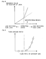
- Fig. 3 is a view showing the relation between the operating state of the internal combustion engine 1 and a required value of an amount of addition of urea.
- the operating state of the internal combustion engine 1 on the axis of abscissa is the engine rotation speed or the engine load.
- the required value of the amount of addition of urea on the axis of ordinate is a required value of the amount of urea to be added from the addition valve 6, and is calculated based on the detection value of the first NOx sensor 12. That is, an amount of urea without excess or deficiency to reduce the amount of NOx obtained based on the detection value of the first NOx sensor 12 is the required value of the amount of addition of urea.
- an alternate long and short dash line represents an operating state in which the flow rate of the exhaust gas becomes the predetermined flow rate.
- the concentration of NOx detected by the first NOx sensor 12 (hereinafter, also referred to as the detected concentration of NOx) becomes higher, as compared with the actual concentration of NOx (hereinafter, also referred to as the actual concentration of NOx).
- a broken line represents a required value of the amount of addition of urea which corresponds to the actual concentration of NOx
- a solid line represents a required value of the amount of addition of urea which corresponds to the detected concentration of NOx.
- Fig. 4 is a view showing the relation between the flow rate of exhaust gas and the turn-around ratio of exhaust gas.
- the turn-around ratio is a rate of the amount of the exhaust gas which can not pass through the opening portion 42, with respect to the amount of the exhaust gas flowing through in front of the opening portion 42.
- An alternate long and short dash line represents the predetermined flow rate.
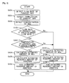
- Fig. 5 is a flow chart showing a flow for reducing agent addition control according to the first embodiment of the present invention. This flow or routine is carried out by means of the ECU 10 at each predetermined time interval.
- step S101 the flow rate of the exhaust gas is detected. This is the flow rate of the exhaust gas discharged from the internal combustion engine 1, or the flow rate of the exhaust gas flowing into the NOx catalyst 5.
- the flow rate of the exhaust gas has a relation with the amount of intake air which is detected, for example, by the air flow meter 15, and hence, is calculated based on the amount of intake air thus detected.
- step S102 the concentration of NOx is detected.
- the concentration of NOx thus detected is a value obtained by actually detecting the concentration of NOx in the exhaust gas discharged from the internal combustion engine 1, and is the detection value of the first NOx sensor 12. That is, the detected concentration of NOx has been obtained in this step.
- step S103 it is determined whether the flow rate of the exhaust gas detected in step S101 is equal to or more than the predetermined flow rate. In this step, it is determined whether the exhaust gas is in a state where the first NOx catalyst 12 is able to detect ammonia. According to this, it is determined whether the detection value of the first NOx sensor 12 is used. In cases where an affirmative determination is made in step S103, the routine goes to step S104, whereas in cases where a negative determination is made, the routine goes to step S107.
- an estimated amount of NOx is calculated.
- the estimated amount of NOx is an estimated value of the amount of NOx in the exhaust gas discharged from the internal combustion engine 1 per unit time, and is calculated based on the operating state of the internal combustion engine 1 (e.g., the engine rotation speed, the engine load, etc.).
- the operating state of the internal combustion engine 1 e.g., the engine rotation speed, the engine load, etc.
- the relation between the operating state of the internal combustion engine 1 and the estimated amount of NOx can be obtained in advance by experiments, simulations, or the like.
- step S105 an estimated required amount of addition is calculated.
- the estimated required amount of addition is a minimum amount of addition of the reducing agent required at least in order to reduce all the estimated amount of NOx calculated in step S104.
- step S106 the estimated required amount of addition calculated in step S105 is added, and thereafter, this flow chart or routine is ended.
- step S107 a detected amount of NOx is calculated.
- the detected amount of NOx is an amount of NOx in the exhaust gas discharged from the internal combustion engine 1 per unit time, and is an amount of NOx calculated based on the flow rate of the exhaust gas detected in step S101, and the detected concentration of NOx detected in step S102.
- step S108 a detected required amount of addition is calculated.
- the detected required amount of addition is a minimum amount of addition of the reducing agent required at least in order to reduce all the detected amount of NOx calculated in step S107.
- step S109 the detected required amount of addition calculated in step S108 is added, and thereafter, this flow chart or routine is ended.
- step S103 in cases where a negative determination is made in step S103, the amount of addition of the reducing agent is calculated, without using the detection value of the first NOx sensor 12. This can be said that the limitation of the calculation is carried out.
- the reducing agent flows backwards due to the pulsation of the exhaust gas when the flow rate of the exhaust gas is small, but in cases where a resistance such as the mixer 4 exists in the exhaust passage 2, the reducing agent can flow backwards when the flow rate of the exhaust gas is large.
- the detection value of the first NOx sensor 12 is made large due to ammonia in the case where the flow rate of the exhaust gas is large, it is possible to suppress the amount of addition of the reducing agent from becoming too large or excessive. As a result of this, it is possible to suppress the reducing agent from passing through the NOx catalyst 5, as well as to reduce the amount of consumption of the reducing agent.
- the distance between the oxidation catalyst to the NOx catalyst 5 can be made short by the provision of the mixer 4, but in the case where the first NOx sensor 12 and the addition valve 6 are provided between the oxidation catalyst 3 and the NOx catalyst 5, the distance between the first NOx sensor 12 and the addition valve 6 becomes close. For this reason, the influence of the reducing agent being caused to flow backwards by the mixer 4 may become large. However, in the exhaust gas purification apparatus with such an arrangement, the effect or advantage of the present invention becomes much larger.
- the limitation of the calculation is carried out according to the flow rate of the exhaust gas, but instead of this, the limitation of the calculation may be carried out according to the engine rotation speed or the engine load.
- the flow rate of the exhaust gas changes with the engine rotation speed and the engine load. The higher the engine rotation speed, and the higher the engine load, the larger the flow rate of the exhaust gas becomes. Accordingly, when the engine rotation speed is equal to or more than a predetermined speed, or when the engine load is equal to or more than a predetermined load, the limitation of the calculation may be carried out.
- the predetermined speed and the predetermined load can be obtained in advance by experiments, simulations or the like, as a value at which the reducing agent can arrive at the first NOx sensor 12.
- the amount of addition of the reducing agent is calculated based on the estimated amount of NOx.
- the detected amount of NOx may be calculated after correcting the detection value of the first NOx sensor 12, and then, the detected required amount of addition may be calculated based on the detected amount of NOx thus calculated.
- the detected required amount of addition may be corrected.
- step S106 the reducing agent is added by adjusting the amount of addition of the reducing agent to the estimated required amount of addition, but instead of this, the addition of the reducing agent may be inhibited.
- the rate of NOx reduction can be calculated by using the detection value of the first NOx sensor 12 and the detection value of the second NOx sensor 13, and then, the abnormality diagnosis of the NOx catalyst 5 can be carried out by using the rate of NOx reduction thus obtained.
- the erroneous diagnosis can be suppressed by inhibiting the calculation of the rate of NOx reduction using the detection value of the first NOx sensor 12, or by inhibiting the abnormality diagnosis using the detection value of the first NOx sensor 12.
- the rate of NOx reduction may be calculated, and then, the rate of NOx reduction thus calculated may be corrected.
- the mixer 4 has been explained as an example of the channel cross section reducing part according to the present invention, but instead of this, a filter for trapping particulate matter in the exhaust gas can also be used as the channel cross section reducing part.
- the NOx catalyst may also be supported by this filter.
- the filter may become resistance, and the exhaust gas may flow backwards, so that the reducing agent can arrive at the first NOx sensor 12.
- only filter may be provided without the provision of the mixer 4, the arrangement may be such that both the mixer 4 and the filter are provided.
- both of the mixer 4 and the filter may also be used in combination as the channel cross section reducing part, or either one of the mixer 4 and the filter may also be used as the channel cross section reducing part.
- the first embodiment it is determined based on the flow rate of the exhaust gas whether the limitation of the calculation is to be carried out, but in this second embodiment, such a determination is made in further consideration of the temperature of the exhaust gas.
- the urea water thus added may arrive at the first NOx sensor 12 in the state of urea before conversion to ammonia. Even if the urea water arrives at the first NOx sensor 12 in the state of urea, the detection value of the first NOx sensor 12 does not change, so there is no problem even if the detection value of the first NOx sensor 12 is used.
- Fig. 6 is a view showing the relation between the temperature of exhaust gas and the amount of generation of ammonia.
- the amount of generation of ammonia is an amount of the ammonia converted from urea.
- An alternate long and short dash line represents a predetermined temperature at which urea is caused to convert to ammonia. At temperatures less than the predetermined temperature at which urea is caused to convert to ammonia, ammonia is not generated. On the other hand, at temperatures equal to or higher than the predetermined temperature, ammonia is generated, and in addition, the higher the temperature, the larger the amount of generation of ammonia becomes.
- Fig. 7 is a flow chart showing a flow for reducing agent addition control according to the second embodiment of the present invention. This flow or routine is carried out by means of the ECU 10 at each predetermined time interval.
- This flow or routine is carried out by means of the ECU 10 at each predetermined time interval.
- step S201 the temperature of the exhaust gas is detected.
- the temperature of the exhaust gas is detected by the temperature sensor 11.
- step S202 it is determined whether the temperature of the exhaust gas detected in step S201 is equal to or higher than the predetermined temperature.
- the predetermined temperature is a temperature at which urea converts to ammonia. That is, in this step, it is determined whether urea converts to ammonia.
- the limitation of the calculation is carried out.
- the reducing agent is added by using the detection value of the first NOx sensor 12.
- the temperature of the exhaust gas relates to the operating state of the internal combustion engine 1, so it is also possible to estimate the temperature of the exhaust gas based on the operating state of the internal combustion engine 1. Accordingly, the temperature sensor 11 can also be omitted. In addition, the temperature of the wall of the exhaust passage 2 can also be used in place of the temperature of the exhaust gas. Moreover, in cases where the temperature of the exhaust gas is equal to or higher than the predetermined temperature, the detection value of the first NOx sensor 12 may be corrected based on the temperature of the exhaust gas.
- the higher the temperature of the exhaust gas the higher the proportion of the urea which converts to ammonia becomes, and so, the larger the detection value of the first NOx sensor 12 becomes.
- correction may be made in such a manner that the higher the temperature of the exhaust gas, the smaller the detection value of the first NOx sensor 12 becomes.
- the relation between the temperature of the exhaust gas and the corrected value of the detection value of the first NOx sensor 12 has been obtained in advance by experiments, simulations, or the like.
- the amount of addition of the reducing agent or the rate of NOx reduction calculated based on the detection value of the first NOx sensor 12 may be corrected.
- the rate of NOx reduction for example, the larger the flow rate of the exhaust gas, or the higher the temperature of the exhaust gas, the more ammonia tends to be detected by the first NOx sensor 12.
- This correction value or correction coefficient can be obtained in advance through experiments, simulations, or the like.
- the detection value of the first NOx sensor 12 is not affected by the influence of ammonia.
- the detection value of the first NOx sensor 12 is affected by the influence of ammonia, an amount of change of the detection value is as small as can be ignored. Accordingly, in this third embodiment, the limitation of the calculation is carried out only in cases where the detection value of the first NOx sensor 12 changes under the influence of ammonia to such an extent as can not be ignored.
- Fig. 8 is a flow chart showing a flow for reducing agent addition control according to the third embodiment of the present invention. This flow or routine is carried out by means of the ECU 10 at each predetermined time interval.
- This flow or routine is carried out by means of the ECU 10 at each predetermined time interval.
- step S102 when the processing of step S102 is completed, step S107 and step S108 are processed, and thereafter, the routine further goes to step S103.
- step S201 and step S202 can also be omitted.
- step S301 it is determined whether the detected required amount of addition is equal to or more than a value which is the sum of the estimated required amount of addition and the threshold value of the amount of reducing agent.
- the threshold value of the amount of reducing agent referred to herein is a value which represents the boundary of whether ammonia has been detected by the first NOx sensor 12.
- the threshold value of the amount of reducing agent may also be an increase of the detected required amount of addition due to the ammonia in the case where the detected required amount of addition is affected by the influence of ammonia.
- step S103 and step S202 Even when an affirmative determination is made in each of step S103 and step S202, the detected required amount of addition is added, if the detected required amount of addition is not larger, by the threshold value of the amount of reducing agent or more, than the estimated required amount of addition. In cases where an affirmative determination is made in step S301, the routine goes to step S106, whereas in cases where a negative determination is made, the routine goes to step S109.
- the limitation of the calculation may be carried out.
- the estimated concentration of NOx is a value which estimates a concentration of NOx at the upstream side of the first NOx sensor 12 or in the vicinity of the first NOx sensor 12.
- the estimated concentration of NOx can also be said as a value which estimates the concentration of NOx detected by the first NOx sensor 12. Then, by making a comparison between the detected concentration of NOx and the estimated concentration of NOx, it is determined whether the detection value of the first NOx sensor 12 is affected by the influence of ammonia.
- Fig. 9 is a flow chart showing a flow for reducing agent addition control according to the third embodiment of the present invention. This flow or routine is carried out by means of the ECU 10 at each predetermined time interval.
- step S201 and step S202 can be omitted.
- step S401 the estimated concentration of NOx is calculated.
- the estimated concentration of NOx is an estimated value of the concentration of NOx in the exhaust gas discharged from the internal combustion engine 1, and is calculated based on the operating state of the internal combustion engine 1 (e.g., the engine rotation speed, the engine load, etc.).
- the operating state of the internal combustion engine 1 e.g., the engine rotation speed, the engine load, etc.
- the relation between the operating state of the internal combustion engine 1 and the estimated concentration of NOx can be obtained in advance by experiments, simulations, or the like.
- step S402 it is determined whether the detected concentration of NOx is equal to or more than a value which is the sum of the estimated concentration of NOx and the threshold value of the concentration of NOx.
- the threshold value of the concentration of NOx referred to herein is a value which represents the boundary of whether ammonia has been detected by the first NOx sensor 12.
- the threshold value of the concentration of NOx may also be an increase of the detected concentration of NOx due to the ammonia in the case where the detected concentration of NOx is affected by the influence of ammonia.
- step S103 and step S202 Even when an affirmative determination is made in each of step S103 and step S202, the detected required amount of addition is added, if the detected concentration of NOx is not higher, by the threshold value of the concentration of NOx or more, than the estimated concentration of NOx. In cases where an affirmative determination is made in step S402, the routine goes to step S106, whereas in cases where a negative determination is made, the routine goes to step S109.
- the limitation of the calculation is carried out. That is, by making a comparison between the detected amount of NOx and the estimated amount of NOx, it is determined whether the detection value of the first NOx sensor 12 is affected by the influence of ammonia.
- Fig. 10 is a flow chart showing a flow for reducing agent addition control according to the third embodiment of the present invention. This flow or routine is carried out by means of the ECU 10 at each predetermined time interval.
- step S201 and step S202 can be omitted.
- step S501 it is determined whether the detected amount of NOx is equal to or more than a value which is the sum of the estimated amount of NOx and the threshold value of the amount of NOx.
- the threshold value of the amount of NOx referred to herein is a value which represents the boundary of whether ammonia has been detected by the first NOx sensor 12.
- the threshold value of the amount of NOx may also be an increase of the detected amount of NOx due to the ammonia in the case where the detected amount of NOx is affected by the influence of ammonia.
- step S103 and step S202 Even when an affirmative determination is made in each of step S103 and step S202, the detected required amount of addition is added, if the detected amount of NOx is not larger, by the threshold value of the amount of NOx or more, than the estimated amount of NOx. In cases where an affirmative determination is made in step S501, the routine goes to step S106, whereas in cases where a negative determination is made, the routine goes to step S109.
- the limitation of the calculation may be carried out.
- Ammonia in the exhaust gas is adsorbed to the NOx catalyst 5, and hence, even in a state where ammonia is detected in the first NOx sensor 12, ammonia is hardly detected in the second NOx sensor 13. Accordingly, when the detection value of the first NOx sensor 12 becomes high under the influence of ammonia, the detected rate of NOx reduction will become high. For this reason, by making a comparison between the detected rate of NOx reduction and the estimated rate of NOx reduction, it is determined whether the detection value of the first NOx sensor 12 is affected by the influence of ammonia.
- Fig. 11 is a flow chart showing a flow for reducing agent addition control according to the third embodiment of the present invention. This flow or routine is carried out by means of the ECU 10 at each predetermined time interval.
- step S201 and step S202 can be omitted.
- step S108 when the processing of step S108 is completed, the routine goes to step S601.
- step S601 NOx is detected by the second NOx sensor 12.
- the concentration of NOx detected at this time is set as a second concentration of NOx.
- step S602 where the detected rate of NOx reduction is calculated.
- step S103 the routine goes to step S103.
- step S603 the estimated rate of NOx reduction is calculated.
- the rate of NOx reduction in the NOx catalyst 5 is associated with the temperature of the NOx catalyst 5 (this may also be the temperature of the exhaust gas) and the flow rate of the exhaust gas (this may also be the amount of intake air), and hence, the relation between these factors can have been obtained and stored in advance through experiments, simulations, or the like, thereby making it possible to calculate the estimated rate of NOx reduction.
- the temperature of the NOx catalyst 5 and the flow rate of the exhaust gas may be estimated based on the number of engine revolutions per unit time and the engine load. It can be said that in this step S603, the estimated rate of NOx reduction is calculated based on the operating state of the internal combustion engine 1.
- step S604 it is determined whether the detected rate of NOx reduction is equal to or more than a value which is the sum of the estimated rate of NOx reduction and the threshold value of the rate of NOx reduction.
- the threshold value of the rate of NOx reduction referred to herein is a value which represents the boundary of whether ammonia has been detected by the first NOx sensor 12.
- the threshold value of the rate of NOx reduction may also be an increase of the detected rate of NOx reduction due to the ammonia in the case where the detected rate of NOx reduction is affected by the influence of ammonia.
- step S103 Even when an affirmative determination is made in each of step S103 and step S202, the detected required amount of addition is added, if the detected rate of NOx reduction is not higher, by the threshold value of the rate of NOx reduction or more, than the estimated rate of NOx reduction.
- step S604 the routine goes to step S106, whereas in cases where a negative determination is made, the routine goes to step S109.
- the larger the flow rate of the exhaust gas the larger a correction value or a correction coefficient for the rate of NOx reduction may be made.
- This correction value or correction coefficient can be obtained in advance through experiments, simulations, or the like.
- the rate of NOx reduction is calculated by using the detection value of the first NOx sensor 12.
- an explanation has been given by mentioning, as examples, the required amount of addition, the concentration of NOx, the amount of NOx, and the rate of NOx reduction. On the other hand, even in the case of other physical quantities, they can be applied.
- a difference between a physical quantity (hereinafter, also referred to as a detected physical quantity), which is correlated with the detection value of the first NOx sensor 12 and which increases in accordance with the increasing detection value of the first NOx sensor 12, and an estimated value (hereinafter, also referred to as an estimated physical quantity) of the physical quantity calculated based on the operating state of the internal combustion engine 1 is equal to or larger than a threshold value, the limitation of the calculation can be carried out.
- Fig. 12 is a view showing the schematic construction of an intake system and an exhaust system of an internal combustion engine 1 according to a fourth embodiment of the present invention.
- a turbocharger 20 is arranged at the upstream side of the oxidation catalyst 3.
- the other devices, parts and so on are the same as those in the above-mentioned embodiments, so the explanation thereof is omitted.
- Fig. 13 is a view showing the flow of exhaust gas downstream of the turbocharger 20 by a broken line.
- the exhaust gas swirls around the central axis of the exhaust passage 2.
- the exhaust gas is deviated or displaced in the direction of the wall surface of the exhaust passage 2 due to a centrifugal force generated at this time.
- the larger the flow rate of the exhaust gas the more remarkable this deviation or displacement becomes.
- the pressure at the side of the central axis of the exhaust passage 2 becomes relatively lower than that at the side of the wall surface of the exhaust passage 2.
Landscapes
- Engineering & Computer Science (AREA)
- Chemical & Material Sciences (AREA)
- Chemical Kinetics & Catalysis (AREA)
- Combustion & Propulsion (AREA)
- Health & Medical Sciences (AREA)
- General Engineering & Computer Science (AREA)
- Mechanical Engineering (AREA)
- Toxicology (AREA)
- Biomedical Technology (AREA)
- Environmental & Geological Engineering (AREA)
- Analytical Chemistry (AREA)
- General Chemical & Material Sciences (AREA)
- Oil, Petroleum & Natural Gas (AREA)
- Exhaust Gas After Treatment (AREA)
- Exhaust Gas Treatment By Means Of Catalyst (AREA)
Applications Claiming Priority (2)
| Application Number | Priority Date | Filing Date | Title |
|---|---|---|---|
| JP2014103589 | 2014-05-19 | ||
| JP2015080175A JP6252540B2 (ja) | 2014-05-19 | 2015-04-09 | 内燃機関の排気浄化装置 |
Publications (2)
| Publication Number | Publication Date |
|---|---|
| EP2947294A1 true EP2947294A1 (fr) | 2015-11-25 |
| EP2947294B1 EP2947294B1 (fr) | 2017-11-15 |
Family
ID=53189709
Family Applications (1)
| Application Number | Title | Priority Date | Filing Date |
|---|---|---|---|
| EP15168225.9A Not-in-force EP2947294B1 (fr) | 2014-05-19 | 2015-05-19 | Appareil de purification de gaz d'échappement pour moteur à combustion interne |
Country Status (3)
| Country | Link |
|---|---|
| US (1) | US9884292B2 (fr) |
| EP (1) | EP2947294B1 (fr) |
| JP (1) | JP6252540B2 (fr) |
Families Citing this family (4)
| Publication number | Priority date | Publication date | Assignee | Title |
|---|---|---|---|---|
| CN108027579B (zh) | 2015-09-15 | 2021-06-22 | Ntn株式会社 | 剥离部件及其制造方法 |
| US11293328B2 (en) * | 2020-06-16 | 2022-04-05 | Faurecia Emissions Control Technologies, Usa, Llc | Mixer baffle with integrated sensor |
| CN114263521B (zh) * | 2021-12-31 | 2023-03-21 | 潍柴动力股份有限公司 | 一种传感器参数的修正方法及装置 |
| DK182158B1 (en) * | 2024-03-13 | 2025-09-24 | Everllence Filial Af Everllence Se Tyskland | A LARGE TWO-STROKE UNIFLOW SCAVENGED TURBOCHARGED INTERNAL COMBUSTION ENGINE WITH AN SCR REACTOR FOR REDUCING NOx EMISSIONS AND METHOD FOR CONTROLLING NOx REDUCTION IN SUCH ENGINE |
Citations (4)
| Publication number | Priority date | Publication date | Assignee | Title |
|---|---|---|---|---|
| US6119448A (en) * | 1997-08-21 | 2000-09-19 | Man Nutzfahrzeuge Ag | Method for metering a reducing agent into NOx -containing exhaust gas of an internal combustion engine |
| US7543443B2 (en) * | 2004-07-23 | 2009-06-09 | Hino Motors, Ltd. | Method for determining NOx reduction ratio in exhaust emission control device |
| WO2010146285A1 (fr) | 2009-06-19 | 2010-12-23 | Faurecia Systemes D'echappement | Ligne d'échappement avec système d'injection |
| WO2011033620A1 (fr) | 2009-09-16 | 2011-03-24 | トヨタ自動車株式会社 | Dispositif de purification de gaz d'échappement et procédé pour moteur à combustion interne |
Family Cites Families (3)
| Publication number | Priority date | Publication date | Assignee | Title |
|---|---|---|---|---|
| JP2009180150A (ja) * | 2008-01-30 | 2009-08-13 | Toyota Motor Corp | 排気ガス浄化システムに用いられるNOxセンサの異常判定装置 |
| JP2010185372A (ja) * | 2009-02-12 | 2010-08-26 | Toyota Motor Corp | 内燃機関の排気浄化方法およびその装置 |
| US8904760B2 (en) * | 2009-06-17 | 2014-12-09 | GM Global Technology Operations LLC | Exhaust gas treatment system including an HC-SCR and two-way catalyst and method of using the same |
-
2015
- 2015-04-09 JP JP2015080175A patent/JP6252540B2/ja not_active Expired - Fee Related
- 2015-05-18 US US14/714,380 patent/US9884292B2/en not_active Expired - Fee Related
- 2015-05-19 EP EP15168225.9A patent/EP2947294B1/fr not_active Not-in-force
Patent Citations (5)
| Publication number | Priority date | Publication date | Assignee | Title |
|---|---|---|---|---|
| US6119448A (en) * | 1997-08-21 | 2000-09-19 | Man Nutzfahrzeuge Ag | Method for metering a reducing agent into NOx -containing exhaust gas of an internal combustion engine |
| US7543443B2 (en) * | 2004-07-23 | 2009-06-09 | Hino Motors, Ltd. | Method for determining NOx reduction ratio in exhaust emission control device |
| WO2010146285A1 (fr) | 2009-06-19 | 2010-12-23 | Faurecia Systemes D'echappement | Ligne d'échappement avec système d'injection |
| WO2011033620A1 (fr) | 2009-09-16 | 2011-03-24 | トヨタ自動車株式会社 | Dispositif de purification de gaz d'échappement et procédé pour moteur à combustion interne |
| US20120174562A1 (en) * | 2009-09-16 | 2012-07-12 | Toyota Jidosha Kabushiki Kaisha | Exhaust gas purification apparatus and exhaust gas purification method for an internal combustion engine |
Also Published As
| Publication number | Publication date |
|---|---|
| JP6252540B2 (ja) | 2017-12-27 |
| JP2016000990A (ja) | 2016-01-07 |
| US9884292B2 (en) | 2018-02-06 |
| US20150328585A1 (en) | 2015-11-19 |
| EP2947294B1 (fr) | 2017-11-15 |
Similar Documents
| Publication | Publication Date | Title |
|---|---|---|
| CN101918686B (zh) | 催化剂劣化判定装置及催化剂劣化判定方法 | |
| EP3106640B1 (fr) | Appareil et procédé de diagnostic de défaillance | |
| EP2141331B1 (fr) | Dispositif de purification d'échappement pour moteur à combustion interne | |
| JP6090257B2 (ja) | 内燃機関の排気浄化装置 | |
| US8091343B2 (en) | Exhaust gas purification apparatus for internal combustion engine | |
| JP5839118B2 (ja) | 内燃機関の排気浄化装置の異常判定システム | |
| US9884292B2 (en) | Exhaust gas purification apparatus for an internal combustion engine | |
| EP2759681B1 (fr) | Dispositif de purification des gaz d'échappement pour un moteur à combustion interne | |
| JP5240065B2 (ja) | 排気浄化装置の故障検出装置 | |
| EP2940267A1 (fr) | Dispositif d'épuration des gaz d'échappement pour moteur à combustion interne | |
| US9594065B2 (en) | Apparatus for detecting deterioration of NOx selective reduction catalyst | |
| US9938876B2 (en) | Abnormality diagnosis device for exhaust gas purification apparatus in internal combustion engine | |
| CN104870764A (zh) | 内燃机的排气净化装置 | |
| EP2905443B1 (fr) | Appareil de purification de gaz d'échappement pour moteur à combustion interne | |
| EP2759682A1 (fr) | Dispositif d'épuration de l'échappement pour moteur à combustion interne | |
| JP6631479B2 (ja) | 内燃機関の排気浄化装置の異常診断装置 | |
| US9593610B2 (en) | Exhaust gas purification system for internal combustion engine | |
| JP4894622B2 (ja) | 内燃機関の排気浄化装置 | |
| JP2018178734A (ja) | 内燃機関の排気浄化システム | |
| JP2016079903A (ja) | 内燃機関の排気浄化装置の故障判定装置 | |
| JP2010133375A (ja) | センサの出力補正装置及びセンサの出力補正方法 | |
| JP2010048115A (ja) | 内燃機関の触媒劣化判定装置 |
Legal Events
| Date | Code | Title | Description |
|---|---|---|---|
| PUAI | Public reference made under article 153(3) epc to a published international application that has entered the european phase |
Free format text: ORIGINAL CODE: 0009012 |
|
| 17P | Request for examination filed |
Effective date: 20150519 |
|
| AK | Designated contracting states |
Kind code of ref document: A1 Designated state(s): AL AT BE BG CH CY CZ DE DK EE ES FI FR GB GR HR HU IE IS IT LI LT LU LV MC MK MT NL NO PL PT RO RS SE SI SK SM TR |
|
| AX | Request for extension of the european patent |
Extension state: BA ME |
|
| RIC1 | Information provided on ipc code assigned before grant |
Ipc: B01D 53/94 20060101ALI20170524BHEP Ipc: F01N 3/20 20060101AFI20170524BHEP |
|
| GRAP | Despatch of communication of intention to grant a patent |
Free format text: ORIGINAL CODE: EPIDOSNIGR1 |
|
| STAA | Information on the status of an ep patent application or granted ep patent |
Free format text: STATUS: GRANT OF PATENT IS INTENDED |
|
| INTG | Intention to grant announced |
Effective date: 20170712 |
|
| RIN1 | Information on inventor provided before grant (corrected) |
Inventor name: ASAURA, SHINYA |
|
| GRAS | Grant fee paid |
Free format text: ORIGINAL CODE: EPIDOSNIGR3 |
|
| GRAA | (expected) grant |
Free format text: ORIGINAL CODE: 0009210 |
|
| STAA | Information on the status of an ep patent application or granted ep patent |
Free format text: STATUS: THE PATENT HAS BEEN GRANTED |
|
| AK | Designated contracting states |
Kind code of ref document: B1 Designated state(s): AL AT BE BG CH CY CZ DE DK EE ES FI FR GB GR HR HU IE IS IT LI LT LU LV MC MK MT NL NO PL PT RO RS SE SI SK SM TR |
|
| REG | Reference to a national code |
Ref country code: CH Ref legal event code: EP Ref country code: GB Ref legal event code: FG4D Ref country code: AT Ref legal event code: REF Ref document number: 946520 Country of ref document: AT Kind code of ref document: T Effective date: 20171115 |
|
| REG | Reference to a national code |
Ref country code: IE Ref legal event code: FG4D |
|
| REG | Reference to a national code |
Ref country code: DE Ref legal event code: R096 Ref document number: 602015005949 Country of ref document: DE |
|
| REG | Reference to a national code |
Ref country code: DE Ref legal event code: R084 Ref document number: 602015005949 Country of ref document: DE |
|
| REG | Reference to a national code |
Ref country code: GB Ref legal event code: 746 Effective date: 20180223 Ref country code: NL Ref legal event code: MP Effective date: 20171115 |
|
| REG | Reference to a national code |
Ref country code: LT Ref legal event code: MG4D |
|
| REG | Reference to a national code |
Ref country code: FR Ref legal event code: PLFP Year of fee payment: 4 |
|
| REG | Reference to a national code |
Ref country code: AT Ref legal event code: MK05 Ref document number: 946520 Country of ref document: AT Kind code of ref document: T Effective date: 20171115 |
|
| PG25 | Lapsed in a contracting state [announced via postgrant information from national office to epo] |
Ref country code: SE Free format text: LAPSE BECAUSE OF FAILURE TO SUBMIT A TRANSLATION OF THE DESCRIPTION OR TO PAY THE FEE WITHIN THE PRESCRIBED TIME-LIMIT Effective date: 20171115 Ref country code: LT Free format text: LAPSE BECAUSE OF FAILURE TO SUBMIT A TRANSLATION OF THE DESCRIPTION OR TO PAY THE FEE WITHIN THE PRESCRIBED TIME-LIMIT Effective date: 20171115 Ref country code: FI Free format text: LAPSE BECAUSE OF FAILURE TO SUBMIT A TRANSLATION OF THE DESCRIPTION OR TO PAY THE FEE WITHIN THE PRESCRIBED TIME-LIMIT Effective date: 20171115 Ref country code: NO Free format text: LAPSE BECAUSE OF FAILURE TO SUBMIT A TRANSLATION OF THE DESCRIPTION OR TO PAY THE FEE WITHIN THE PRESCRIBED TIME-LIMIT Effective date: 20180215 Ref country code: ES Free format text: LAPSE BECAUSE OF FAILURE TO SUBMIT A TRANSLATION OF THE DESCRIPTION OR TO PAY THE FEE WITHIN THE PRESCRIBED TIME-LIMIT Effective date: 20171115 Ref country code: NL Free format text: LAPSE BECAUSE OF FAILURE TO SUBMIT A TRANSLATION OF THE DESCRIPTION OR TO PAY THE FEE WITHIN THE PRESCRIBED TIME-LIMIT Effective date: 20171115 |
|
| PG25 | Lapsed in a contracting state [announced via postgrant information from national office to epo] |
Ref country code: BG Free format text: LAPSE BECAUSE OF FAILURE TO SUBMIT A TRANSLATION OF THE DESCRIPTION OR TO PAY THE FEE WITHIN THE PRESCRIBED TIME-LIMIT Effective date: 20180215 Ref country code: GR Free format text: LAPSE BECAUSE OF FAILURE TO SUBMIT A TRANSLATION OF THE DESCRIPTION OR TO PAY THE FEE WITHIN THE PRESCRIBED TIME-LIMIT Effective date: 20180216 Ref country code: RS Free format text: LAPSE BECAUSE OF FAILURE TO SUBMIT A TRANSLATION OF THE DESCRIPTION OR TO PAY THE FEE WITHIN THE PRESCRIBED TIME-LIMIT Effective date: 20171115 Ref country code: HR Free format text: LAPSE BECAUSE OF FAILURE TO SUBMIT A TRANSLATION OF THE DESCRIPTION OR TO PAY THE FEE WITHIN THE PRESCRIBED TIME-LIMIT Effective date: 20171115 Ref country code: LV Free format text: LAPSE BECAUSE OF FAILURE TO SUBMIT A TRANSLATION OF THE DESCRIPTION OR TO PAY THE FEE WITHIN THE PRESCRIBED TIME-LIMIT Effective date: 20171115 Ref country code: AT Free format text: LAPSE BECAUSE OF FAILURE TO SUBMIT A TRANSLATION OF THE DESCRIPTION OR TO PAY THE FEE WITHIN THE PRESCRIBED TIME-LIMIT Effective date: 20171115 |
|
| PG25 | Lapsed in a contracting state [announced via postgrant information from national office to epo] |
Ref country code: EE Free format text: LAPSE BECAUSE OF FAILURE TO SUBMIT A TRANSLATION OF THE DESCRIPTION OR TO PAY THE FEE WITHIN THE PRESCRIBED TIME-LIMIT Effective date: 20171115 Ref country code: DK Free format text: LAPSE BECAUSE OF FAILURE TO SUBMIT A TRANSLATION OF THE DESCRIPTION OR TO PAY THE FEE WITHIN THE PRESCRIBED TIME-LIMIT Effective date: 20171115 Ref country code: SK Free format text: LAPSE BECAUSE OF FAILURE TO SUBMIT A TRANSLATION OF THE DESCRIPTION OR TO PAY THE FEE WITHIN THE PRESCRIBED TIME-LIMIT Effective date: 20171115 Ref country code: CZ Free format text: LAPSE BECAUSE OF FAILURE TO SUBMIT A TRANSLATION OF THE DESCRIPTION OR TO PAY THE FEE WITHIN THE PRESCRIBED TIME-LIMIT Effective date: 20171115 Ref country code: CY Free format text: LAPSE BECAUSE OF FAILURE TO SUBMIT A TRANSLATION OF THE DESCRIPTION OR TO PAY THE FEE WITHIN THE PRESCRIBED TIME-LIMIT Effective date: 20171115 |
|
| REG | Reference to a national code |
Ref country code: DE Ref legal event code: R097 Ref document number: 602015005949 Country of ref document: DE |
|
| PG25 | Lapsed in a contracting state [announced via postgrant information from national office to epo] |
Ref country code: PL Free format text: LAPSE BECAUSE OF FAILURE TO SUBMIT A TRANSLATION OF THE DESCRIPTION OR TO PAY THE FEE WITHIN THE PRESCRIBED TIME-LIMIT Effective date: 20171115 Ref country code: SM Free format text: LAPSE BECAUSE OF FAILURE TO SUBMIT A TRANSLATION OF THE DESCRIPTION OR TO PAY THE FEE WITHIN THE PRESCRIBED TIME-LIMIT Effective date: 20171115 Ref country code: IT Free format text: LAPSE BECAUSE OF FAILURE TO SUBMIT A TRANSLATION OF THE DESCRIPTION OR TO PAY THE FEE WITHIN THE PRESCRIBED TIME-LIMIT Effective date: 20171115 Ref country code: RO Free format text: LAPSE BECAUSE OF FAILURE TO SUBMIT A TRANSLATION OF THE DESCRIPTION OR TO PAY THE FEE WITHIN THE PRESCRIBED TIME-LIMIT Effective date: 20171115 |
|
| PLBE | No opposition filed within time limit |
Free format text: ORIGINAL CODE: 0009261 |
|
| STAA | Information on the status of an ep patent application or granted ep patent |
Free format text: STATUS: NO OPPOSITION FILED WITHIN TIME LIMIT |
|
| 26N | No opposition filed |
Effective date: 20180817 |
|
| PG25 | Lapsed in a contracting state [announced via postgrant information from national office to epo] |
Ref country code: SI Free format text: LAPSE BECAUSE OF FAILURE TO SUBMIT A TRANSLATION OF THE DESCRIPTION OR TO PAY THE FEE WITHIN THE PRESCRIBED TIME-LIMIT Effective date: 20171115 |
|
| REG | Reference to a national code |
Ref country code: CH Ref legal event code: PL |
|
| REG | Reference to a national code |
Ref country code: BE Ref legal event code: MM Effective date: 20180531 |
|
| PG25 | Lapsed in a contracting state [announced via postgrant information from national office to epo] |
Ref country code: MC Free format text: LAPSE BECAUSE OF FAILURE TO SUBMIT A TRANSLATION OF THE DESCRIPTION OR TO PAY THE FEE WITHIN THE PRESCRIBED TIME-LIMIT Effective date: 20171115 |
|
| REG | Reference to a national code |
Ref country code: IE Ref legal event code: MM4A |
|
| PG25 | Lapsed in a contracting state [announced via postgrant information from national office to epo] |
Ref country code: LI Free format text: LAPSE BECAUSE OF NON-PAYMENT OF DUE FEES Effective date: 20180531 Ref country code: CH Free format text: LAPSE BECAUSE OF NON-PAYMENT OF DUE FEES Effective date: 20180531 |
|
| PG25 | Lapsed in a contracting state [announced via postgrant information from national office to epo] |
Ref country code: LU Free format text: LAPSE BECAUSE OF NON-PAYMENT OF DUE FEES Effective date: 20180519 |
|
| PG25 | Lapsed in a contracting state [announced via postgrant information from national office to epo] |
Ref country code: IE Free format text: LAPSE BECAUSE OF NON-PAYMENT OF DUE FEES Effective date: 20180519 |
|
| PG25 | Lapsed in a contracting state [announced via postgrant information from national office to epo] |
Ref country code: BE Free format text: LAPSE BECAUSE OF NON-PAYMENT OF DUE FEES Effective date: 20180531 |
|
| PG25 | Lapsed in a contracting state [announced via postgrant information from national office to epo] |
Ref country code: MT Free format text: LAPSE BECAUSE OF NON-PAYMENT OF DUE FEES Effective date: 20180519 |
|
| PG25 | Lapsed in a contracting state [announced via postgrant information from national office to epo] |
Ref country code: TR Free format text: LAPSE BECAUSE OF FAILURE TO SUBMIT A TRANSLATION OF THE DESCRIPTION OR TO PAY THE FEE WITHIN THE PRESCRIBED TIME-LIMIT Effective date: 20171115 |
|
| PG25 | Lapsed in a contracting state [announced via postgrant information from national office to epo] |
Ref country code: PT Free format text: LAPSE BECAUSE OF FAILURE TO SUBMIT A TRANSLATION OF THE DESCRIPTION OR TO PAY THE FEE WITHIN THE PRESCRIBED TIME-LIMIT Effective date: 20171115 |
|
| PG25 | Lapsed in a contracting state [announced via postgrant information from national office to epo] |
Ref country code: MK Free format text: LAPSE BECAUSE OF NON-PAYMENT OF DUE FEES Effective date: 20171115 Ref country code: HU Free format text: LAPSE BECAUSE OF FAILURE TO SUBMIT A TRANSLATION OF THE DESCRIPTION OR TO PAY THE FEE WITHIN THE PRESCRIBED TIME-LIMIT; INVALID AB INITIO Effective date: 20150519 |
|
| PG25 | Lapsed in a contracting state [announced via postgrant information from national office to epo] |
Ref country code: AL Free format text: LAPSE BECAUSE OF FAILURE TO SUBMIT A TRANSLATION OF THE DESCRIPTION OR TO PAY THE FEE WITHIN THE PRESCRIBED TIME-LIMIT Effective date: 20171115 Ref country code: IS Free format text: LAPSE BECAUSE OF FAILURE TO SUBMIT A TRANSLATION OF THE DESCRIPTION OR TO PAY THE FEE WITHIN THE PRESCRIBED TIME-LIMIT Effective date: 20180315 |
|
| PGFP | Annual fee paid to national office [announced via postgrant information from national office to epo] |
Ref country code: FR Payment date: 20210412 Year of fee payment: 7 |
|
| PGFP | Annual fee paid to national office [announced via postgrant information from national office to epo] |
Ref country code: GB Payment date: 20210422 Year of fee payment: 7 |
|
| PGFP | Annual fee paid to national office [announced via postgrant information from national office to epo] |
Ref country code: DE Payment date: 20220322 Year of fee payment: 8 |
|
| GBPC | Gb: european patent ceased through non-payment of renewal fee |
Effective date: 20220519 |
|
| PG25 | Lapsed in a contracting state [announced via postgrant information from national office to epo] |
Ref country code: FR Free format text: LAPSE BECAUSE OF NON-PAYMENT OF DUE FEES Effective date: 20220531 |
|
| PG25 | Lapsed in a contracting state [announced via postgrant information from national office to epo] |
Ref country code: GB Free format text: LAPSE BECAUSE OF NON-PAYMENT OF DUE FEES Effective date: 20220519 |
|
| P01 | Opt-out of the competence of the unified patent court (upc) registered |
Effective date: 20230427 |
|
| REG | Reference to a national code |
Ref country code: DE Ref legal event code: R119 Ref document number: 602015005949 Country of ref document: DE |
|
| PG25 | Lapsed in a contracting state [announced via postgrant information from national office to epo] |
Ref country code: DE Free format text: LAPSE BECAUSE OF NON-PAYMENT OF DUE FEES Effective date: 20231201 |