EP2947407A2 - Bewegliches facheinrücksystem für haushaltsgeräte, haushaltsgerät mit diesem einrücksystem und bewegliche struktur mit einem beweglichen facheinrücksystem für haushaltsgeräte - Google Patents
Bewegliches facheinrücksystem für haushaltsgeräte, haushaltsgerät mit diesem einrücksystem und bewegliche struktur mit einem beweglichen facheinrücksystem für haushaltsgeräte Download PDFInfo
- Publication number
- EP2947407A2 EP2947407A2 EP15168984.1A EP15168984A EP2947407A2 EP 2947407 A2 EP2947407 A2 EP 2947407A2 EP 15168984 A EP15168984 A EP 15168984A EP 2947407 A2 EP2947407 A2 EP 2947407A2
- Authority
- EP
- European Patent Office
- Prior art keywords
- cooperating
- movable
- movable compartment
- compartment
- skirt
- Prior art date
- Legal status (The legal status is an assumption and is not a legal conclusion. Google has not performed a legal analysis and makes no representation as to the accuracy of the status listed.)
- Granted
Links
- 238000006073 displacement reaction Methods 0.000 claims description 14
- 239000007769 metal material Substances 0.000 claims description 5
- 238000009434 installation Methods 0.000 description 8
- 238000010276 construction Methods 0.000 description 4
- 229910052751 metal Inorganic materials 0.000 description 4
- 238000000638 solvent extraction Methods 0.000 description 4
- 235000013305 food Nutrition 0.000 description 3
- 239000002184 metal Substances 0.000 description 3
- 239000000463 material Substances 0.000 description 2
- 230000003647 oxidation Effects 0.000 description 2
- 238000007254 oxidation reaction Methods 0.000 description 2
- 239000000126 substance Substances 0.000 description 2
- 230000006978 adaptation Effects 0.000 description 1
- 239000000470 constituent Substances 0.000 description 1
- 238000011109 contamination Methods 0.000 description 1
- 230000007613 environmental effect Effects 0.000 description 1
- 235000012055 fruits and vegetables Nutrition 0.000 description 1
- 238000004519 manufacturing process Methods 0.000 description 1
- 230000004048 modification Effects 0.000 description 1
- 238000012986 modification Methods 0.000 description 1
- 238000005457 optimization Methods 0.000 description 1
- 238000005057 refrigeration Methods 0.000 description 1
- 239000012858 resilient material Substances 0.000 description 1
- 238000000926 separation method Methods 0.000 description 1
- 235000013311 vegetables Nutrition 0.000 description 1
Images




Classifications
-
- F—MECHANICAL ENGINEERING; LIGHTING; HEATING; WEAPONS; BLASTING
- F25—REFRIGERATION OR COOLING; COMBINED HEATING AND REFRIGERATION SYSTEMS; HEAT PUMP SYSTEMS; MANUFACTURE OR STORAGE OF ICE; LIQUEFACTION SOLIDIFICATION OF GASES
- F25D—REFRIGERATORS; COLD ROOMS; ICE-BOXES; COOLING OR FREEZING APPARATUS NOT OTHERWISE PROVIDED FOR
- F25D25/00—Charging, supporting, and discharging the articles to be cooled
- F25D25/02—Charging, supporting, and discharging the articles to be cooled by shelves
- F25D25/024—Slidable shelves
- F25D25/025—Drawers
-
- A—HUMAN NECESSITIES
- A47—FURNITURE; DOMESTIC ARTICLES OR APPLIANCES; COFFEE MILLS; SPICE MILLS; SUCTION CLEANERS IN GENERAL
- A47B—TABLES; DESKS; OFFICE FURNITURE; CABINETS; DRAWERS; GENERAL DETAILS OF FURNITURE
- A47B2210/00—General construction of drawers, guides and guide devices
- A47B2210/17—Drawers used in connection with household appliances
- A47B2210/175—Refrigerators or freezers
-
- A—HUMAN NECESSITIES
- A47—FURNITURE; DOMESTIC ARTICLES OR APPLIANCES; COFFEE MILLS; SPICE MILLS; SUCTION CLEANERS IN GENERAL
- A47B—TABLES; DESKS; OFFICE FURNITURE; CABINETS; DRAWERS; GENERAL DETAILS OF FURNITURE
- A47B88/00—Drawers for tables, cabinets or like furniture; Guides for drawers
- A47B88/50—Safety devices or the like for drawers
- A47B88/57—Safety devices or the like for drawers preventing complete withdrawal of the drawer
Definitions
- the present invention refers to a movable compartment engagement system for household appliance, said system being designed, more specifically, for making the engagement of sliding drawers safer and versatile in household refrigerators, besides of allowing the variation of the amount and configuration of compartments of a certain storage space in a completely new fashion when compared with the current state of the art.
- drawers are removable and sliding, constructed in order to cooperate with tracks existing on the walls of the cooled compartment, wherein, in general, said tracks comprise cavities on which the drawers edge structures are simply supported or alternatively casters are attached thereto to facilitate the sliding of the drawers when closing or opening.
- drawers jamming often occurs during closing or opening, since if it is improperly handled - by only one of the user's hands or pushed / pulled by near regions of its sides - there is a horizontal displacement diagonally thereof, resulting in inconvenience that compromise their proper handling.
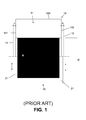
- FIG. 1 schematically illustrates how the misalignment of the refrigerator drawers occurs during the sliding.
- This Figure illustrates, in schematic cross-sectional view, a refrigerator cabinet 10 with an inner compartment 11 comprising side tracks 12 cooperating with its side walls 13, wherein the side tracks 12 slide on the side edges 21 of a movable compartment or drawer 20.
- the horizontal misalignment of the drawer occurs generally due to the clearance afforded by the width "d" of the tracks 12 - which exists to enable the engagement and the movement of the drawer 20 - associated with large longitudinal dimension "D" of the drawer which, as it is inserted into the inner compartment 11, creates an imaginary diagonal displacement trend line that makes up the front surface projection of the cabinet 10 at an angle "a” that increases as the drawer 20 is inserted into the inner compartment 11 and because of this, will increase the possibility of displacing and jamming.
- Document US6945617 describes a track for sliding drawers whose construction results in a horizontal thin span for the passage of the support edge thereof, and although this will be able to reduce the undue horizontal and vertical movement of the drawer, during its opening or closing, it can hinder the sliding thereof, besides requiring the use of metal screws for fixing the refrigerator cabinet inner compartment, making the installation more complex.
- document KR2008029046 discloses a drawer assembling structure which comprises using, between the track and the cabinet surface in which it is installed, a spring which, through the pressure exerted on the track, tends to compensate the horizontal displacement of the drawer and thereby reducing said clearance, and hence the misalignment.
- a spring which, through the pressure exerted on the track, tends to compensate the horizontal displacement of the drawer and thereby reducing said clearance, and hence the misalignment.
- Document JP4254670 discloses a removable structure which allows using, instead of a single large tray, several drawers of different storage capacities. However, it is a horizontal structure which interferes with the entire base of the cooled compartment and on which other drawers are supported, also presenting significant limitation with respect to variability of internal volumes of storage products.
- Document BR PI0504387-5 describes a vertical structure to be engaged within the inner compartment of a refrigerator appliance having a support function for the engagement of other internal components, for example, drawers. Such a solution, however, does not address the possibility of variation of the refrigerator compartment intended specifically for the installation of the vegetable drawer nor the particulars of its installation and use.
- the present invention aims primarily to solve the technical problem of undue movements and consequent horizontal and vertical misalignment that occurs with drawers of household appliances - especially refrigerators - when opening or closing for use, and optionally promote such benefits together with the possibility of modularization of a cooled compartment for storing a sliding drawer.
- the main objective of the present invention is to reveal a movable compartment engagement system for household appliances that, without comprising a plurality of constituent elements, minimizes to the maximum the possibility of displacement in horizontal and vertical directions during handling the compartments, in order to avoid undue disengaging and falls.
- Another objective, among others of the present invention, is to reveal a track-engagement system that does not require the installation of additional components in the drawers that will cooperate therewith, in order to make a cheaper and practical production of both tracks and drawers when assembling the system.
- one of the objectives of the present invention is to disclose a movable compartments engagement system for household appliances that is built into a structure capable of allowing environmental modularization intended to house the drawers in the appliance, in order to allow performing layout changes and subdividing the area in several compartments of different storage capacities in a practical and simple way.
- a movable structure comprising movable compartments engagement system for household appliances cooperating with existing engagement systems in the inner compartment of the appliance to allow changing the arrangement and number of drawers for storage of various products.
- a cabinet comprising side walls delimiting at least one inner compartment capable of housing at least one movable compartment with side upper edges comprising skirts projecting downwards
- the system comprising at least one sliding means cooperating with the left side wall of the cabinet and with the skirt extending from the upper edge of the right side wall of the movable compartment and the least one sliding means cooperating with the right side wall of the cabinet and with the skirt extending from the upper edge of the left side wall of the movable compartment.
- said engagement system comprises the following essential characteristics:
- said sliding means comprise, on the inner side of the side surfaces thereof, at least one resilient element cooperating with the skirt of the movable compartment, wherein said resilient elements comprise side surfaces cutouts which acquire a convex surface form protruding for the inner region of the sliding means (100, 200) after fastening the sliding means (100, 200) to the sidewalls (131, 132) of the cabinet (10).
- the sliding means preferably comprise, on the outer side of its side surfaces, at least one engagement element cooperating with the side walls.
- the invention is also characterized by the fact that said system comprises means for eliminating side movement clearances of the movable compartment, means for eliminating possible diagonal displacement of the movable compartment during its movement, and means for absorbing variation in the movable compartment assembling, wherein the means for eliminating side movement clearances of the movable compartment comprises semicircular protrusions and longitudinal slots; wherein the means for eliminating possible diagonal displacement of the movable compartment comprises a lower inner channel, and wherein the means for absorbing variation in the movable compartment assembling comprises at least one semicircular protrusion.
- the sliding means comprise members made of non-metallic material, and the at least one engagement element cooperates with the side walls of the cabinet by one of the following means: snap, interference or snap-fit.
- This invention also comprises a movable structure comprising movable compartment engagement systems for household appliances, specifically for refrigerators apparatus, defined by a cabinet comprising side walls and back and lower surfaces delimiting at least an inner compartment capable of housing at least one movable compartment having side upper edges comprising skirts protruding downwards, said movable compartment cooperating with at least one slide means cooperating with the left side wall of the cabinet and the skirt extending from the upper edge of the right side of the movable compartment, and at least one slide means cooperating with the right side wall of the cabinet and the skirt extending from the upper edge of the left side wall of the movable compartment, characterized by the fact that said movable structure comprises a member removably cooperating with the back and lower surfaces of the cabinet, said member comprising left side surface comprising at least one slide means cooperating with a movable compartment and the left side surface comprising at least one slide cooperating with a movable compartment.
- the movable structure removably cooperate with the back and lower surfaces of the cabinet by one of the following means: snap, interference or snap-fit.
- the present invention also relates to a household appliance comprising sliding means and / or the movable structure described above.
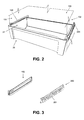
- the present invention relates to a movable compartment engagement system intended for household appliances, more specifically, refrigerators apparatus, defined by a cabinet 10 comprising left 131 and right 132 side walls and back 133 and lower 134 surfaces delimiting at least one inner compartment 11 capable of housing at least one movable compartment 20 (or drawer) as can be best viewed in the appended Figure 2 , 6.1 and 6.2 , which usually presents right 21 and left 22 side walls whose upper edges protrudes outward and downward, forming skirts 23.
- each upper edges of the side walls 21 and 22 of the movable compartment 20 comprises at least one substantially convex protrusion 24, while on the longitudinal surface of the skirt 23 of the movable compartment 20 is located a protrusion 25 that, in the presented exemplary embodiment, has a substantially triangular form having a substantially convex lower end 26.
- the system of the present invention comprises two sliding means 100 and 200 with constructive particularities aimed at minimizing and / or absorbing to the maximum the possibilities of horizontal and vertical displacement of the movable compartment 20 or drawer, as well as its diagonally displacement, so as to make a smoother sliding along the tracks and with little risk of suffering jamming or undue disengaging which may cause the fall of the compartment 20.
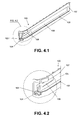
- the system presented herein comprises a track or slide means 100, represented in detail in appended Figures 4.1 and 4.2 , which, in the preferred embodiment presented herein, is preferably installed in a built-in manner in the left side wall 131 of the cabinet 10 with the aid of at least one engagement means 101 which may be a rod, pin or protrusion liable to be coupled to a snap or hole of the left side wall 131 of the cabinet 10 by snap, interference or snap-fit so that it is not necessary to use any engagement means or additional tool for installation of the slide means 100.
- engagement means 101 may be a rod, pin or protrusion liable to be coupled to a snap or hole of the left side wall 131 of the cabinet 10 by snap, interference or snap-fit so that it is not necessary to use any engagement means or additional tool for installation of the slide means 100.
- the slide means 100 has a lower inner channel 102 for sliding the substantially convex lower end 26 of the movable compartment 20, and an upper surface 107 with which the substantially convex protrusion 24 will remain in contact to prevent vertical displacement of the movable compartment 20, thereby facilitating its opening and closing during use.
- the front end of said lower inner channel 102 is provided with a semicircular protrusion 103 provided with a longitudinal slot 104 which has a width substantially coincident with the width of the lower end of the skirt 23 of the movable compartment 20, so as to provide a fitted engagement of the skirt 23 and prevent that in this inlet point - which is usually the most critical location for the occurrence of displacement that, in similar ones known in the current state of the art, entails a diagonally movement that significantly hinders the sliding of the drawer - there are clearances which allow the movable cabinet leaves the proper trajectory.
- This fitted snap can be seen in enlarged detail in attached Figure 7 .
- the system comprises a slide means 200 (shown in Figures 5.1 and 5.2 ) designed to be installed on the right side wall 132 of the inner compartment 11, which also comprises a lower inner channel 202 cooperating with the substantially convex lower end 26 of the movable compartment 20, and a upper surface 207 cooperating with the substantially convex protrusion 24 of the movable compartment 20, and the front end of said lower inner channel 202 has a semicircular protrusion 203 also provided with longitudinal slot 204, however in order to facilitate the engagement of the drawer, it is significantly wider than the width of the skirt 23 of the movable compartment 20.
- the sliding means 100 and 200 are provided, on the inner face of the side surfaces 105 and 205, with resilient elements 106, 206 which, after fastening the sliding means 100/200 to the side walls 131/132 of the cabinet 10, acquire convex surfaces form (see description of appended Figure 7.2 ) designed for the inner region of the sliding means 100, 200.
- the resilient elements 106 and 206 of the sliding means 100 and 200 exert forces in opposite directions against the skirts 23 of the movable compartment 20 so as to prevent horizontal displacement thereof and, consequently, always maintaining it in the suitable slide position.
- the resilient elements 106/206 can be made of the same material of the sliding means 100/200, or comprise separate elements of any resilient materials solidary with the side surfaces 105 and 205 without, therefore, departing from the scope of protection claimed herein.
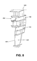
- the sliding means 100, 200 associated with a movable structure as that shown in attached Figures 8 to 10 , which comprise more specifically, a member 500, preferably in a vertical plate form, removably cooperating with the back 133 and lower 134 surfaces of the case 10. Therefore, the back and lower end of member 500 may be provided with any engagement means to removably cooperate with the back 133 and lower 134 surfaces of the cabinet 10 by snap, interference or snap-fit. It should be noted that this embodiment also aims at not using any kind of metallic component due to the reason already expressed above.
- said member 500 comprises left side surface 501 comprising one or more sliding means 200 cooperating with a movable compartment 20, and the left side surface 502 comprising one or more sliding means 100 cooperating with a movable compartment 20.
- both sides of the plate 500 are provided with tracks that allow the user to make different arrangements of drawers or movable compartments 20, thus providing the optimization of the available space and also the separation of the stored products according to its individual preferences.
- the member 500 in order to enable the practical use of the member 500 as a subdivisor element of the inner compartment 11, it can be provide for the possibility of installing additional members 500 along the sidewalls 131, 132 of the cabinet, or the possibility of engaging various sliding means 100, 200 on said side walls 131, 132 (see Figure 9 ) for a wide possibility of alternative arrangement for engaging the movable compartments 20.
- Figures 9 and 10 An example of this modularity is shown in Figures 9 and 10 , which disclose the use of three movable compartments 20 of different capacities in the inner compartment 11, and by removing member 500, the use of a single movable compartment is allowed.
- the object of the present invention solves the drawbacks of the prior art in an economical, practical and effective manner regarding the solution of the problem of making the engagement of sliding drawers safer and versatile in household refrigerators, besides of allowing the variation of configuration thereof in a certain storage space.
Landscapes
- Engineering & Computer Science (AREA)
- Chemical & Material Sciences (AREA)
- Combustion & Propulsion (AREA)
- Physics & Mathematics (AREA)
- Mechanical Engineering (AREA)
- Thermal Sciences (AREA)
- General Engineering & Computer Science (AREA)
- Drawers Of Furniture (AREA)
- Refrigerator Housings (AREA)
- Devices That Are Associated With Refrigeration Equipment (AREA)
Applications Claiming Priority (1)
| Application Number | Priority Date | Filing Date | Title |
|---|---|---|---|
| BR102014012397A BR102014012397A2 (pt) | 2014-05-22 | 2014-05-22 | sistema de acoplamento de compartimentos móveis para aparelhos eletrodomésticos, aparelho eletrodoméstico provido do referido sistema de acoplamento, e estrutura móvel compreendendo sistemas de acoplamento de compartimentos móveis para aparelhos eletrodomésticos |
Publications (3)
| Publication Number | Publication Date |
|---|---|
| EP2947407A2 true EP2947407A2 (de) | 2015-11-25 |
| EP2947407A3 EP2947407A3 (de) | 2016-02-17 |
| EP2947407B1 EP2947407B1 (de) | 2017-12-06 |
Family
ID=53488118
Family Applications (1)
| Application Number | Title | Priority Date | Filing Date |
|---|---|---|---|
| EP15168984.1A Not-in-force EP2947407B1 (de) | 2014-05-22 | 2015-05-22 | Bewegliches fach und bewegliches facheinrücksystem für haushaltsgeräte, haushaltsgerät mit diesem fach und mit diesem einrücksystem |
Country Status (2)
| Country | Link |
|---|---|
| EP (1) | EP2947407B1 (de) |
| BR (1) | BR102014012397A2 (de) |
Citations (7)
| Publication number | Priority date | Publication date | Assignee | Title |
|---|---|---|---|---|
| US5044704A (en) | 1990-05-17 | 1991-09-03 | Whirlpool Corporation | Adjustable refrigerator crisper drawer structure |
| US6945617B2 (en) | 2003-03-14 | 2005-09-20 | Illinois Tool Works, Inc. | Half-prong wedge for sliding drawers |
| WO2007007950A1 (en) | 2005-07-12 | 2007-01-18 | Lg Electronics Inc. | Rail assembly for drawer-type refrigerator |
| BRPI0504387A (pt) | 2005-09-19 | 2007-06-05 | Electrolux Do Brasil Sa | coluna interna multifuncional para refrigerador ou similar |
| KR20080029046A (ko) | 2006-09-28 | 2008-04-03 | 엘지전자 주식회사 | 냉장고 서랍 장착구조 |
| JP4254670B2 (ja) | 2004-09-08 | 2009-04-15 | パナソニック株式会社 | 冷蔵庫 |
| US20120262044A1 (en) | 2011-04-18 | 2012-10-18 | General Electric Company | Consumer appliance drawer with improved anti-racking system |
Family Cites Families (4)
| Publication number | Priority date | Publication date | Assignee | Title |
|---|---|---|---|---|
| US3087771A (en) * | 1960-10-19 | 1963-04-30 | Jack M Pari | Adjustable drawer and shelf slide mounting assembly |
| DE2603753C3 (de) * | 1976-01-31 | 1980-08-28 | Heino Schulz Kunststoffverarbeitung, 5300 Bonn | Vorrichtung zum Führen von aus Möbeln ausziehbaren Möbelteilen, wie Tisch- oder Schrankschubkästen |
| DE58906490D1 (de) * | 1988-10-28 | 1994-02-03 | Klinotec Med Tech | Schrankanordnung. |
| DE202006007332U1 (de) * | 2006-05-08 | 2006-07-13 | BSH Bosch und Siemens Hausgeräte GmbH | Kühlgutträger für ein Kältegerät |
-
2014
- 2014-05-22 BR BR102014012397A patent/BR102014012397A2/pt not_active IP Right Cessation
-
2015
- 2015-05-22 EP EP15168984.1A patent/EP2947407B1/de not_active Not-in-force
Patent Citations (7)
| Publication number | Priority date | Publication date | Assignee | Title |
|---|---|---|---|---|
| US5044704A (en) | 1990-05-17 | 1991-09-03 | Whirlpool Corporation | Adjustable refrigerator crisper drawer structure |
| US6945617B2 (en) | 2003-03-14 | 2005-09-20 | Illinois Tool Works, Inc. | Half-prong wedge for sliding drawers |
| JP4254670B2 (ja) | 2004-09-08 | 2009-04-15 | パナソニック株式会社 | 冷蔵庫 |
| WO2007007950A1 (en) | 2005-07-12 | 2007-01-18 | Lg Electronics Inc. | Rail assembly for drawer-type refrigerator |
| BRPI0504387A (pt) | 2005-09-19 | 2007-06-05 | Electrolux Do Brasil Sa | coluna interna multifuncional para refrigerador ou similar |
| KR20080029046A (ko) | 2006-09-28 | 2008-04-03 | 엘지전자 주식회사 | 냉장고 서랍 장착구조 |
| US20120262044A1 (en) | 2011-04-18 | 2012-10-18 | General Electric Company | Consumer appliance drawer with improved anti-racking system |
Also Published As
| Publication number | Publication date |
|---|---|
| EP2947407A3 (de) | 2016-02-17 |
| BR102014012397A2 (pt) | 2015-12-22 |
| EP2947407B1 (de) | 2017-12-06 |
Similar Documents
| Publication | Publication Date | Title |
|---|---|---|
| US8840205B2 (en) | Refrigerator appliance and a shelf assembly for the same | |
| US7594707B2 (en) | Snap-in bearing rack and pinion system | |
| US9982937B2 (en) | Appliance with geared drawer assembly | |
| US9677807B2 (en) | Refrigerator | |
| CN101568278B (zh) | 可伸缩的延伸装置 | |
| EP2292998B1 (de) | Kühlschrankschublade und Kühlschrank damit | |
| US9182168B2 (en) | Compartmentalized storage container | |
| US20130300276A1 (en) | Drawer assembly for a refrigerator appliance | |
| US20190075924A1 (en) | Adjustable shelving assembly for a refrigerator appliance | |
| US20120097147A1 (en) | Extension rack assembly for consumer appliance and consumer appliance incorporating same | |
| US20130257253A1 (en) | Crisper pan system for a domestic refrigerator | |
| US20130257254A1 (en) | Crisper pan guide system for a domestic refrigerator | |
| KR102120103B1 (ko) | 저장용기 및 이를 포함하는 냉장고 | |
| KR101299064B1 (ko) | 레일 고정 장치 | |
| US20160015176A1 (en) | Adjustable Shelf Support System for Medicine Cabinet | |
| WO2015171945A1 (en) | Drawer glide mechanism | |
| EP2947407B1 (de) | Bewegliches fach und bewegliches facheinrücksystem für haushaltsgeräte, haushaltsgerät mit diesem fach und mit diesem einrücksystem | |
| WO2008072868A1 (en) | Locking mechanism and slide having the same | |
| EP2235457A1 (de) | Kältegerät | |
| US10900706B2 (en) | Double-telescoping leg leveler | |
| US12193567B2 (en) | Drawer glide mechanism | |
| CN105157334A (zh) | 储物盒及具有该储物盒的冰箱 | |
| WO2014102120A1 (en) | Cooling appliance having a drawer guide | |
| EP3712544B1 (de) | Verkleidungsteil für kühlschrankregale | |
| CN114076488A (zh) | 具有以无滚轮固定支座支承的食品容纳壳的家用制冷器具 |
Legal Events
| Date | Code | Title | Description |
|---|---|---|---|
| PUAI | Public reference made under article 153(3) epc to a published international application that has entered the european phase |
Free format text: ORIGINAL CODE: 0009012 |
|
| AK | Designated contracting states |
Kind code of ref document: A2 Designated state(s): AL AT BE BG CH CY CZ DE DK EE ES FI FR GB GR HR HU IE IS IT LI LT LU LV MC MK MT NL NO PL PT RO RS SE SI SK SM TR |
|
| AX | Request for extension of the european patent |
Extension state: BA ME |
|
| PUAL | Search report despatched |
Free format text: ORIGINAL CODE: 0009013 |
|
| AK | Designated contracting states |
Kind code of ref document: A3 Designated state(s): AL AT BE BG CH CY CZ DE DK EE ES FI FR GB GR HR HU IE IS IT LI LT LU LV MC MK MT NL NO PL PT RO RS SE SI SK SM TR |
|
| AX | Request for extension of the european patent |
Extension state: BA ME |
|
| RIC1 | Information provided on ipc code assigned before grant |
Ipc: F25D 25/02 20060101AFI20160114BHEP Ipc: A47B 88/16 20060101ALN20160114BHEP |
|
| 17P | Request for examination filed |
Effective date: 20160810 |
|
| RBV | Designated contracting states (corrected) |
Designated state(s): AL AT BE BG CH CY CZ DE DK EE ES FI FR GB GR HR HU IE IS IT LI LT LU LV MC MK MT NL NO PL PT RO RS SE SI SK SM TR |
|
| GRAP | Despatch of communication of intention to grant a patent |
Free format text: ORIGINAL CODE: EPIDOSNIGR1 |
|
| RIC1 | Information provided on ipc code assigned before grant |
Ipc: F25D 25/02 20060101AFI20170523BHEP Ipc: A47B 88/57 20170101ALN20170523BHEP |
|
| INTG | Intention to grant announced |
Effective date: 20170616 |
|
| RIN1 | Information on inventor provided before grant (corrected) |
Inventor name: TRES, ANDREI Inventor name: IZUI, EDSON LUIS Inventor name: SCHULZE, MARCIO |
|
| GRAS | Grant fee paid |
Free format text: ORIGINAL CODE: EPIDOSNIGR3 |
|
| GRAA | (expected) grant |
Free format text: ORIGINAL CODE: 0009210 |
|
| AK | Designated contracting states |
Kind code of ref document: B1 Designated state(s): AL AT BE BG CH CY CZ DE DK EE ES FI FR GB GR HR HU IE IS IT LI LT LU LV MC MK MT NL NO PL PT RO RS SE SI SK SM TR |
|
| REG | Reference to a national code |
Ref country code: GB Ref legal event code: FG4D |
|
| REG | Reference to a national code |
Ref country code: AT Ref legal event code: REF Ref document number: 952753 Country of ref document: AT Kind code of ref document: T Effective date: 20171215 Ref country code: CH Ref legal event code: EP |
|
| REG | Reference to a national code |
Ref country code: IE Ref legal event code: FG4D |
|
| REG | Reference to a national code |
Ref country code: DE Ref legal event code: R096 Ref document number: 602015006429 Country of ref document: DE |
|
| REG | Reference to a national code |
Ref country code: NL Ref legal event code: MP Effective date: 20171206 |
|
| REG | Reference to a national code |
Ref country code: LT Ref legal event code: MG4D |
|
| PG25 | Lapsed in a contracting state [announced via postgrant information from national office to epo] |
Ref country code: FI Free format text: LAPSE BECAUSE OF FAILURE TO SUBMIT A TRANSLATION OF THE DESCRIPTION OR TO PAY THE FEE WITHIN THE PRESCRIBED TIME-LIMIT Effective date: 20171206 Ref country code: LT Free format text: LAPSE BECAUSE OF FAILURE TO SUBMIT A TRANSLATION OF THE DESCRIPTION OR TO PAY THE FEE WITHIN THE PRESCRIBED TIME-LIMIT Effective date: 20171206 Ref country code: NO Free format text: LAPSE BECAUSE OF FAILURE TO SUBMIT A TRANSLATION OF THE DESCRIPTION OR TO PAY THE FEE WITHIN THE PRESCRIBED TIME-LIMIT Effective date: 20180306 Ref country code: SE Free format text: LAPSE BECAUSE OF FAILURE TO SUBMIT A TRANSLATION OF THE DESCRIPTION OR TO PAY THE FEE WITHIN THE PRESCRIBED TIME-LIMIT Effective date: 20171206 Ref country code: ES Free format text: LAPSE BECAUSE OF FAILURE TO SUBMIT A TRANSLATION OF THE DESCRIPTION OR TO PAY THE FEE WITHIN THE PRESCRIBED TIME-LIMIT Effective date: 20171206 |
|
| REG | Reference to a national code |
Ref country code: AT Ref legal event code: MK05 Ref document number: 952753 Country of ref document: AT Kind code of ref document: T Effective date: 20171206 |
|
| REG | Reference to a national code |
Ref country code: FR Ref legal event code: PLFP Year of fee payment: 4 |
|
| PG25 | Lapsed in a contracting state [announced via postgrant information from national office to epo] |
Ref country code: LV Free format text: LAPSE BECAUSE OF FAILURE TO SUBMIT A TRANSLATION OF THE DESCRIPTION OR TO PAY THE FEE WITHIN THE PRESCRIBED TIME-LIMIT Effective date: 20171206 Ref country code: HR Free format text: LAPSE BECAUSE OF FAILURE TO SUBMIT A TRANSLATION OF THE DESCRIPTION OR TO PAY THE FEE WITHIN THE PRESCRIBED TIME-LIMIT Effective date: 20171206 Ref country code: RS Free format text: LAPSE BECAUSE OF FAILURE TO SUBMIT A TRANSLATION OF THE DESCRIPTION OR TO PAY THE FEE WITHIN THE PRESCRIBED TIME-LIMIT Effective date: 20171206 Ref country code: BG Free format text: LAPSE BECAUSE OF FAILURE TO SUBMIT A TRANSLATION OF THE DESCRIPTION OR TO PAY THE FEE WITHIN THE PRESCRIBED TIME-LIMIT Effective date: 20180306 |
|
| PG25 | Lapsed in a contracting state [announced via postgrant information from national office to epo] |
Ref country code: NL Free format text: LAPSE BECAUSE OF FAILURE TO SUBMIT A TRANSLATION OF THE DESCRIPTION OR TO PAY THE FEE WITHIN THE PRESCRIBED TIME-LIMIT Effective date: 20171206 |
|
| PG25 | Lapsed in a contracting state [announced via postgrant information from national office to epo] |
Ref country code: CZ Free format text: LAPSE BECAUSE OF FAILURE TO SUBMIT A TRANSLATION OF THE DESCRIPTION OR TO PAY THE FEE WITHIN THE PRESCRIBED TIME-LIMIT Effective date: 20171206 Ref country code: EE Free format text: LAPSE BECAUSE OF FAILURE TO SUBMIT A TRANSLATION OF THE DESCRIPTION OR TO PAY THE FEE WITHIN THE PRESCRIBED TIME-LIMIT Effective date: 20171206 Ref country code: SK Free format text: LAPSE BECAUSE OF FAILURE TO SUBMIT A TRANSLATION OF THE DESCRIPTION OR TO PAY THE FEE WITHIN THE PRESCRIBED TIME-LIMIT Effective date: 20171206 |
|
| PGFP | Annual fee paid to national office [announced via postgrant information from national office to epo] |
Ref country code: DE Payment date: 20180515 Year of fee payment: 4 |
|
| PG25 | Lapsed in a contracting state [announced via postgrant information from national office to epo] |
Ref country code: AT Free format text: LAPSE BECAUSE OF FAILURE TO SUBMIT A TRANSLATION OF THE DESCRIPTION OR TO PAY THE FEE WITHIN THE PRESCRIBED TIME-LIMIT Effective date: 20171206 Ref country code: RO Free format text: LAPSE BECAUSE OF FAILURE TO SUBMIT A TRANSLATION OF THE DESCRIPTION OR TO PAY THE FEE WITHIN THE PRESCRIBED TIME-LIMIT Effective date: 20171206 Ref country code: SM Free format text: LAPSE BECAUSE OF FAILURE TO SUBMIT A TRANSLATION OF THE DESCRIPTION OR TO PAY THE FEE WITHIN THE PRESCRIBED TIME-LIMIT Effective date: 20171206 Ref country code: PL Free format text: LAPSE BECAUSE OF FAILURE TO SUBMIT A TRANSLATION OF THE DESCRIPTION OR TO PAY THE FEE WITHIN THE PRESCRIBED TIME-LIMIT Effective date: 20171206 |
|
| PGFP | Annual fee paid to national office [announced via postgrant information from national office to epo] |
Ref country code: IT Payment date: 20180531 Year of fee payment: 4 Ref country code: FR Payment date: 20180529 Year of fee payment: 4 |
|
| REG | Reference to a national code |
Ref country code: DE Ref legal event code: R097 Ref document number: 602015006429 Country of ref document: DE |
|
| PLBE | No opposition filed within time limit |
Free format text: ORIGINAL CODE: 0009261 |
|
| STAA | Information on the status of an ep patent application or granted ep patent |
Free format text: STATUS: NO OPPOSITION FILED WITHIN TIME LIMIT |
|
| 26N | No opposition filed |
Effective date: 20180907 |
|
| PG25 | Lapsed in a contracting state [announced via postgrant information from national office to epo] |
Ref country code: DK Free format text: LAPSE BECAUSE OF FAILURE TO SUBMIT A TRANSLATION OF THE DESCRIPTION OR TO PAY THE FEE WITHIN THE PRESCRIBED TIME-LIMIT Effective date: 20171206 Ref country code: SI Free format text: LAPSE BECAUSE OF FAILURE TO SUBMIT A TRANSLATION OF THE DESCRIPTION OR TO PAY THE FEE WITHIN THE PRESCRIBED TIME-LIMIT Effective date: 20171206 |
|
| REG | Reference to a national code |
Ref country code: CH Ref legal event code: PL |
|
| REG | Reference to a national code |
Ref country code: BE Ref legal event code: MM Effective date: 20180531 |
|
| PG25 | Lapsed in a contracting state [announced via postgrant information from national office to epo] |
Ref country code: MC Free format text: LAPSE BECAUSE OF FAILURE TO SUBMIT A TRANSLATION OF THE DESCRIPTION OR TO PAY THE FEE WITHIN THE PRESCRIBED TIME-LIMIT Effective date: 20171206 |
|
| REG | Reference to a national code |
Ref country code: IE Ref legal event code: MM4A |
|
| PG25 | Lapsed in a contracting state [announced via postgrant information from national office to epo] |
Ref country code: CH Free format text: LAPSE BECAUSE OF NON-PAYMENT OF DUE FEES Effective date: 20180531 Ref country code: LI Free format text: LAPSE BECAUSE OF NON-PAYMENT OF DUE FEES Effective date: 20180531 |
|
| PG25 | Lapsed in a contracting state [announced via postgrant information from national office to epo] |
Ref country code: LU Free format text: LAPSE BECAUSE OF NON-PAYMENT OF DUE FEES Effective date: 20180522 |
|
| PG25 | Lapsed in a contracting state [announced via postgrant information from national office to epo] |
Ref country code: IE Free format text: LAPSE BECAUSE OF NON-PAYMENT OF DUE FEES Effective date: 20180522 |
|
| PG25 | Lapsed in a contracting state [announced via postgrant information from national office to epo] |
Ref country code: BE Free format text: LAPSE BECAUSE OF NON-PAYMENT OF DUE FEES Effective date: 20180531 |
|
| REG | Reference to a national code |
Ref country code: DE Ref legal event code: R119 Ref document number: 602015006429 Country of ref document: DE |
|
| GBPC | Gb: european patent ceased through non-payment of renewal fee |
Effective date: 20190522 |
|
| PG25 | Lapsed in a contracting state [announced via postgrant information from national office to epo] |
Ref country code: MT Free format text: LAPSE BECAUSE OF NON-PAYMENT OF DUE FEES Effective date: 20180522 |
|
| PG25 | Lapsed in a contracting state [announced via postgrant information from national office to epo] |
Ref country code: TR Free format text: LAPSE BECAUSE OF FAILURE TO SUBMIT A TRANSLATION OF THE DESCRIPTION OR TO PAY THE FEE WITHIN THE PRESCRIBED TIME-LIMIT Effective date: 20171206 |
|
| PG25 | Lapsed in a contracting state [announced via postgrant information from national office to epo] |
Ref country code: IT Free format text: LAPSE BECAUSE OF NON-PAYMENT OF DUE FEES Effective date: 20190522 Ref country code: GB Free format text: LAPSE BECAUSE OF NON-PAYMENT OF DUE FEES Effective date: 20190522 Ref country code: DE Free format text: LAPSE BECAUSE OF NON-PAYMENT OF DUE FEES Effective date: 20191203 |
|
| PG25 | Lapsed in a contracting state [announced via postgrant information from national office to epo] |
Ref country code: PT Free format text: LAPSE BECAUSE OF FAILURE TO SUBMIT A TRANSLATION OF THE DESCRIPTION OR TO PAY THE FEE WITHIN THE PRESCRIBED TIME-LIMIT Effective date: 20171206 |
|
| PG25 | Lapsed in a contracting state [announced via postgrant information from national office to epo] |
Ref country code: GR Free format text: LAPSE BECAUSE OF FAILURE TO SUBMIT A TRANSLATION OF THE DESCRIPTION OR TO PAY THE FEE WITHIN THE PRESCRIBED TIME-LIMIT Effective date: 20171206 Ref country code: MK Free format text: LAPSE BECAUSE OF NON-PAYMENT OF DUE FEES Effective date: 20171206 Ref country code: HU Free format text: LAPSE BECAUSE OF FAILURE TO SUBMIT A TRANSLATION OF THE DESCRIPTION OR TO PAY THE FEE WITHIN THE PRESCRIBED TIME-LIMIT; INVALID AB INITIO Effective date: 20150522 Ref country code: CY Free format text: LAPSE BECAUSE OF FAILURE TO SUBMIT A TRANSLATION OF THE DESCRIPTION OR TO PAY THE FEE WITHIN THE PRESCRIBED TIME-LIMIT Effective date: 20171206 Ref country code: FR Free format text: LAPSE BECAUSE OF NON-PAYMENT OF DUE FEES Effective date: 20190531 |
|
| PG25 | Lapsed in a contracting state [announced via postgrant information from national office to epo] |
Ref country code: AL Free format text: LAPSE BECAUSE OF FAILURE TO SUBMIT A TRANSLATION OF THE DESCRIPTION OR TO PAY THE FEE WITHIN THE PRESCRIBED TIME-LIMIT Effective date: 20171206 Ref country code: IS Free format text: LAPSE BECAUSE OF FAILURE TO SUBMIT A TRANSLATION OF THE DESCRIPTION OR TO PAY THE FEE WITHIN THE PRESCRIBED TIME-LIMIT Effective date: 20180406 |
|
| P01 | Opt-out of the competence of the unified patent court (upc) registered |
Effective date: 20230523 |