EP2947552A1 - Bedienungsvorrichtung - Google Patents
Bedienungsvorrichtung Download PDFInfo
- Publication number
- EP2947552A1 EP2947552A1 EP13872080.0A EP13872080A EP2947552A1 EP 2947552 A1 EP2947552 A1 EP 2947552A1 EP 13872080 A EP13872080 A EP 13872080A EP 2947552 A1 EP2947552 A1 EP 2947552A1
- Authority
- EP
- European Patent Office
- Prior art keywords
- image area
- touch
- operation surface
- touch operation
- finger
- Prior art date
- Legal status (The legal status is an assumption and is not a legal conclusion. Google has not performed a legal analysis and makes no representation as to the accuracy of the status listed.)
- Ceased
Links
Images






Classifications
-
- G—PHYSICS
- G06—COMPUTING OR CALCULATING; COUNTING
- G06F—ELECTRIC DIGITAL DATA PROCESSING
- G06F3/00—Input arrangements for transferring data to be processed into a form capable of being handled by the computer; Output arrangements for transferring data from processing unit to output unit, e.g. interface arrangements
- G06F3/01—Input arrangements or combined input and output arrangements for interaction between user and computer
- G06F3/048—Interaction techniques based on graphical user interfaces [GUI]
- G06F3/0484—Interaction techniques based on graphical user interfaces [GUI] for the control of specific functions or operations, e.g. selecting or manipulating an object, an image or a displayed text element, setting a parameter value or selecting a range
- G06F3/0485—Scrolling or panning
-
- B—PERFORMING OPERATIONS; TRANSPORTING
- B60—VEHICLES IN GENERAL
- B60K—ARRANGEMENT OR MOUNTING OF PROPULSION UNITS OR OF TRANSMISSIONS IN VEHICLES; ARRANGEMENT OR MOUNTING OF PLURAL DIVERSE PRIME-MOVERS IN VEHICLES; AUXILIARY DRIVES FOR VEHICLES; INSTRUMENTATION OR DASHBOARDS FOR VEHICLES; ARRANGEMENTS IN CONNECTION WITH COOLING, AIR INTAKE, GAS EXHAUST OR FUEL SUPPLY OF PROPULSION UNITS IN VEHICLES
- B60K35/00—Instruments specially adapted for vehicles; Arrangement of instruments in or on vehicles
- B60K35/10—Input arrangements, i.e. from user to vehicle, associated with vehicle functions or specially adapted therefor
-
- B—PERFORMING OPERATIONS; TRANSPORTING
- B60—VEHICLES IN GENERAL
- B60K—ARRANGEMENT OR MOUNTING OF PROPULSION UNITS OR OF TRANSMISSIONS IN VEHICLES; ARRANGEMENT OR MOUNTING OF PLURAL DIVERSE PRIME-MOVERS IN VEHICLES; AUXILIARY DRIVES FOR VEHICLES; INSTRUMENTATION OR DASHBOARDS FOR VEHICLES; ARRANGEMENTS IN CONNECTION WITH COOLING, AIR INTAKE, GAS EXHAUST OR FUEL SUPPLY OF PROPULSION UNITS IN VEHICLES
- B60K35/00—Instruments specially adapted for vehicles; Arrangement of instruments in or on vehicles
- B60K35/20—Output arrangements, i.e. from vehicle to user, associated with vehicle functions or specially adapted therefor
- B60K35/21—Output arrangements, i.e. from vehicle to user, associated with vehicle functions or specially adapted therefor using visual output, e.g. blinking lights or matrix displays
- B60K35/22—Display screens
-
- B—PERFORMING OPERATIONS; TRANSPORTING
- B60—VEHICLES IN GENERAL
- B60K—ARRANGEMENT OR MOUNTING OF PROPULSION UNITS OR OF TRANSMISSIONS IN VEHICLES; ARRANGEMENT OR MOUNTING OF PLURAL DIVERSE PRIME-MOVERS IN VEHICLES; AUXILIARY DRIVES FOR VEHICLES; INSTRUMENTATION OR DASHBOARDS FOR VEHICLES; ARRANGEMENTS IN CONNECTION WITH COOLING, AIR INTAKE, GAS EXHAUST OR FUEL SUPPLY OF PROPULSION UNITS IN VEHICLES
- B60K35/00—Instruments specially adapted for vehicles; Arrangement of instruments in or on vehicles
- B60K35/20—Output arrangements, i.e. from vehicle to user, associated with vehicle functions or specially adapted therefor
- B60K35/21—Output arrangements, i.e. from vehicle to user, associated with vehicle functions or specially adapted therefor using visual output, e.g. blinking lights or matrix displays
- B60K35/23—Head-up displays [HUD]
-
- B—PERFORMING OPERATIONS; TRANSPORTING
- B60—VEHICLES IN GENERAL
- B60K—ARRANGEMENT OR MOUNTING OF PROPULSION UNITS OR OF TRANSMISSIONS IN VEHICLES; ARRANGEMENT OR MOUNTING OF PLURAL DIVERSE PRIME-MOVERS IN VEHICLES; AUXILIARY DRIVES FOR VEHICLES; INSTRUMENTATION OR DASHBOARDS FOR VEHICLES; ARRANGEMENTS IN CONNECTION WITH COOLING, AIR INTAKE, GAS EXHAUST OR FUEL SUPPLY OF PROPULSION UNITS IN VEHICLES
- B60K35/00—Instruments specially adapted for vehicles; Arrangement of instruments in or on vehicles
- B60K35/20—Output arrangements, i.e. from vehicle to user, associated with vehicle functions or specially adapted therefor
- B60K35/29—Instruments characterised by the way in which information is handled, e.g. showing information on plural displays or prioritising information according to driving conditions
-
- B—PERFORMING OPERATIONS; TRANSPORTING
- B60—VEHICLES IN GENERAL
- B60K—ARRANGEMENT OR MOUNTING OF PROPULSION UNITS OR OF TRANSMISSIONS IN VEHICLES; ARRANGEMENT OR MOUNTING OF PLURAL DIVERSE PRIME-MOVERS IN VEHICLES; AUXILIARY DRIVES FOR VEHICLES; INSTRUMENTATION OR DASHBOARDS FOR VEHICLES; ARRANGEMENTS IN CONNECTION WITH COOLING, AIR INTAKE, GAS EXHAUST OR FUEL SUPPLY OF PROPULSION UNITS IN VEHICLES
- B60K35/00—Instruments specially adapted for vehicles; Arrangement of instruments in or on vehicles
- B60K35/50—Instruments characterised by their means of attachment to or integration in the vehicle
-
- B—PERFORMING OPERATIONS; TRANSPORTING
- B60—VEHICLES IN GENERAL
- B60K—ARRANGEMENT OR MOUNTING OF PROPULSION UNITS OR OF TRANSMISSIONS IN VEHICLES; ARRANGEMENT OR MOUNTING OF PLURAL DIVERSE PRIME-MOVERS IN VEHICLES; AUXILIARY DRIVES FOR VEHICLES; INSTRUMENTATION OR DASHBOARDS FOR VEHICLES; ARRANGEMENTS IN CONNECTION WITH COOLING, AIR INTAKE, GAS EXHAUST OR FUEL SUPPLY OF PROPULSION UNITS IN VEHICLES
- B60K35/00—Instruments specially adapted for vehicles; Arrangement of instruments in or on vehicles
- B60K35/60—Instruments characterised by their location or relative disposition in or on vehicles
-
- B—PERFORMING OPERATIONS; TRANSPORTING
- B60—VEHICLES IN GENERAL
- B60K—ARRANGEMENT OR MOUNTING OF PROPULSION UNITS OR OF TRANSMISSIONS IN VEHICLES; ARRANGEMENT OR MOUNTING OF PLURAL DIVERSE PRIME-MOVERS IN VEHICLES; AUXILIARY DRIVES FOR VEHICLES; INSTRUMENTATION OR DASHBOARDS FOR VEHICLES; ARRANGEMENTS IN CONNECTION WITH COOLING, AIR INTAKE, GAS EXHAUST OR FUEL SUPPLY OF PROPULSION UNITS IN VEHICLES
- B60K35/00—Instruments specially adapted for vehicles; Arrangement of instruments in or on vehicles
- B60K35/80—Arrangements for controlling instruments
-
- B—PERFORMING OPERATIONS; TRANSPORTING
- B60—VEHICLES IN GENERAL
- B60K—ARRANGEMENT OR MOUNTING OF PROPULSION UNITS OR OF TRANSMISSIONS IN VEHICLES; ARRANGEMENT OR MOUNTING OF PLURAL DIVERSE PRIME-MOVERS IN VEHICLES; AUXILIARY DRIVES FOR VEHICLES; INSTRUMENTATION OR DASHBOARDS FOR VEHICLES; ARRANGEMENTS IN CONNECTION WITH COOLING, AIR INTAKE, GAS EXHAUST OR FUEL SUPPLY OF PROPULSION UNITS IN VEHICLES
- B60K35/00—Instruments specially adapted for vehicles; Arrangement of instruments in or on vehicles
- B60K35/80—Arrangements for controlling instruments
- B60K35/81—Arrangements for controlling instruments for controlling displays
-
- B—PERFORMING OPERATIONS; TRANSPORTING
- B60—VEHICLES IN GENERAL
- B60K—ARRANGEMENT OR MOUNTING OF PROPULSION UNITS OR OF TRANSMISSIONS IN VEHICLES; ARRANGEMENT OR MOUNTING OF PLURAL DIVERSE PRIME-MOVERS IN VEHICLES; AUXILIARY DRIVES FOR VEHICLES; INSTRUMENTATION OR DASHBOARDS FOR VEHICLES; ARRANGEMENTS IN CONNECTION WITH COOLING, AIR INTAKE, GAS EXHAUST OR FUEL SUPPLY OF PROPULSION UNITS IN VEHICLES
- B60K35/00—Instruments specially adapted for vehicles; Arrangement of instruments in or on vehicles
- B60K35/90—Calibration of instruments, e.g. setting initial or reference parameters; Testing of instruments, e.g. detecting malfunction
-
- G—PHYSICS
- G06—COMPUTING OR CALCULATING; COUNTING
- G06F—ELECTRIC DIGITAL DATA PROCESSING
- G06F3/00—Input arrangements for transferring data to be processed into a form capable of being handled by the computer; Output arrangements for transferring data from processing unit to output unit, e.g. interface arrangements
- G06F3/01—Input arrangements or combined input and output arrangements for interaction between user and computer
- G06F3/03—Arrangements for converting the position or the displacement of a member into a coded form
- G06F3/033—Pointing devices displaced or positioned by the user, e.g. mice, trackballs, pens or joysticks; Accessories therefor
- G06F3/0354—Pointing devices displaced or positioned by the user, e.g. mice, trackballs, pens or joysticks; Accessories therefor with detection of two-dimensional [2D] relative movements between the device, or an operating part thereof, and a plane or surface, e.g. 2D mice, trackballs, pens or pucks
- G06F3/03547—Touch pads, in which fingers can move on a surface
-
- G—PHYSICS
- G06—COMPUTING OR CALCULATING; COUNTING
- G06F—ELECTRIC DIGITAL DATA PROCESSING
- G06F3/00—Input arrangements for transferring data to be processed into a form capable of being handled by the computer; Output arrangements for transferring data from processing unit to output unit, e.g. interface arrangements
- G06F3/01—Input arrangements or combined input and output arrangements for interaction between user and computer
- G06F3/048—Interaction techniques based on graphical user interfaces [GUI]
- G06F3/0481—Interaction techniques based on graphical user interfaces [GUI] based on specific properties of the displayed interaction object or a metaphor-based environment, e.g. interaction with desktop elements like windows or icons, or assisted by a cursor's changing behaviour or appearance
- G06F3/0482—Interaction with lists of selectable items, e.g. menus
-
- G—PHYSICS
- G06—COMPUTING OR CALCULATING; COUNTING
- G06F—ELECTRIC DIGITAL DATA PROCESSING
- G06F3/00—Input arrangements for transferring data to be processed into a form capable of being handled by the computer; Output arrangements for transferring data from processing unit to output unit, e.g. interface arrangements
- G06F3/01—Input arrangements or combined input and output arrangements for interaction between user and computer
- G06F3/048—Interaction techniques based on graphical user interfaces [GUI]
- G06F3/0487—Interaction techniques based on graphical user interfaces [GUI] using specific features provided by the input device, e.g. functions controlled by the rotation of a mouse with dual sensing arrangements, or of the nature of the input device, e.g. tap gestures based on pressure sensed by a digitiser
- G06F3/0488—Interaction techniques based on graphical user interfaces [GUI] using specific features provided by the input device, e.g. functions controlled by the rotation of a mouse with dual sensing arrangements, or of the nature of the input device, e.g. tap gestures based on pressure sensed by a digitiser using a touch-screen or digitiser, e.g. input of commands through traced gestures
-
- B—PERFORMING OPERATIONS; TRANSPORTING
- B60—VEHICLES IN GENERAL
- B60K—ARRANGEMENT OR MOUNTING OF PROPULSION UNITS OR OF TRANSMISSIONS IN VEHICLES; ARRANGEMENT OR MOUNTING OF PLURAL DIVERSE PRIME-MOVERS IN VEHICLES; AUXILIARY DRIVES FOR VEHICLES; INSTRUMENTATION OR DASHBOARDS FOR VEHICLES; ARRANGEMENTS IN CONNECTION WITH COOLING, AIR INTAKE, GAS EXHAUST OR FUEL SUPPLY OF PROPULSION UNITS IN VEHICLES
- B60K2360/00—Indexing scheme associated with groups B60K35/00 or B60K37/00 relating to details of instruments or dashboards
- B60K2360/143—Touch sensitive instrument input devices
- B60K2360/1438—Touch screens
- B60K2360/1442—Emulation of input devices
-
- B—PERFORMING OPERATIONS; TRANSPORTING
- B60—VEHICLES IN GENERAL
- B60K—ARRANGEMENT OR MOUNTING OF PROPULSION UNITS OR OF TRANSMISSIONS IN VEHICLES; ARRANGEMENT OR MOUNTING OF PLURAL DIVERSE PRIME-MOVERS IN VEHICLES; AUXILIARY DRIVES FOR VEHICLES; INSTRUMENTATION OR DASHBOARDS FOR VEHICLES; ARRANGEMENTS IN CONNECTION WITH COOLING, AIR INTAKE, GAS EXHAUST OR FUEL SUPPLY OF PROPULSION UNITS IN VEHICLES
- B60K2360/00—Indexing scheme associated with groups B60K35/00 or B60K37/00 relating to details of instruments or dashboards
- B60K2360/146—Instrument input by gesture
-
- B—PERFORMING OPERATIONS; TRANSPORTING
- B60—VEHICLES IN GENERAL
- B60K—ARRANGEMENT OR MOUNTING OF PROPULSION UNITS OR OF TRANSMISSIONS IN VEHICLES; ARRANGEMENT OR MOUNTING OF PLURAL DIVERSE PRIME-MOVERS IN VEHICLES; AUXILIARY DRIVES FOR VEHICLES; INSTRUMENTATION OR DASHBOARDS FOR VEHICLES; ARRANGEMENTS IN CONNECTION WITH COOLING, AIR INTAKE, GAS EXHAUST OR FUEL SUPPLY OF PROPULSION UNITS IN VEHICLES
- B60K2360/00—Indexing scheme associated with groups B60K35/00 or B60K37/00 relating to details of instruments or dashboards
- B60K2360/18—Information management
- B60K2360/182—Distributing information between displays
-
- B—PERFORMING OPERATIONS; TRANSPORTING
- B60—VEHICLES IN GENERAL
- B60K—ARRANGEMENT OR MOUNTING OF PROPULSION UNITS OR OF TRANSMISSIONS IN VEHICLES; ARRANGEMENT OR MOUNTING OF PLURAL DIVERSE PRIME-MOVERS IN VEHICLES; AUXILIARY DRIVES FOR VEHICLES; INSTRUMENTATION OR DASHBOARDS FOR VEHICLES; ARRANGEMENTS IN CONNECTION WITH COOLING, AIR INTAKE, GAS EXHAUST OR FUEL SUPPLY OF PROPULSION UNITS IN VEHICLES
- B60K2360/00—Indexing scheme associated with groups B60K35/00 or B60K37/00 relating to details of instruments or dashboards
- B60K2360/55—Remote control arrangements
-
- B—PERFORMING OPERATIONS; TRANSPORTING
- B60—VEHICLES IN GENERAL
- B60K—ARRANGEMENT OR MOUNTING OF PROPULSION UNITS OR OF TRANSMISSIONS IN VEHICLES; ARRANGEMENT OR MOUNTING OF PLURAL DIVERSE PRIME-MOVERS IN VEHICLES; AUXILIARY DRIVES FOR VEHICLES; INSTRUMENTATION OR DASHBOARDS FOR VEHICLES; ARRANGEMENTS IN CONNECTION WITH COOLING, AIR INTAKE, GAS EXHAUST OR FUEL SUPPLY OF PROPULSION UNITS IN VEHICLES
- B60K35/00—Instruments specially adapted for vehicles; Arrangement of instruments in or on vehicles
- B60K35/20—Output arrangements, i.e. from vehicle to user, associated with vehicle functions or specially adapted therefor
- B60K35/26—Output arrangements, i.e. from vehicle to user, associated with vehicle functions or specially adapted therefor using acoustic output
Definitions
- the disclosure is related to an operation apparatus.
- a touch sensing type input apparatus including a touch panel is known in which a selection target item in an operation image area displayed on a display is selected with a selection operation on the touch panel to implement an input operation of the selection target item (see Patent Document 1, for example).
- Patent Document 1 Japanese Laid-open Patent Publication No. 2006-029917
- a user in order to scroll a list in the operation image area, a user has to perform, at first, a selection operation for selecting a selection target item used for scrolling in the operation image area, and then perform an enter operation for the selection target item for scrolling.
- a plurality of operations are required, resulting in a lack of convenience.
- Such problems hold true not only for the list scroll operation, but also for other scroll operations, page turning operation, etc.
- an object of the disclosure is to provide an operation apparatus with which scroll operations, etc., becomes easier with space saving being implemented.
- an operation apparatus which includes:
- an operation apparatus which makes scroll operations, etc., easier while implementing space saving.
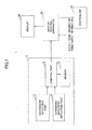
- Fig. 1 is a diagram for schematically illustrating a system configuration of an operation apparatus for vehicle 1 according to an embodiment.
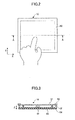
- Fig. 2 is a plan view for schematically illustrating a touch pad 10.
- Fig. 3 is a cross-sectional view for schematically illustrating a cross section of a main part of the touch pad 10. It is noted that, in Fig. 2 , a hand operating a coordinate detection part 12 (touch operation surface) of the touch pad 10 is schematically illustrated; however, it is not illustrated in Fig. 3 .
- Fig. 4 is a diagram for schematically illustrating an example of an operation image area displayed on a display 20.
- Fig. 5 is a diagram for schematically illustrating the display 20 and the touch pad 10 and for conceptually illustrating an example of an operation in an absolute coordination mode.
- the operation apparatus for vehicle 1 includes the touch pad 10, the display 20, and a display control apparatus 30.
- the touch pad 10 is provided at an appropriate place in a cabin.
- the touch pad 10 is provided at a place where a driver can easily operate it (the driver can extend a hand to reach it with a driving posture being kept).
- the touch pad 10 is typically disposed at a place where an operator can extend his/her hand from a nearer side of the touch pad 10 to operate the touch pad 10.
- the touch pad 10 may be disposed at or around a console box, for example.
- the touch pad 10 includes the coordinate detection part 12, a downward movement detection part 14, a control part 16 and a memory 18.
- the touch pad 10 includes the outer frame element 50, a stopper 52, an elastic element 54, and a substrate 60, as illustrated in Fig. 2 .
- the coordinate detection part 12 includes a substantially planer two-dimensional operation surface (touch operation surface) on a top side thereof, illustrated in Fig. 2 .
- An electrostatic capacitance type sensor is provided in the touch operation surface.
- the output signal of the electrostatic capacitance type sensor is transmitted to the control part 16.
- the coordinate detection part 12 is formed by an electrostatic capacitance type pad, for example.
- the electrostatic capacitance type pad has such a construction that electrodes (i.e., the electrostatic capacitance type sensor) extend linearly in x and y directions in a plane with insulation bodies being sandwiched therebetween, for example.
- a condenser When a finger of a human comes close to the electrodes via an insulating panel, a condenser is formed with the electrode and the plate formed of the finger and an electrical charge amount (and thus electrostatic capacitance) of the electrode is changed.
- detection signals of the electrodes i.e., a signal representing a change amount of the charge accumulated in the electrode
- the coordinate detection part 12 is configured such that the coordinate detection part 12 can move in up and down directions (Z direction illustrated in Fig. 3 ).
- a mechanism for enabling the coordinate detection part 12 to move in the up and down direction may be arbitrary.
- the coordinate detection part 12 is supported by the substrate 60 via the elastic element 54.
- the stroke of the up and down movements of the coordinate detection part 12 may be arbitrary and may be slight.
- the outer frame element 50 is provided at an outer region of the coordinate detection part 12.
- the outer frame element 50 is provided such that the outer frame element 50 protrudes upward with respect to the touch operation surface of the coordinate detection part 12, as illustrated in Fig. 3 .
- the outer frame element 50 protrudes upward with respect to a surface surrounding the touch pad 10 (i.e., the surface of the console box around the touch pad 10, if the touch pad 10 is provided in the console box, for example).
- the outer frame element 50 may be attached to the coordinate detection part 12 such that the outer frame element 50 is integrated with the coordinate detection part 12.
- the outer frame element 50 may be coupled to the outer region of the coordinate detection part 12 by means of fit, an adhesive, or a fastener such as a screw, etc.
- the outer frame element 50 may be attached such that the outer frame element 50 is provided on the touch operation surface (i.e., the outer frame element 50 covers the outer region of the touch operation surface), or the outer frame element 50 may be attached to a side portion (side surface) of the outer region of the touch operation surface such that the outer frame element 50 does not cover the outer region of the touch operation surface.
- the outer frame element 50 may be formed of an arbitrary material, and may be formed of a material that is different from that of the coordinate detection part 12. Further, the outer frame element 50 may be formed integrally and simultaneously with the coordinate detection part 12. It is noted that the outer frame element 50 is configured such that the outer frame element 50 can move in the up and down directions together with the coordinate detection part 12, because the touch pad 10 is provided integrally with the coordinate detection part 12.
- the stopper 52 restricts the stroke of the up and down movements of the outer frame element 50 and the coordinate detection part 12.
- the stopper 52 is provided below the outer frame element 50.
- the stopper 52 may be provided below the coordinate detection part 12.
- the outer frame element 50 and the coordinate detection part 12 restrict the down movement by the stopper 52 abutting the upper surface of the substrate 60.
- the stopper mechanism can be varied, and other stopper mechanisms may be used.
- another stopper mechanism for restricting the up movement of the outer frame element 50 and the coordinate detection part 12 may be added.
- a guide mechanism for guiding the up and down movements of the outer frame element 50 and the coordinate detection part 12 may be added.
- a mechanism for generating a click feeling (or a vibration) upon the outer frame element 50 and the coordinate detection part 12 moving in the down direction more than a predetermined amount may be added.
- the elastic element 54 may be formed by an arbitrary spring such as a plate spring, a coil spring, etc., or may be formed of a rubber or a soft resin.
- the elastic element 54 presses the coordinate detection part 12 in the up direction such that the coordinate detection part 12 is kept at its nominal height.
- the downward movement detection part 14 outputs a signal representing the down movement of the outer frame element 50 and the coordinate detection part 12 of the touch pad 10.
- the downward movement detection part 14 may be formed by a tact switch, a pressure sensing sensor (piezoelectric elements), etc.
- the downward movement detection part 14 may be disposed at any place as long as the down movement of the operation surface of the coordinate detection part 12 causes the downward movement detection part 14 to come in contact with the coordinate detection part 12 or the outer frame element 50.
- the pressure sensing sensor forming the downward movement detection part 14 is provided below a center portion of the coordinate detection part 12; however, the pressure sensing sensor may be provided around the coordinate detection part 12 (i.e., below the outer frame element 50). Further, a plurality of the pressure sensing sensors forming the downward movement detection part 14 may be provided at different places.
- the control part 16 and the memory 18 are formed by a microcomputer, for example.
- the control part 16 and the memory 18 may be installed on the substrate 60.
- the respective functions of the control part 16 may be implemented by any hardware, any software, any firmware or any combination thereof.
- any part of or all the functions of the processing device 16 may be implemented by an ASIC (application-specific integrated circuit), a FPGA (Field Programmable Gate Array) or a DSP (digital signal processor).
- the functions of the control part 16 may be implemented by a plurality of computers in cooperation.
- the control part 16 detects, based on an output (output signal) from the electrostatic capacitance type sensor of the coordinate detection part 12, a touch of a finger on the touch operation surface. At that time, the control part 16 generates a coordinate signal representing coordinates of a position in the touch operation surface, that is to say, the coordinates of the position (contact position of the operating finger) at which the touch operation is performed by the operator. It is noted that, in the case where the coordinate detection part 12 is formed by the electrostatic capacitance type pad, the charge of the condenser formed by the operating finger is accumulated as described above, and the change amounts of the charges at the respective electrodes differ according to the position of the operating finger.
- the position of the operating finger can be identified based on the detection signals from the respective electrodes.
- the control part 16 detects the touch of the finger on the touch operation surface and generates the coordinate signal based on the position of the electrode whose level of the detection signal is maximum (local maximum).
- the predetermined reference value may be related to a change amount of the charge accumulated in the electrode, for example.
- the control part 16 determines that the selection operation is performed by the operator to generate the coordinate signal (representing the two-dimensional position at which the change amount of the charge is maximum), while the control part 16 determines that there is no contact of the finger with the touch operation surface and does not generate the coordinate signal when the change amount of the charge accumulated in any electrodes does not exceed the reference value.
- the reference value may be stored in the memory 18. The coordinate signal thus generated is transmitted to the display control apparatus 30.
- the control part 16 generates an enter signal based on an output signal from the downward movement detection part 14. For example, in the case where the downward movement detection part 14 is formed by the pressure sensing sensor, the control part 16 generates the enter signal when an output (pressing down pressure) from the pressure sensing sensor exceeds a predetermined threshold Pn. In the case where the downward movement detection part 14 is formed by the tact switch, the control part 16 generates the enter signal when an ON signal is input from the tact switch. The enter signal thus generated is transmitted to the display control apparatus 30. It is noted that, in the case where a plurality of the pressure sensing sensors forming the downward movement detection part 14 are provided, the control part 16 may generate the enter signal when the output from any one of the pressure sensing sensors exceeds a predetermined threshold Pn.
- the pressure sensing sensors are provided not for the sake of detecting the pressed down location on the touch pad 10 (typically, the electrostatic capacitance type pad forming the coordinate detection part 12) but for the sake of determining whether the pressing down operation on the touch pad 10 is performed.
- the enter signal represents only the occurrence of an event that the outer frame element 50 and the coordinate detection part 12 move in the down direction, and may not include other information such as information about the position of the pressed down location (information representing which of the outer frame element 50 and the coordinate detection part 12 is pressed down).
- the control part 16 may the enter signal when the ON signal from any one of the tact switches is input. The enter signal thus generated is transmitted to the display control apparatus 30.
- the outer frame element 50 is provided.
- the enter signal is transmitted with the coordinate signal being transmitted
- the enter signal is transmitted without the coordinate signal being transmitted.
- the enter signal and the coordinate signal are generated; however, only the enter signal is generated and the coordinate signal is not generated when the operator presses down only the outer frame element 50 with his/her finger to cause it to move in the down direction without touching the touch pad 10 (i.e., without the detection threshold for the touch of the finger being exceeded).
- the control part 16 communicates with the display control apparatus 30 to transmit various items of information (the coordinate signal, the enter signal, a message output demand, etc.) to the display control apparatus 30. It is noted that a part or all of the functions of the control part 16 may be implemented by the coordinate detection part 12.
- the display 20 is disposed remotely with respect to the touch pad 10.
- the display 20 may be an arbitrary display device such as a liquid crystal display and a HUD (Head-Up Display).
- the display 20 may be placed at an appropriate location in the vehicle (in an instrument panel, for example).
- the display 20 may be of a touch panel type or of a type for which the touch operation cannot be performed.
- An operation image area (see Fig. 4 ) representing an operation content that can be operated with the touch pad 10 is displayed on the display 20. It is noted that, at a background of the operation image area, or during the time the operation image area is not being displayed, an image of a TV, a surrounding circumstance monitoring camera, etc., may be displayed on the display 20.
- the operation image area may be displayed over an overall image area as illustrated in Fig. 4 , or may be displayed at a part of the overall image area.
- the operation image area may include two or more selection target items that can be operated with the touch pad 10, as illustrated in Fig. 4 .
- the operation image area may include other information display portions (a portion for displaying a TV, a state of an audio apparatus, an outside temperature, travel information such as gas mileage, entertainment information, etc.). It is noted that, in the example illustrated in Fig. 4 , the operation image area is used for the various operations for a radio with the touch pad 10.
- the selection target items form imaginary operation buttons (which means that the selection target items are not buttons of mechanical type that are directly operated by the hand).
- the selection target items (operation buttons) may be related to any types (functions).
- the contents operable with the touch pad 10 may be arbitrary.
- the selection target items may be operated for requesting (calling) an image area for various settings for a navigation apparatus or a map image area (including a display of the current position, for example) to be displayed on the display 20.
- the selection target items may be operated for various settings for an air conditioner, or for requesting its operation image area to be displayed on the display 20.
- the selection target items may be operated for various settings (a volume adjustment, etc.) for an audio apparatus or a TV, or for requesting its operation image area to be displayed on the display 20.
- the selection target items may include icons, launchers, etc., for starting up any application.
- the selection target items may include text input buttons in the operation image area such as an operation image area for inputting the Japanese syllabary, etc.
- the selection target items may include respective lists 71a through 71f to be scrolled in a list display area 90 (i.e., a list image area), as illustrated in Fig. 4 .
- the number of the lists 71a through 71f, the contents thereof, the display manner thereof, etc., may be arbitrary.
- a way of scrolling the lists may be arbitrary.
- the lists may be scrolled in an endless manner as if the lists were on a drum (a rotating body), or may be scrolled such that scrolling is stopped at the ends thereof.
- the lists 71a through 71f are selection target items for setting a frequency for the radio and represents the respective frequencies that can be set.
- the selection target items may include a button for scrolling 72 that is to be operated for scrolling the lists.
- the button for scrolling 72 includes a button 72a for the list scroll in the upward direction and a button 72b for the list scroll in the downward direction.
- States of the selection target items each are changed from an ordinary displayed state to a selected state or from the selected state to the ordinary displayed state based on the coordinate signal from the touch pad 10 under the control of the display control apparatus 30 as described hereinafter.
- a cursor 80 that can be moved with the operations on the touch pad 10 is displayed on the display 20.
- the cursor 80 is on the selection target item "SAT" related to satellite broadcasting, for example, and thus the selection target item "SAT" is displayed in the selected state.
- the cursor 80 herein represents the selection target item itself that is displayed in the selected state.
- the position of the cursor 80 corresponds to the position of the selection target item displayed in the selected state.
- the display control apparatus 30 is formed by a microcomputer, for example, and may be embodied as an ECU. It is noted that a connection manner between the display control apparatus 30 and the touch pad 10 is arbitrary, including a wired connection, a wireless connection or a combination thereof, and the display control apparatus 30 and the touch pad 10 may be connected directly or indirectly. Further, a part or all of the functions of the display control apparatus 30 may be implemented by the control part 16 of the touch pad 10 or a control part (not illustrated) of the display 20. Conversely, a part or all of the functions of the control part 16 of the touch pad 10 may be implemented by the display control apparatus 30.
- Vehicle speed information representing vehicle speed, power source information related to a state (IG, ACC) of an electric power source of the vehicle, etc., may be input to the display control apparatus 30, if necessary.
- the display control apparatus 30 is connected to a controller 40.
- the controller 40 controls devices to be operated with the operation apparatus for vehicle 1.
- the controller 40 may include an audio controller that controls the audio apparatus, a navigation controller that controls the navigation apparatus, a controller that controls the air conditioner, etc.
- the display control apparatus 30 may implement a part or all of the functions of the controller 40.
- the display control apparatus 30 coordinates the display 20 with the touch pad 10 to assist the operations on the touch pad 10. Specifically, the display control apparatus 30 causes the display 20 to display the operation image area (see Fig. 4 ), and performs a selection process, an enter process, etc., of the selection target items based on the signals (the coordinate signal and the enter signal) from the touch pad 10.
- the display control apparatus 30 when the display control apparatus 30 receives the coordinate signal from the touch pad 10 as described above, the display control apparatus 30 causes one of the selection target items in the operation image area to be displayed in the selected state (i.e., the display control apparatus 30 responds to "a selection operation". In other words, the display control apparatus 30 determines the position of the cursor 80. At that time, the display control apparatus 30 may operate in an absolute coordinate mode. According to the absolute coordinate mode, a coordinate system of the image area of the display 20 corresponds to a coordinate system of the operation surface of the touch pad 10 in a fixed manner.
- the coordinate system of the image area of the display 20 is associated with the coordinate system of the operation surface of the touch pad 10 in such a fixed manner that an original point of the coordinate system of the image area of the display 20 is located at a fixed position and an original point of the coordinate system of the operation surface of the touch pad 10 is located at a fixed position.
- the coordinate system of the image area of the display 20 in which the original point thereof is fixed at a left and bottom corner of the image area of the display 20 is associated with the coordinate system of the operation surface of the touch pad 10 in which the original point thereof is fixed at a left and bottom corner of the operation surface of the touch pad 10.
- a size of the overall image area of the display 20 is not equal to a size of the operation surface of the touch pad 10, and thus the relationship between the respective coordinate systems may be proportional according to the ratio of the size therebetween.
- any one of the selection target items may be displayed in the selected state as a default, or none may be displayed in the selected state.
- a way of implementing the selected state i.e., the image of the cursor 80
- the selected state may be implemented by making luminance, color, etc., of the selection target item to be displayed in the selected state different from that of other selection target items, or featuring a boundary of the selection target item to be displayed in the selected state with respect to that of other selection target items.
- the display control apparatus 30 may keep the selection target item being displayed in the selected state even if the coordinate signal from the touch pad 10 is not input afterward. This is because there is a probability that, even after the finger has been away from the touch pad 10, the continuation of the operation may be performed.
- the selected state of the selection target item may be maintained until another selection target item is selected in response to the coordinate signal from the touch pad 10 afterward (or until the image area is switched to another image area, or the image area is turned off).
- the selected state of the selection target item may be maintained until a relatively long period lapses after no coordinate signal is input from the touch pad 10.
- the display control apparatus 30 when the display control apparatus 30 receives the enter signal from the touch pad 10, the display control apparatus 30 implements the operation content of the selection target item displayed in the selected state at that time (i.e., the display control apparatus 30 implements an enter function in response to "an enter operation").
- the operation content depends on the selection target item related to the enter operation, and may involve a transition of the image area such as displaying a hierarchically lower selection target items, changing the operation image area, etc., inputting the text, launching the application, transmitting the control signal to the controller 40, etc.
- the display of the selection target item entered may be changed appropriately or a predetermined sound may be generated so as to inform the user of the acceptance of the "enter operation".
- the outer frame element 50 since the outer frame element 50 is provided, there are two cases, that is to say, a first case where the enter signal from the touch pad 10 is received with the reception of the coordinate signal from the touch pad 10, and a second case where only the enter signal from the touch pad 10 is received without the reception of the coordinate signal from the touch pad 10.
- a first case where the enter signal from the touch pad 10 is received with the reception of the coordinate signal from the touch pad 10
- second case where only the enter signal from the touch pad 10 is received without the reception of the coordinate signal from the touch pad 10.
- the display control apparatus 30 may respond to the enter operation described above.
- the display control apparatus 30 may not respond to the enter operation described above but implement functions described hereinafter.
- the display control apparatus 30 receives the enter signal from the touch pad 10 without the reception of the coordinate signal, there may be two cases, that is to say, a first case where the display control apparatus 30 responds to the enter operation described above under a predetermined condition, and a second case where the display control apparatus 30 does not respond to the enter operation described above but implement functions described hereinafter.
- the display control apparatus 30 may implement a predetermined function (different from the enter function) according to the operation image area that is currently displayed. For example, if the selection target items in the currently displayed operation image area include the lists to be scrolled, the display control apparatus 30 may implement the list scroll (i.e., a list scroll function), regardless of the presence or absence of the cursor 80 (i.e., the display control apparatus 30 responds to "a list scroll operation").
- a predetermined function different from the enter function
- the display control apparatus 30 may scroll the map image area itself (i.e., the display control apparatus 30 responds to "a map scroll operation"). Further, in the case of a plurality of pages of the operation image areas (the operation image areas with a hierarchical structure, for example), the display control apparatus 30 may successively change the page of the operation image area (i.e., a list scroll function), regardless of the presence or absence of the cursor 80 (i.e., the display control apparatus 30 responds to "an image area changing (page turning) operation").
- the display control apparatus 30 may successively change the page image area of the book (i.e., the display control apparatus 30 responds to "an image area changing (page turning) operation"). Further, in the case of the operation image areas for displaying WEB sites, for example, the display control apparatus 30 may successively change the image area such as so-called Back (Return)/Forward functions (i.e., the display control apparatus 30 responds to "an image area changing operation”). Further, the display control apparatus 30 may successively move the cursor 80 from the selection target item to another selection target item in the operation image area according to a predetermined rule (i.e., the display control apparatus 30 responds to "a cursor successively moving operation").
- a predetermined rule i.e., the display control apparatus 30 responds to "a cursor successively moving operation
- This successive movement of the cursor 80 may be implemented in only the currently displayed operation image area, or may involve change of the operation image area. It is noted that these functions may be continuously implemented during the reception of the enter signal from the touch pad 10 without the reception of the coordinate signal (i.e., during the time the outer frame element 50 is being pressed down).
- the display control apparatus 30 stops scrolling, etc., when the reception of the enter signal from the touch pad 10 is terminated.
- the display control apparatus 30 selectively responds to the enter operation or implements another function upon the display control apparatus 30 receiving the enter signal from the touch pad 10 without the reception of the coordinate signal.
- the enter function may be implemented by the operation pressing down only the outer frame element 50.
- such a configuration is also referred to as "a configuration in which the enter operation with the outer frame element 50 is possible”.
- the display control apparatus 30 when the display control apparatus 30 receives the enter signal from the touch pad 10 without the reception of the coordinate signal, the display control apparatus 30 scrolls the lists in the operation image area (i.e., the display control apparatus 30 responds to "the list scroll operation") upon a predetermined list scroll condition being met.
- the predetermined list scroll condition may include a condition where the selection target items of the currently displayed operation image area include lists, for example.
- the predetermined list scroll condition may include a condition where the selection target items of the currently displayed operation image area include lists and the cursor 80 is located in the list display area 90 (see Fig. 4 ), for example.
- the predetermined list scroll condition may include a condition where the selection target items of the currently displayed operation image area include lists and the cursor 80 is not on any selection target item or there is no cursor 80 displayed, for example.
- the list display area 90 may be an area that does not include the button for scrolling 72.
- the display control apparatus 30 may implement the function of the selection target item in the selected state (i.e., respond to the enter operation).
- the display control apparatus 30 when the display control apparatus 30 receives the enter signal from the touch pad 10 without the reception of the coordinate signal, the display control apparatus 30 scrolls the map image area itself (i.e., the display control apparatus 30 responds to the "map scroll operation") upon a predetermined map scroll condition being met.
- the predetermined map scroll condition may include a condition where the currently displayed operation image area includes the map image area, for example.
- the predetermined list scroll condition may include a condition where the currently displayed operation image area includes the map image area and there is no cursor 80 or pointer displayed on the map image area. In the latter case, the display control apparatus 30 may respond to the enter operation when the cursor 80 or the pointer is located on the map image area under a situation where the predetermined map scroll condition is not met.
- the display control apparatus 30 when the display control apparatus 30 receives the enter signal from the touch pad 10 without the reception of the coordinate signal, the display control apparatus 30 changes the image area (i.e., the display control apparatus 30 responds to the "image area changing operation") upon a predetermined image area changing condition being met.
- Changing the image area includes changing the operation image area and changing the WEB image area, as described above.
- the predetermined image area changing condition may include a condition where the cursor 80 or the pointer is not displayed, for example.
- the display control apparatus 30 may respond to the enter operation when the cursor 80 or the pointer is located on the image area under a condition where the predetermined image area changing condition is not met.
- the display control apparatus 30 when the display control apparatus 30 receives the enter signal from the touch pad 10 without the reception of the coordinate signal, the display control apparatus 30 implements the successive movement of the cursor 80 (i.e., the display control apparatus 30 responds to the cursor successively moving operation") upon a predetermined cursor successive movement condition being met.
- the predetermined cursor successive movement condition may include a condition where the cursor 80 is not displayed, for example.
- the display control apparatus 30 may implement the function of the selection target item in the selected state (i.e., respond to the enter operation).
- scrolling the lists may be implemented. Further, in the case of the configuration in which the enter operation with the outer frame element 50 is not possible, scrolling the lists may be implemented with higher priority over the image area changing operation and the cursor successively moving operation, for example.
- Fig. 6 is a diagram for explaining an example of a way of determining the scroll direction at the time of scrolling lists.
- Fig. 6 illustrates an example of the operation image area.
- the list display area 90 is imaginarily divided into an upper list display area 92 and a lower list display area 94.
- the display control apparatus 30 scrolls the lists if the cursor 80 is located in the list display area 90, for example.
- the display control apparatus 30 may scroll the lists in an upward direction when the cursor 80 is located in the upper list display area 92, while display control apparatus 30 may scroll the lists in a downward direction when the cursor 80 is located in the lower list display area 94. It is noted that, in the example illustrated in Fig. 6 , since the cursor 80 is located in the upper list display area 92, the lists are scrolled in the upward direction when the outer frame element 50 is pressed down.
- the operator may operate on the touch operation surface to move the cursor 80 to the upper list display area 92, at first, and then press down the outer frame element 50. It is noted that the operator who desires to scroll the lists in the list display area 90 in the upward direction, the operator may also operate on the touch operation surface to move the cursor 80 to a button for an upward scroll 72a, at first, and then press down the touch operation surface. However, in this case, since the button for an upward scroll 72a is smaller than the upper list display area 92, the operation for moving the cursor 80 is relatively difficult. It is noted that, in the embodiment, as described above, since the scroll operation with the outer frame element 50 is possible, the button for scrolling 72 can be omitted.
- the display control apparatus 30 may determine, according to the position of the cursor 80 in the operation image area, the scroll direction at the time of scrolling the lists. For example, the display control apparatus 30 may scroll the lists in the upward direction in response to the reception of the enter signal without the reception of the coordinate signal when the cursor 80 is located in the upper half of the operation image area, while the display control apparatus 30 may scroll the lists in the downward direction in response to the reception of the enter signal without the reception of the coordinate signal when the cursor 80 is located in the lower half of the operation image area.
- the list display area is imaginarily divided into left and right portions, and the scroll direction may be determined according to whether the cursor 80 is located in the left portion or the right portion.
- the display control apparatus 50 may scroll the lists in the leftward direction in response to the reception of the enter signal without the reception of the coordinate signal when the cursor 80 is located in the left half of the operation image area, while the display control apparatus 30 may scroll the lists in the rightward direction in response to the reception of the enter signal without the reception of the coordinate signal when the cursor 80 is located in the right half of the operation image area.
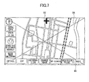
- Fig. 7 is a diagram for explaining an example of a way of determining the scroll direction at the time of scrolling a map.
- Fig. 7 illustrates an example of the operation image area including the map image area.
- the operation image area is imaginarily divided into four areas (an upper area, a lower area, a right area, and left area) by two imaginary lines 84 and 86 that extend toward the corners of the image area and intersect at the center of the image area.
- the display control apparatus 30 when the display control apparatus 30 receives the enter signal from the touch pad 10 without the reception of the coordinate signal, the display control apparatus 30 scrolls the map if the pointer 82 is located in the map image area and the cursor 80 is not displayed, for example.
- the display control apparatus 30 may scroll the map image area in the upward direction when the pointer 82 is located in the upper area, scroll the map image area in the downward direction when the pointer 82 is located in the lower area, scroll the map image area in the rightward direction when the pointer 82 is located in the right area, and scroll the map image area in the leftward direction when the pointer 82 is located in the left area. It is noted that, even in the configuration in which the enter operation with the outer frame element 50 is not possible, the display control apparatus 30 may determine, according to the position of the pointer 82 in the operation image area, the scroll direction at the time of scrolling the map. Thus, for the operator who desires to scroll the map image area in the upward direction, the operator may operate on the touch operation surface to move the pointer 82 to the upper area, at first, and then press down the outer frame element 50.
- the overall operation image area is imaginarily divided into the four areas; however, only the map image area in the operation image area may be imaginarily divided into the four areas. Further, the imaginary lines 84 and 86 may be displayed during the movement of the pointer 82.
- Fig. 8 is an example of a flowchart of a process executed by the display control apparatus 30.
- the configuration in which the enter operation with the outer frame element 50 is not possible is assumed.
- step S800 it is determined whether the enter signal is received from the touch pad 10. If it is determined that the enter signal is received from the touch pad 10, the process routine goes to step S802, otherwise ends directly.
- step S802 it is determined whether the coordinate signal is received from the touch pad 10. If it is determined that the coordinate signal is not received from the touch pad 10, the process routine goes to step S804. On the other hand, if it is determined that the coordinate signal is received from the touch pad 10, the process ends directly. It is noted that, in this case, another process routine is performed such that the selection process in response to the selection operation is performed based on the received coordinate signal.
- step S804 it is determined whether the currently displayed operation image area includes the list display area 90. If it is determined that the currently displayed operation image area includes the list display area 90, the process routine goes to step S806, otherwise the process routine goes to step S808.
- step S806 the lists in the list display area 90 are scrolled according to the position of the cursor 80.
- the display control apparatus 30 may scroll the lists in the upward direction when the cursor 80 is located in the upper half of the operation image area, while the display control apparatus 30 may scroll the lists in the downward direction when the cursor 80 is located in the lower half of the operation image area.
- This scroll process may be continuously performed during the reception of the enter signal. It is noted that the way of displaying the cursor 80 during the time the lists are being scrolled may be arbitrary.
- such a configuration may be used in which the cursor 80 may not move during the time the lists are being scrolled (only the lists are scrolled), or the cursor 80 may move to an uppermost or lowermost position according to the scroll direction during the lists being scrolled (only the lists are scrolled after the cursor 80 reaches the uppermost or lowermost position).
- step S808 it is determined whether the currently displayed image area is a map image area. It is noted that the map image area may include the selection target items therearound, as illustrated in Fig. 7 . If it is determined that the currently displayed image area is a map image area, the process routine goes to step S810. On the other hand, if it is determined that the currently displayed image area is not a map image area, the process routine ends directly. It is noted, in this case, the image area changing operation or the cursor successively moving operation may be implemented according to the currently displayed image area.
- step S810 the map image area is scrolled according to the position of the pointer 82 in the map image area.
- the display control apparatus 30 may scroll the map image area in the upward direction when the pointer 82 is located in the upper area of the map image area, scroll the map image area in the downward direction when the pointer 82 is located in the lower area of the map image area, scroll the map image area in the rightward direction when the pointer 82 is located in the right area of the map image area, and scroll the map image area in the leftward direction when the pointer 82 is located in the left area of the map image area.
- This scroll process may be continuously performed during the reception of the enter signal.
- Fig. 9 is a diagram for explaining another example of the way of determining the scroll direction at the time of scrolling the lists.
- Fig. 9 is a plane view that schematically illustrates a state of the hand operating on the touch operation surface.
- Fig. 10 is a diagram for schematically illustrating an image of the output level of the electrostatic capacitance type sensor at the time of the operation illustrated in Fig. 9 .
- a lateral axis indicates the position of the touch operation surface in Y direction
- a vertical axis indicates the output level of the electrostatic capacitance type sensor.
- two curves P10 and P20 are illustrated.
- Fig. 9 the state of the hand in operating on a farther side portion of the outer frame element 50 that corresponds to the farther side of the touch operation surface is schematically illustrated by a reference symbol P1
- the state of the hand in operating on a nearer side portion of the outer frame element 50 that corresponds to the nearer side of the touch operation surface is schematically illustrated by a reference symbol P2.
- the overall hand covers the touch operation surface when the pressing down operation on the farther side portion of the outer frame element 50 is performed, while the hand is not located above the touch operation surface when the pressing down operation on the nearer side portion of the outer frame element 50 is performed.
- such a difference causes the difference in the output level of the electrostatic capacitance type sensor, such a difference can be utilized to determine on which side of the outer frame element 50 the operation is performed.
- a wave shape P10 of the output level of the electrostatic capacitance type sensor when the pressing down operation on the farther side of the touch operation surface is performed is illustrated, and a wave shape P20 of the output level of the electrostatic capacitance type sensor when the pressing down operation on the nearer side of the touch operation surface is performed is illustrated.
- the pressing down operation is performed on the nearer side of the outer frame element 50 when the output level of the electrostatic capacitance type sensor is less than a setting value Th, while it can be determined that the pressing down operation is performed on the farther side of the outer frame element 50 when the output level of the electrostatic capacitance type sensor is greater than or equal to the setting value Th and less than a detection threshold related to the touch of the finger.
- the setting value Th may be adapted, based on experiment data of the output signal of the electrostatic capacitance type sensor obtained when the pressing down operation is performed on the nearer side of the outer frame element 50 and the experiment data obtained when the pressing down operation is performed on the farther side of the outer frame element 50, such that these two operations can be distinguished.
- Fig. 11 is another example of a flowchart of a process executed by a display control apparatus 30. The process illustrated in Fig. 11 may be performed instead of the process described above and illustrated in Fig. 8 .
- step S1100 it is determined whether the enter signal is received from the touch pad 10. If it is determined that the enter signal is received from the touch pad 10, the process routine goes to step S1102, otherwise ends directly.
- step S1102 it is determined whether the coordinate signal is received from the touch pad 10. If it is determined that the coordinate signal is not received from the touch pad 10, the process routine goes to step S1104. On the other hand, if it is determined that the coordinate signal is received from the touch pad 10, the process ends directly. It is noted that, in this case, another process routine is performed such that the selection process in response to the selection operation is performed based on the received coordinate signal.
- step S1104 it is determined whether the output level of the electrostatic capacitance type sensor is greater than or equal to the setting value Th (see Fig. 10 ). If it is determined that the output level of the electrostatic capacitance type sensor is greater than or equal to the setting value Th, the process routine goes to step S1106, otherwise the process routine goes to step S1108. It is noted that whether the output level of the electrostatic capacitance type sensor is greater than or equal to the setting value Th may be determined by the control part 16, and information representing the determination result thereof may be transmitted to the display control apparatus 30.
- the enter signal may have a plurality of types. Specifically, there are a first enter signal that is generated together with the coordinate signal, and a second enter signal that is generated without the generation of the coordinate signal.
- the second enter signal includes a first signal generated in the case where the output level of the electrostatic capacitance type sensor is greater than or equal to the setting value Th and less than the detection threshold related to the touch of the finger, and a second signal generated in the case where the output level of the electrostatic capacitance type sensor is less than the setting value Th.
- the process routine may go to step S1106, and if the display control apparatus 30 receives the second signal, the process routine may go to step S1108.
- the controller 15 performs the scroll process in the upward direction.
- the target to be scrolled may differ according to the currently displayed image area.
- the currently displayed image area is the operation image area including the list display area 90
- the lists in the list display area 90 may be scrolled in the upward direction.
- the map image area may be scrolled in the upward direction.
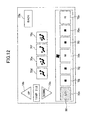
- the cursor 80 may be moved successively in the upward direction. For example, in the example illustrated in Fig.
- the cursor 80 may be moved successively from one of the selection target items 70a through 70n to another in alphabetic order toward letter "a" added after the numeral "70". Specifically, the cursor 80 that is currently on the selection target item 70h may be moved successively to the selection target items 70g, 70f, 70e, 70d, 70c, 70b and 70a in this order. It is noted that when the cursor 80 is moved to the selection target item 70a, the cursor 80 may be stopped, or moved to the selection target item 70n and further moved successively and upwardly again. Alternatively, if the currently displayed image area is a WEB image area, the WEB image (page) may be changed successively in a "Back" direction.
- the controller 15 performs the scroll process in the downward direction.
- the target to be scrolled may differ according to the currently displayed image area.
- the currently displayed image area is the operation image area including the list display area 90
- the lists in the list display area 90 may be scrolled in the downward direction.
- the map image area may be scrolled in the downward direction.
- the cursor 80 may be moved successively in the downward direction. For example, in the example illustrated in Fig.
- the cursor 80 may be moved successively from one of the selection target items 70a through 70n to another in alphabetic order toward letter "n" added after the numeral "70". Specifically, the cursor 80 that is currently on the selection target item 70h may be moved successively to the selection target items 70i, 70j, 70e, 70k, 70k, 70n and 70n in this order. It is noted that when the cursor 80 is moved to the selection target item 70n, the cursor 80 may be stopped, or moved to the selection target item 70a and further moved successively and downwardly again. Alternatively, if the currently displayed image area is the WEB image area, the WEB image (page) may be changed successively in a "Forward" direction.
- the pressing down operation on the nearer side portion of the outer frame element 50 and the pressing down operation on the farther side portion of the outer frame element 50 are distinguished and the scroll direction is varied according to the distinction result; however, in addition to or instead of it, the pressing down operation on the left side portion of the outer frame element 50 and the pressing down operation on the right side portion of the outer frame element 50 may be distinguished and the scroll direction may be varied according to the distinction result.
- the scroll process in the leftward direction may be performed upon the pressing down operation on the left side portion of the outer frame element 50
- the scroll process in the rightward direction may be performed upon the pressing down operation on the right side portion of the outer frame element 50.
- the successive movement of the cursor 80 in the leftward direction may be performed upon the pressing down operation on the left side portion of the outer frame element 50
- the successive movement of the cursor 80 in the rightward direction may be performed upon the pressing down operation on the right side portion of the outer frame element 50.
- successive change of the WEB image area in the "Back” direction may be performed upon the pressing down operation on the left side portion of the outer frame element 50
- the successive change of the WEB image area in the "Forward” direction may be performed upon the pressing down operation on the right side portion of the outer frame element 50.
- Fig. 13 is a diagram for schematically illustrating an example of a state of a hand at the time of the pressing down operation on the right side portion of the outer frame element 50, and an example of a state of the hand at the time of the pressing down operation on a left side portion of the outer frame element 50.
- Fig. 13 the state of the hand in operating on the right side portion of the outer frame element 50 that corresponds to the right side of the touch operation surface is schematically illustrated by a reference symbol P3, and the state of the hand in operating on the left side portion of the outer frame element 50 that corresponds to the left side of the touch operation surface is schematically illustrated by a reference symbol P4.
- the overall hand covers the right side region of the touch operation surface when the pressing down operation on the right side portion of the outer frame element 50 is performed, while the hand covers the left side region of the touch operation surface when the pressing down operation on the left side portion of the outer frame element 50 is performed.
- such a difference can be utilized to determine which side (left or right side) of the outer frame element 50 the operation is performed. For example, it can be determined that the pressing down operation is performed on the right side of the outer frame element 50 when the output level of the electrostatic capacitance type sensor in the right side region of the touch operation surface is greater than or equal to a setting value Th1 and less than the detection threshold related to the touch of the finger, while it can be determined that the pressing down operation is performed on the left side of the outer frame element 50 when the output level of the electrostatic capacitance type sensor in the left side region of the touch operation surface is greater than or equal to the setting value Th1 and less than a detection threshold related to the touch of the finger.
- the setting value Th1 may be adapted, based on experiment data of the output signal of the electrostatic capacitance type sensor obtained when the pressing down operation is performed on the right side of the outer frame element 50 and the experiment data obtained when the pressing down operation is performed on the left side of the outer frame element 50, such that these two operations can be distinguished.
- the outer frame element 50 is provided on the touch operation surface of the coordinate detection part 12, which enables distinguishing the pressing down operation on the touch operation surface from the pressing down operation on the outer frame element 50 based on the presence or absence of the coordinate signal at the time of the enter signal being generated.
- the different functions can be implemented, based on the distinction result, between the cases of the pressing down operation on the touch operation surface and the pressing down operation on the outer frame element 50, which enables saving the space while increasing the operability.
- the enter operation is implemented at the time of the pressing down operation on the touch operation surface, while the list scroll, etc., can be implemented at the time of the pressing down operation on the outer frame element 50.
- the mechanical switch for the scroll operation may be provided separately.
- the operation apparatus for vehicle 1 it becomes possible to omit the button for scrolling 72 in the operation image area, which enables saving the space in the operation image area.
- the button for scrolling 72 in the operation image area may be maintained.
- Fig. 14 is a diagram for illustrating an example of a touch pad 110 in a vehicle installed state according to another embodiment.
- Fig. 15 is a cross-sectional view for schematically illustrating a cross section along line C-C in Fig. 14 . It is noted that, in Fig. 15 , only a coordinate detection part 12 (touch operation surface) of the touch pad 110 is illustrated.
- the touch pad 110 is provided near a console box 8; however, the touch pad 110 may be provided at any place.
- the touch pad 110 differs from the touch pad 10 according to the examples described above in that the touch pad 110 does not include the outer frame element 50. Instead of it, the touch pad 110 has a dead zone 120 at the outer region of the coordinate detection part 12 (touch operation surface), as illustrated in Fig. 15 .
- the dead zone 120 is a region where the touch of the finger thereon does not cause the output signal of the electrostatic capacitance type sensor to be generated or the output signal is invalidated even if it is generated.
- the dead zone 120 may be implemented by not providing the electrodes therein. It is noted that a width W4 of the dead zone 120 on the nearer side of the touch operation surface may be equal to a width W5 of the dead zone 120 on other three sides.
- the touch operation surface of the coordinate detection part 12 is set higher than the surface surrounding the touch pad 110.
- the touch operation surface of the coordinate detection part 12 is set higher than the surface of the console box 8 around the touch pad 110. With this arrangement, the operability of the pressing down operation while touching only the dead zone 120 of the touch pad 110 is increased.
- the touch operation surface of the coordinate detection part 12 may be coplanar with the surface surrounding the touch pad 110, or may be lower than the surface surrounding the touch pad 110.
- the dead zone 120 is provided on the touch operation surface of the coordinate detection part 12, which enables distinguishing the pressing down operation on an effective zone (where the touch of the finger thereon causes the coordinate signal to be generated) of the touch operation surface from the pressing down operation on the dead zone 120 of the touch operation surface based on the presence or absence of the coordinate signal at the time of the enter signal being generated.
- the different functions can be implemented, based on the distinction result, between the cases of the pressing down operation on the effective zone of the touch operation surface and the pressing down operation on the dead zone 120 of the touch operation surface, which enables space saving while increasing the operability.
- the enter operation is implemented at the time of the pressing down operation on the effective zone of the touch operation surface, while the list scroll, etc., can be implemented at the time of the pressing down operation on the dead zone 120 of the touch operation surface.
- the mechanical switch for the scroll operation may be provided separately.
- the button for scrolling 72 in the operation image area may be maintained.
- the embodiments described above are related to the operation apparatus for vehicle 1; however, they are applicable to various operation apparatuses used not for the vehicle (operation apparatuses for ships, machines such as robots, etc.).
- the electrostatic capacitance type sensor is used in the mechanism for detecting the touch operation on the touch pad 10; however, other principles (sensors) may be used to detect the touch operation.
- the touch pad 10 may be formed of a touch panel of an surface acoustic wave type.
- the position of the cursor 80 is determined in the absolute coordinate mode; however, the position of the cursor 80 may be determined in a relative coordinate mode.
- the coordinate system of the image area of the display 20 corresponds to the coordinate system of the operation surface of the touch pad 10 in a relatively synchronized manner.
- the coordinate system of the image area of the display 20 is associated with the coordinate system of the operation surface of the touch pad 10 in such a manner that the original point of the coordinate system of the image area of the display 20 is located at the current position of the cursor 80 and the original point of the coordinate system of the operation surface of the touch pad 10 is located at the current touch position of the finger on the operation surface.
- the position of the cursor 80 is determined in the absolute coordinate mode; however, the absolute coordinate mode and the relative coordinate mode may be switched if necessary.
- the relative coordinate mode may be implemented when any one of the selection target items in the operation image area on the display 20 is selected (i.e., in the selected state), while the absolute coordinate mode may be implemented when any one of the selection target items in the operation image area on the display 20 is not selected (i.e., the cursor 80 is note displayed).
- the cursor 80 is used to indicate the relationship between the touch position of the finger of the user on the touch operation surface of the touch pad 10 and the position of the image area on the display 20; however, such a pointer used in an ordinary PC (personal computer), etc., may be used. Even if the pointer is used, the cursor 80 (identifying the selected state) may be maintained.
Landscapes
- Engineering & Computer Science (AREA)
- General Engineering & Computer Science (AREA)
- Theoretical Computer Science (AREA)
- Chemical & Material Sciences (AREA)
- Combustion & Propulsion (AREA)
- Transportation (AREA)
- Mechanical Engineering (AREA)
- Human Computer Interaction (AREA)
- Physics & Mathematics (AREA)
- General Physics & Mathematics (AREA)
- Position Input By Displaying (AREA)
- User Interface Of Digital Computer (AREA)
Applications Claiming Priority (1)
| Application Number | Priority Date | Filing Date | Title |
|---|---|---|---|
| PCT/JP2013/050847 WO2014112080A1 (ja) | 2013-01-17 | 2013-01-17 | 操作装置 |
Publications (2)
| Publication Number | Publication Date |
|---|---|
| EP2947552A1 true EP2947552A1 (de) | 2015-11-25 |
| EP2947552A4 EP2947552A4 (de) | 2016-01-13 |
Family
ID=51209201
Family Applications (1)
| Application Number | Title | Priority Date | Filing Date |
|---|---|---|---|
| EP13872080.0A Ceased EP2947552A4 (de) | 2013-01-17 | 2013-01-17 | Bedienungsvorrichtung |
Country Status (6)
| Country | Link |
|---|---|
| US (1) | US10061504B2 (de) |
| EP (1) | EP2947552A4 (de) |
| JP (1) | JP5962776B2 (de) |
| CN (1) | CN104919403B (de) |
| BR (1) | BR112015016792A2 (de) |
| WO (1) | WO2014112080A1 (de) |
Families Citing this family (11)
| Publication number | Priority date | Publication date | Assignee | Title |
|---|---|---|---|---|
| CN105320327A (zh) * | 2014-07-25 | 2016-02-10 | 南京瀚宇彩欣科技有限责任公司 | 手持式电子装置及其触控外盖 |
| US9727231B2 (en) | 2014-11-19 | 2017-08-08 | Honda Motor Co., Ltd. | System and method for providing absolute coordinate and zone mapping between a touchpad and a display screen |
| US20170371515A1 (en) | 2014-11-19 | 2017-12-28 | Honda Motor Co., Ltd. | System and method for providing absolute and zone coordinate mapping with graphic animations |
| JP6087394B2 (ja) * | 2015-06-17 | 2017-03-01 | 日本写真印刷株式会社 | 表示一体型入力装置 |
| DE102016003072A1 (de) * | 2016-03-12 | 2017-09-14 | Audi Ag | Bedienvorrichtung und Verfahren zum Erfassen einer Benutzerauswahl zumindest einer Bedienfuktion der Bedienvorrichtung |
| CN106873955A (zh) * | 2016-06-07 | 2017-06-20 | 阿里巴巴集团控股有限公司 | 动态列表的显示方法、装置、设备和系统 |
| DE102016216543A1 (de) * | 2016-09-01 | 2018-03-01 | Audi Ag | Bedieneinrichtung für ein Komfortsystem eines Kraftfahrzeugs, Komfortsystem mit einer Bedieneinrichtung und Kraftfahrzeug mit einem Komfortsystem |
| US10936163B2 (en) * | 2018-07-17 | 2021-03-02 | Methodical Mind, Llc. | Graphical user interface system |
| JP7112345B2 (ja) * | 2019-02-01 | 2022-08-03 | 本田技研工業株式会社 | 表示装置 |
| JP7337574B2 (ja) * | 2019-07-12 | 2023-09-04 | アルパイン株式会社 | 入力検出装置および入力検出方法 |
| JP7471998B2 (ja) * | 2020-11-05 | 2024-04-22 | 株式会社東海理化電機製作所 | 操作装置 |
Family Cites Families (22)
| Publication number | Priority date | Publication date | Assignee | Title |
|---|---|---|---|---|
| JPH10198507A (ja) | 1997-01-13 | 1998-07-31 | Komota Kk | ポインティングデバイス |
| US6496122B2 (en) * | 1998-06-26 | 2002-12-17 | Sharp Laboratories Of America, Inc. | Image display and remote control system capable of displaying two distinct images |
| US7469381B2 (en) * | 2007-01-07 | 2008-12-23 | Apple Inc. | List scrolling and document translation, scaling, and rotation on a touch-screen display |
| JP4161814B2 (ja) | 2003-06-16 | 2008-10-08 | ソニー株式会社 | 入力方法および入力装置 |
| JP4410625B2 (ja) | 2004-07-14 | 2010-02-03 | 株式会社東海理化電機製作所 | タッチ式入力装置 |
| CN100530065C (zh) * | 2006-04-20 | 2009-08-19 | 铼宝科技股份有限公司 | 透明触控面板结构 |
| US20080088600A1 (en) * | 2006-10-11 | 2008-04-17 | Apple Inc. | Method and apparatus for implementing multiple push buttons in a user input device |
| JP4366393B2 (ja) * | 2006-11-06 | 2009-11-18 | アルプス電気株式会社 | 入力装置 |
| US20090128507A1 (en) | 2007-09-27 | 2009-05-21 | Takeshi Hoshino | Display method of information display device |
| US8441450B2 (en) * | 2008-09-30 | 2013-05-14 | Apple Inc. | Movable track pad with added functionality |
| JP4670970B2 (ja) | 2009-01-28 | 2011-04-13 | ソニー株式会社 | 表示入力装置 |
| JP2010191892A (ja) * | 2009-02-20 | 2010-09-02 | Sony Corp | 情報処理装置、表示制御方法、及びプログラム |
| US20100275122A1 (en) * | 2009-04-27 | 2010-10-28 | Microsoft Corporation | Click-through controller for mobile interaction |
| CN101882018A (zh) * | 2009-05-06 | 2010-11-10 | 怡利电子工业股份有限公司 | 具有按键功能鼠标板的操作方法 |
| JP2011053974A (ja) | 2009-09-02 | 2011-03-17 | Sony Corp | 操作制御装置、操作制御方法およびコンピュータプログラム |
| WO2011139346A2 (en) * | 2010-04-30 | 2011-11-10 | Thomson Licensing | Primary screen view control through kinetic ui framework |
| US8527900B2 (en) * | 2010-07-21 | 2013-09-03 | Volkswagen Ag | Motor vehicle |
| TWI425391B (zh) * | 2010-07-28 | 2014-02-01 | Asustek Comp Inc | 活動式操作板模組以及具有此模組之電子裝置 |
| US8749486B2 (en) * | 2010-12-21 | 2014-06-10 | Stmicroelectronics, Inc. | Control surface for touch and multi-touch control of a cursor using a micro electro mechanical system (MEMS) sensor |
| FR2973528B1 (fr) * | 2011-03-31 | 2013-04-26 | Valeo Systemes Thermiques | Module de commande et d'affichage pour vehicule automobile |
| EP2523072B1 (de) * | 2011-05-09 | 2018-07-25 | BlackBerry Limited | Multimodale Benutzereingabevorrichtung |
| WO2013029641A1 (en) * | 2011-08-31 | 2013-03-07 | Sony Ericsson Mobile Communications Ab | Method for operating a touch sensitive user interface |
-
2013
- 2013-01-17 JP JP2014557247A patent/JP5962776B2/ja active Active
- 2013-01-17 BR BR112015016792A patent/BR112015016792A2/pt not_active Application Discontinuation
- 2013-01-17 CN CN201380070263.3A patent/CN104919403B/zh active Active
- 2013-01-17 EP EP13872080.0A patent/EP2947552A4/de not_active Ceased
- 2013-01-17 US US14/652,690 patent/US10061504B2/en active Active
- 2013-01-17 WO PCT/JP2013/050847 patent/WO2014112080A1/ja not_active Ceased
Also Published As
| Publication number | Publication date |
|---|---|
| US10061504B2 (en) | 2018-08-28 |
| US20150339025A1 (en) | 2015-11-26 |
| CN104919403A (zh) | 2015-09-16 |
| WO2014112080A1 (ja) | 2014-07-24 |
| CN104919403B (zh) | 2018-03-16 |
| JP5962776B2 (ja) | 2016-08-03 |
| BR112015016792A2 (pt) | 2017-07-11 |
| JPWO2014112080A1 (ja) | 2017-01-19 |
| EP2947552A4 (de) | 2016-01-13 |
Similar Documents
| Publication | Publication Date | Title |
|---|---|---|
| US10061504B2 (en) | Operation apparatus | |
| EP2733591B1 (de) | Benutzerschnittstellenvorrichtung zur durchführung von eingaben durch fingerkontakt in mehreren betriebsarten, verfahren zum testen von eingabevorgängen und programm dafür | |
| JP5644962B2 (ja) | 操作装置 | |
| US10963089B2 (en) | Tactile sensation providing apparatus and tactile sensation providing method | |
| JP6277786B2 (ja) | 車両用操作装置 | |
| US10795492B2 (en) | Input device and method for controlling input device | |
| CN105121227B (zh) | 车辆用操作装置 | |
| JP2009536385A (ja) | スクロール付き多機能キー | |
| JP2015170282A (ja) | 車両用操作装置 | |
| US11275445B2 (en) | Input device | |
| US20110090150A1 (en) | Input processing device | |
| JP6127679B2 (ja) | 操作装置 | |
| CN107656659A (zh) | 输入系统、检测装置、控制装置、存储介质以及方法 | |
| US20150009136A1 (en) | Operation input device and input operation processing method | |
| JP2013073365A (ja) | 情報処理装置 | |
| JPWO2012111227A1 (ja) | タッチ式入力装置、電子機器および入力方法 | |
| EP2835721A1 (de) | Eingabevorrichtung | |
| CN102109921A (zh) | 输入装置、输入控制装置以及便携式信息设备 | |
| US9898106B2 (en) | Information processing system, information processing apparatus, and information processing method | |
| WO2016001730A1 (en) | Operation device and operation method | |
| JP2021182446A (ja) | 入力装置及びそれを備えた電子機器 | |
| JP2015201054A (ja) | 近接検知式入力装置 |
Legal Events
| Date | Code | Title | Description |
|---|---|---|---|
| PUAI | Public reference made under article 153(3) epc to a published international application that has entered the european phase |
Free format text: ORIGINAL CODE: 0009012 |
|
| 17P | Request for examination filed |
Effective date: 20150709 |
|
| AK | Designated contracting states |
Kind code of ref document: A1 Designated state(s): AL AT BE BG CH CY CZ DE DK EE ES FI FR GB GR HR HU IE IS IT LI LT LU LV MC MK MT NL NO PL PT RO RS SE SI SK SM TR |
|
| AX | Request for extension of the european patent |
Extension state: BA ME |
|
| A4 | Supplementary search report drawn up and despatched |
Effective date: 20151216 |
|
| RIC1 | Information provided on ipc code assigned before grant |
Ipc: G06F 3/0354 20130101AFI20151210BHEP Ipc: G06F 3/0488 20130101ALI20151210BHEP Ipc: G06F 3/0485 20130101ALI20151210BHEP Ipc: G06F 3/0482 20130101ALI20151210BHEP |
|
| DAX | Request for extension of the european patent (deleted) | ||
| STAA | Information on the status of an ep patent application or granted ep patent |
Free format text: STATUS: EXAMINATION IS IN PROGRESS |
|
| 17Q | First examination report despatched |
Effective date: 20180903 |
|
| REG | Reference to a national code |
Ref country code: DE Ref legal event code: R003 |
|
| STAA | Information on the status of an ep patent application or granted ep patent |
Free format text: STATUS: THE APPLICATION HAS BEEN REFUSED |
|
| 18R | Application refused |
Effective date: 20200725 |