EP2947678B1 - Poröse einlage für sicherungsgehäuse - Google Patents
Poröse einlage für sicherungsgehäuse Download PDFInfo
- Publication number
- EP2947678B1 EP2947678B1 EP15169013.8A EP15169013A EP2947678B1 EP 2947678 B1 EP2947678 B1 EP 2947678B1 EP 15169013 A EP15169013 A EP 15169013A EP 2947678 B1 EP2947678 B1 EP 2947678B1
- Authority
- EP
- European Patent Office
- Prior art keywords
- porous material
- fuse
- fuse element
- housing
- housing part
- Prior art date
- Legal status (The legal status is an assumption and is not a legal conclusion. Google has not performed a legal analysis and makes no representation as to the accuracy of the status listed.)
- Active
Links
Images


Classifications
-
- H—ELECTRICITY
- H01—ELECTRIC ELEMENTS
- H01H—ELECTRIC SWITCHES; RELAYS; SELECTORS; EMERGENCY PROTECTIVE DEVICES
- H01H85/00—Protective devices in which the current flows through a part of fusible material and this current is interrupted by displacement of the fusible material when this current becomes excessive
- H01H85/02—Details
- H01H85/04—Fuses, i.e. expendable parts of the protective device, e.g. cartridges
- H01H85/05—Component parts thereof
-
- H—ELECTRICITY
- H01—ELECTRIC ELEMENTS
- H01H—ELECTRIC SWITCHES; RELAYS; SELECTORS; EMERGENCY PROTECTIVE DEVICES
- H01H85/00—Protective devices in which the current flows through a part of fusible material and this current is interrupted by displacement of the fusible material when this current becomes excessive
- H01H85/02—Details
- H01H85/04—Fuses, i.e. expendable parts of the protective device, e.g. cartridges
- H01H85/05—Component parts thereof
- H01H85/165—Casings
- H01H85/175—Casings characterised by the casing shape or form
- H01H85/1755—Casings characterised by the casing shape or form composite casing
-
- H—ELECTRICITY
- H01—ELECTRIC ELEMENTS
- H01H—ELECTRIC SWITCHES; RELAYS; SELECTORS; EMERGENCY PROTECTIVE DEVICES
- H01H69/00—Apparatus or processes for the manufacture of emergency protective devices
- H01H69/02—Manufacture of fuses
-
- H—ELECTRICITY
- H01—ELECTRIC ELEMENTS
- H01H—ELECTRIC SWITCHES; RELAYS; SELECTORS; EMERGENCY PROTECTIVE DEVICES
- H01H85/00—Protective devices in which the current flows through a part of fusible material and this current is interrupted by displacement of the fusible material when this current becomes excessive
- H01H85/02—Details
- H01H85/04—Fuses, i.e. expendable parts of the protective device, e.g. cartridges
- H01H85/05—Component parts thereof
- H01H85/165—Casings
- H01H85/175—Casings characterised by the casing shape or form
-
- H—ELECTRICITY
- H01—ELECTRIC ELEMENTS
- H01H—ELECTRIC SWITCHES; RELAYS; SELECTORS; EMERGENCY PROTECTIVE DEVICES
- H01H85/00—Protective devices in which the current flows through a part of fusible material and this current is interrupted by displacement of the fusible material when this current becomes excessive
- H01H85/02—Details
- H01H85/38—Means for extinguishing or suppressing arc
-
- H—ELECTRICITY
- H01—ELECTRIC ELEMENTS
- H01H—ELECTRIC SWITCHES; RELAYS; SELECTORS; EMERGENCY PROTECTIVE DEVICES
- H01H85/00—Protective devices in which the current flows through a part of fusible material and this current is interrupted by displacement of the fusible material when this current becomes excessive
- H01H85/02—Details
- H01H85/38—Means for extinguishing or suppressing arc
- H01H2085/383—Means for extinguishing or suppressing arc with insulating stationary parts
-
- H—ELECTRICITY
- H01—ELECTRIC ELEMENTS
- H01H—ELECTRIC SWITCHES; RELAYS; SELECTORS; EMERGENCY PROTECTIVE DEVICES
- H01H85/00—Protective devices in which the current flows through a part of fusible material and this current is interrupted by displacement of the fusible material when this current becomes excessive
- H01H85/02—Details
- H01H85/38—Means for extinguishing or suppressing arc
- H01H2085/388—Means for extinguishing or suppressing arc using special materials
-
- H—ELECTRICITY
- H01—ELECTRIC ELEMENTS
- H01H—ELECTRIC SWITCHES; RELAYS; SELECTORS; EMERGENCY PROTECTIVE DEVICES
- H01H85/00—Protective devices in which the current flows through a part of fusible material and this current is interrupted by displacement of the fusible material when this current becomes excessive
- H01H85/0078—Security-related arrangements
- H01H85/0082—Security-related arrangements preventing explosion of the cartridge
- H01H85/0086—Security-related arrangements preventing explosion of the cartridge use of a flexible body, e.g. inside the casing
-
- H—ELECTRICITY
- H01—ELECTRIC ELEMENTS
- H01H—ELECTRIC SWITCHES; RELAYS; SELECTORS; EMERGENCY PROTECTIVE DEVICES
- H01H85/00—Protective devices in which the current flows through a part of fusible material and this current is interrupted by displacement of the fusible material when this current becomes excessive
- H01H85/02—Details
- H01H85/04—Fuses, i.e. expendable parts of the protective device, e.g. cartridges
- H01H85/05—Component parts thereof
- H01H85/18—Casing fillings, e.g. powder
-
- Y—GENERAL TAGGING OF NEW TECHNOLOGICAL DEVELOPMENTS; GENERAL TAGGING OF CROSS-SECTIONAL TECHNOLOGIES SPANNING OVER SEVERAL SECTIONS OF THE IPC; TECHNICAL SUBJECTS COVERED BY FORMER USPC CROSS-REFERENCE ART COLLECTIONS [XRACs] AND DIGESTS
- Y10—TECHNICAL SUBJECTS COVERED BY FORMER USPC
- Y10T—TECHNICAL SUBJECTS COVERED BY FORMER US CLASSIFICATION
- Y10T29/00—Metal working
- Y10T29/49—Method of mechanical manufacture
- Y10T29/49002—Electrical device making
- Y10T29/49108—Electric battery cell making
Definitions
- This disclosure relates generally to the fuses and particularly to porous inlays for use in a fuse housing.
- Fuses are commonly used as circuit protection devices.
- a fuse can provide electrical connections between sources of electrical power and circuit components to be protected.
- One type of fuse includes a fusible element disposed within a hollow fuse body. Conductive terminals may be connected to different ends of the fusible element through the fuse body to provide a means of connecting the fuse between a source of power and a circuit component.
- the fusible element of a fuse may melt or otherwise separate to interrupt current flow in the circuit path. Portions of the circuit are thereby electrically isolated and damage to such portions may be prevented or at least mitigated.
- insulation resistance in a fuse after melting of the fuse element is useful.
- some standards exist specifying insulation resistance to be greater than a specific value (e.g ., > 1M ⁇ after melting at 70V, or the like) in order for the fuse to be compliant with the standard.
- GB 443 717 A discloses a fuse and a method according respectively to the preambles of claims 1 and 9.
- the invention consists in an electrical fuse according to claim 1 and a method according to claim 9.
- the present disclosure provides a fuse having a housing disposed around a fuse element.
- the fuse further includes a porous material (e.g ., silicone foam, or the like) disposed in the housing adjacent to the fuse element.
- a porous material e.g ., silicone foam, or the like
- portions of the vaporized fuse element may be captured in the pores of the porous material to prevent formation of carbon bridges.
- the vaporized portions of the fuse element may be lodged in the pores of the porous material and thereby prevented from settling on the inside of the fuse housing and forming carbon bridges.
- fuses according to the present disclosure may be provided having high insulation resistance (e.g ., > 1M ⁇ at 70V for a 48V fuse, or the like) after melting of the fuse element.
- the example insulation resistance value given above is for purposes of clarity and completeness and is not intended to be limiting.
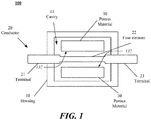
- FIG. 1 is a block diagram of a fuse 100 according to embodiments of the present disclosure.
- the fuse 100 includes a housing 10, a conductor 20 and porous material 30.
- the conductor 20 may be made from a variety of conductive materials (e.g ., copper, tin, silver, zinc, aluminum, alloys including such materials, or some combination of these).
- the conductor includes a terminal 21 and a terminal 23.
- the terminals 21, 23 are configured to electrically connect the fuse to a source of power (not shown) and a circuit component to be protected (not shown).
- the terminals 21, 23 are electrically connected by a fuse element 22.
- the terminals 21, 23 and the fuse element 22 may be made from the same material.
- the terminals 21, 23 and the fuse element 22 may be made from different materials. Furthermore, various techniques exist for forming the conductor 20 and/or the terminals 21, 23 and the fuse element 22 (e.g ., stamping, cutting, or the like). Furthermore, in the example where the terminals 21, 23 and the fuse element 22 are formed separately, the fuse element 22 and terminals 21, 23 can be joined using a variety of techniques (e.g ., soldering, welding, or the like).
- the porous material 30 is configured to "catch” or “retain” portions of the fuse element 22 when the fuse element 22 vaporizes due to an overcurrent and/or overvoltage condition.
- the porous material 30 is silicone foam.
- the porous material 30 comprises an open pore structure, meaning at least some pores of porous material 30 are disposed on an outer surface(s) of the porous material. In particular, at least some pores are disposed on the outer surface 132 of a piece of porous material 30 facing the fuse element 22. In this manner, the porous material 30 may present open pores directly facing the fuse element 22. As further detailed below, the porous material 30 may be disposed adjacent the fuse element 22, may be in contact with the fuse element 22, or may be spaced apart from the fuse element 22.
- pores of the porous material 30 facing the fuse element 22 or proximate the fuse element 22 may receive and retain vaporized or melted portions of the fuse element 22.
- the porous material 30 may be disposed as an insert or inlay within a housing of a fuse or may be molded within a housing of the fuse.
- the porous material 30 is configured to provide a large surface area to catch or retain the vaporized portions of the fuse element 22. Said differently, due to the pores (refer to FIG. 3 ) of the porous material 30, a large surface area relative to the inside surface of the housing 10 or the volume of the fuse element 22 is provided. In other words, the surface area of the porous material 30 may be larger than the surface area of the inside surface of the housing 10. As such, vaporized portions of the fuse element 22 may enter pores of the porous material 30 and may be distributed over the large surface area provided by the porous material 30 to increase the insulation resistance of the fuse 100 after melting of the fuse element 22. More specifically, the larger surface area of the porous material 30 provides a significantly larger area for vaporized portions of the fuse element 22 to be distributed and disposed. As such, the occurrence of carbon bridges may be reduced.
- the housing 10 includes a cavity 11 where the fuse element 22 and the porous material 30 are disposed.
- the terminals 21, 23 extend through the housing and are electrically connected to the fuse element 22.
- the housing 10 may be made from a variety of materials (e.g ., plastic, composite, epoxy, or the like).
- the housing 10 may be formed around the conductor 20 and the porous material 30.
- the housing 10 may be multi-part ( e.g ., refer to FIGS. 2 , 4 ) and the fuse 100 can be assembled by connecting the housing parts once the conductor 20 and the porous material 30 are placed in the cavity 11.
- the porous material 30 may be configured and/or selected to flex and or absorb some of the pressure created during the melting of the fuse element 22. More specifically, as the arc bums and vaporizes the fuse element 22, pressure within the housing 10 increases. Known fuses may be prone to rupture due to such pressure. In accordance with various embodiments of the disclosure, a flexible porous material may provide for the absorption of some of the pressure created when the arc bums to reduce and/or prevent rupture of the housing 10 due to the melting of the fuse element 22.
- silicone foam is used as the porous material 30.
- silicone foam provides for the porous material 30 not to degrade during the expected life span of the fuse 100.
- the porous material 30 may retain sufficient flexible properties and open pores to absorb and catch vaporized material from the fuse element 22 to prevent or reduce carbon bridges.
- An additional advantage of silicone foam is because the silicone foam may contain little or no carbon, wherein even in the event the silicone foam decomposes during a fuse event, carbon material is not formed from the foam.
- FIG. 2 illustrates an example of a top (or bottom) portion of the housing 10, referred to as housing 10a.
- the housing 10a includes a cavity 11, where porous material 30 may be disposed.
- the housing 10a includes recessed portions 12.
- the recessed portions 12 may be configured to allow the terminals 21, 23 to pass through the housing 10 when the housing 10 is assembled. More specifically, when the housing 10a is assembled with another housing 10a (refer to FIG. 4 ) the recessed portions 12 may allow the terminals 21, 23 to extend out of the housing 10 to facilitate electrical connection of the fuse 100 to a power source and circuit component.
- At least one housing 10a may include an alignment component configured to couple to another housing 10a.
- the housing 10a may also include alignment portions 13.
- the alignment portions 13 are configured to align with one another ( e.g. , when the housing 10a is assembled with another housing 10a).
- the alignment portions 13 may be configured to snap together, and or provide space for epoxy, or the like to be used to secure the housing 10 once assembled.
- the alignment portions 13 may be posts and holes ( e.g., as depicted in FIG. 2 ).
- the alignment portions may be rectangular or polygonal shaped protrusions with corresponding slots or receiving holes.
- FIG. 3 illustrates an example of porous material 30 according to an embodiment of the present disclosure.
- the porous material 30 includes pores 31.
- the pores 31 are configured to increase the surface area available to catch vaporized material of the fuse element 22.
- the pores 31 are configured to catch the vaporized material and prevent the material from passing through the porous material and from being disposed on inner surface (inside surface) of the fuse housing, i.e., the housing 10, where the vaporized material if disposed on the inside surface could lead to a carbon bridge being formed and reduced insulation resistance once the fuse element 22 has melted.
- the pores 31 are configured to trap and or retain the vaporized particles (e.g ., refer to FIG. 5b ) of the fuse element 22 in the event the fuse element 22 melts.
- FIG. 4 illustrates an exploded view of the fuse 100 according to embodiments of the present disclosure.
- the fuse 100 includes housing 10a, porous material 30, and conductor 20.
- the conductor 20 includes the terminals 21, 23 and the fuse element 22.
- the terminal 21 and terminal 23 may have a connection hole 25.
- the connection hole 25 may be configured to physically and electrically connect the fuse 100 to a source of power and circuit component.
- the holes 25 may be configured so the fuse 100 can be secured to a bolt or post.
- the conductor 20 may have alignment holes 24.
- the alignment holes 24 may be configured to align with the alignment portions 13 of the housings 10a as the fuse 100 is assembled. The alignment holes 24 and alignment portions 13 can then retain the housing 10 over the fuse element 22 once the fuse 100 is assembled.
- the alignment portions 13, when passed through the alignment holes 24 may form a structure retaining the porous material 30 centered over the fuse element 22. This may assist in ensuring substantially all or as much as desired of the vaporized material from the fuse element 22 is caught in the pores 31 (refer to FIG. 3 ) when the fuse element 22 melts.
- the porous material 30 may be disposed so the porous material is touching the fuse element 22. With other examples, the porous material 30 may be disposed so a space ( e.g., refer to FIGS. 1 and 7 ) exists between the terminals 21, 23 and the porous material 30. More specifically, a space exists between the terminals 21, 23 and the porous material 30 so a carbon bridge is unlikely to build up and provide a low resistance path between terminals 21, 23. With some examples, a space between terminals 21, 23 and the porous material 30 may exist, while the porous material 30 is close to or even touches the fuse element 22.
- a space e.g., refer to FIGS. 1 and 7
- the porous material 30 may be configured to cool the arc during melting of the fuse element, in addition to catching vaporized material. Accordingly, the fuse 100, in addition to providing higher insulation resistance, may provide quicker arc extinction than conventional fuses.
- FIGS. 5a-5b illustrate a cut-away view of an example fuse, fuse 100, before and after the fuse element melts.
- FIG. 5a illustrates the fuse 100 before the fuse element 22 has melted while
- FIG. 5b illustrates the fuse 100' once the fuse element 22 has melted.
- the porous material 30 is disposed in the cavity 11 of the housing 10 above and below the fuse element 22. Furthermore, the porous material 30 is centered about the fuse element 22. Terminals 21, 23 extend out from the housing 10 and provide a path for current to flow through the fuse element 22.
- the fuse element 22 melts and vaporizes as described above.
- the porous material 30 catches the vaporized material 40 of the fuse element 22.
- the vaporized material 40 is lodged in the pores 31 of the porous material 30 and is thereby substantially prevented from depositing on the inside surface of the housing 10. Accordingly, the path for current to flow between the terminals 21, 23 is interrupted and a high (e.g., > 1M ⁇ for a 70V fuse, or the like) insulation resistance is provided.
- the porous material 30 is provided with a pore structure capturing vaporized material 40 in a manner reducing the likelihood of formation of a continuous electrically conductive path between the terminal 21 and terminal 23 after a fusing event.
- the porous material 30 may have a pore size distribution adapted to contain solidified particles (referred to as the vaporized material 40) formed after solidification of melted or vaporized portions of the fuse element 22.
- the pore size of porous material 30 may range from several micrometers to several millimeters, such as between between five micrometers and five millimeters.
- the porous material 30 may have a surface area five times greater than the surface area of the inside of housing 10, or ten times greater, or one hundred times greater. For a given amount of vaporized material 40, this structure of porous material 30 provides a much larger surface area to condense upon without forming a continuous layer or bridge of conductive material, as compared to a fuse formed without the porous material 30.
- FIG. 6 is an image of an example fuse, fuse 100, according to embodiments of the present disclosure.
- terminals 21, 23 are connected to the fuse element 22 and extend out of the housing 10a.
- the alignment holes 24 are fit over the alignment portions 13 of the housing 10a and are configured to receive the alignment portions 13 (not shown) of another housing 10a (also not shown) to be assembled on the housing 10a.
- the porous material 30 is depicted disposed below the fuse element 22 and retained in position ( e.g ., substantially centered over the fuse element 22) by the alignment portions 13.
- another piece of porous material 30 may be disposed above the fuse element 22 and retained in position opposite the porous material 30 shown in FIG. 6 .
- FIG. 7 is an image of an example fuse, fuse 100, according to embodiments of the present disclosure.
- the terminals 21, 23 are connected to the fuse element 22 and extend out of the housing 10a.
- the porous material 30 is inserted into the cavity 11 of the housing 10a between ribs 15.
- the ribs 15 are positioned on either side of the porous material 30.
- the ribs 15 may have any of a variety of shapes (e.g ., ribs as shown, circular posts, or the like).
- the ribs 15 may be configured to support the porous material 30 during assembly ( e.g ., retain the material in the cavity 11) as well as support the porous material 30 after assembly and during use.
- the porous material 30 may be sized slightly larger than the distance between the ribs. As such, when the material is inserted between the ribs, the material may be biased to push against the ribs and thereby be retained in the cavity. With some example, the porous material 30 may be spaced away from the terminals 21, 23 to prevent a carbon bridge from forming on the surface of the porous material 30 itself and providing a low resistance path between the terminals 21, 23.
- the housing 10a may have ribs forming a rectangular box or bed.
- the rectangular bed may be sized slightly smaller than the porous material 30, such as when the porous material is in an uncompressed state before assembly in the fuse 100.
- the porous material 30 can be compressed and inserted into the rectangular bed. Due to the characteristic of the porous material 30, during assembly in the fuse 100, the porous material may be biased to expand against the rectangular bed and thereby be retained in the rectangular bed during assembly and use.
- FIG. 8A is a block diagram of another embodiment of fuse 100 shown in a side view as in Fig. 1 .
- FIG. 8B is a block diagram of fuse 100 of FIG. 8A in top plan view, with a top piece of porous material 30 removed for clarity.
- the fuse 100 may be similar to the embodiment of fuse 100 of FIG. 1 , with a difference being the porous material 30 includes a hole 45.
- the hole 45 may be disposed facing the fuse element 22 and in particular a middle region where melting and or vaporization may take place during a fusing event.
- providing a depression, cavity, or hole within a porous material may be useful to increase capture of vaporized or melted material.
- FIG. 8B is a block diagram of fuse 100 of FIG. 8A in top plan view, with a top piece of porous material 30 removed for clarity.
- the fuse 100 may be similar to the embodiment of fuse 100 of FIG. 1 , with a difference being the porous material 30 includes a hole 45.
- the hole 45 may
- the hole 45 may extend through the thickness of porous material 30.
- a depression may extend partially through the thickness of porous material 30.
- the embodiments are not limited in this context.
- the shape of the hole 45 may be circular, square, rectangular, or other convenient shape.
- the diameter or other lateral dimension of the hole 45 may be 2 mm to 10 mm.
- references to "an embodiment,” “an implementation,” “an example,” and/or equivalents is not intended to be interpreted as excluding the existence of additional embodiments also incorporating the recited features.
Landscapes
- Engineering & Computer Science (AREA)
- Manufacturing & Machinery (AREA)
- Chemical & Material Sciences (AREA)
- Composite Materials (AREA)
- Fuses (AREA)
Claims (14)
- Eine Sicherung (100), die Folgendes beinhaltet:ein Gehäuse (10) mit einem Hohlraum (11);ein Sicherungselement (22), das innerhalb des Hohlraums angeordnet ist;eine Vielzahl von Anschlüssen (21, 23), die sich aus dem Gehäuse erstrecken und elektrisch mit dem Sicherungselement verbunden sind; undporöses Material (30), das in dem Hohlraum angeordnet ist, wobei das poröse Material eine Vielzahl von Poren aufweist, wobei das poröse Material ferner eine offenporige Struktur beinhaltet, wobei mindestens einige der Poren auf einer dem Sicherungselement zugewandten äußeren Oberfläche des porösen Materials angeordnet sind, dadurch gekennzeichnet, dass es sich bei dem porösen Material um Silikonschaum handelt.
- Sicherung gemäß Anspruch 1, wobei das poröse Material konfiguriert ist, um verdampftes Material des Sicherungselements aufzufangen.
- Sicherung gemäß Anspruch 1, wobei das poröse Material über und unter dem Sicherungselement angeordnet ist oder wobei das poröse Material eine Porengröße von zwischen fünf Mikrometer und fünf Millimeter beinhaltet.
- Sicherung gemäß Anspruch 1, wobei das Gehäuse eine Vielzahl von Rippen beinhaltet, die konfiguriert sind, um in das poröse Material einzugreifen, wobei sich das poröse Material in einem komprimierten Zustand befindet, wenn die Sicherung zusammengebaut ist, und wobei optional die Vielzahl von Rippen ein Fach mit einer ersten Größe definiert, wobei das poröse Material in einem nicht komprimierten Zustand eine zweite Größe aufweist, die größer als die erste Größe ist.
- Sicherung gemäß Anspruch 1, wobei das Gehäuse konfiguriert ist, um das poröse Material um das Sicherungselement zu zentrieren.
- Sicherung gemäß Anspruch 1, wobei die Vielzahl von Anschlüssen einen ersten Anschluss und einen zweiten Anschluss umfasst und wobei das poröse Material von dem ersten Anschluss und dem zweiten Anschluss beabstandet ist.
- Sicherung gemäß Anspruch 1, wobei das Gehäuse einen ersten Abschnitt und einen zweiten Abschnitt beinhaltet, wobei mindestens einer von dem ersten Abschnitt und dem zweiten Abschnitt eine Ausrichtungskomponente umfasst, die konfiguriert ist, um den ersten Abschnitt und den zweiten Abschnitt aneinander zu koppeln.
- Sicherung gemäß Anspruch 1, wobei das poröse Material ein dem Sicherungselement zugewandtes Loch beinhaltet oder wobei das poröse Material von dem Sicherungselement beabstandet ist.
- Ein Verfahren zum Bilden einer Sicherung (100), das Folgendes beinhaltet:Bereitstellen einer Sicherungsstruktur, die ein Sicherungselement (22) und einen ersten Anschluss und einen zweiten Anschluss (21, 23), die mit dem Sicherungselement verbunden sind, beinhaltet;Bereitstellen eines ersten Gehäuseteils (10a) und eines zweiten Gehäuseteils (10a);Bereitstellen eines porösen Materials (30) zwischen dem Sicherungselement und mindestens einem von dem ersten Gehäuseteil und dem zweiten Gehäuseteil; undZusammenbauen des ersten Gehäuseteils mit dem zweiten Gehäuseteil, wobei der erste Gehäuseteil und der zweite Gehäuseteil einen Hohlraum (11) definieren, der das poröse Material hält,wobei das poröse Material eine Vielzahl von Poren aufweist, wobei das poröse Material ferner eine offenporige Struktur beinhaltet, wobei mindestens einige der Poren auf einer dem Sicherungselement zugewandten äußeren Oberfläche des porösen Materials angeordnet sind, dadurch gekennzeichnet, dass es sich bei dem porösen Material um Silikonschaum handelt.
- Verfahren gemäß Anspruch 9, wobei der erste Gehäuseteil einen ersten Hohlraumbereich definiert, der ein erstes Stück des porösen Materials hält, und wobei der zweite Gehäuseteil einen zweiten Hohlraumbereich definiert, der ein zweites Stück poröses Material hält.
- Verfahren gemäß Anspruch 9, wobei das Bereitstellen des porösen Materials das Anbringen des porösen Materials an einer inneren Oberfläche von mindestens einem von dem ersten Gehäuseteil und dem zweiten Gehäuseteil beinhaltet.
- Verfahren gemäß Anspruch 11, wobei das Anbringen das Kleben des Silikonschaums an die innere Oberfläche beinhaltet.
- Verfahren gemäß Anspruch 9, wobei mindestens einer von dem ersten Gehäuseteil und dem zweiten Gehäuseteil eine Vielzahl von Rippen beinhaltet, wobei das Zusammenbauen das Komprimieren des porösen Materials gegen die Vielzahl von Rippen beinhaltet.
- Verfahren gemäß Anspruch 9, wobei das poröse Material ein biegsames Material mit einer ersten Größe in einem nicht komprimierten Zustand beinhaltet und wobei das Zusammenbauen das Erzeugen einer zweiten Größe für den Hohlraum, die kleiner als die erste Größe ist, beinhaltet, wobei das poröse Material in einem komprimierten Zustand in dem Hohlraum gehalten wird.
Applications Claiming Priority (2)
| Application Number | Priority Date | Filing Date | Title |
|---|---|---|---|
| US201462001924P | 2014-05-22 | 2014-05-22 | |
| US14/716,268 US9607799B2 (en) | 2014-05-22 | 2015-05-19 | Porous inlay for fuse housing |
Publications (2)
| Publication Number | Publication Date |
|---|---|
| EP2947678A1 EP2947678A1 (de) | 2015-11-25 |
| EP2947678B1 true EP2947678B1 (de) | 2017-07-12 |
Family
ID=53199849
Family Applications (1)
| Application Number | Title | Priority Date | Filing Date |
|---|---|---|---|
| EP15169013.8A Active EP2947678B1 (de) | 2014-05-22 | 2015-05-22 | Poröse einlage für sicherungsgehäuse |
Country Status (2)
| Country | Link |
|---|---|
| US (1) | US9607799B2 (de) |
| EP (1) | EP2947678B1 (de) |
Families Citing this family (8)
| Publication number | Priority date | Publication date | Assignee | Title |
|---|---|---|---|---|
| US10074501B2 (en) | 2016-09-06 | 2018-09-11 | Littelfuse, Inc. | Non-arcing fuse |
| US10325746B2 (en) | 2016-11-15 | 2019-06-18 | Littelfuse, Inc. | Ventilated fuse housing |
| US11251009B1 (en) * | 2021-04-07 | 2022-02-15 | Littelfuse, Inc. | Fuse housing for safe outgassing |
| JP7713160B2 (ja) * | 2021-12-24 | 2025-07-25 | 株式会社オートネットワーク技術研究所 | ヒューズユニット |
| US11749483B1 (en) * | 2022-04-19 | 2023-09-05 | Littelfuse, Inc. | Fuse with compartmentalized body and parallel fuse elements |
| US11984286B2 (en) * | 2022-08-03 | 2024-05-14 | Littelfuse, Inc. | Inner chambers with blast attenuation geometry on fuses |
| CN115274376A (zh) * | 2022-08-12 | 2022-11-01 | 西安中熔电气股份有限公司 | 一种熔断器的熔体切断结构 |
| US11804351B1 (en) * | 2022-09-14 | 2023-10-31 | Littelfuse, Inc. | High breaking capacity fuse with fire-extinguishing pads |
Family Cites Families (27)
| Publication number | Priority date | Publication date | Assignee | Title |
|---|---|---|---|---|
| US550638A (en) | 1895-12-03 | Electrical protective | ||
| US1350055A (en) | 1918-11-15 | 1920-08-17 | Valley Electric Company | Cartridge-type fuse |
| US1474146A (en) * | 1919-08-23 | 1923-11-13 | Frederick A Feldkamp | Fuse cartridge |
| US1480225A (en) * | 1921-09-08 | 1924-01-08 | Western Electric Co | Electrical cut-out |
| US2077282A (en) * | 1931-03-10 | 1937-04-13 | Westinghouse Electric & Mfg Co | Electrical arc extinguishing and insulating material |
| GB443717A (en) | 1934-08-04 | 1936-03-04 | Charles Walter Cox | Improvements in or relating to electric fuses |
| US2143037A (en) * | 1937-05-25 | 1939-01-10 | Gen Electric | Fuse |
| US2483577A (en) | 1943-11-24 | 1949-10-04 | Westinghouse Electric Corp | Circuit interrupter |
| US3317690A (en) * | 1960-04-04 | 1967-05-02 | Driescher Spezialfab Fritz | Fuse cartridge |
| FR83398E (fr) * | 1963-04-05 | 1964-07-31 | Ferraz & Cie Lucien | Perfectionnements aux fusibles électriques |
| US3281557A (en) * | 1965-10-22 | 1966-10-25 | Mc Graw Edison Co | Indicator fuse for electric circuits |
| NL133832C (de) | 1966-03-04 | |||
| US3601737A (en) * | 1969-10-09 | 1971-08-24 | Gen Electrie Co | Fuse elements for dc interruption |
| US3818409A (en) * | 1972-05-17 | 1974-06-18 | J Pastors | Electric circuit breaking fuse |
| JPS5532380Y2 (de) * | 1975-11-26 | 1980-08-01 | ||
| US4109228A (en) * | 1977-04-18 | 1978-08-22 | Electric Power Research Institute, Inc. | Current limiting fuse with resinous arc-quenching filler |
| DE3118943A1 (de) * | 1981-05-13 | 1982-12-02 | Wickmann-Werke GmbH, 5810 Witten | Kleinstsicherung |
| US4506310A (en) * | 1984-03-19 | 1985-03-19 | At&T Bell Laboratories | Precision fusing arrangement |
| GB8519601D0 (en) * | 1985-08-05 | 1985-09-11 | Dubilier Plc | Time-lag fuses |
| EP0242149B1 (de) | 1986-04-16 | 1992-02-12 | Micropore International Limited | Verfahren zur Umhüllung eines Gegenstandes mit einem homogenen Block |
| DE9015208U1 (de) * | 1990-11-05 | 1991-01-17 | Wickmann-Werke GmbH, 5810 Witten | Elektrische Sicherung |
| US5095297A (en) * | 1991-05-14 | 1992-03-10 | Gould Inc. | Thin film fuse construction |
| US5420560A (en) * | 1991-07-29 | 1995-05-30 | Daito Communication Apparatus Co., Ltd. | Fuse |
| US9117615B2 (en) * | 2010-05-17 | 2015-08-25 | Littlefuse, Inc. | Double wound fusible element and associated fuse |
| CN102623273B (zh) | 2012-04-13 | 2015-02-18 | 苏州晶讯科技股份有限公司 | 小型熔断器 |
| US9911566B2 (en) * | 2013-10-18 | 2018-03-06 | Littelfuse, Inc. | Foam fuse filler and cartridge fuse |
| US20160064173A1 (en) * | 2014-08-26 | 2016-03-03 | Cooper Technologies Company | Fuse for high-voltage applications |
-
2015
- 2015-05-19 US US14/716,268 patent/US9607799B2/en active Active
- 2015-05-22 EP EP15169013.8A patent/EP2947678B1/de active Active
Also Published As
| Publication number | Publication date |
|---|---|
| EP2947678A1 (de) | 2015-11-25 |
| US20150340188A1 (en) | 2015-11-26 |
| US9607799B2 (en) | 2017-03-28 |
Similar Documents
| Publication | Publication Date | Title |
|---|---|---|
| EP2947678B1 (de) | Poröse einlage für sicherungsgehäuse | |
| US9892880B2 (en) | Insert for fuse housing | |
| JP6537619B2 (ja) | 内蔵式アーク・クエンチャーを備えたエア・スプリット・ヒューズにおけるワイヤ | |
| CN105518820B (zh) | 熔丝元件及熔丝单元 | |
| US10930463B2 (en) | Ventilated fuse housing | |
| US10490379B2 (en) | Surface mount fuse | |
| TWI610328B (zh) | 保險絲單元及保險絲元件 | |
| CN107615438B (zh) | 熔丝制造方法及熔丝 | |
| JP4175844B2 (ja) | ヒューズ | |
| US10283295B2 (en) | Protection device | |
| CN103733293B (zh) | 热过载保护装置 | |
| US20110181385A1 (en) | Thermal fuse | |
| US20150340181A1 (en) | Reflowable thermal fuse | |
| KR20160134492A (ko) | 일체형 복합 안전장치 | |
| US10177505B2 (en) | Protection element | |
| US10074501B2 (en) | Non-arcing fuse | |
| TW201805984A (zh) | 保護元件 | |
| TWI874551B (zh) | 限流保險絲及其製造方法 | |
| TW202333178A (zh) | 電熔斷器 | |
| KR101504132B1 (ko) | 복합보호소자 | |
| KR20240093117A (ko) | 퓨즈, 그를 포함하는 인쇄회로기판, 인쇄회로기판 제조방법 | |
| KR101742215B1 (ko) | 소형 퓨즈 제작 방법 | |
| KR101547427B1 (ko) | 복합보호소자 | |
| CN120126982A (zh) | 用于提高分断能力的具有铸造弧抑制材料的熔断器 |
Legal Events
| Date | Code | Title | Description |
|---|---|---|---|
| PUAI | Public reference made under article 153(3) epc to a published international application that has entered the european phase |
Free format text: ORIGINAL CODE: 0009012 |
|
| AK | Designated contracting states |
Kind code of ref document: A1 Designated state(s): AL AT BE BG CH CY CZ DE DK EE ES FI FR GB GR HR HU IE IS IT LI LT LU LV MC MK MT NL NO PL PT RO RS SE SI SK SM TR |
|
| AX | Request for extension of the european patent |
Extension state: BA ME |
|
| 17P | Request for examination filed |
Effective date: 20160511 |
|
| RBV | Designated contracting states (corrected) |
Designated state(s): AL AT BE BG CH CY CZ DE DK EE ES FI FR GB GR HR HU IE IS IT LI LT LU LV MC MK MT NL NO PL PT RO RS SE SI SK SM TR |
|
| GRAP | Despatch of communication of intention to grant a patent |
Free format text: ORIGINAL CODE: EPIDOSNIGR1 |
|
| STAA | Information on the status of an ep patent application or granted ep patent |
Free format text: STATUS: GRANT OF PATENT IS INTENDED |
|
| RIC1 | Information provided on ipc code assigned before grant |
Ipc: H01H 85/18 20060101ALI20161216BHEP Ipc: H01H 85/38 20060101AFI20161216BHEP Ipc: H01H 85/175 20060101ALI20161216BHEP Ipc: H01H 69/02 20060101ALI20161216BHEP |
|
| INTG | Intention to grant announced |
Effective date: 20170110 |
|
| GRAS | Grant fee paid |
Free format text: ORIGINAL CODE: EPIDOSNIGR3 |
|
| GRAA | (expected) grant |
Free format text: ORIGINAL CODE: 0009210 |
|
| STAA | Information on the status of an ep patent application or granted ep patent |
Free format text: STATUS: THE PATENT HAS BEEN GRANTED |
|
| AK | Designated contracting states |
Kind code of ref document: B1 Designated state(s): AL AT BE BG CH CY CZ DE DK EE ES FI FR GB GR HR HU IE IS IT LI LT LU LV MC MK MT NL NO PL PT RO RS SE SI SK SM TR |
|
| REG | Reference to a national code |
Ref country code: GB Ref legal event code: FG4D |
|
| REG | Reference to a national code |
Ref country code: CH Ref legal event code: EP |
|
| REG | Reference to a national code |
Ref country code: AT Ref legal event code: REF Ref document number: 909079 Country of ref document: AT Kind code of ref document: T Effective date: 20170715 |
|
| REG | Reference to a national code |
Ref country code: IE Ref legal event code: FG4D |
|
| REG | Reference to a national code |
Ref country code: DE Ref legal event code: R096 Ref document number: 602015003501 Country of ref document: DE |
|
| REG | Reference to a national code |
Ref country code: DE Ref legal event code: R082 Ref document number: 602015003501 Country of ref document: DE Representative=s name: MURGITROYD & COMPANY, DE |
|
| REG | Reference to a national code |
Ref country code: NL Ref legal event code: MP Effective date: 20170712 |
|
| REG | Reference to a national code |
Ref country code: LT Ref legal event code: MG4D |
|
| REG | Reference to a national code |
Ref country code: AT Ref legal event code: MK05 Ref document number: 909079 Country of ref document: AT Kind code of ref document: T Effective date: 20170712 |
|
| PG25 | Lapsed in a contracting state [announced via postgrant information from national office to epo] |
Ref country code: HR Free format text: LAPSE BECAUSE OF FAILURE TO SUBMIT A TRANSLATION OF THE DESCRIPTION OR TO PAY THE FEE WITHIN THE PRESCRIBED TIME-LIMIT Effective date: 20170712 Ref country code: FI Free format text: LAPSE BECAUSE OF FAILURE TO SUBMIT A TRANSLATION OF THE DESCRIPTION OR TO PAY THE FEE WITHIN THE PRESCRIBED TIME-LIMIT Effective date: 20170712 Ref country code: AT Free format text: LAPSE BECAUSE OF FAILURE TO SUBMIT A TRANSLATION OF THE DESCRIPTION OR TO PAY THE FEE WITHIN THE PRESCRIBED TIME-LIMIT Effective date: 20170712 Ref country code: NO Free format text: LAPSE BECAUSE OF FAILURE TO SUBMIT A TRANSLATION OF THE DESCRIPTION OR TO PAY THE FEE WITHIN THE PRESCRIBED TIME-LIMIT Effective date: 20171012 Ref country code: NL Free format text: LAPSE BECAUSE OF FAILURE TO SUBMIT A TRANSLATION OF THE DESCRIPTION OR TO PAY THE FEE WITHIN THE PRESCRIBED TIME-LIMIT Effective date: 20170712 Ref country code: SE Free format text: LAPSE BECAUSE OF FAILURE TO SUBMIT A TRANSLATION OF THE DESCRIPTION OR TO PAY THE FEE WITHIN THE PRESCRIBED TIME-LIMIT Effective date: 20170712 Ref country code: LT Free format text: LAPSE BECAUSE OF FAILURE TO SUBMIT A TRANSLATION OF THE DESCRIPTION OR TO PAY THE FEE WITHIN THE PRESCRIBED TIME-LIMIT Effective date: 20170712 |
|
| PG25 | Lapsed in a contracting state [announced via postgrant information from national office to epo] |
Ref country code: IS Free format text: LAPSE BECAUSE OF FAILURE TO SUBMIT A TRANSLATION OF THE DESCRIPTION OR TO PAY THE FEE WITHIN THE PRESCRIBED TIME-LIMIT Effective date: 20171112 Ref country code: GR Free format text: LAPSE BECAUSE OF FAILURE TO SUBMIT A TRANSLATION OF THE DESCRIPTION OR TO PAY THE FEE WITHIN THE PRESCRIBED TIME-LIMIT Effective date: 20171013 Ref country code: LV Free format text: LAPSE BECAUSE OF FAILURE TO SUBMIT A TRANSLATION OF THE DESCRIPTION OR TO PAY THE FEE WITHIN THE PRESCRIBED TIME-LIMIT Effective date: 20170712 Ref country code: PL Free format text: LAPSE BECAUSE OF FAILURE TO SUBMIT A TRANSLATION OF THE DESCRIPTION OR TO PAY THE FEE WITHIN THE PRESCRIBED TIME-LIMIT Effective date: 20170712 Ref country code: ES Free format text: LAPSE BECAUSE OF FAILURE TO SUBMIT A TRANSLATION OF THE DESCRIPTION OR TO PAY THE FEE WITHIN THE PRESCRIBED TIME-LIMIT Effective date: 20170712 Ref country code: RS Free format text: LAPSE BECAUSE OF FAILURE TO SUBMIT A TRANSLATION OF THE DESCRIPTION OR TO PAY THE FEE WITHIN THE PRESCRIBED TIME-LIMIT Effective date: 20170712 Ref country code: BG Free format text: LAPSE BECAUSE OF FAILURE TO SUBMIT A TRANSLATION OF THE DESCRIPTION OR TO PAY THE FEE WITHIN THE PRESCRIBED TIME-LIMIT Effective date: 20171012 |
|
| REG | Reference to a national code |
Ref country code: DE Ref legal event code: R097 Ref document number: 602015003501 Country of ref document: DE |
|
| PG25 | Lapsed in a contracting state [announced via postgrant information from national office to epo] |
Ref country code: RO Free format text: LAPSE BECAUSE OF FAILURE TO SUBMIT A TRANSLATION OF THE DESCRIPTION OR TO PAY THE FEE WITHIN THE PRESCRIBED TIME-LIMIT Effective date: 20170712 Ref country code: DK Free format text: LAPSE BECAUSE OF FAILURE TO SUBMIT A TRANSLATION OF THE DESCRIPTION OR TO PAY THE FEE WITHIN THE PRESCRIBED TIME-LIMIT Effective date: 20170712 Ref country code: CZ Free format text: LAPSE BECAUSE OF FAILURE TO SUBMIT A TRANSLATION OF THE DESCRIPTION OR TO PAY THE FEE WITHIN THE PRESCRIBED TIME-LIMIT Effective date: 20170712 |
|
| PLBE | No opposition filed within time limit |
Free format text: ORIGINAL CODE: 0009261 |
|
| STAA | Information on the status of an ep patent application or granted ep patent |
Free format text: STATUS: NO OPPOSITION FILED WITHIN TIME LIMIT |
|
| REG | Reference to a national code |
Ref country code: FR Ref legal event code: PLFP Year of fee payment: 4 |
|
| PG25 | Lapsed in a contracting state [announced via postgrant information from national office to epo] |
Ref country code: EE Free format text: LAPSE BECAUSE OF FAILURE TO SUBMIT A TRANSLATION OF THE DESCRIPTION OR TO PAY THE FEE WITHIN THE PRESCRIBED TIME-LIMIT Effective date: 20170712 Ref country code: SK Free format text: LAPSE BECAUSE OF FAILURE TO SUBMIT A TRANSLATION OF THE DESCRIPTION OR TO PAY THE FEE WITHIN THE PRESCRIBED TIME-LIMIT Effective date: 20170712 Ref country code: IT Free format text: LAPSE BECAUSE OF FAILURE TO SUBMIT A TRANSLATION OF THE DESCRIPTION OR TO PAY THE FEE WITHIN THE PRESCRIBED TIME-LIMIT Effective date: 20170712 Ref country code: SM Free format text: LAPSE BECAUSE OF FAILURE TO SUBMIT A TRANSLATION OF THE DESCRIPTION OR TO PAY THE FEE WITHIN THE PRESCRIBED TIME-LIMIT Effective date: 20170712 |
|
| 26N | No opposition filed |
Effective date: 20180413 |
|
| PG25 | Lapsed in a contracting state [announced via postgrant information from national office to epo] |
Ref country code: SI Free format text: LAPSE BECAUSE OF FAILURE TO SUBMIT A TRANSLATION OF THE DESCRIPTION OR TO PAY THE FEE WITHIN THE PRESCRIBED TIME-LIMIT Effective date: 20170712 |
|
| REG | Reference to a national code |
Ref country code: CH Ref legal event code: PL |
|
| REG | Reference to a national code |
Ref country code: BE Ref legal event code: MM Effective date: 20180531 |
|
| PG25 | Lapsed in a contracting state [announced via postgrant information from national office to epo] |
Ref country code: MC Free format text: LAPSE BECAUSE OF FAILURE TO SUBMIT A TRANSLATION OF THE DESCRIPTION OR TO PAY THE FEE WITHIN THE PRESCRIBED TIME-LIMIT Effective date: 20170712 |
|
| REG | Reference to a national code |
Ref country code: IE Ref legal event code: MM4A |
|
| PG25 | Lapsed in a contracting state [announced via postgrant information from national office to epo] |
Ref country code: LI Free format text: LAPSE BECAUSE OF NON-PAYMENT OF DUE FEES Effective date: 20180531 Ref country code: CH Free format text: LAPSE BECAUSE OF NON-PAYMENT OF DUE FEES Effective date: 20180531 |
|
| PG25 | Lapsed in a contracting state [announced via postgrant information from national office to epo] |
Ref country code: LU Free format text: LAPSE BECAUSE OF NON-PAYMENT OF DUE FEES Effective date: 20180522 |
|
| PG25 | Lapsed in a contracting state [announced via postgrant information from national office to epo] |
Ref country code: IE Free format text: LAPSE BECAUSE OF NON-PAYMENT OF DUE FEES Effective date: 20180522 |
|
| PG25 | Lapsed in a contracting state [announced via postgrant information from national office to epo] |
Ref country code: BE Free format text: LAPSE BECAUSE OF NON-PAYMENT OF DUE FEES Effective date: 20180531 |
|
| GBPC | Gb: european patent ceased through non-payment of renewal fee |
Effective date: 20190522 |
|
| PG25 | Lapsed in a contracting state [announced via postgrant information from national office to epo] |
Ref country code: MT Free format text: LAPSE BECAUSE OF NON-PAYMENT OF DUE FEES Effective date: 20180522 |
|
| PG25 | Lapsed in a contracting state [announced via postgrant information from national office to epo] |
Ref country code: TR Free format text: LAPSE BECAUSE OF FAILURE TO SUBMIT A TRANSLATION OF THE DESCRIPTION OR TO PAY THE FEE WITHIN THE PRESCRIBED TIME-LIMIT Effective date: 20170712 |
|
| PG25 | Lapsed in a contracting state [announced via postgrant information from national office to epo] |
Ref country code: GB Free format text: LAPSE BECAUSE OF NON-PAYMENT OF DUE FEES Effective date: 20190522 |
|
| PG25 | Lapsed in a contracting state [announced via postgrant information from national office to epo] |
Ref country code: PT Free format text: LAPSE BECAUSE OF FAILURE TO SUBMIT A TRANSLATION OF THE DESCRIPTION OR TO PAY THE FEE WITHIN THE PRESCRIBED TIME-LIMIT Effective date: 20170712 |
|
| PG25 | Lapsed in a contracting state [announced via postgrant information from national office to epo] |
Ref country code: CY Free format text: LAPSE BECAUSE OF FAILURE TO SUBMIT A TRANSLATION OF THE DESCRIPTION OR TO PAY THE FEE WITHIN THE PRESCRIBED TIME-LIMIT Effective date: 20170712 Ref country code: MK Free format text: LAPSE BECAUSE OF NON-PAYMENT OF DUE FEES Effective date: 20170712 Ref country code: HU Free format text: LAPSE BECAUSE OF FAILURE TO SUBMIT A TRANSLATION OF THE DESCRIPTION OR TO PAY THE FEE WITHIN THE PRESCRIBED TIME-LIMIT; INVALID AB INITIO Effective date: 20150522 |
|
| PG25 | Lapsed in a contracting state [announced via postgrant information from national office to epo] |
Ref country code: AL Free format text: LAPSE BECAUSE OF FAILURE TO SUBMIT A TRANSLATION OF THE DESCRIPTION OR TO PAY THE FEE WITHIN THE PRESCRIBED TIME-LIMIT Effective date: 20170712 |
|
| REG | Reference to a national code |
Ref country code: FR Ref legal event code: PLFP Year of fee payment: 9 |
|
| P01 | Opt-out of the competence of the unified patent court (upc) registered |
Effective date: 20230607 |
|
| PGFP | Annual fee paid to national office [announced via postgrant information from national office to epo] |
Ref country code: DE Payment date: 20250325 Year of fee payment: 11 |
|
| PGFP | Annual fee paid to national office [announced via postgrant information from national office to epo] |
Ref country code: FR Payment date: 20250401 Year of fee payment: 11 |