EP2947954B1 - Drahtloses kommunikationssystem, basisstation, kommunikationssteuerungsverfahren und nichtflüchtiges computerlesbares medium - Google Patents
Drahtloses kommunikationssystem, basisstation, kommunikationssteuerungsverfahren und nichtflüchtiges computerlesbares medium Download PDFInfo
- Publication number
- EP2947954B1 EP2947954B1 EP13871777.2A EP13871777A EP2947954B1 EP 2947954 B1 EP2947954 B1 EP 2947954B1 EP 13871777 A EP13871777 A EP 13871777A EP 2947954 B1 EP2947954 B1 EP 2947954B1
- Authority
- EP
- European Patent Office
- Prior art keywords
- base station
- bearer
- cell
- mobile station
- data
- Prior art date
- Legal status (The legal status is an assumption and is not a legal conclusion. Google has not performed a legal analysis and makes no representation as to the accuracy of the status listed.)
- Not-in-force
Links
Images








Classifications
-
- H—ELECTRICITY
- H04—ELECTRIC COMMUNICATION TECHNIQUE
- H04W—WIRELESS COMMUNICATION NETWORKS
- H04W76/00—Connection management
- H04W76/10—Connection setup
- H04W76/15—Setup of multiple wireless link connections
-
- H—ELECTRICITY
- H04—ELECTRIC COMMUNICATION TECHNIQUE
- H04W—WIRELESS COMMUNICATION NETWORKS
- H04W76/00—Connection management
- H04W76/10—Connection setup
- H04W76/12—Setup of transport tunnels
-
- H—ELECTRICITY
- H04—ELECTRIC COMMUNICATION TECHNIQUE
- H04W—WIRELESS COMMUNICATION NETWORKS
- H04W84/00—Network topologies
- H04W84/02—Hierarchically pre-organised networks, e.g. paging networks, cellular networks, WLAN [Wireless Local Area Network] or WLL [Wireless Local Loop]
- H04W84/04—Large scale networks; Deep hierarchical networks
- H04W84/042—Public Land Mobile systems, e.g. cellular systems
- H04W84/045—Public Land Mobile systems, e.g. cellular systems using private Base Stations, e.g. femto Base Stations, home Node B
Definitions
- the present invention relates to a radio communication system, and more particularly, to network architecture in a small cell enhancement scenario.
- LTE Long Term Evolution
- 3GPP 3rd Generation Partnership Project
- LPN low-power node
- a dual-connectivity scenario has been proposed regarding the small cell enhancement (see Non-Patent literature 2).
- a macro cell provides a control plane (e.g., Radio Resource Control (RRC) connection and Non-Access Stratum (NAS) message forwarding) for a mobile station (User Equipment (UE)) and a small cell provides a user plane for the UE.
- RRC Radio Resource Control
- NAS Non-Access Stratum
- This example of the dual connectivity may be referred to as a C/U-plane split.
- the dual-connectivity scenario for the Control plane (C-plane), the macro cell can keep a good connection with the UE by a wide coverage using a low frequency band and to support mobility of the UE.
- the user plane (U-plane) the small cell can provide a local high throughput for the UE by using a wide bandwidth in a high frequency band.
- a small cell does not require transmission of existing cell specific signals/channels (e.g., Primary Synchronization Signal (PSS), Secondary Synchronization Signal (SSS), Cell-specific Reference Signal (CRS), Master Information Block (MIB), and System Information Block (SIB)) is also assumed.
- PSS Primary Synchronization Signal
- SSS Secondary Synchronization Signal
- CRS Cell-specific Reference Signal
- MIB Master Information Block
- SIB System Information Block
- a new small cell may be referred to as a phantom cell.
- a base station (eNB) or an LPN that provides a small cell may be referred to as a Phantom eNodeB (PhNB).
- WO 2011/137784 A1 discloses a method for accessing a base station, the method including: according to an access request transmitted by the UE, a current macro base station establishes a control-plane-connection with the UE, and allocates a first Cell-Radio Network Temporary Identity (C-RNTI) to the UE; when a measurement report of micro base stations reported by the UE is received, a micro base station is selected, according to a preset strategy, for the UE, thus a data-plane-connection is established between the UE and the micro base station, and the context information of the UE is informed to the micro base station, wherein, the context information includes the first C-RNTI allocated to the UE.
- C-RNTI Cell-Radio Network Temporary Identity
- the dual-connectivity scenario in which the C-plane is provided for UEs in a cell controlled by the MeNB and the U-plane is provided for the UEs in a cell controlled by the LPN has been proposed.
- a cell that provides the C-Plane in the dual-connectivity scenario is referred to as a primary cell (PCell) and a cell that provides the U-Plane in the dual-connectivity scenario is referred to as a secondary cell (SCell).
- PCell primary cell
- SCell secondary cell
- a mobility management apparatus i.e., Mobility Management Entity (MME)
- MME Mobility Management Entity
- E-RAB Authentication Entity
- S5/S8 bearer a procedure for establishing the U-Plane bearer
- NAS message e.g., Attach Request or Service Request
- the MME need to set a data bearer that passes through an LPN (SCell), which is different from the MeNB (PCell), in response to the NAS message received through the MeNB (PCell).
- SCell LPN
- PCell MeNB
- PCell MeNB
- one object of the present invention is to provide a radio communication system, a base station, a mobile station, a communication control method, and a program that contribute to a simple establishment of a U-Plane bearer in the dual-connectivity scenario.
- a radio communication system includes: a first base station that operates a first cell; at least one second base station, each of which operates a second cell; a core network that includes a mobility management apparatus and a data transfer apparatus; and a mobile station.
- the mobile station has a capability to establish a data radio bearer in the second cell when the mobile station has established a signaling radio bearer in the first cell.
- the first base station is configured to receive, from the mobile station through the signaling radio bearer, a signal containing a NAS message that causes a setup of a data bearer in the data transfer apparatus.
- the first base station is further configured to send, when forwarding the NAS message to the mobility management apparatus, a control message that causes a suspension of the setup of the data bearer to the mobility management apparatus, and send, after sending the control message, a setup request for setting up the data bearer to the mobility management apparatus, wherein the first base station is further configured to receive measurement information regarding the at least one second base station from the mobile station, and select, from the at least one second base station, a selected base station to terminate the data bearer, and the setup request contains base station information indicating the selected base station that has been selected from the at least one second base station.
- a first base station includes: a radio communication unit that operates a first cell; and a controller.
- the controller is configured to receive, from a mobile station through a signaling radio bearer in the first cell, a signal containing a NAS message that causes a setup of a data bearer in a data transfer apparatus within a core network.
- the mobile station has a capability to establish a data radio bearer in a second cell of a second base station when the mobile station has established the signaling radio bearer in the first cell.
- the controller is further configured to send, when forwarding the NAS message to a mobility management apparatus within the core network, a control message that causes a suspension of the setup of the data bearer to the mobility management apparatus, and send, after sending the control message, a setup request for setting up the data bearer to the mobility management apparatus, wherein the controller is further configured to receive measurement information regarding at least one second base station from the mobile station, and select, from the at least one second base station, a selected base station to terminate the data bearer, and the setup request contains base station information indicating the selected base station that has been selected from the at least one second base station.
- a mobile station that is used in combination with the radio communication system according to the first aspect stated above, and includes a radio communication unit and a controller.
- the controller is configured to control the radio communication unit to receive configuration information regarding the data radio bearer from the first base station and receive or transmit user data through the second cell.
- a communication control method in a first base station that operates a first cell includes:
- a program includes instructions for causing a computer to perform the communication control method according to the above third aspect.
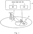
- Fig. 1 shows a configuration example of a radio communication system according to this embodiment.
- the radio communication system according to this embodiment includes a first base station 1, a second base station 2, a mobile station 4, and a core network 5.
- the base stations 1 and 2 operate a first cell 10 and a second cell 20, respectively.
- the core network 5 includes a mobility management apparatus 6 and a data transfer apparatus 7.
- the radio communication system according to this embodiment is an LTE system will be described as an example.
- the first base station 1 corresponds to an MeNB
- the second base station 2 corresponds to an LPN
- the mobile station 4 corresponds to a UE
- the core network 5 corresponds to an Evolved Packet Core (EPC)
- the mobility management apparatus 6 corresponds to a Mobility Management Entity (MME)
- the data transfer apparatus 7 corresponds to a Serving Gateway (S-GW).
- EPC Evolved Packet Core
- MME Mobility Management Entity
- S-GW Serving Gateway
- the radio communication system applies the dual connectivity to the cells 10 and 20. That is, the UE 4 supports the dual connectivity. In other words, the UE 4 has a capability to establish a data radio bearer (DRB) in the cell 20 when the UE 4 has established a signaling radio bearer (SRB) in the cell 10.
- the LPN 2 provides U-Plane services for the UE 4 in the cell 20. In other words, the LPN 2 establishes the DRB with the UE 4 in the cell 20 and transfers user data of the UE 4.
- the MeNB 1 provides C-plane services in the cell 10 for the UE 4, which establishes the DRB with the LPN 2.
- the MeNB 1 establishes the SRB with the UE 4 in the cell 10 and provides RRC signaling, for example, to establish and modify the DRB in the cell 20 of the LPN 2, and NAS message transfer between the EPC 5 and the UE 4.
- the MeNB 1 may transmit, on a downlink channel of the cell 10 (e.g., Physical Broadcast Channel (PBCH) or Physical Downlink Shared Channel (PDSCH)), master information (e.g., system bandwidth and the number of transmission antennas) and system information (e.g., parameters regarding the DRB in the cell 20) regarding the cell 20 of the LPN 2.
- PBCH Physical Broadcast Channel
- PDSCH Physical Downlink Shared Channel
- the MeNB 1 may not provide all the C-plane services regarding the UE 4.
- the LPN 2 may control a layer 1 (physical layer) and a layer 2 (Media Access Control (MAC) sublayer and Radio Link Control (RLC) sublayer) regarding the data radio bearer that is established for the LPN 2.
- the LPN 2 may receive layer 1/layer 2 control signals (e.g., Hybrid Automatic Repeat Request (H-ARQ) ACK, Channel Quality Indicator (CQI), Precoding Matrix Indicator (PMI), and Rank Indicator (RI)) using an uplink control channel (e.g., Physical Uplink Control Channel (PUCCH)) or an uplink data channel (e.g., Physical Uplink Shared Channel (PUSCH)).
- the LPN 2 may transmit downlink scheduling information, ACK/NACK for uplink transmission and the like to the UE 4 using a downlink control channel (e.g., Physical Downlink Control Channel (PDCCH)).
- a downlink control channel e.g
- the EPC 5 is a core network that is generally managed by an operator that provides mobile communication services.
- the EPC 5 has control plane (C-plane) functions including mobility management (e.g., location registration and location update) and bearer management (e.g., bearer establishment, bearer modification, and bearer release) of the UE 4, and user plane (U-plane) functions including transferring user data of the UE 4 between the MeNB 1 and an external network (not shown) and between the LPN 2 and the external network.
- the MME 6 contributes to the C-plane functions in the EPC.
- the S-GW 7 contributes to the U-plane functions in the EPC.
- the S-GW 7 is arranged at a boundary between the EPC 5 and a radio access network (RAN) including the MeNB 1 and the LPN 2.
- RAN radio access network
- Fig. 1 shows only one LPN 2 arranged in the cell 10 of the MeNB 1. However, a plurality of LPNs 2 and a plurality of second cells 20 may be arranged in the cell 10 of the MeNB 1.
- the MeNB 1 selects a selected LPN that establishes the U-Plane bearer for the UE 4 from at least one LPN 2.
- the MeNB 1 is configured to receive, from the UE 4 through the SRB in the cell 10, an RRC message (RRC signal) containing an initial NAS message that causes a setup of the U-Plane bearer (i.e., S1 bearer, E-RAB, or EPS bearer) in the S-GW 7.
- RRC signal an RRC message
- the NAS message that causes the setup of the U-Plane bearer is, for example, Attach Request, Service Request, or Tracking Area Update (TAU) Request.
- the MeNB 1 is configured to send, when forwarding the NAS message from the UE 4 that supports the dual connectivity to the MME 6, a control message that causes a suspension of the setup of the U-Plane bearer (i.e., an S1 bearer, an E-RAB, or an EPS bearer) to the MME 6.
- the control message that causes the suspension of the setup of the data bearer is hereinafter referred to as a "bearer setup suspension request".
- the bearer setup suspension request requests the MME 6 to suspend the establishment of the U-Plane bearer.
- the bearer setup suspension request may indicate that a LPN 2 that terminates the S1 bearer (hereinafter referred to as a selected LPN) has not yet been determined.
- the selected LPN is selected from at least one LPN 2 and terminates the S1 bearer for the UE 4.
- the MME 6 receives the bearer setup suspension request from the MeNB 1. Accordingly, the MME 6 can change the operation for setting up the U-Plane bearer according to whether the bearer setup suspension request has been received. In other words, the MME 6 can change the operation for setting up the U-Plane bearer according to whether the UE, which has originated the initial NAS message, supports the dual connectivity. That is, in some implementations, when the MME 6 has received the NAS message but has not received the bearer setup suspension request, the MME 6 initiates the setup of the U-Plane bearer that passes through the MeNB 1 in accordance with the normal bearer setup procedure in the LTE.
- the MME 6 when the MME 6 has received both of the NAS message and the bearer setup suspension request, the MME 6 performs a connection procedure for connecting the UE 4 to the core network 5 or a location update procedure regarding the UE 4 without performing the U-Plane bearer setup procedure.
- the MeNB 1 may send the bearer setup suspension request together with the NAS message that causes a setup of the U-Plane bearer.
- the MeNB 1 may include the bearer setup suspension request into an "S1-AP: INITIAL UE MESSAGE" that is used to forward the NAS message to the MME 6.
- the MeNB 1 may determine the selected LPN and send to the MME 6 a bearer setup request for setting up the U-Plane bearer.
- the bearer setup request may include LPN information indicating the selected LPN.
- the LPN information includes identification information that can specify the selected LPN (e.g., an address).
- the LPN information indicates, for example, a base station address of the selected LPN, a cell ID of the selected LPN, or a tunnel endpoint ID (TEID) of the selected LPN, or a combination thereof.
- the MME 6 receives the LPN information. Accordingly, the MME 6 can know an appropriate LPN 2 (i.e., the selected LPN) that should establish the S1 bearer and can set up the S1 bearer between the S-GW 7 and the appropriate selected LPN.
- Fig. 2 shows a first example of the bearer architecture related to the user data transfer in the cell 20.
- the radio bearer has already been described above. That is, the MeNB 1 establishes the SRB with the UE 4, and provides, in the cell 10, C-plane services including RRC signaling, for example, to establish and modify the DRB in the cell 20 and NAS message transfer between the EPC 5 and the UE 4. Meanwhile, the LPN 2 establishes the DRB with the UE 4 and transmits and receives the user data of the UE 4 on the cell 20.
- a signaling bearer with the EPC 5 (i.e., S1 signaling bearer using an S1-MME interface) is established between the MME 6 and the MeNB 1.
- the MeNB 1 establishes the S1 signaling bearer with the MME 6 and sends and receives S1 Application Protocol (S1-AP) messages to and from the MME 6.
- S1-AP S1 Application Protocol
- a data bearer with the EPC 5 (i.e., S1 bearer using an S1-U interface) is established between the S-GW 7 and the LPN 2.
- the LPN 2 establishes the S1 bearer with the S-GW 7 and sends and receives user data of the UE 4 to and from the S-GW 7.
- the MeNB 1 establishes a signaling bearer with the LPN 2.
- the signaling bearer between the MeNB 1 and the LPN 2 is established using, for example, an X2 interface.
- the X2 interface is an interface between eNBs.
- a case in which the LPN 2 is defined as a new node and a new interface different from the X2 interface is defined between the eNB and the LPN may be considered.
- the signaling bearer between the MeNB 1 and the LPN 2 may be established using this new interface.
- this new interface is provisionally referred to as an X3 interface.
- the MeNB 1 is configured to send, to the LPN 2 via an X2/X3 signaling bearer, the bearer context (hereinafter referred to as E-UTRAN Radio Access Bearer (E-RAB) configuration information) that is necessary to establish the S1 bearer with the S-GW 7 and the DRB with the UE 4 in the LPN 2.
- E-RAB is a radio access bearer including the DRB and the S1 bearer.
- the LPN 2 does not require the S1 signaling bearer with the MME 6 and can set up the DRB and the S1 bearer based on E-RAB configuration information supplied from the MeNB 1.
- a termination point of the S1 bearer (S1-U bearer) is different from a termination point of the S1 signaling bearer. That is, the LPN 2, not the MeNB 1, terminates the S1 bearer. That is, in the architecture shown in Fig. 2 , the C/U planes are separated not only with regard to the signaling in the RAN but also with regard to the interfaces between the EPC 5 and the RAN.
- the MeNB 1 is only required to perform signaling to establish the S1 bearer and the DRB necessary for the UE 4 to transmit and receive user data via the cell 20 and the LPN 2.
- the MeNB 1 needs not to terminate the S1 bearer (i.e., GPRS Tunneling Protocol (GTP) tunnel) for the communication of the UE 4 via the cell 20, and also needs not to perform forwarding of user data packets between the S1 bearer and the DRB.
- GTP GPRS Tunneling Protocol
- the S1 bearer is a GTP tunnel and the user data (data packet) is encapsulated in GTP tunnel packets to be transferred between the S-GW 7 and the LPN 2.
- the GTP tunnel packets that encapsulate downlink user data arrive at the LPN 2 by being subjected to routing and forwarding by routers arranged between the S-GW 7 and the LPN 2.
- the GTP tunnel packets are transferred without passing through the MeNB 1.
- the MeNB 1 need not carry out processing for terminating the S1 bearer and thus it is possible to reduce the processing load on the MeNB 1.
- the GTP tunnel packets do not flow through the X2/X3 interface between the MeNB 1 and the LPN 2, performance requirements on the capacity, the delay and the like of the X2/X3 interface are relaxed. It is possible, for example, to use a non-optical fiber line (e.g., wireless communication path) for the X2/X3 interface.
- a non-optical fiber line e.g., wireless communication path
- the GTP tunnel packets that encapsulate the user data may be transferred between the S-GW 7 and the LPN 2 via the MeNB 1.
- the MeNB 1 may function as a router (e.g., Internet Protocol (IP) router) and may perform routing and forwarding of the GTP tunnel packets.
- IP Internet Protocol
- the routing of the GTP tunnel packets that pass through the MeNB 1 can be achieved by setting up routing tables included in the S-GW 7, the LPN 2, and the MeNB 1.
- Fig. 3 shows a second example of the bearer architecture.
- the MeNB 1 performs routing and forwarding of the GTP tunnel packets.
- the MeNB 1 may have a proxy function to convert the IP addresses of the GTP tunnel packets.
- the MeNB 1 and the LPN 2 set up a tunnel 80 (e.g., GTP Tunnel) via the X2/X3 interface.
- the MeNB 1 further encapsulates the GTP tunnel packets, which encapsulate the user data on the S1 bearer between the S-GW 7 and the LPN 2, and forwards the encapsulated GTP tunnel packets using the tunnel 80.
- the tunnel 80 may be omitted. That is, the MeNB 1 may directly forward the GTP tunnel packets without performing further encapsulation of the GTP tunnel packets.
- the MeNB 1 need not terminate the S1 bearer.
- the MeNB 1 is only required to operate as a router that forwards the GTP tunnel packets and need not perform decapsulation processing to retrieve user packets. Accordingly, an increased processing load on the MeNB 1 which is due to the GTP tunnel termination does not occur.
- the MeNB 1 can monitor the GTP tunnel packets.
- the MeNB 1 can monitor, for example, the traffic amount of the GTP tunnel packets to be forwarded.
- the MeNB 1 can autonomously estimate the load on the cell 20 or the load on the LPN 2.
- the MeNB 1 according to this embodiment can determine deactivation of the cell 20 or the E-RAB that passes through the LPN 2, based on the traffic amount of the GTP tunnel packets monitored by the MeNB 1.
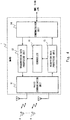
- Fig. 4 is a block diagram showing a configuration example of the MeNB 1.
- a radio communication unit 11 receives an uplink signal transmitted from the UE 4 via an antenna.
- a reception data processing unit 13 restores the received uplink signal.
- the resultant received data is forwarded to another network node (e.g., the MME 6 or the S-GW 7) via a communication unit 14.
- uplink user data received from the UE 4 in the cell 10 is forwarded to the S-GW 7.
- NAS data among control data received from the UE 4 is forwarded to the MME 6.
- the reception data processing unit 13 receives from a controller 15 the control data to be transmitted to the LPN 2 or the MME 6 and sends the control data to the LPN 2 or the MME 6 via the communication unit 14.
- a transmission data processing unit 12 obtains user data destined for the UE 4 from the communication unit 14, and generates a transport channel by performing error correction coding, rate matching, interleaving and the like on the user data.
- the transmission data processing unit 12 then generates a transmission symbol sequence by adding control information to the data sequence of the transport channel.
- the radio communication unit 11 generates a downlink signal by performing processing such as carrier wave modulation based on the transmission symbol sequence, frequency conversion, and signal amplification, and transmits the generated downlink signal to the UE 4.
- the transmission data processing unit 12 receives the control data to be transmitted to the UE 4 from the controller 15 and transmits the control data to the UE 4 via the radio communication unit 11.
- the controller 15 performs signaling with the MME 6, the LPN 2, and the UE 4 via the signaling bearers in order to enable the UE 4 to receive or transmit the user data through the cell 20 operated by the LPN 2. Specifically, the controller 15 sends, to the MME 6 via the S1 signaling bearer, the NAS message (e.g., Attach Request, Service Request, or TAU Request) that causes a setup of the U-Plane bearer. The controller 15 sends, to the LPN 2 via the X2/X3 signaling bearer, the E-RAB configuration information that is necessary to establish the S1 bearer and the DRB in the LPN 2.
- the NAS message e.g., Attach Request, Service Request, or TAU Request
- the controller 15 sends, to the UE 4 via the SRB in the cell 10, the DRB configuration information that is necessary to establish the DRB in the cell 20 in the UE 4. Further, as already described above, when forwarding to the MME 6 the NAS message from the UE 4 that supports the dual connectivity, the controller 15 sends the bearer setup suspension request to the MME 6.
- the controller 15 may be configured to receive measurement information regarding at least one LPN 2 (hereinafter referred to as LPN measurement information) from the UE 4 and select the selected LPN from at least one LPN 2.
- the LPN measurement information includes, for example, measurement results regarding the radio quality in the UE 4 (e.g., Reference Signal Received Power (RSRP) or Reference Signal Received Quality (RSRQ)).
- the LPN measurement information may further include a list of the LPNs 2 detected by the UE 4 (e.g., a list of base station IDs or a list of cell IDs).
- the controller 15 may select, as the selected LPN, a LPN 2 of which the radio quality measured by the UE 4 is the highest based on the LPN measurement information.
- the controller 15 may receive the LPN measurement information from the UE 4 and then determine the selected LPN. After that, the controller 15 may send to the MME 6 the bearer setup request containing the LPN information indicating the selected LPN.
- the initial NAS message e.g., Attach Request, Service Request, or TAU Request
- Fig. 5 is a block diagram showing a configuration example of the LPN 2.
- the functions and the operations of a radio communication unit 21, a transmission data processing unit 22, a reception data processing unit 23, and a communication unit 24 shown in Fig. 5 are similar to those of the corresponding elements of the base station 1 shown in Fig. 4 (i.e., the radio communication unit 11, the transmission data processing unit 12, the reception data processing unit 13, and the communication unit 14).
- a controller 25 of the LPN 2 receives the E-RAB configuration information from the MeNB 1 (controller 15) via the X2/X3 signaling bearer, and sets up the S1 bearer with the S-GW 7 and the SRB with the UE 4 in accordance with the E-RAB configuration information.
- Fig. 6 is a block diagram showing a configuration example of the UE 4.
- a radio communication unit 41 can communicate with both the cell 10 and the cell 20.
- the radio communication unit 41 may support carrier aggregation of a plurality of cells operated by different eNBs. In this case, the radio communication unit 41 can simultaneously use the plurality of cells 10 and 20 to transmit or receive user data.
- the radio communication unit 41 receives downlink signals from one or both of the eNB 1 and the LPN 2 via an antenna.
- a reception data processing unit 42 restores received data from the received downlink signal, and sends the received data to a data controller 43.
- the data controller 43 uses the received data according to the purpose thereof.
- a transmission data processing unit 44 and the radio communication unit 41 generate an uplink signal using transmission data supplied from the data controller 43, and transmit the uplink signal to one or both of the eNB 1 and the LPN 2.
- a controller 45 of the UE 4 controls the radio communication unit 41 to establish the SRB with the MeNB 1 on the cell 10.
- the controller 45 then receives from the MeNB 1 the DBB configuration information to establish the DRB with the LPN 2 and controls the radio communication unit 41 to transmit or receive the user data through the cell 20. Accordingly, the UE 4 can communicate with the LPN 2 via the DRB based on the signaling with the MeNB 1.
- controller 45 may measure downlink signals from at least one LPN 2 and transmit the LPN measurement information to the MeNB 1. As already stated above, the LPN measurement information is used by the MeNB 1 to determine the selected LPN.
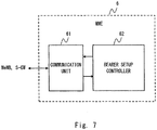
- Fig. 7 is a block diagram showing a configuration example of the MME 6.
- a communication unit 61 communicates with the MeNB 1 and the S-GW 7.
- a bearer setup controller 62 communicates with the MeNB 1 and the S-GW 7 via the communication unit 51, and controls the setup of the data bearer (E-RAB or S1 bearer) or the signaling bearer (S1 signaling bearer) in these apparatuses.
- E-RAB or S1 bearer the data bearer
- S1 signaling bearer S1 signaling bearer
- the bearer setup controller 62 requests the S-GW 7 to set up the S1 bearer and sends to the MeNB 1 the bearer configuration information regarding the E-RAB (i.e., E-RAB configuration information).
- the bearer setup controller 62 receives the bearer setup suspension request from the MeNB 1 when receiving the initial NAS message from the UE 4 that supports the dual connectivity. Accordingly, the bearer setup controller 62 can change the operation for setting up the U-Plane bearer according to whether the UE, which has originated the initial NAS message, supports the dual connectivity. That is, in some implementations, when the bearer setup controller 62 has received the NAS message but has not received the bearer setup suspension request, the bearer setup controller 62 initiates the setup of the U-Plane bearer that passes through the MeNB 1 in accordance with the normal bearer setup procedure in the LTE.
- the MME 6 when the MME 6 has received both of the NAS message and the bearer setup suspension request, the MME 6 performs a connection procedure for connecting the UE 4 to the core network 5 or a location update procedure regarding the UE 4 without executing the U-Plane bearer setup procedure.
- Fig. 8 is a block diagram showing a configuration example of the S-GW 7.
- a communication unit 71 establishes the S1 bearer with the LPN 2 and transmits or receives user data to or from the LPN 2 through the S1 bearer.
- the communication unit 71 may establish the S1 bearer with the MeNB 1 to enable the UE 4 to receive or transmit the user data through the cell.
- a communication unit 74 sets up the S5/S8 bearer with a Packet Data Network Gateway (P-GW) in the EPC 5 and transmits and receives the user data to and from another data transfer apparatus.
- P-GW Packet Data Network Gateway
- a transmission data processing unit 72 receives downlink user data destined for the UE 4 from the communication unit 74, and forwards the downlink user data to the S1 bearer based on mapping between the upstream side S5/S8 bearer and the downstream side S1 bearer.
- a reception data processing unit 73 receives uplink user data from the communication unit 71 and forwards the uplink user data to the S5/S8 bearer based on the mapping between the S5/S8 bearer and the S1 bearer.
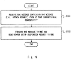
- Fig. 9 is a flowchart showing an operation example of the MeNB 1 regarding the establishment of the U-Plane bearer in the SCell.
- the MeNB 1 (controller 15) receives the RRC message containing the initial NAS message (e.g., Attach Request, Service Request, or TAU Request) from the UE 4, which supports the dual connectivity.
- the MeNB 1 forwards the NAS message received from the UE 4 to the MME 6 and sends the U-Plane bearer setup suspension request to the MME 6.
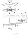
- Fig. 10 is a flowchart showing an operation example of the MME 6 regarding the establishment of the U-Plane bearer in the SCell.
- the MME 6 (bearer setup controller 62) determines whether a NAS message that causes a setup of the U-Plane bearer has been received from the MeNB 1.
- the MME 6 determines whether the bearer setup suspension request that accompanies the NAS message has been received.
- the MME 6 performs the connection process for connecting the UE 4 to the core network 5 or the location update process regarding the UE 4 without performing the bearer setup procedure (Step S203).
- Step S202 when the bearer setup suspension request has not been received (NO in Step S202), the MME 6 performs the normal bearer setup procedure in the LTE (Steps S204 and S205). In Step S206, the MME 6 sends a response message to the MeNB 1.
- Fig. 11 is a sequence diagram showing a first example of the procedure for establishing the U-Plane bearer in the SCell.
- the MeNB 1 determines the selected LPN in response to receiving the RRC message containing the NAS message from the UE 4 and sends the LPN information indicating the selected LPN to the MME 6 together with the bearer setup request.
- the MeNB 1 and the UE 4 establish an RRC connection.
- the UE 4 sends the NAS message (e.g., Attach Request, Service Request, or TAU Request) that requests for setting up the U-Plane bearer.
- the NAS message e.g., Attach Request, Service Request, or TAU Request
- the establishment of the RRC connection in the LTE includes establishment of the signaling radio bearer (i.e., SRB 1) and transfer of an initial uplink NAS message. That is, the NAS message transmitted in Step S302 is contained in an RRC Connection Setup Complete message transmitted to the MeNB 1 from the UE 4 at the last stage of the RRC connection establishment procedure (Step S301).
- SRB 1 signaling radio bearer
- Step S303 the MeNB 1 forwards the NAS message to the MME 6 and also sends the bearer setup suspension request to the MME 6.
- the MeNB 1 may include the bearer setup suspension request into the "S1-AP: INITIAL UE MESSAGE" that is used to forward the NAS message.
- Step S304 the MME 6 performs the connection process for connecting the UE 4 to the core network 5 or the location update process regarding the UE 4 without performing the bearer setup procedure.
- the MME 6 sends a response message (S1-AP message) containing the NAS message (e.g., Attach Accept) to the MeNB 1.
- Step S305 the MeNB 1 forwards the NAS message received from the MME 6 to the UE 4.
- the MeNB 1 may send the NAS message using an RRC Connection Reconfiguration message.
- the MeNB 1 determines the selected LPN from at least one LPN 2.
- the MeNB 1 may receive the LPN measurement information from the UE 4 and determine the LPN 2 of high reception quality at the UE 4 as the selected LPN.
- the MeNB 1 sends the bearer setup request in order to request the MME 6 to establish the U-Plane bearer for the UE 4.
- the MeNB 1 also sends the LPN information indicating the selected LPN to the MME 6 together with the bearer setup request.
- the MeNB 1 may include the LPN information into the S1-AP message that is used to forward the NAS message.
- Step S308 the MME 6 and the S-GW 7 perform the procedure for setting up the bearer for the UE 4. That is, the MME 6 sends a Create Session Request message to the S-GW 7.
- the S-GW 7 receives the Create Session Request message, generates a new entry in an EPS bearer context table, communicates with a P-GW (not shown) to configure a bearer context of the S5/S8 bearer, and configures the S-GW 7 side endpoint of the S1 bearer.
- the S-GW 7 sends a response (i.e., Create Session Response message) including an S1 bearer context to the MME 6.
- the S1 bearer context includes, for example, a tunnel endpoint identifier (TEID) and an address of the S-GW 7 in the U-plane.
- the TEID indicates the S-GW 7 side endpoint of the GTP tunnel as the S1 bearer.
- the MME 6 sends an INITIAL CONTEXT SETUP REQUEST message to the MeNB 1.
- the INITIAL CONTEXT SETUP REQUEST message includes an E-RAB bearer context (E-RAB configuration information).
- the MeNB 1 sends the E-RAB configuration information to the LPN 2 (in this example, selected LPN) via the X2/X3 signaling bearer.
- the E-RAB configuration information includes S1 bearer configuration information and DRB configuration information.
- the LPN 2 sets up the S1 bearer and the DRB in accordance with the E-RAB configuration information.
- the S1 bearer configuration information includes information that is necessary to establish the S1 bearer with the S-GW 7.
- the S1 bearer configuration information includes, for example, at least one of the E-RAB ID, a Quality Class Indicator (QCI), the IP address of the S-GW 7, the S-GW 7 side TEID of a GTP tunnel (S1 bearer), a security key, and a Temporary Mobile Subscriber Identity (TMSI) allocated to the UE 4.
- the DRB configuration information includes configuration information that is necessary to establish the DRB with the UE 4.
- the DRB configuration information includes, for example, the E-RAB ID, a Quality Class Indicator (QCI), and configuration information of the physical layer and the MAC sublayer.
- Step S311 the MeNB 1 transmits, to the UE 4 through the SRB in the cell 10, the DRB configuration information regarding the DRB in the cell 20.
- the DRB configuration information is transmitted using an RRC Connection Reconfiguration message.
- the UE 4 sets up the DRB in accordance with the DRB configuration information.
- Step S312 the MeNB 1 sends a message indicating E-RAB setup completion (i.e., INITIAL CONTEXT SETUP RESPONSE message) to the MME 6.
- This message includes LPN 2 side configuration information regarding the S1 bearer (e.g., the address and the TEID of the selected LPN).
- the MME 6 and the S-GW 7 modify the EPS bearer context based on the INITIAL CONTEXT SETUP RESPONSE message. That is, the MME 6 sends to the S-GW 7 a message (i.e., MODIFY BEARER REQUEST message) containing the TEID and the address of the selected LPN.
- the S-GW 7 updates the S1 bearer configuration with the TEID and the address of the LPN 2 received from the MME 6.
- Step S314 the UE 4 receives or transmits user data via the cell 20 and the LPN 2.
- Fig. 12 is a sequence diagram showing a second example of the procedure for establishing the U-Plane bearer in the SCell.
- the MeNB 1 receives, after sending the bearer setup request (Step S407) to the MME 6, the bearer context regarding the S1 bearer from the MME 6 (Step S409), sends the bearer context to the selected LPN (Step S410), and then sends the LPN information to the MME 6 after the S1 bearer has been configured in the selected LPN (Step S412).
- the MeNB 1 includes the LPN information into the S1-AP: INITIAL CONTEXT SETUP COMPLETE MESSAGE" that is used to notify the MME 6 of the completion of the bearer setup.
- Step S401 to S406 in Fig. 12 is similar to the processing in Steps S301 to S306 shown in Fig. 11 .
- Step S407 the MeNB 1 sends the bearer setup request to the MME 6 but does not send the LPN information.
- the processing in Steps S408 to S411 is similar to the processing in Steps S308 to S311 shown in Fig. 11 .
- Step S408 the MME 6 and the S-GW 7 perform the EPS bearer setup procedure.
- Step S409 the MME 6 sends the INITIAL CONTEXT SETUP REQUEST message to the MeNB 1.
- the INITIAL CONTEXT SETUP REQUEST message contains the E-RAB bearer context (E-RAB configuration information).
- the MeNB 1 sends the E-RAB configuration information to the selected LPN via the X2/X3 signaling bearer.
- the MeNB 1 transmits, to the UE 4 through the SRB in the cell 10, the DRB configuration information regarding the DRB in the cell 20.
- Step S412 the MeNB 1 sends a message indicating the E-RAB setup completion (i.e., INITIAL CONTEXT SETUP RESPONSE message) to the MME 6.
- This INITIAL CONTEXT SETUP RESPONSE message contains the LPN information indicating the selected LPN.
- the LPN information may be LPN 2 side configuration information regarding the S1 bearer (e.g., the address and the TEID of the selected LPN).
- the MME 6 and the S-GW 7 modify the EPS bearer context based on the INITIAL CONTEXT SETUP RESPONSE message.
- the MME 6 sends a message (i.e., MODIFY BEARER REQUEST message) containing the address and the TEID of the selected LPN to the S-GW 7.
- the S-GW 7 updates the S1 bearer configuration with the address and the TEID of the LPN 2 received from the MME 6.
- Step S414 the UE 4 receives or transmits user data via the cell 20 and the LPN 2.
- the MeNB 1 may select the MeNB 1 itself when there is no appropriate LPN 2.
- the MeNB 1 may configure the U-Plane bearer for the UE 4 in the cell 10 of the MeNB 1 when any LPN reception quality measured by the UE 4 is below a reference value.
- the MeNB 1 receives the LPN measurement information from the UE 4 and then determines the selected LPN based on the LPN measurement information.
- Fig. 13 is a sequence diagram showing a specific example of the U-Plane bearer establishment procedure according to this embodiment.
- the processing in Steps S501 to S505 is similar to the processing in Steps S301 to S305 shown in Fig. 11 (or Steps S401 to S405 shown in Fig. 12 ).
- the UE 4 transmits the LPN measurement information to the MeNB 1.
- the UE 4 may transmit the LPN measurement information using a Measurement Report message.
- the MeNB 1 determines the selected LPN based on the LPN measurement information.
- the processing in Steps S508 to S515 is similar to the processing in Steps S307 to S314 shown in Fig. 11 (or Steps S407 to S414 in Fig. 12 ).
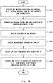
- Fig. 14 is a flowchart showing an operation example of the MeNB 1 according to this embodiment.
- the processing in Steps S601 and S602 is similar to the processing in Steps S101 and S102 shown in Fig. 9 .
- the MeNB 1 (controller 15) receives from the MME 6 a response to the NAS message.
- the MeNB 1 receives the LPN measurement information from the UE 4.
- the MeNB 1 determines the selected LPN that terminates the data bearer (S1 bearer) for the UE 4 based on the LPN measurement information.
- the MeNB 1 requests the MME 6 to set up a bearer regarding the selected LPN.
- the MeNB 1 sends to the MME 6 the LPN information, which indicates the selected LPN, and the bearer setup request.
- the MeNB 1 may send the LPN information to the MME 6 when sending to the MME 6 a bearer setup response (i.e., INITIAL CONTEXT SETUP RESPONSE message) after the setup of the U-Plane bearer (E-RAB) in the selected LPN has been completed.
- a bearer setup response i.e., INITIAL CONTEXT SETUP RESPONSE message
- Fig. 15 is a flowchart showing an operation example of the UE 4 according to this embodiment.
- the UE 4 (controller 45) sends the initial NAS message (e.g., Attach Request, Service Request, or TAU Request) that causes a setup of the U-Plane bearer.
- the UE 4 transmits the LPN measurement information to the MeNB 1 in response to receiving the LPN measurement request from the MeNB 1.
- the UE 4 may measure downlink signals from LPNs 2 in response to the instruction from the MeNB 1 (Step S702).
- the UE 4 may send to the MeNB 1, as the LPN measurement information, a measurement log that has been obtained in advance by the UE 4 during an idle mode.
- This embodiment shows first to third examples of the procedure for detecting the UE that supports the dual connectivity.
- the procedure for detecting the UE that supports the dual connectivity described in this embodiment can be combined with any of the first and second embodiments stated above.
- a configuration example of a radio communication system according to this embodiment is similar to that shown in Fig. 1 .
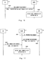
- Fig. 16 is a sequence diagram showing the first detection procedure.
- the UE 4 sends dual-connectivity support information to the MeNB 1 (Step S801).
- the UE 4 may notify the MeNB 1 that the UE 4 supports (or does not support) the dual connectivity.
- the MeNB 1 receives the dual-connectivity support information from the UE 4 and determines whether the UE 4 supports the dual connectivity (Step S802).
- the UE 4 may indicate the support of the dual connectivity using an RRC connection request message or RRC Connection Setup Complete message transmitted during the RRC connection establishment procedure.
- the UE 4 may indicate the support of the dual connectivity using an establishment cause contained in the RRC connection request message.
- the UE 4 may indicate the support of the dual connectivity using an attach type or request type contained in an Attach Request message as the initial NAS message.
- the MeNB 1 operates a special cell that can be accessed only by dual-connectivity-supporting UEs.
- the MeNB 1 determines that the UE 4 which has accessed this special cell as a dual-connectivity-supporting UE.
- the special cell which can be accessed only by dual-connectivity-supporting UEs, may be a cell which has an assignment of reference signals (RSs) different from that of a legacy cell that can be accessed by UEs (legacy UEs) that do not support the dual connectivity.
- RSs reference signals
- the special cell, which can be accessed only by dual-connectivity-supporting UEs may be a cell that uses a special frequency band that cannot be used by the legacy UEs.
- Fig. 17 is a sequence diagram showing the third detection procedure.
- the MeNB 1 obtains identification information (e.g., TMSI) of a dual-connectivity-supporting UE (Steps S901 and S902).
- the MeNB 1 receives the identification information of the UE 4 when the UE 4 connects to a network.
- the MeNB 1 receives an RRC Connection Request message containing the identification information of the UE 4 (e.g., TMSI) (Step S903).
- the MeNB 1 determines whether the UE 4 is a dual-connectivity-supporting UE or not, according to whether the identification information of the UE 4 coincides with the identification information of dual-connectivity-supporting UEs (Step S904).
- the MeNB 1 can determine whether the UE 4 supports the dual connectivity. Accordingly, the MeNB 1 can easily determine whether to set up the U-Plane bearer for the UE 4 to the MeNB 1 or to the LPN 2 according to whether the UE 4 supports the dual connectivity.
- All the communication control methods in the dual-connectivity scenario performed by the MeNB 1, the LPN 2, the UE 4, the MME 6, and the S-GW 7 described in the first to third embodiments may be implemented by using a semiconductor processing device including an Application Specific Integrated Circuit (ASIC).
- ASIC Application Specific Integrated Circuit
- these methods may be implemented by causing a computer system including at least one processor (e.g., microprocessor, Micro Processing Unit (MPU), Digital Signal Processor (DSP)) to execute a program.
- processor e.g., microprocessor, Micro Processing Unit (MPU), Digital Signal Processor (DSP)
- one or more programs including instructions to cause a computer system to perform the algorithms shown in the flowcharts and the sequence diagrams may be created and these programs may be supplied to a computer.
- Non-transitory computer readable media include any type of tangible storage media.
- Examples of non-transitory computer readable media include magnetic storage media (such as flexible disks, magnetic tapes, hard disk drives, etc.), optical magnetic storage media (e.g., magneto-optical disks), Compact Disc Read Only Memory (CD-ROM), CD-R, CD-R/W, and semiconductor memories (such as mask ROM, Programmable ROM (PROM), Erasable PROM (EPROM), flash ROM, Random Access Memory (RAM), etc.).
- These programs may be provided to a computer using any type of transitory computer readable media.
- Transitory computer readable media examples include electric signals, optical signals, and electromagnetic waves.
- Transitory computer readable media can provide a program to a computer via a wired communication line (e.g., electric wires, and optical fibers) or a wireless communication line.
- the LTE system has been mainly described.
- these embodiments may be applied to radio communication systems other than the LTE system, for example, a 3GPP Universal Mobile Telecommunications System (UMTS), a 3GPP2 CDMA2000 system (1xRTT, High Rate Packet Data (HRPD)), a Global System for Mobile Communications (GSM) system, or a WiMAX system.
- UMTS Universal Mobile Telecommunications System
- HRPD High Rate Packet Data
- GSM Global System for Mobile Communications
- WiMAX Worldwide Interoperability for Mobile Communications
Landscapes
- Engineering & Computer Science (AREA)
- Computer Networks & Wireless Communication (AREA)
- Signal Processing (AREA)
- Mobile Radio Communication Systems (AREA)
Claims (14)
- Funkkommunikationssystem, welches Folgendes aufweist:eine erste Basisstation (1), die dafür ausgelegt ist, eine erste Zelle (10) zu betreiben,wenigstens eine zweite Basisstation (2), die dafür ausgelegt ist, eine zweite Zelle (20) zu betreiben,ein Kernnetz (5), das eine Mobilitätsbehandlungsvorrichtung (6) und eine Datenübertragungsvorrichtung (7) aufweist, undeine Mobilstation (4) mit einer Fähigkeit zum Einrichten eines Datenfunkträgers in der zweiten Zelle (20), wenn die Mobilstation (4) einen signalisierenden Funkträger in der ersten Zelle (10) eingerichtet hat, wobeidie erste Basisstation (1) dafür ausgelegt ist, Folgendes auszuführen:Empfangen eines Signals, das eine NAS-Nachricht enthält, die eine Einrichtung eines Datenträgers in der Datenübertragungsvorrichtung (7) hervorruft, von der Mobilstation (4) durch den signalisierenden Funkträger,Senden einer Steuernachricht, die ein Aussetzen der Einrichtung des Datenträgers hervorruft, zur Mobilitätsbehandlungsvorrichtung (6), wenn die NAS-Nachricht zur Mobilitätsbehandlungsvorrichtung (6) weitergeleitet wird, undSenden einer Einrichtungsanforderung zum Einrichten des Datenträgers zur Mobilitätsbehandlungsvorrichtung (6) nach dem Senden der Steuernachricht, wobeidie erste Basisstation (1) ferner dafür ausgelegt ist, Messinformationen in Bezug auf die wenigstens eine zweite Basisstation (2) von der Mobilstation (4) zu empfangen und aus der wenigstens einen zweiten Basisstation (2) eine Basisstation zum Beenden des Datenträgers auszuwählen, unddie Einrichtungsanforderung Basisstationsinformationen enthält, welche die ausgewählte Basisstation angeben, die aus der wenigstens einen zweiten Basisstation (2) ausgewählt wurde.
- Funkkommunikationssystem nach Anspruch 1, wobei die Mobilitätsbehandlungsvorrichtung (6) dafür ausgelegt ist, die NAS-Nachricht zu empfangen, eine Verbindungsprozedur zur Verbindung der Mobilstation (4) mit dem Kernnetz (5) oder eine Ortsaktualisierungsprozedur in Bezug auf die Mobilstation (4) auszuführen, ohne eine Einrichtungsprozedur zum Einrichten des Datenträgers auszuführen, und zur ersten Basisstation (1) eine Antwort in Bezug auf die Verbindungsprozedur oder die Ortsaktualisierungsprozedur zu senden.
- Funkkommunikationssystem nach Anspruch 2, wobei die erste Basisstation (1) dafür ausgelegt ist, nach dem Empfang der Antwort die Mobilstation (4) anzuweisen, die erste Basisstation (1) über die Messinformationen in Bezug auf die wenigstens eine zweite Basisstation (2) zu informieren.
- Erste Basisstation (1), welche Folgendes aufweist:eine Funkkommunikationseinheit (11), welche dafür ausgelegt ist, eine erste Zelle (10) zu betreiben, undeine Steuereinrichtung (15), wobeidie Steuereinrichtung (15) dafür ausgelegt ist, Folgendes auszuführen:Empfangen eines Signals, das eine NAS-Nachricht enthält, die eine Einrichtung eines Datenträgers in einer Datenübertragungsvorrichtung (7) innerhalb eines Kernnetzes (5) veranlasst, von einer Mobilstation (4) durch einen signalisierenden Funkträger in der ersten Zelle (10), wobei die Mobilstation (4) die Fähigkeit hat, einen Datenfunkträger in einer zweiten Zelle (20) einer zweiten Basisstation (2) einzurichten, wenn die Mobilstation (4) den signalisierenden Funkträger in der ersten Zelle (10) eingerichtet hat,Senden einer Steuernachricht, die ein Aussetzen der Einrichtung des Datenträgers veranlasst, zu einer Mobilitätsbehandlungsvorrichtung (6), wenn die NAS-Nachricht zur Mobilitätsbehandlungsvorrichtung (6) innerhalb des Kernnetzes (5) weitergeleitet wird, undSenden einer Einrichtungsanforderung zum Einrichten des Datenträgers zur Mobilitätsbehandlungsvorrichtung (6) nach dem Senden der Steuernachricht, wobeidie Steuereinrichtung (15) ferner dafür ausgelegt ist, Messinformationen in Bezug auf die wenigstens eine zweite Basisstation (2) von der Mobilstation (4) zu empfangen und aus der wenigstens einen zweiten Basisstation (2) eine Basisstation zum Beenden des Datenträgers auszuwählen, unddie Einrichtungsanforderung Basisstationsinformationen enthält, welche die ausgewählte Basisstation angeben, die aus der wenigstens einen zweiten Basisstation (2) ausgewählt wurde.
- Erste Basisstation (1) nach Anspruch 4, wobei die Steuereinrichtung (15) dafür ausgelegt ist, Folgendes auszuführen:Empfangen eines Trägerkontexts in Bezug auf den Datenträger von der Mobilitätsbehandlungsvorrichtung (6) nach dem Senden der Einrichtungsanforderung zur Mobilitätsbehandlungsvorrichtung (6),Senden des Trägerkontexts zur ausgewählten Basisstation undSenden von Basisstationsinformationen, welche die ausgewählte Basisstation angeben, zur Mobilitätsbehandlungsvorrichtung (6), nachdem der Datenträger in der ausgewählten Basisstation konfiguriert wurde.
- Erste Basisstation (1) nach Anspruch 4 oder 5, wobei die Steuereinrichtung (15) dafür ausgelegt ist, festzustellen, ob die Mobilstation (4) die Fähigkeit aufweist.
- Erste Basisstation (1) nach Anspruch 6, wobei die Steuereinrichtung (15) dafür ausgelegt ist, von der Mobilstation (4) Attributinformationen zu empfangen, die das Vorhandensein oder Nichtvorhandensein der Fähigkeit angeben.
- Erste Basisstation (1) nach Anspruch 6, wobei
die erste Zelle (10) eine Zelle ist, zu der nur eine Mobilstation (4) gehören kann, welche die Fähigkeit aufweist, und
die Steuereinrichtung (15) dafür ausgelegt ist, auf der Grundlage eines Zugriffs der Mobilstation (4) auf die erste Zelle (10) festzustellen, dass die Mobilstation (4) die Fähigkeit aufweist. - Kommunikationssteuerverfahren in einer ersten Basisstation (1), die eine erste Zelle (10) betreibt, wobei das Kommunikationssteuerverfahren Folgendes aufweist:Empfangen eines Signals, das eine NAS-Nachricht enthält, die eine Einrichtung eines Datenträgers in einer Datenübertragungsvorrichtung (7) innerhalb eines Kernnetzes (5) veranlasst, von einer Mobilstation (4) durch einen signalisierenden Funkträger in der ersten Zelle (10), wobei die Mobilstation (4) die Fähigkeit hat, einen Datenfunkträger in einer zweiten Zelle (20) einer zweiten Basisstation (2) einzurichten, wenn die Mobilstation (4) den signalisierenden Funkträger in der ersten Zelle (10) eingerichtet hat,Senden einer Steuernachricht, die ein Aussetzen der Einrichtung des Datenträgers veranlasst, zu einer Mobilitätsbehandlungsvorrichtung (6), wenn die NAS-Nachricht zur Mobilitätsbehandlungsvorrichtung (6) innerhalb des Kernnetzes (5) weitergeleitet wird, undSenden einer Einrichtungsanforderung zum Einrichten des Datenträgers zur Mobilitätsbehandlungsvorrichtung (6) nach dem Senden der Steuernachricht, wobeibeim Verfahren ferner Messinformationen in Bezug auf wenigstens eine zweite Basisstation (2) von der Mobilstation (4) empfangen werden und aus der wenigstens einen zweiten Basisstation (2) eine Basisstation zum Beenden des Datenträgers ausgewählt wird, unddie Anforderung Basisstationsinformationen enthält, welche die aus der wenigstens einen zweiten Basisstation (2) ausgewählte Basisstation angeben.
- Verfahren nach Anspruch 9, welches ferner Folgendes aufweist:Empfangen eines Trägerkontexts in Bezug auf den Datenträger von der Mobilitätsbehandlungsvorrichtung (6) nach dem Senden der Einrichtungsanforderung zur Mobilitätsbehandlungsvorrichtung (6),Senden des Trägerkontexts zur ausgewählten Basisstation undSenden von Basisstationsinformationen, welche die ausgewählte Basisstation angeben, zur Mobilitätsbehandlungsvorrichtung (6), nachdem der Datenträger in der ausgewählten Basisstation konfiguriert wurde.
- Verfahren nach Anspruch 9 oder 10, wobei ferner festgestellt wird, ob die Mobilstation (4) die Fähigkeit aufweist.
- Verfahren nach Anspruch 11, wobei bei der Feststellung von der Mobilstation (4) Attributinformationen empfangen werden, die das Vorhandensein oder Nichtvorhandensein der Fähigkeit angeben.
- Verfahren nach Anspruch 11, wobei
die erste Zelle (10) eine Zelle ist, zu der nur eine Mobilstation (4) gehören kann, welche die Fähigkeit aufweist, und
bei der Feststellung auf der Grundlage eines Zugriffs auf die erste Zelle (10) durch die Mobilstation (4) festgestellt wird, ob die Mobilstation (4) die Fähigkeit aufweist. - Nichtflüchtiges computerlesbares Medium, das ein Programm speichert, um einen Computer zu veranlassen, ein Kommunikationssteuerverfahren in einer ersten Basisstation (1), welche eine erste Zelle (10) betreibt, auszuführen, wobei das Kommunikationssteuerverfahren Folgendes aufweist:Empfangen eines Signals, das eine NAS-Nachricht enthält, die eine Einrichtung eines Datenträgers in einer Datenübertragungsvorrichtung (7) innerhalb eines Kernnetzes (5) veranlasst, von einer Mobilstation (4) durch einen signalisierenden Funkträger in der ersten Zelle (10), wobei die Mobilstation (4) die Fähigkeit hat, einen Datenfunkträger in einer zweiten Zelle (20) einer zweiten Basisstation (2) einzurichten, wenn die Mobilstation (4) den signalisierenden Funkträger in der ersten Zelle (10) eingerichtet hat,Senden einer Steuernachricht, die ein Aussetzen der Einrichtung des Datenträgers veranlasst, zu einer Mobilitätsbehandlungsvorrichtung (6), wenn die NAS-Nachricht zur Mobilitätsbehandlungsvorrichtung (6) innerhalb des Kernnetzes (5) weitergeleitet wird, undSenden einer Einrichtungsanforderung zum Einrichten des Datenträgers zur Mobilitätsbehandlungsvorrichtung (6) nach dem Senden der Steuernachricht, wobeibeim Verfahren ferner Messinformationen in Bezug auf wenigstens eine zweite Basisstation (2) von der Mobilstation (4) empfangen werden und aus der wenigstens einen zweiten Basisstation (2) eine Basisstation zum Beenden des Datenträgers ausgewählt wird, unddie Anforderung Basisstationsinformationen enthält, welche die aus der wenigstens einen zweiten Basisstation (2) ausgewählte Basisstation angeben.
Applications Claiming Priority (2)
| Application Number | Priority Date | Filing Date | Title |
|---|---|---|---|
| JP2013004435 | 2013-01-15 | ||
| PCT/JP2013/007156 WO2014112000A1 (ja) | 2013-01-15 | 2013-12-05 | 無線通信システム、基地局、移動局、通信制御方法、及び非一時的なコンピュータ可読媒体 |
Publications (3)
| Publication Number | Publication Date |
|---|---|
| EP2947954A1 EP2947954A1 (de) | 2015-11-25 |
| EP2947954A4 EP2947954A4 (de) | 2016-08-10 |
| EP2947954B1 true EP2947954B1 (de) | 2018-06-13 |
Family
ID=51209129
Family Applications (1)
| Application Number | Title | Priority Date | Filing Date |
|---|---|---|---|
| EP13871777.2A Not-in-force EP2947954B1 (de) | 2013-01-15 | 2013-12-05 | Drahtloses kommunikationssystem, basisstation, kommunikationssteuerungsverfahren und nichtflüchtiges computerlesbares medium |
Country Status (5)
| Country | Link |
|---|---|
| US (1) | US9924556B2 (de) |
| EP (1) | EP2947954B1 (de) |
| JP (1) | JP6299605B2 (de) |
| SG (1) | SG11201505444VA (de) |
| WO (1) | WO2014112000A1 (de) |
Families Citing this family (15)
| Publication number | Priority date | Publication date | Assignee | Title |
|---|---|---|---|---|
| KR102287928B1 (ko) | 2013-09-27 | 2021-08-10 | 삼성전자 주식회사 | 이동 통신 시스템에서 복수의 캐리어를 이용하는 데이터 송수신 방법 및 장치 |
| WO2015136122A1 (en) * | 2014-03-14 | 2015-09-17 | Nec Europe Ltd. | Method, user equipment, master evolved node b and communication system for dual connectivity |
| ES2869306T3 (es) * | 2014-03-19 | 2021-10-25 | Alcatel Lucent | Conmutación del punto de terminación del plano de usuario de enlace ascendente de una puerta de enlace de servicio para un portador en operación de conectividad dual |
| CN105873133B (zh) * | 2015-01-23 | 2021-10-29 | 北京三星通信技术研究有限公司 | 双连接架构下支持业务本地分流的方法及设备 |
| US10805830B2 (en) | 2015-08-14 | 2020-10-13 | Telefonaktiebolaget Lm Ericsson (Publ) | Systems and methods for regulating user data traffic in a wireless network |
| EP4120600B1 (de) | 2016-02-18 | 2025-08-20 | Telefonaktiebolaget LM Ericsson (PUBL) | System, verfahren und vorrichtungen zur verwaltung der datenrate zur ebenenoptimierungssteuerung |
| DE112017000018T5 (de) * | 2016-04-06 | 2017-12-21 | Sony Corporation | Basisstation, virtuelle zelle, benutzergerät |
| WO2017175823A1 (ja) * | 2016-04-08 | 2017-10-12 | 株式会社Nttドコモ | 基地局及び送信制御方法 |
| CA3025677C (en) * | 2016-05-26 | 2022-05-17 | Nec Corporation | Communication system, control device, communication terminal, communication device, and communication method |
| US10306536B2 (en) | 2017-06-15 | 2019-05-28 | At&T Intellectual Property I, L.P. | Bearer split or fast switch capability indicator |
| CN111543117B (zh) * | 2017-11-14 | 2023-12-26 | 交互数字专利控股公司 | 在不活动状态中运行双连接 |
| US10652951B1 (en) * | 2018-02-22 | 2020-05-12 | Sprint Spectrum L.P. | Communicating with a wireless device via at least two access nodes |
| US11601841B2 (en) * | 2018-08-01 | 2023-03-07 | Nec Corporation | Radio station, radio communication method, non-transitory computer readable medium, and radio communication system |
| WO2020151957A1 (en) | 2019-01-21 | 2020-07-30 | Sony Corporation | Terminal device, infrastructure equipment and methods |
| CN112584550B (zh) * | 2019-09-27 | 2023-12-15 | 华为技术有限公司 | 一种双连接管理方法和通信装置 |
Family Cites Families (13)
| Publication number | Priority date | Publication date | Assignee | Title |
|---|---|---|---|---|
| CN101610504B (zh) * | 2008-06-18 | 2012-08-08 | 上海华为技术有限公司 | 接入、获取用户设备上下文及用户设备标识的方法和装置 |
| CN102469557B (zh) * | 2010-11-15 | 2014-08-13 | 华为技术有限公司 | 接入基站方法、基站和用户设备 |
| US8666415B2 (en) * | 2011-03-07 | 2014-03-04 | Htc Corporation | Method for canceling call initiation in radio access technology change |
| EP3249996A1 (de) * | 2011-04-01 | 2017-11-29 | InterDigital Patent Holdings, Inc. | Verfahren und vorrichtung zur steuerung der konnektivität zu einem netzwerk |
| KR102071695B1 (ko) * | 2011-07-12 | 2020-01-31 | 인터디지탈 패튼 홀딩스, 인크 | 다중 rat 액세스 모드 동작을 위한 방법 및 장치 |
| CN102883440B (zh) * | 2011-07-15 | 2015-11-25 | 华为技术有限公司 | 一种无线宽带通信方法,装置和系统 |
| EP2742767B1 (de) * | 2011-08-12 | 2018-04-04 | BlackBerry Limited | Abbruch einer verbindung in einem drahtlosen kommunikationssystem |
| EP2557889B1 (de) * | 2011-08-12 | 2019-07-17 | BlackBerry Limited | Vereinfachte ue- + enb-nachrichtenübermittlung |
| US9295095B2 (en) * | 2012-03-27 | 2016-03-22 | Blackberry Limited | UE preference indicator for suspension |
| US9247575B2 (en) * | 2012-03-27 | 2016-01-26 | Blackberry Limited | eNB storing RRC configuration information at another network component |
| JP5758351B2 (ja) * | 2012-06-22 | 2015-08-05 | 株式会社Nttドコモ | 無線通信システム |
| KR101708574B1 (ko) * | 2012-08-23 | 2017-02-20 | 인터디지탈 패튼 홀딩스, 인크 | 무선 시스템에서의 다중 스케줄러들을 이용한 동작 |
| US20160095029A1 (en) * | 2013-05-20 | 2016-03-31 | Nokia Technologies Oy | Method and apparatus for facilitating improved access for efficient cell change |
-
2013
- 2013-12-05 SG SG11201505444VA patent/SG11201505444VA/en unknown
- 2013-12-05 EP EP13871777.2A patent/EP2947954B1/de not_active Not-in-force
- 2013-12-05 JP JP2014557193A patent/JP6299605B2/ja not_active Expired - Fee Related
- 2013-12-05 WO PCT/JP2013/007156 patent/WO2014112000A1/ja not_active Ceased
- 2013-12-05 US US14/758,876 patent/US9924556B2/en active Active
Non-Patent Citations (1)
| Title |
|---|
| None * |
Also Published As
| Publication number | Publication date |
|---|---|
| EP2947954A1 (de) | 2015-11-25 |
| SG11201505444VA (en) | 2015-08-28 |
| US9924556B2 (en) | 2018-03-20 |
| JPWO2014112000A1 (ja) | 2017-01-19 |
| JP6299605B2 (ja) | 2018-03-28 |
| WO2014112000A1 (ja) | 2014-07-24 |
| EP2947954A4 (de) | 2016-08-10 |
| US20150365993A1 (en) | 2015-12-17 |
Similar Documents
| Publication | Publication Date | Title |
|---|---|---|
| US11589241B2 (en) | Radio communication system, base station, mobile station, communication control method, and computer readable medium | |
| US11356924B2 (en) | Radio communication system, base station, mobile station, communication control method, and computer readable medium | |
| US9924556B2 (en) | Radio communication system, base station, mobile station, communication control method, and non-transitory computer readable medium | |
| EP2947936B1 (de) | Drahtloses kommunikationssystem, basisstation, kommunikationssteuerungsverfahren und übergangsloses computerlesbares medium | |
| US10869350B2 (en) | Establishing simultaneous radio connection between a user equipment and two eNodeBs | |
| JP2023053398A (ja) | 無線アクセスネットワークノード及び無線端末並びにこれらの方法 | |
| EP2941048B1 (de) | Funkkommunikationssystem, basisstation, kommunikationssteuerungsverfahren und computerlesbares medium | |
| KR20170007469A (ko) | 데이터 통신에서의 경량 ota 시그널링 메카니즘을 위한 시스템, 장치, 및 방법 | |
| WO2013048096A1 (en) | Method and apparatus for selecting cell in wireless communication system | |
| HK1213720B (en) | Wireless communication system, base station and communication control method |
Legal Events
| Date | Code | Title | Description |
|---|---|---|---|
| PUAI | Public reference made under article 153(3) epc to a published international application that has entered the european phase |
Free format text: ORIGINAL CODE: 0009012 |
|
| 17P | Request for examination filed |
Effective date: 20150729 |
|
| AK | Designated contracting states |
Kind code of ref document: A1 Designated state(s): AL AT BE BG CH CY CZ DE DK EE ES FI FR GB GR HR HU IE IS IT LI LT LU LV MC MK MT NL NO PL PT RO RS SE SI SK SM TR |
|
| AX | Request for extension of the european patent |
Extension state: BA ME |
|
| DAX | Request for extension of the european patent (deleted) | ||
| A4 | Supplementary search report drawn up and despatched |
Effective date: 20160708 |
|
| RIC1 | Information provided on ipc code assigned before grant |
Ipc: H04W 76/02 20090101AFI20160704BHEP Ipc: H04W 16/32 20090101ALI20160704BHEP |
|
| 17Q | First examination report despatched |
Effective date: 20170816 |
|
| REG | Reference to a national code |
Ref country code: DE Ref legal event code: R079 Ref document number: 602013039052 Country of ref document: DE Free format text: PREVIOUS MAIN CLASS: H04W0076020000 Ipc: H04W0076100000 |
|
| RIC1 | Information provided on ipc code assigned before grant |
Ipc: H04W 76/02 00000000AFI20171201BHEP Ipc: H04W 84/04 20090101ALN20171201BHEP Ipc: H04W 16/32 20090101ALI20171201BHEP |
|
| GRAP | Despatch of communication of intention to grant a patent |
Free format text: ORIGINAL CODE: EPIDOSNIGR1 |
|
| INTG | Intention to grant announced |
Effective date: 20180117 |
|
| RIC1 | Information provided on ipc code assigned before grant |
Ipc: H04W 84/04 20090101ALN20180109BHEP Ipc: H04W 16/32 20090101ALI20180109BHEP Ipc: H04W 76/10 20180101AFI20180109BHEP |
|
| GRAS | Grant fee paid |
Free format text: ORIGINAL CODE: EPIDOSNIGR3 |
|
| GRAA | (expected) grant |
Free format text: ORIGINAL CODE: 0009210 |
|
| RIN1 | Information on inventor provided before grant (corrected) |
Inventor name: AMINAKA, HIROAKI Inventor name: FUTAKI, HISASHI |
|
| AK | Designated contracting states |
Kind code of ref document: B1 Designated state(s): AL AT BE BG CH CY CZ DE DK EE ES FI FR GB GR HR HU IE IS IT LI LT LU LV MC MK MT NL NO PL PT RO RS SE SI SK SM TR |
|
| REG | Reference to a national code |
Ref country code: GB Ref legal event code: FG4D |
|
| REG | Reference to a national code |
Ref country code: CH Ref legal event code: EP Ref country code: AT Ref legal event code: REF Ref document number: 1009856 Country of ref document: AT Kind code of ref document: T Effective date: 20180615 |
|
| REG | Reference to a national code |
Ref country code: IE Ref legal event code: FG4D |
|
| REG | Reference to a national code |
Ref country code: DE Ref legal event code: R096 Ref document number: 602013039052 Country of ref document: DE |
|
| REG | Reference to a national code |
Ref country code: NL Ref legal event code: MP Effective date: 20180613 |
|
| REG | Reference to a national code |
Ref country code: LT Ref legal event code: MG4D |
|
| PG25 | Lapsed in a contracting state [announced via postgrant information from national office to epo] |
Ref country code: ES Free format text: LAPSE BECAUSE OF FAILURE TO SUBMIT A TRANSLATION OF THE DESCRIPTION OR TO PAY THE FEE WITHIN THE PRESCRIBED TIME-LIMIT Effective date: 20180613 Ref country code: FI Free format text: LAPSE BECAUSE OF FAILURE TO SUBMIT A TRANSLATION OF THE DESCRIPTION OR TO PAY THE FEE WITHIN THE PRESCRIBED TIME-LIMIT Effective date: 20180613 Ref country code: SE Free format text: LAPSE BECAUSE OF FAILURE TO SUBMIT A TRANSLATION OF THE DESCRIPTION OR TO PAY THE FEE WITHIN THE PRESCRIBED TIME-LIMIT Effective date: 20180613 Ref country code: BG Free format text: LAPSE BECAUSE OF FAILURE TO SUBMIT A TRANSLATION OF THE DESCRIPTION OR TO PAY THE FEE WITHIN THE PRESCRIBED TIME-LIMIT Effective date: 20180913 Ref country code: NO Free format text: LAPSE BECAUSE OF FAILURE TO SUBMIT A TRANSLATION OF THE DESCRIPTION OR TO PAY THE FEE WITHIN THE PRESCRIBED TIME-LIMIT Effective date: 20180913 Ref country code: LT Free format text: LAPSE BECAUSE OF FAILURE TO SUBMIT A TRANSLATION OF THE DESCRIPTION OR TO PAY THE FEE WITHIN THE PRESCRIBED TIME-LIMIT Effective date: 20180613 Ref country code: CY Free format text: LAPSE BECAUSE OF FAILURE TO SUBMIT A TRANSLATION OF THE DESCRIPTION OR TO PAY THE FEE WITHIN THE PRESCRIBED TIME-LIMIT Effective date: 20180613 |
|
| PG25 | Lapsed in a contracting state [announced via postgrant information from national office to epo] |
Ref country code: GR Free format text: LAPSE BECAUSE OF FAILURE TO SUBMIT A TRANSLATION OF THE DESCRIPTION OR TO PAY THE FEE WITHIN THE PRESCRIBED TIME-LIMIT Effective date: 20180914 Ref country code: LV Free format text: LAPSE BECAUSE OF FAILURE TO SUBMIT A TRANSLATION OF THE DESCRIPTION OR TO PAY THE FEE WITHIN THE PRESCRIBED TIME-LIMIT Effective date: 20180613 Ref country code: HR Free format text: LAPSE BECAUSE OF FAILURE TO SUBMIT A TRANSLATION OF THE DESCRIPTION OR TO PAY THE FEE WITHIN THE PRESCRIBED TIME-LIMIT Effective date: 20180613 Ref country code: RS Free format text: LAPSE BECAUSE OF FAILURE TO SUBMIT A TRANSLATION OF THE DESCRIPTION OR TO PAY THE FEE WITHIN THE PRESCRIBED TIME-LIMIT Effective date: 20180613 |
|
| REG | Reference to a national code |
Ref country code: AT Ref legal event code: MK05 Ref document number: 1009856 Country of ref document: AT Kind code of ref document: T Effective date: 20180613 |
|
| PG25 | Lapsed in a contracting state [announced via postgrant information from national office to epo] |
Ref country code: NL Free format text: LAPSE BECAUSE OF FAILURE TO SUBMIT A TRANSLATION OF THE DESCRIPTION OR TO PAY THE FEE WITHIN THE PRESCRIBED TIME-LIMIT Effective date: 20180613 |
|
| PG25 | Lapsed in a contracting state [announced via postgrant information from national office to epo] |
Ref country code: CZ Free format text: LAPSE BECAUSE OF FAILURE TO SUBMIT A TRANSLATION OF THE DESCRIPTION OR TO PAY THE FEE WITHIN THE PRESCRIBED TIME-LIMIT Effective date: 20180613 Ref country code: RO Free format text: LAPSE BECAUSE OF FAILURE TO SUBMIT A TRANSLATION OF THE DESCRIPTION OR TO PAY THE FEE WITHIN THE PRESCRIBED TIME-LIMIT Effective date: 20180613 Ref country code: IS Free format text: LAPSE BECAUSE OF FAILURE TO SUBMIT A TRANSLATION OF THE DESCRIPTION OR TO PAY THE FEE WITHIN THE PRESCRIBED TIME-LIMIT Effective date: 20181013 Ref country code: AT Free format text: LAPSE BECAUSE OF FAILURE TO SUBMIT A TRANSLATION OF THE DESCRIPTION OR TO PAY THE FEE WITHIN THE PRESCRIBED TIME-LIMIT Effective date: 20180613 Ref country code: EE Free format text: LAPSE BECAUSE OF FAILURE TO SUBMIT A TRANSLATION OF THE DESCRIPTION OR TO PAY THE FEE WITHIN THE PRESCRIBED TIME-LIMIT Effective date: 20180613 Ref country code: PL Free format text: LAPSE BECAUSE OF FAILURE TO SUBMIT A TRANSLATION OF THE DESCRIPTION OR TO PAY THE FEE WITHIN THE PRESCRIBED TIME-LIMIT Effective date: 20180613 Ref country code: SK Free format text: LAPSE BECAUSE OF FAILURE TO SUBMIT A TRANSLATION OF THE DESCRIPTION OR TO PAY THE FEE WITHIN THE PRESCRIBED TIME-LIMIT Effective date: 20180613 |
|
| REG | Reference to a national code |
Ref country code: CH Ref legal event code: PK Free format text: BERICHTIGUNGEN |
|
| RIC2 | Information provided on ipc code assigned after grant |
Ipc: H04W 84/04 20090101ALN20180109BHEP Ipc: H04W 76/10 20180101AFI20180109BHEP Ipc: H04W 16/32 20090101ALI20180109BHEP |
|
| PG25 | Lapsed in a contracting state [announced via postgrant information from national office to epo] |
Ref country code: IT Free format text: LAPSE BECAUSE OF FAILURE TO SUBMIT A TRANSLATION OF THE DESCRIPTION OR TO PAY THE FEE WITHIN THE PRESCRIBED TIME-LIMIT Effective date: 20180613 Ref country code: SM Free format text: LAPSE BECAUSE OF FAILURE TO SUBMIT A TRANSLATION OF THE DESCRIPTION OR TO PAY THE FEE WITHIN THE PRESCRIBED TIME-LIMIT Effective date: 20180613 |
|
| REG | Reference to a national code |
Ref country code: DE Ref legal event code: R097 Ref document number: 602013039052 Country of ref document: DE |
|
| PLBE | No opposition filed within time limit |
Free format text: ORIGINAL CODE: 0009261 |
|
| STAA | Information on the status of an ep patent application or granted ep patent |
Free format text: STATUS: NO OPPOSITION FILED WITHIN TIME LIMIT |
|
| 26N | No opposition filed |
Effective date: 20190314 |
|
| PG25 | Lapsed in a contracting state [announced via postgrant information from national office to epo] |
Ref country code: DK Free format text: LAPSE BECAUSE OF FAILURE TO SUBMIT A TRANSLATION OF THE DESCRIPTION OR TO PAY THE FEE WITHIN THE PRESCRIBED TIME-LIMIT Effective date: 20180613 Ref country code: SI Free format text: LAPSE BECAUSE OF FAILURE TO SUBMIT A TRANSLATION OF THE DESCRIPTION OR TO PAY THE FEE WITHIN THE PRESCRIBED TIME-LIMIT Effective date: 20180613 |
|
| REG | Reference to a national code |
Ref country code: CH Ref legal event code: PL |
|
| PG25 | Lapsed in a contracting state [announced via postgrant information from national office to epo] |
Ref country code: MC Free format text: LAPSE BECAUSE OF FAILURE TO SUBMIT A TRANSLATION OF THE DESCRIPTION OR TO PAY THE FEE WITHIN THE PRESCRIBED TIME-LIMIT Effective date: 20180613 Ref country code: LU Free format text: LAPSE BECAUSE OF NON-PAYMENT OF DUE FEES Effective date: 20181205 |
|
| REG | Reference to a national code |
Ref country code: IE Ref legal event code: MM4A |
|
| REG | Reference to a national code |
Ref country code: BE Ref legal event code: MM Effective date: 20181231 |
|
| PG25 | Lapsed in a contracting state [announced via postgrant information from national office to epo] |
Ref country code: IE Free format text: LAPSE BECAUSE OF NON-PAYMENT OF DUE FEES Effective date: 20181205 |
|
| PG25 | Lapsed in a contracting state [announced via postgrant information from national office to epo] |
Ref country code: AL Free format text: LAPSE BECAUSE OF FAILURE TO SUBMIT A TRANSLATION OF THE DESCRIPTION OR TO PAY THE FEE WITHIN THE PRESCRIBED TIME-LIMIT Effective date: 20180613 Ref country code: BE Free format text: LAPSE BECAUSE OF NON-PAYMENT OF DUE FEES Effective date: 20181231 |
|
| PG25 | Lapsed in a contracting state [announced via postgrant information from national office to epo] |
Ref country code: LI Free format text: LAPSE BECAUSE OF NON-PAYMENT OF DUE FEES Effective date: 20181231 Ref country code: CH Free format text: LAPSE BECAUSE OF NON-PAYMENT OF DUE FEES Effective date: 20181231 |
|
| PG25 | Lapsed in a contracting state [announced via postgrant information from national office to epo] |
Ref country code: MT Free format text: LAPSE BECAUSE OF NON-PAYMENT OF DUE FEES Effective date: 20181205 |
|
| PG25 | Lapsed in a contracting state [announced via postgrant information from national office to epo] |
Ref country code: TR Free format text: LAPSE BECAUSE OF FAILURE TO SUBMIT A TRANSLATION OF THE DESCRIPTION OR TO PAY THE FEE WITHIN THE PRESCRIBED TIME-LIMIT Effective date: 20180613 |
|
| PG25 | Lapsed in a contracting state [announced via postgrant information from national office to epo] |
Ref country code: PT Free format text: LAPSE BECAUSE OF FAILURE TO SUBMIT A TRANSLATION OF THE DESCRIPTION OR TO PAY THE FEE WITHIN THE PRESCRIBED TIME-LIMIT Effective date: 20180613 |
|
| PG25 | Lapsed in a contracting state [announced via postgrant information from national office to epo] |
Ref country code: MK Free format text: LAPSE BECAUSE OF NON-PAYMENT OF DUE FEES Effective date: 20180613 Ref country code: HU Free format text: LAPSE BECAUSE OF FAILURE TO SUBMIT A TRANSLATION OF THE DESCRIPTION OR TO PAY THE FEE WITHIN THE PRESCRIBED TIME-LIMIT; INVALID AB INITIO Effective date: 20131205 |
|
| PGFP | Annual fee paid to national office [announced via postgrant information from national office to epo] |
Ref country code: GB Payment date: 20231220 Year of fee payment: 11 |
|
| PGFP | Annual fee paid to national office [announced via postgrant information from national office to epo] |
Ref country code: FR Payment date: 20231221 Year of fee payment: 11 Ref country code: DE Payment date: 20231214 Year of fee payment: 11 |
|
| REG | Reference to a national code |
Ref country code: DE Ref legal event code: R119 Ref document number: 602013039052 Country of ref document: DE |
|
| GBPC | Gb: european patent ceased through non-payment of renewal fee |
Effective date: 20241205 |
|
| PG25 | Lapsed in a contracting state [announced via postgrant information from national office to epo] |
Ref country code: DE Free format text: LAPSE BECAUSE OF NON-PAYMENT OF DUE FEES Effective date: 20250701 |
|
| PG25 | Lapsed in a contracting state [announced via postgrant information from national office to epo] |
Ref country code: GB Free format text: LAPSE BECAUSE OF NON-PAYMENT OF DUE FEES Effective date: 20241205 |
|
| PG25 | Lapsed in a contracting state [announced via postgrant information from national office to epo] |
Ref country code: FR Free format text: LAPSE BECAUSE OF NON-PAYMENT OF DUE FEES Effective date: 20241231 |