EP2948029B1 - Behälteranordnung - Google Patents
Behälteranordnung Download PDFInfo
- Publication number
- EP2948029B1 EP2948029B1 EP14705591.7A EP14705591A EP2948029B1 EP 2948029 B1 EP2948029 B1 EP 2948029B1 EP 14705591 A EP14705591 A EP 14705591A EP 2948029 B1 EP2948029 B1 EP 2948029B1
- Authority
- EP
- European Patent Office
- Prior art keywords
- tube
- container
- connector
- assembly
- closure
- Prior art date
- Legal status (The legal status is an assumption and is not a legal conclusion. Google has not performed a legal analysis and makes no representation as to the accuracy of the status listed.)
- Not-in-force
Links
- 239000012530 fluid Substances 0.000 claims description 15
- 238000005452 bending Methods 0.000 claims description 12
- 239000000853 adhesive Substances 0.000 claims description 5
- 230000001070 adhesive effect Effects 0.000 claims description 5
- 239000012790 adhesive layer Substances 0.000 claims description 5
- 235000013361 beverage Nutrition 0.000 claims description 5
- 230000000149 penetrating effect Effects 0.000 claims description 2
- 239000010902 straw Substances 0.000 description 29
- 230000035622 drinking Effects 0.000 description 10
- 238000003780 insertion Methods 0.000 description 7
- 230000037431 insertion Effects 0.000 description 7
- 239000000463 material Substances 0.000 description 7
- 238000004519 manufacturing process Methods 0.000 description 6
- 238000007789 sealing Methods 0.000 description 4
- 230000006378 damage Effects 0.000 description 3
- 239000007788 liquid Substances 0.000 description 3
- 230000035515 penetration Effects 0.000 description 3
- 239000011888 foil Substances 0.000 description 2
- 238000000034 method Methods 0.000 description 2
- 239000004698 Polyethylene Substances 0.000 description 1
- 238000004873 anchoring Methods 0.000 description 1
- 230000015572 biosynthetic process Effects 0.000 description 1
- 230000000694 effects Effects 0.000 description 1
- 230000009969 flowable effect Effects 0.000 description 1
- 235000015203 fruit juice Nutrition 0.000 description 1
- 238000010348 incorporation Methods 0.000 description 1
- 230000002427 irreversible effect Effects 0.000 description 1
- 239000010410 layer Substances 0.000 description 1
- 239000010813 municipal solid waste Substances 0.000 description 1
- 239000003921 oil Substances 0.000 description 1
- 239000005022 packaging material Substances 0.000 description 1
- -1 polyethylene Polymers 0.000 description 1
- 229920000573 polyethylene Polymers 0.000 description 1
- 239000000843 powder Substances 0.000 description 1
- 229920002379 silicone rubber Polymers 0.000 description 1
- 235000014214 soft drink Nutrition 0.000 description 1
- 239000007787 solid Substances 0.000 description 1
Images


Classifications
-
- A—HUMAN NECESSITIES
- A47—FURNITURE; DOMESTIC ARTICLES OR APPLIANCES; COFFEE MILLS; SPICE MILLS; SUCTION CLEANERS IN GENERAL
- A47G—HOUSEHOLD OR TABLE EQUIPMENT
- A47G21/00—Table-ware
- A47G21/18—Drinking straws or the like
-
- B—PERFORMING OPERATIONS; TRANSPORTING
- B65—CONVEYING; PACKING; STORING; HANDLING THIN OR FILAMENTARY MATERIAL
- B65D—CONTAINERS FOR STORAGE OR TRANSPORT OF ARTICLES OR MATERIALS, e.g. BAGS, BARRELS, BOTTLES, BOXES, CANS, CARTONS, CRATES, DRUMS, JARS, TANKS, HOPPERS, FORWARDING CONTAINERS; ACCESSORIES, CLOSURES, OR FITTINGS THEREFOR; PACKAGING ELEMENTS; PACKAGES
- B65D77/00—Packages formed by enclosing articles or materials in preformed containers, e.g. boxes, cartons, sacks or bags
- B65D77/22—Details
- B65D77/24—Inserts or accessories added or incorporated during filling of containers
- B65D77/28—Cards, coupons, or drinking straws
Definitions
- the present disclosure relates to packaging material and consumption utensils, in particular to (containers with) straws for drink containers.
- Straws and sealed drink containers are commonly known. Generally, both are provided together as an assembly, wherein the straw is formed to puncture (a predetermined portion of) the container for obtaining access to its contents for consumption. Similar arrangements may be provided for other flowable media such as oils, powders etc. The resultant opened assembly may however leak and/or lead to spilling of the contents, which are undesired.
- EP 1 362 800 discloses a straw adapted to be removably inserted into a press deformable container through a straw insert opening of the container, which is characterized by having a stopping part for stopping itself from being inserted through the straw insert opening, and an inlet hole at a position distant from the position of the stopping part by a distance substantially equal to the thickness of the container-forming material having the straw insert opening.
- the straw may comprise two tubes slidably fitted into each other so that the inlet hole can be opened and closed.
- WO 03/049583 also discloses a straw having an inner tube provided with a bellows within an outer tube, one end of the inner tube being terminated as a valve, whereby the suction force from the user provides a pressure difference across the bellows, causing the bellows to move the valve with sufficient force to open. When the suction force ceases, the valve closes, and it remains closed, even when the liquid in the drinking container is pressurized with pressure.
- US 2009/0065605 discloses an extensible straw for incorporation as an integral component of a disposable or collapsible beverage container, which has telescoping tubes extensible from the container, a screw cap and multiple seals preventing inadvertent leakage from the container whether the container is maintained upright or not.
- Such multi-part and telescoping straws consume much material, are prone to malfunctioning and leaking, and they are relatively complex and expensive to manufacture. Also, the movable tube may become detached from the rest of the assembly, undoing the desired benefits.
- a further known option is a cap over the free end (drinking end) of the straw, e.g. see Fig. 19 of US 2006/0196895 , US 2009/0065605 and JP 2000-095272 .
- Such cap is generally cumbersome to apply and it may fall off, inadvertently re-opening the straw so that it may leak.
- the assembly comprises a container for a fluid and the device.
- the container has a wall to be penetrated by the device.
- the device is for dispensing fluid to or from the container for a fluid having a wall to be penetrated by the device.
- the device comprises a tube with a first end, a second end and a lumen, a connector, and a closure, and the device is configured to penetrate the wall of the container to transfer the fluid to or from the container through the tube:
- the closure and the first end of the tube are configured to open and sealingly close the tube reversibly.
- the connector is configured to be inserted into and/or through the wall of the container forming a seal between the tube and the container and attaching the device substantially irreversibly to the container, with the device penetrating the wall and the first end of the tube extending out of the container.
- the tube facilitates accessing the contents of the container, e.g. for drinking a beverage contained in the container from the free first end of the tube.
- the second end of the tube may be sharpened, e.g. cut obliquely, to pierce the container wall.
- the closure prevents accidental leaking and/or spilling from the tube.
- the seal between the device and the container prevents leaking and/or spilling from an aperture in the wall through which the device extends.
- the substantially irreversible attachment of the device, in particular the connector thereof i.e. detachment being only possible by application of significant force and/or (at least partial) destruction of the device and/or the container, prevents accidental disconnection of the device and the container, which could result in leaks and spilling.
- the latter aspect is particularly relevant for use of the device as a drinking straw for young children, as it withstands their tendency to play and withdraw straws from drink containers and thus cause spills.
- the connector may engage and at least partly close against a relatively firm portion of the container wall when that has a weakened portion for facilitating penetration by the device. This reduces chances of leaking along the tube due to a damaged weakened wall portion.
- the connector may comprise a snapping arrangement for snap-fixing the device to, and in particular through, the container wall.
- Such snapping arrangement may comprise latches, barbs, flanges, etc., which may extend radially from the tube with respect to a direction of longitudinal extension of the tube.
- Such latches, barbs, flanges may, but need not necessarily, fully encircle the tube; one or two opposite radial barbs may suffice. This reduces material consumption and facilitates manufacture, transport and storage etc.
- the connector may comprise a screw thread for fixing the device to the container wall.
- the thread may have a varying thread pitch, a blind end and/or a gap towards the first end of the tube, such that the device may be screwed into and through the container wall, but cannot be screwed back out again.
- the connector may comprise an at least partially conical body, in particular flaring out towards the first end of the tube, allowing tightening the connection with increasing insertion depth of the device into the container.
- the conical body may be provided with the aforementioned screw thread.
- the connector may comprise a flange for abutting the container wall, to limit an insertion depth of the device into and/or through the container wall, and/or to provide the seal of the device to the container.
- the tube may be insertable into the connector and attachable thereto, to be fixed to each other or such that the tube is movable within the connector over a restricted distance in a longitudinal direction of extension of the tube. This facilitates manufacture, transport and/or assembly of the device. Fixation increases robustness and reliability. Freedom of motion may facilitate closing the first end of the tube.
- the closure comprises a plug that is insertable into the lumen of the tube to seal the tube and block fluid egress from it. This facilitates closing of the tube.
- a plug is generally easier to use for sealing an orifice such as the open end of a tube than a cap since a cap must fit around the tube whereas a plug may benefit from a rounded, tapered, conical and/or otherwise self-seeking shape.
- a cap tends to be larger, to require more material and to be more difficult to manufacture than a plug that may be a solid body and/or comprise one or more deformable flanges.
- a hollow tube tends to be more robust against outward forces than inward forces, whereas (relatively) significant forces against the tube wall may be required to provide a fluid-tight seal; a cap or a clamp having a such sealing inward force component is likely to deform and possibly buckle the tube which may result in losing the locking effect and leaking of the tube.
- a plug provides an outward force and assists maintaining shape of the tube.
- the closure and the connector are configured to open and sealingly close the connector reversibly with the closure. If the connector comprises no tube or if the first end of the tube is located within the connector and not extending out of it, the connector would provide an opening to the interior of the container and liquid may leak and/or be spilled from it. Such leaking and/or spilling from the connector may be prevented by closing the connector with the closure.
- the closure may be attached to a portion of the connector, which facilitates manufacture and use of the device and prevents loss of the closure, which may itself be only a small part.
- the closure may be substantially rigidly attached to a portion of the connector, which provides a well defined shape and therewith provides or at least conveys a notion of stability and robustness.
- At least two of the tube, the connector, and the closure may form an integral object, in particular being a unitary object.
- all three parts may form one integral, possibly unitary, object. This increases robustness and security of the device and it can facilitate manufacture of the integral portion.
- the connector and the closure form a unitary object, but separate from the tube, the separate objects may easily comprise different material properties, e.g. the tube being generally rigid and the closure and connector being generally elastic, so that they may close off and seal reliably against appropriate portions of the tube.
- the connector and closure may comprise or be of (silicone) rubber, whereas the tube comprises or is of polyethylene.
- the first end of the tube may have a predetermined bending portion, e.g. harmonica section, and the tube and the closure may be arranged so that the tube must be bent at the bending portion to be closed by the closure.
- a bent tube reduces size (e.g. height) of an assembly of a container and the device.
- a harmonica section facilitates bending without folding and prevents protruding sharp objects.
- At least part of the tube in particular the first end, has a longitudinal direction of extension out of and away from the connector portion in a first direction, and the closure extends in a direction for closing the tube that is substantially parallel to the direction of extension of the tube.
- the tube must make a U-turn to be closed, which can be readily done on purpose, but is hard to (un)do by accident, providing user friendliness and anti-leaking at the same time.
- a U-bent device also has a smaller volume.
- a device and a connector for a device disclosed herein comprising a lumen, with an inner size, for sealingly receiving at least part of a correspondingly sized, with respect to its outer size, tube and comprising a plug that is insertable into the lumen of the tube to seal the tube and block fluid egress from it.
- the plug protrudes from the connector.
- an aspect is an assembly comprising a container for a fluid and a device as provided herein, the container having a wall to be penetrated by the device, possibly in a predetermined perforation portion such as foil section in a drink carton.
- the assembly may comprise a sealed container comprising a fluid, in particular a beverage.
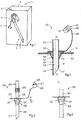
- Fig. 1 is a perspective view of an assembly 1 comprising a container 3 and a drinking straw device 5, in inoperable configuration, e.g. ready for sale.
- the device 5 has a tube 7, a connector 9 and a closure 11.
- the shown container 3 is in the form of a brick-shape carton, having liquid tight walls defining an interior volume containing a beverage (not indicated), here having film-coated cardboard walls.
- the container has a penetration portion 4 with an opening in the cardboard wall but being sealed by a film for penetration by the tube 7.
- Fig. 2 is a partial cross section view of an assembly 100 comprising a container 103 having a wall 113 coated with a film 114 on the interior side and a drinking straw device 105 attached by a connector 109 to the container 103 in operable configuration, i.e. the device 105 extends through the wall 113 of the container 103 with a first end 115 extending out of the container 103 and a second end 117 located within the container 103, so that fluid can be transferred to or from the interior volume V of the container 103 through a lumen 119 of the tube 105.
- the tube 107 is cylindrical with a longitudinal direction of extension A.
- the second end 117 of the tube 107 is sharply pointed, for punctuating the wall 113 of the container 103 and inserting the device 105 through it 103.
- the connector 109 comprises a plurality of barbs 121 extending from the tube 107 generally radially with respect to the direction of extension A and a flange 123.
- the free ends 125 of the barbs 121 and the flange 123 are separated by a distance comparable to the thickness of the container wall 113, wherein the barbs 121 have an outwardly curved surface towards the flange 123.
- the device may be inserted into and through the container wall 113 until the flange 123 abuts the outside of the wall 113, and the barbs 121 snap outwards behind the wall 113 so that the device is fixed, at least in the direction of extension A, to the container wall 113 and cannot be removed from it without force and/or damage.
- the device 105 may also be rotationally fixed, which further reduces chances of leaking between the container wall 113 and the connector 109.
- the closure 111 comprises a plug with flanges 127 encircling a main body 128 that is attached to the flange 123 by a connection in the form of a flexible beam 129, arranged so that the closure 111 can be inserted into the lumen 119 of the first end 115.
- the outer cross sectional shape of the closure 111 corresponds with the interior cross sectional shape of (the lumen 119 of) the tube 107 to provide a reliable seal (not shown).
- the flexible beam 129 may be provided with symbols, e.g. advertisement and/or brand indicia.
- Fig. 3 is a side view of a straw device 205 generally comparable to the embodiments of Figs. 1-2 .
- the connector 209 comprises a generally round conical main body 231 with increasing diameter from the second end 217 towards the first end 215 of the tube 107 terminating on a flange 223 and outwardly provided with a screw thread 221 for attachment to the wall of a container (not shown).
- the screw thread 221 has an upper end 225 at a distance d from the flange 223, which may be comparable to the thickness of the container wall through which the device is to extend.
- the upper end 225 of the screw thread 221 is extends at a smaller angle to the flange 223 than the remainder of the screw thread 223 so that the connector may be screwed into and through the container wall, but once the upper end 225 has passed the container wall it does not extend towards the interior surface of the container wall at a noticeable angle, so that the upper end 225 does not engage readily engage the container wall and the connector cannot readily be screwed back out of the wall again.
- the conical body 231 ensures an increasing deformation pressure against the container wall, so that a tight seal is provided between the connector and the container wall, preventing leakage there.
- plural coaxial screw threads with more or less than 360 degrees turn may be provided, e.g. down to a general bayonet-like connection.
- This embodiment 205 comprises a closure 211 in the form of a cap with a skirt wall 233 to be put over the first end 215 of the tube 207 for sealing that.
- the cap comprises an internal plug body 228 for insertion into the lumen of the tube 207 for easy closing and counteracting radially inwards forces by the cap onto the tube walls.
- the skirt wall 233 of the cap covers, in closed configuration, the very end of the tube 207, protecting it, e.g. to increase hygiene in the case of use as a drinking straw.
- the first end 215 of the tube comprises a flexible section 235, here formed as a bellows, for easily bending the tube 207 without kinking or folding it. This increases user friendliness of the tube 207 and facilitates (arranging the tube 207 and cap 211 for) closing the tube 207 with the closure 211.
- Fig. 4 is a side view of a detail of another embodiment 305 of a tube device, comprising a connector 309 with a main body 331 with varying diameter, here comprising a plurality of separate generally radially extending flanges 321 facilitating attachment of the device 205 into and through the container wall by simple straight insertion.
- Figs. 5A and 5B are perspective (partial) views of a further embodiment of a device 405.
- the connector 409 comprises barbs 421.
- the barbs 421 extend somewhat tangential to the axis A of the tube 407, as shown in cross section view in Fig. 5C (see indications "VC" in Fig. 5B ). This facilitates both straight insertion and insertion with a screwing motion through the container wall, the latter being found to be a natural movement for insertion, but not a straightforward motion for detachment, in particular not for children.
- the connector 409 has a flange 423 which is relatively elongated in one lateral direction with respect to the tube axis A, and relatively narrow in a perpendicular direction, reducing bulk and material consumption of the device 405.
- an upwardly tapering closure plug 428 is fixed, extending generally parallel to the tube axis A adjacent the plug 428 towards the first end 415 of the tube 407.
- the tubes first end 415 is provided with a bending portion 435, here a harmonica section, for bending the tube 407.
- the bending portion 435 is made so long and resilient that (the aperture of) the first end 415 can be arranged over the plug 428 as shown in Fig. 5B and is urged towards a sealed position.
- the tube 407 and the connector 409 may be movable in a direction along A for small distance, e.g. about the height of the connector.
- Fig 6 shows, similar to Fig. 2 , an embodiment of a device 500, wherein a connector 509 on a tube 505 is provided with a flange 523 (like the device of Fig. 2 ), to engage the wall 513 of a container 503.
- the flange 523 is adhered to the wall 503.
- an amount of adhesive 537 is provided around the tube 507.
- Suitable adhesion techniques are providing the container 503 and/or the bottom side of the flange 523 with an adhesive layer, possibly protected with a peel-off layer.
- a two-component adhesive with a first component on the container 503 and a second component on (the connector 509 of) the device 505 forming an adhesive layer on contacting together are also conceivable and may provide a securer seal than an adhesive layer on a single side.
- Fig. 7 shows an embodiment, generally similar to that of Figs. 2 and 3 , of a connector 609 and a plug closure 611 with plug body 628 attached together as a unitary device by a connection in the form of a flexible beam 629, arranged so that the closure 611 can be inserted into a lumen 637 of the connector 609.
- Fig. 8 is a top view of the embodiment of Fig. 7 with the flexible beam 629 unbent.
- the outer cross sectional shape of the closure 611 corresponds with the interior cross sectional shape of (the lumen 637 of) the connector 609 to provide a reliable seal (not shown), further, the outer cross sectional shape of the closure 611 corresponds with the interior cross sectional shape of (the lumen of) a tube (not shown) to be inserted through the connector 609 to complete a device 605.
- the closure 611 may close either aperture (connector and/or tube) and therewith close the container. This may be facilitated by providing at least part of (the lumen 637 of) the connector 609 and/or the plug closure 611 tapered and/or deformable, e.g. being elastically deformable and/or having flanges, like the closure 111 of Fig. 2 , providing a particularly reliable seal (not shown).
- a pull tab 639 facilitates removing the plug 611 when inserted in an aperture and opening the connector or tube, respectively.
- the disclosure is not restricted to the above described embodiments which can be varied in a number of ways within the scope of the claims.
- the tube wall may be provided with local outward and/or inward diameter variations, similar to formation of a harmonica portion for a bending portion.
- a flange may be larger, smaller, or absent altogether. It is noted that sealing foils in common containers tends to be flexible up to a degree that a seal may be readily provided against a generally straight and constant-diameter tube. Opposite oriented barbs and/or flanges (cf. Fig. 4 but without a varying-diameter core) may serve to fix the tube (at least in longitudinal direction of extension) to the container wall, a seal being provided by the container wall material.
- the device may comprise more than one bending portion.
- a connector portion e.g. a flange, may be provided with an adhesive to attach and seal the device to the container, e.g. an adhesive with a tear-off tab. Preferably the tab remains attached to the device so that loose trash is prevented.
- the container may be shaped as a cup with a lid or a pouch, e.g. containing a soft drink or a fruit juice.
Landscapes
- Engineering & Computer Science (AREA)
- Mechanical Engineering (AREA)
- Closures For Containers (AREA)
Claims (11)
- Anordnung (1), die einen Behälter (3) für ein Fluid und eine Vorrichtung (5) aufweist, wobei der Behälter eine durch die Vorrichtung zu penetrierende Wand hat, wobei die Vorrichtung (100, 200, 300, 400, 500) zum Abgeben eines Fluids in den oder aus dem Behälter (3, 103, 503) dient, wobei die Vorrichtung eine Röhre (7, 107, 207, 307, 407, 507) mit einem ersten Ende (115, 215, 415), einem zweiten Ende (117, 217, 417) und einem Lumen (119, 419), einen Verbinder (109, 209, 309, 409, 509, 609) und einen Verschluss (11, 111, 211, 311, 411, 511, 611) aufweist und die Vorrichtung dafür konfiguriert ist, die Wand des Behälters zu penetrieren, um Fluid in den oder aus dem Behälter durch die Röhre zu überführen, wobei der Verschluss und das erste Ende der Röhre dafür konfiguriert sind, die Röhre reversibel zu öffnen und abdichtend zu verschließen, und wobei der Verbinder dafür konfiguriert ist, in und/oder durch die Wand des Behälters eingesetzt zu werden, was eine Dichtung zwischen der Röhre und dem Behälter bildet und die Vorrichtung am Behälter im Wesentlichen irreversibel anbringt, wobei die Vorrichtung die Wand penetriert und sich das erste Ende der Röhre aus dem Behälter erstreckt, wobei der Verbinder ein Lumen mit einer Innengröße zum abdichtenden Aufnehmen mindestens eines Teils der im Hinblick auf seine Außengröße entsprechend bemessenen Röhre aufweist,
dadurch gekennzeichnet, dass der Verschluss einen Stopfen (611) aufweist, der in das Lumen (119, 419) der Röhre und in das Lumen (637) des Verbinders (609) einsetzbar ist, um die Röhre bzw. den Verbinder abzudichten und Fluidsaustritt daraus zu verhindern. - Anordnung nach Anspruch 1, wobei der Verbinder eine Schnappanordnung (121, 321) zur Schnappbefestigung der Vorrichtung an der Behälterwand aufweist.
- Anordnung nach einem der vorstehenden Ansprüche, wobei der Verbinder ein Schraubengewinde (221) zum Befestigen der Vorrichtung an der Behälterwand hat.
- Anordnung nach einem der vorstehenden Ansprüche, wobei der Verbinder einen Flansch (123, 223, 423, 523, 623) zum Anliegen an der Behälterwand hat.
- Anordnung nach einem der vorstehenden Ansprüche, wobei die Röhre in den Verbinder einsetzbar und daran anbringbar ist, um aneinander befestigt zu sein, oder so dass die Röhre im Verbinder über eine begrenzte Distanz in Längsverlaufsrichtung der Röhre beweglich ist.
- Anordnung nach einem der vorstehenden Ansprüche, wobei der Verschluss an einem Abschnitt des Verbinders angebracht ist.
- Anordnung nach einem der vorstehenden Ansprüche, wobei mindestens zwei Bestandteile ausgewählt aus der Röhre, dem Verbinder und dem Verschluss einen einteiligen Gegenstand bilden.
- Anordnung nach einem der vorstehenden Ansprüche, wobei das erste Ende der Röhre einen vorbestimmten Biegeabschnitt (235, 435) hat und wobei die Röhre und der Verschluss so angeordnet sind, dass die Röhre am Biegeabschnitt gebogen werden muss, um durch den Verschluss verschlossen zu werden.
- Anordnung nach Anspruch 8, wobei mindestens ein Teil der Röhre eine Längsverlaufsrichtung aus dem Verbinderabschnitt und davon weg in einer ersten Richtung (A) hat und sich der Verschluss in einer Richtung zum Verschließen der Röhre erstreckt, die im Wesentlichen parallel zur Verlaufsrichtung der Röhre ist.
- Anordnung nach einem der vorstehenden Ansprüche, wobei der Behälter und/oder die Vorrichtung eine Klebeschicht aufweist und/oder ein Abschnitt des Behälters eine erste Komponente aufweist und der Verbinder eine zweite Komponente eines Zweikomponentenklebers zur Bildung einer Klebeschicht bei Kontakt der ersten und zweiten Komponente aufweist.
- Anordnung nach einem der vorstehenden Ansprüche, wobei der Behälter ein abgedichteter Behälter mit einem Fluid, insbesondere einem Getränk, ist.
Applications Claiming Priority (2)
| Application Number | Priority Date | Filing Date | Title |
|---|---|---|---|
| NL2010159A NL2010159C2 (en) | 2013-01-22 | 2013-01-22 | Drinking straw. |
| PCT/NL2014/000004 WO2014116104A1 (en) | 2013-01-22 | 2014-01-22 | Container assembly |
Publications (2)
| Publication Number | Publication Date |
|---|---|
| EP2948029A1 EP2948029A1 (de) | 2015-12-02 |
| EP2948029B1 true EP2948029B1 (de) | 2018-08-22 |
Family
ID=48142879
Family Applications (1)
| Application Number | Title | Priority Date | Filing Date |
|---|---|---|---|
| EP14705591.7A Not-in-force EP2948029B1 (de) | 2013-01-22 | 2014-01-22 | Behälteranordnung |
Country Status (3)
| Country | Link |
|---|---|
| EP (1) | EP2948029B1 (de) |
| NL (1) | NL2010159C2 (de) |
| WO (1) | WO2014116104A1 (de) |
Families Citing this family (4)
| Publication number | Priority date | Publication date | Assignee | Title |
|---|---|---|---|---|
| US20200046152A1 (en) * | 2018-08-07 | 2020-02-13 | Segan Industries, Inc. | Irreversibly Attachable Drinking Straws and Methods of Use Thereof |
| EP3692865A1 (de) * | 2019-02-06 | 2020-08-12 | Tetra Laval Holdings & Finance S.A. | Trinkhalm, verpackungsanordnung und verfahren zur herstellung eines trinkhalms |
| CA3207483A1 (en) | 2021-01-08 | 2022-07-14 | Yeti Coolers, Llc | Lid assembly for a beverage container |
| CN112978006B (zh) * | 2021-04-09 | 2024-12-20 | 上海新晓环保科技有限公司 | 一种可微波用pp淋膜纸容器及其加工工艺 |
Family Cites Families (7)
| Publication number | Priority date | Publication date | Assignee | Title |
|---|---|---|---|---|
| US5071019A (en) * | 1991-03-15 | 1991-12-10 | Sizemore David W | Lid-drinking straw assembly |
| JP2000095272A (ja) * | 1998-09-25 | 2000-04-04 | Shikoku Kakoki Co Ltd | ストローおよびストロー付密封容器 |
| JP3881848B2 (ja) | 2001-02-21 | 2007-02-14 | キッコーマン株式会社 | ストロー |
| NO315511B1 (no) | 2001-12-05 | 2003-09-15 | Kjetil Naesje | Fremgangsmåte og anordning for å hindre utilsiktet utströmning av et fluidfra en drikkebeholder |
| US20080169356A1 (en) | 2004-03-04 | 2008-07-17 | Rudy Trejo | Tube and Orifice Having a Valve Function |
| US20060196895A1 (en) | 2005-03-04 | 2006-09-07 | Rudy Trejo | Tube and orifice having a valve function |
| US20090065605A1 (en) * | 2006-04-04 | 2009-03-12 | Roche Sharla D | Extensible Straw for a Disposable Collapsible Drink Mixing Container |
-
2013
- 2013-01-22 NL NL2010159A patent/NL2010159C2/en not_active IP Right Cessation
-
2014
- 2014-01-22 WO PCT/NL2014/000004 patent/WO2014116104A1/en not_active Ceased
- 2014-01-22 EP EP14705591.7A patent/EP2948029B1/de not_active Not-in-force
Non-Patent Citations (1)
| Title |
|---|
| None * |
Also Published As
| Publication number | Publication date |
|---|---|
| WO2014116104A1 (en) | 2014-07-31 |
| EP2948029A1 (de) | 2015-12-02 |
| NL2010159C2 (en) | 2014-07-23 |
Similar Documents
| Publication | Publication Date | Title |
|---|---|---|
| EP2349862B1 (de) | Selbstdichtende "bag in box" verschlussanordnung | |
| US6648217B2 (en) | Spill-proof disposable cup with integral sealing flap | |
| PL216609B1 (pl) | Urządzenie stosowane w składanej torebce do dozowania cieczy i substancji półstałych | |
| EP2948029B1 (de) | Behälteranordnung | |
| EP2554488A1 (de) | Zerlegbarer Behälter mit Entleerungsglied sowie Entleerungsverfahren unter Verwendung dieses Behälters | |
| US11117710B2 (en) | Valve assembly for bags | |
| NO153129B (no) | Utleveringsventil og -tutenhet | |
| JP2016515985A (ja) | 容器 | |
| CN103492276A (zh) | 具有配适器的密封装置 | |
| JP2010509141A (ja) | 蓋及び分注システム | |
| GB2523797A (en) | Container assembly | |
| NL2003180C2 (nl) | Schenkverpakking en schenkorgaan. | |
| EP4139224B1 (de) | Verschlussanordnung für einen dünnwandigen verpackungsbeutel | |
| US6616033B1 (en) | Spill-proof disposable cup with integral sealing flap | |
| PL191792B1 (pl) | Pojemnik do picia jednorazowego użytku, zwłaszcza dla niemowląt | |
| JP5309308B2 (ja) | 注出具 | |
| US20050105831A1 (en) | Container for retaining liquids and valve for use in the same | |
| AU2003213632A1 (en) | Self-sealing dispensing tap for flexible packages | |
| US20080017652A1 (en) | Reusable penetratable seal | |
| JP5076184B2 (ja) | キャップ付き注出口体 | |
| US10293989B2 (en) | Container fitting and container utilizing same | |
| JP6429305B2 (ja) | 流体容器の栓構造 | |
| EP0043236A1 (de) | Behälterkonstruktion | |
| US20190039773A1 (en) | Apparatus for disguising liquid contents in possession | |
| JP5309307B2 (ja) | 開封具 |
Legal Events
| Date | Code | Title | Description |
|---|---|---|---|
| PUAI | Public reference made under article 153(3) epc to a published international application that has entered the european phase |
Free format text: ORIGINAL CODE: 0009012 |
|
| 17P | Request for examination filed |
Effective date: 20150824 |
|
| AK | Designated contracting states |
Kind code of ref document: A1 Designated state(s): AL AT BE BG CH CY CZ DE DK EE ES FI FR GB GR HR HU IE IS IT LI LT LU LV MC MK MT NL NO PL PT RO RS SE SI SK SM TR |
|
| AX | Request for extension of the european patent |
Extension state: BA ME |
|
| DAX | Request for extension of the european patent (deleted) | ||
| GRAP | Despatch of communication of intention to grant a patent |
Free format text: ORIGINAL CODE: EPIDOSNIGR1 |
|
| STAA | Information on the status of an ep patent application or granted ep patent |
Free format text: STATUS: GRANT OF PATENT IS INTENDED |
|
| INTG | Intention to grant announced |
Effective date: 20180322 |
|
| GRAS | Grant fee paid |
Free format text: ORIGINAL CODE: EPIDOSNIGR3 |
|
| GRAA | (expected) grant |
Free format text: ORIGINAL CODE: 0009210 |
|
| STAA | Information on the status of an ep patent application or granted ep patent |
Free format text: STATUS: THE PATENT HAS BEEN GRANTED |
|
| AK | Designated contracting states |
Kind code of ref document: B1 Designated state(s): AL AT BE BG CH CY CZ DE DK EE ES FI FR GB GR HR HU IE IS IT LI LT LU LV MC MK MT NL NO PL PT RO RS SE SI SK SM TR |
|
| REG | Reference to a national code |
Ref country code: GB Ref legal event code: FG4D |
|
| REG | Reference to a national code |
Ref country code: CH Ref legal event code: EP |
|
| REG | Reference to a national code |
Ref country code: AT Ref legal event code: REF Ref document number: 1031465 Country of ref document: AT Kind code of ref document: T Effective date: 20180915 |
|
| REG | Reference to a national code |
Ref country code: IE Ref legal event code: FG4D |
|
| REG | Reference to a national code |
Ref country code: DE Ref legal event code: R096 Ref document number: 602014030805 Country of ref document: DE |
|
| REG | Reference to a national code |
Ref country code: NL Ref legal event code: FP |
|
| REG | Reference to a national code |
Ref country code: LT Ref legal event code: MG4D |
|
| PG25 | Lapsed in a contracting state [announced via postgrant information from national office to epo] |
Ref country code: LT Free format text: LAPSE BECAUSE OF FAILURE TO SUBMIT A TRANSLATION OF THE DESCRIPTION OR TO PAY THE FEE WITHIN THE PRESCRIBED TIME-LIMIT Effective date: 20180822 Ref country code: IS Free format text: LAPSE BECAUSE OF FAILURE TO SUBMIT A TRANSLATION OF THE DESCRIPTION OR TO PAY THE FEE WITHIN THE PRESCRIBED TIME-LIMIT Effective date: 20181222 Ref country code: BG Free format text: LAPSE BECAUSE OF FAILURE TO SUBMIT A TRANSLATION OF THE DESCRIPTION OR TO PAY THE FEE WITHIN THE PRESCRIBED TIME-LIMIT Effective date: 20181122 Ref country code: SE Free format text: LAPSE BECAUSE OF FAILURE TO SUBMIT A TRANSLATION OF THE DESCRIPTION OR TO PAY THE FEE WITHIN THE PRESCRIBED TIME-LIMIT Effective date: 20180822 Ref country code: RS Free format text: LAPSE BECAUSE OF FAILURE TO SUBMIT A TRANSLATION OF THE DESCRIPTION OR TO PAY THE FEE WITHIN THE PRESCRIBED TIME-LIMIT Effective date: 20180822 Ref country code: FI Free format text: LAPSE BECAUSE OF FAILURE TO SUBMIT A TRANSLATION OF THE DESCRIPTION OR TO PAY THE FEE WITHIN THE PRESCRIBED TIME-LIMIT Effective date: 20180822 Ref country code: GR Free format text: LAPSE BECAUSE OF FAILURE TO SUBMIT A TRANSLATION OF THE DESCRIPTION OR TO PAY THE FEE WITHIN THE PRESCRIBED TIME-LIMIT Effective date: 20181123 Ref country code: NO Free format text: LAPSE BECAUSE OF FAILURE TO SUBMIT A TRANSLATION OF THE DESCRIPTION OR TO PAY THE FEE WITHIN THE PRESCRIBED TIME-LIMIT Effective date: 20181122 |
|
| REG | Reference to a national code |
Ref country code: AT Ref legal event code: MK05 Ref document number: 1031465 Country of ref document: AT Kind code of ref document: T Effective date: 20180822 |
|
| PG25 | Lapsed in a contracting state [announced via postgrant information from national office to epo] |
Ref country code: HR Free format text: LAPSE BECAUSE OF FAILURE TO SUBMIT A TRANSLATION OF THE DESCRIPTION OR TO PAY THE FEE WITHIN THE PRESCRIBED TIME-LIMIT Effective date: 20180822 Ref country code: LV Free format text: LAPSE BECAUSE OF FAILURE TO SUBMIT A TRANSLATION OF THE DESCRIPTION OR TO PAY THE FEE WITHIN THE PRESCRIBED TIME-LIMIT Effective date: 20180822 Ref country code: AL Free format text: LAPSE BECAUSE OF FAILURE TO SUBMIT A TRANSLATION OF THE DESCRIPTION OR TO PAY THE FEE WITHIN THE PRESCRIBED TIME-LIMIT Effective date: 20180822 |
|
| PG25 | Lapsed in a contracting state [announced via postgrant information from national office to epo] |
Ref country code: IT Free format text: LAPSE BECAUSE OF FAILURE TO SUBMIT A TRANSLATION OF THE DESCRIPTION OR TO PAY THE FEE WITHIN THE PRESCRIBED TIME-LIMIT Effective date: 20180822 Ref country code: AT Free format text: LAPSE BECAUSE OF FAILURE TO SUBMIT A TRANSLATION OF THE DESCRIPTION OR TO PAY THE FEE WITHIN THE PRESCRIBED TIME-LIMIT Effective date: 20180822 Ref country code: EE Free format text: LAPSE BECAUSE OF FAILURE TO SUBMIT A TRANSLATION OF THE DESCRIPTION OR TO PAY THE FEE WITHIN THE PRESCRIBED TIME-LIMIT Effective date: 20180822 Ref country code: RO Free format text: LAPSE BECAUSE OF FAILURE TO SUBMIT A TRANSLATION OF THE DESCRIPTION OR TO PAY THE FEE WITHIN THE PRESCRIBED TIME-LIMIT Effective date: 20180822 Ref country code: CZ Free format text: LAPSE BECAUSE OF FAILURE TO SUBMIT A TRANSLATION OF THE DESCRIPTION OR TO PAY THE FEE WITHIN THE PRESCRIBED TIME-LIMIT Effective date: 20180822 Ref country code: PL Free format text: LAPSE BECAUSE OF FAILURE TO SUBMIT A TRANSLATION OF THE DESCRIPTION OR TO PAY THE FEE WITHIN THE PRESCRIBED TIME-LIMIT Effective date: 20180822 Ref country code: ES Free format text: LAPSE BECAUSE OF FAILURE TO SUBMIT A TRANSLATION OF THE DESCRIPTION OR TO PAY THE FEE WITHIN THE PRESCRIBED TIME-LIMIT Effective date: 20180822 |
|
| REG | Reference to a national code |
Ref country code: DE Ref legal event code: R097 Ref document number: 602014030805 Country of ref document: DE |
|
| PG25 | Lapsed in a contracting state [announced via postgrant information from national office to epo] |
Ref country code: SK Free format text: LAPSE BECAUSE OF FAILURE TO SUBMIT A TRANSLATION OF THE DESCRIPTION OR TO PAY THE FEE WITHIN THE PRESCRIBED TIME-LIMIT Effective date: 20180822 Ref country code: DK Free format text: LAPSE BECAUSE OF FAILURE TO SUBMIT A TRANSLATION OF THE DESCRIPTION OR TO PAY THE FEE WITHIN THE PRESCRIBED TIME-LIMIT Effective date: 20180822 Ref country code: SM Free format text: LAPSE BECAUSE OF FAILURE TO SUBMIT A TRANSLATION OF THE DESCRIPTION OR TO PAY THE FEE WITHIN THE PRESCRIBED TIME-LIMIT Effective date: 20180822 |
|
| PLBE | No opposition filed within time limit |
Free format text: ORIGINAL CODE: 0009261 |
|
| STAA | Information on the status of an ep patent application or granted ep patent |
Free format text: STATUS: NO OPPOSITION FILED WITHIN TIME LIMIT |
|
| 26N | No opposition filed |
Effective date: 20190523 |
|
| PG25 | Lapsed in a contracting state [announced via postgrant information from national office to epo] |
Ref country code: MC Free format text: LAPSE BECAUSE OF FAILURE TO SUBMIT A TRANSLATION OF THE DESCRIPTION OR TO PAY THE FEE WITHIN THE PRESCRIBED TIME-LIMIT Effective date: 20180822 Ref country code: SI Free format text: LAPSE BECAUSE OF FAILURE TO SUBMIT A TRANSLATION OF THE DESCRIPTION OR TO PAY THE FEE WITHIN THE PRESCRIBED TIME-LIMIT Effective date: 20180822 |
|
| REG | Reference to a national code |
Ref country code: CH Ref legal event code: PL |
|
| PG25 | Lapsed in a contracting state [announced via postgrant information from national office to epo] |
Ref country code: LU Free format text: LAPSE BECAUSE OF NON-PAYMENT OF DUE FEES Effective date: 20190122 |
|
| REG | Reference to a national code |
Ref country code: IE Ref legal event code: MM4A |
|
| PG25 | Lapsed in a contracting state [announced via postgrant information from national office to epo] |
Ref country code: CH Free format text: LAPSE BECAUSE OF NON-PAYMENT OF DUE FEES Effective date: 20190131 Ref country code: LI Free format text: LAPSE BECAUSE OF NON-PAYMENT OF DUE FEES Effective date: 20190131 |
|
| PG25 | Lapsed in a contracting state [announced via postgrant information from national office to epo] |
Ref country code: IE Free format text: LAPSE BECAUSE OF NON-PAYMENT OF DUE FEES Effective date: 20190122 |
|
| PG25 | Lapsed in a contracting state [announced via postgrant information from national office to epo] |
Ref country code: TR Free format text: LAPSE BECAUSE OF FAILURE TO SUBMIT A TRANSLATION OF THE DESCRIPTION OR TO PAY THE FEE WITHIN THE PRESCRIBED TIME-LIMIT Effective date: 20180822 |
|
| PGFP | Annual fee paid to national office [announced via postgrant information from national office to epo] |
Ref country code: NL Payment date: 20200130 Year of fee payment: 7 Ref country code: DE Payment date: 20200129 Year of fee payment: 7 Ref country code: GB Payment date: 20200127 Year of fee payment: 7 |
|
| PGFP | Annual fee paid to national office [announced via postgrant information from national office to epo] |
Ref country code: BE Payment date: 20200127 Year of fee payment: 7 |
|
| PG25 | Lapsed in a contracting state [announced via postgrant information from national office to epo] |
Ref country code: PT Free format text: LAPSE BECAUSE OF FAILURE TO SUBMIT A TRANSLATION OF THE DESCRIPTION OR TO PAY THE FEE WITHIN THE PRESCRIBED TIME-LIMIT Effective date: 20181222 Ref country code: MT Free format text: LAPSE BECAUSE OF NON-PAYMENT OF DUE FEES Effective date: 20190122 |
|
| PGFP | Annual fee paid to national office [announced via postgrant information from national office to epo] |
Ref country code: FR Payment date: 20200127 Year of fee payment: 7 |
|
| PG25 | Lapsed in a contracting state [announced via postgrant information from national office to epo] |
Ref country code: CY Free format text: LAPSE BECAUSE OF FAILURE TO SUBMIT A TRANSLATION OF THE DESCRIPTION OR TO PAY THE FEE WITHIN THE PRESCRIBED TIME-LIMIT Effective date: 20180822 |
|
| PG25 | Lapsed in a contracting state [announced via postgrant information from national office to epo] |
Ref country code: HU Free format text: LAPSE BECAUSE OF FAILURE TO SUBMIT A TRANSLATION OF THE DESCRIPTION OR TO PAY THE FEE WITHIN THE PRESCRIBED TIME-LIMIT; INVALID AB INITIO Effective date: 20140122 |
|
| REG | Reference to a national code |
Ref country code: DE Ref legal event code: R119 Ref document number: 602014030805 Country of ref document: DE |
|
| REG | Reference to a national code |
Ref country code: NL Ref legal event code: MM Effective date: 20210201 |
|
| GBPC | Gb: european patent ceased through non-payment of renewal fee |
Effective date: 20210122 |
|
| REG | Reference to a national code |
Ref country code: BE Ref legal event code: MM Effective date: 20210131 |
|
| PG25 | Lapsed in a contracting state [announced via postgrant information from national office to epo] |
Ref country code: FR Free format text: LAPSE BECAUSE OF NON-PAYMENT OF DUE FEES Effective date: 20210131 Ref country code: NL Free format text: LAPSE BECAUSE OF NON-PAYMENT OF DUE FEES Effective date: 20210201 |
|
| PG25 | Lapsed in a contracting state [announced via postgrant information from national office to epo] |
Ref country code: GB Free format text: LAPSE BECAUSE OF NON-PAYMENT OF DUE FEES Effective date: 20210122 Ref country code: DE Free format text: LAPSE BECAUSE OF NON-PAYMENT OF DUE FEES Effective date: 20210803 |
|
| PG25 | Lapsed in a contracting state [announced via postgrant information from national office to epo] |
Ref country code: MK Free format text: LAPSE BECAUSE OF FAILURE TO SUBMIT A TRANSLATION OF THE DESCRIPTION OR TO PAY THE FEE WITHIN THE PRESCRIBED TIME-LIMIT Effective date: 20180822 |
|
| PG25 | Lapsed in a contracting state [announced via postgrant information from national office to epo] |
Ref country code: BE Free format text: LAPSE BECAUSE OF NON-PAYMENT OF DUE FEES Effective date: 20210131 |