EP2948086B1 - Résectoscope bipolaire - Google Patents
Résectoscope bipolaire Download PDFInfo
- Publication number
- EP2948086B1 EP2948086B1 EP14703785.7A EP14703785A EP2948086B1 EP 2948086 B1 EP2948086 B1 EP 2948086B1 EP 14703785 A EP14703785 A EP 14703785A EP 2948086 B1 EP2948086 B1 EP 2948086B1
- Authority
- EP
- European Patent Office
- Prior art keywords
- electrode
- distal end
- insulating insert
- electrode surface
- inner shaft
- Prior art date
- Legal status (The legal status is an assumption and is not a legal conclusion. Google has not performed a legal analysis and makes no representation as to the accuracy of the status listed.)
- Active
Links
Images


Classifications
-
- A—HUMAN NECESSITIES
- A61—MEDICAL OR VETERINARY SCIENCE; HYGIENE
- A61B—DIAGNOSIS; SURGERY; IDENTIFICATION
- A61B18/00—Surgical instruments, devices or methods for transferring non-mechanical forms of energy to or from the body
- A61B18/04—Surgical instruments, devices or methods for transferring non-mechanical forms of energy to or from the body by heating
- A61B18/12—Surgical instruments, devices or methods for transferring non-mechanical forms of energy to or from the body by heating by passing a current through the tissue to be heated, e.g. high-frequency current
- A61B18/14—Probes or electrodes therefor
- A61B18/149—Probes or electrodes therefor bow shaped or with rotatable body at cantilever end, e.g. for resectoscopes, or coagulating rollers
-
- A—HUMAN NECESSITIES
- A61—MEDICAL OR VETERINARY SCIENCE; HYGIENE
- A61B—DIAGNOSIS; SURGERY; IDENTIFICATION
- A61B18/00—Surgical instruments, devices or methods for transferring non-mechanical forms of energy to or from the body
- A61B18/04—Surgical instruments, devices or methods for transferring non-mechanical forms of energy to or from the body by heating
- A61B18/12—Surgical instruments, devices or methods for transferring non-mechanical forms of energy to or from the body by heating by passing a current through the tissue to be heated, e.g. high-frequency current
- A61B18/14—Probes or electrodes therefor
- A61B18/1485—Probes or electrodes therefor having a short rigid shaft for accessing the inner body through natural openings
-
- A—HUMAN NECESSITIES
- A61—MEDICAL OR VETERINARY SCIENCE; HYGIENE
- A61B—DIAGNOSIS; SURGERY; IDENTIFICATION
- A61B1/00—Instruments for performing medical examinations of the interior of cavities or tubes of the body by visual or photographical inspection, e.g. endoscopes; Illuminating arrangements therefor
- A61B1/00064—Constructional details of the endoscope body
- A61B1/00071—Insertion part of the endoscope body
- A61B1/0008—Insertion part of the endoscope body characterised by distal tip features
- A61B1/00087—Tools
-
- A—HUMAN NECESSITIES
- A61—MEDICAL OR VETERINARY SCIENCE; HYGIENE
- A61B—DIAGNOSIS; SURGERY; IDENTIFICATION
- A61B1/00—Instruments for performing medical examinations of the interior of cavities or tubes of the body by visual or photographical inspection, e.g. endoscopes; Illuminating arrangements therefor
- A61B1/00112—Connection or coupling means
- A61B1/00121—Connectors, fasteners and adapters, e.g. on the endoscope handle
- A61B1/00124—Connectors, fasteners and adapters, e.g. on the endoscope handle electrical, e.g. electrical plug-and-socket connection
-
- A—HUMAN NECESSITIES
- A61—MEDICAL OR VETERINARY SCIENCE; HYGIENE
- A61B—DIAGNOSIS; SURGERY; IDENTIFICATION
- A61B18/00—Surgical instruments, devices or methods for transferring non-mechanical forms of energy to or from the body
- A61B18/04—Surgical instruments, devices or methods for transferring non-mechanical forms of energy to or from the body by heating
- A61B18/12—Surgical instruments, devices or methods for transferring non-mechanical forms of energy to or from the body by heating by passing a current through the tissue to be heated, e.g. high-frequency current
- A61B18/1206—Generators therefor
-
- A—HUMAN NECESSITIES
- A61—MEDICAL OR VETERINARY SCIENCE; HYGIENE
- A61B—DIAGNOSIS; SURGERY; IDENTIFICATION
- A61B18/00—Surgical instruments, devices or methods for transferring non-mechanical forms of energy to or from the body
- A61B18/04—Surgical instruments, devices or methods for transferring non-mechanical forms of energy to or from the body by heating
- A61B18/12—Surgical instruments, devices or methods for transferring non-mechanical forms of energy to or from the body by heating by passing a current through the tissue to be heated, e.g. high-frequency current
- A61B18/14—Probes or electrodes therefor
- A61B18/1482—Probes or electrodes therefor having a long rigid shaft for accessing the inner body transcutaneously in minimal invasive surgery, e.g. laparoscopy
-
- A—HUMAN NECESSITIES
- A61—MEDICAL OR VETERINARY SCIENCE; HYGIENE
- A61B—DIAGNOSIS; SURGERY; IDENTIFICATION
- A61B17/00—Surgical instruments, devices or methods
- A61B2017/0046—Surgical instruments, devices or methods with a releasable handle; with handle and operating part separable
- A61B2017/00473—Distal part, e.g. tip or head
-
- A—HUMAN NECESSITIES
- A61—MEDICAL OR VETERINARY SCIENCE; HYGIENE
- A61B—DIAGNOSIS; SURGERY; IDENTIFICATION
- A61B18/00—Surgical instruments, devices or methods for transferring non-mechanical forms of energy to or from the body
- A61B2018/00005—Cooling or heating of the probe or tissue immediately surrounding the probe
- A61B2018/00011—Cooling or heating of the probe or tissue immediately surrounding the probe with fluids
- A61B2018/00029—Cooling or heating of the probe or tissue immediately surrounding the probe with fluids open
- A61B2018/00035—Cooling or heating of the probe or tissue immediately surrounding the probe with fluids open with return means
-
- A—HUMAN NECESSITIES
- A61—MEDICAL OR VETERINARY SCIENCE; HYGIENE
- A61B—DIAGNOSIS; SURGERY; IDENTIFICATION
- A61B18/00—Surgical instruments, devices or methods for transferring non-mechanical forms of energy to or from the body
- A61B2018/00053—Mechanical features of the instrument of device
- A61B2018/00059—Material properties
- A61B2018/00071—Electrical conductivity
- A61B2018/00077—Electrical conductivity high, i.e. electrically conducting
-
- A—HUMAN NECESSITIES
- A61—MEDICAL OR VETERINARY SCIENCE; HYGIENE
- A61B—DIAGNOSIS; SURGERY; IDENTIFICATION
- A61B18/00—Surgical instruments, devices or methods for transferring non-mechanical forms of energy to or from the body
- A61B2018/00053—Mechanical features of the instrument of device
- A61B2018/00059—Material properties
- A61B2018/00071—Electrical conductivity
- A61B2018/00083—Electrical conductivity low, i.e. electrically insulating
-
- A—HUMAN NECESSITIES
- A61—MEDICAL OR VETERINARY SCIENCE; HYGIENE
- A61B—DIAGNOSIS; SURGERY; IDENTIFICATION
- A61B18/00—Surgical instruments, devices or methods for transferring non-mechanical forms of energy to or from the body
- A61B2018/00053—Mechanical features of the instrument of device
- A61B2018/00172—Connectors and adapters therefor
- A61B2018/00178—Electrical connectors
-
- A—HUMAN NECESSITIES
- A61—MEDICAL OR VETERINARY SCIENCE; HYGIENE
- A61B—DIAGNOSIS; SURGERY; IDENTIFICATION
- A61B18/00—Surgical instruments, devices or methods for transferring non-mechanical forms of energy to or from the body
- A61B2018/00053—Mechanical features of the instrument of device
- A61B2018/00184—Moving parts
-
- A—HUMAN NECESSITIES
- A61—MEDICAL OR VETERINARY SCIENCE; HYGIENE
- A61B—DIAGNOSIS; SURGERY; IDENTIFICATION
- A61B18/00—Surgical instruments, devices or methods for transferring non-mechanical forms of energy to or from the body
- A61B2018/00315—Surgical instruments, devices or methods for transferring non-mechanical forms of energy to or from the body for treatment of particular body parts
- A61B2018/00505—Urinary tract
-
- A—HUMAN NECESSITIES
- A61—MEDICAL OR VETERINARY SCIENCE; HYGIENE
- A61B—DIAGNOSIS; SURGERY; IDENTIFICATION
- A61B18/00—Surgical instruments, devices or methods for transferring non-mechanical forms of energy to or from the body
- A61B2018/00571—Surgical instruments, devices or methods for transferring non-mechanical forms of energy to or from the body for achieving a particular surgical effect
- A61B2018/00601—Cutting
-
- A—HUMAN NECESSITIES
- A61—MEDICAL OR VETERINARY SCIENCE; HYGIENE
- A61B—DIAGNOSIS; SURGERY; IDENTIFICATION
- A61B18/00—Surgical instruments, devices or methods for transferring non-mechanical forms of energy to or from the body
- A61B2018/00982—Surgical instruments, devices or methods for transferring non-mechanical forms of energy to or from the body combined with or comprising means for visual or photographic inspections inside the body, e.g. endoscopes
-
- A—HUMAN NECESSITIES
- A61—MEDICAL OR VETERINARY SCIENCE; HYGIENE
- A61B—DIAGNOSIS; SURGERY; IDENTIFICATION
- A61B18/00—Surgical instruments, devices or methods for transferring non-mechanical forms of energy to or from the body
- A61B18/04—Surgical instruments, devices or methods for transferring non-mechanical forms of energy to or from the body by heating
- A61B18/12—Surgical instruments, devices or methods for transferring non-mechanical forms of energy to or from the body by heating by passing a current through the tissue to be heated, e.g. high-frequency current
- A61B18/1206—Generators therefor
- A61B2018/1246—Generators therefor characterised by the output polarity
- A61B2018/126—Generators therefor characterised by the output polarity bipolar
-
- A—HUMAN NECESSITIES
- A61—MEDICAL OR VETERINARY SCIENCE; HYGIENE
- A61B—DIAGNOSIS; SURGERY; IDENTIFICATION
- A61B18/00—Surgical instruments, devices or methods for transferring non-mechanical forms of energy to or from the body
- A61B18/04—Surgical instruments, devices or methods for transferring non-mechanical forms of energy to or from the body by heating
- A61B18/12—Surgical instruments, devices or methods for transferring non-mechanical forms of energy to or from the body by heating by passing a current through the tissue to be heated, e.g. high-frequency current
- A61B18/14—Probes or electrodes therefor
- A61B2018/1405—Electrodes having a specific shape
- A61B2018/1407—Loop
- A61B2018/141—Snare
-
- A—HUMAN NECESSITIES
- A61—MEDICAL OR VETERINARY SCIENCE; HYGIENE
- A61B—DIAGNOSIS; SURGERY; IDENTIFICATION
- A61B18/00—Surgical instruments, devices or methods for transferring non-mechanical forms of energy to or from the body
- A61B18/04—Surgical instruments, devices or methods for transferring non-mechanical forms of energy to or from the body by heating
- A61B18/12—Surgical instruments, devices or methods for transferring non-mechanical forms of energy to or from the body by heating by passing a current through the tissue to be heated, e.g. high-frequency current
- A61B18/14—Probes or electrodes therefor
- A61B2018/1475—Electrodes retractable in or deployable from a housing
-
- A—HUMAN NECESSITIES
- A61—MEDICAL OR VETERINARY SCIENCE; HYGIENE
- A61B—DIAGNOSIS; SURGERY; IDENTIFICATION
- A61B18/00—Surgical instruments, devices or methods for transferring non-mechanical forms of energy to or from the body
- A61B18/04—Surgical instruments, devices or methods for transferring non-mechanical forms of energy to or from the body by heating
- A61B18/12—Surgical instruments, devices or methods for transferring non-mechanical forms of energy to or from the body by heating by passing a current through the tissue to be heated, e.g. high-frequency current
- A61B18/14—Probes or electrodes therefor
- A61B2018/1495—Electrodes being detachable from a support structure
-
- A—HUMAN NECESSITIES
- A61—MEDICAL OR VETERINARY SCIENCE; HYGIENE
- A61B—DIAGNOSIS; SURGERY; IDENTIFICATION
- A61B18/00—Surgical instruments, devices or methods for transferring non-mechanical forms of energy to or from the body
- A61B18/04—Surgical instruments, devices or methods for transferring non-mechanical forms of energy to or from the body by heating
- A61B18/12—Surgical instruments, devices or methods for transferring non-mechanical forms of energy to or from the body by heating by passing a current through the tissue to be heated, e.g. high-frequency current
- A61B18/14—Probes or electrodes therefor
- A61B18/16—Indifferent or passive electrodes for grounding
- A61B2018/162—Indifferent or passive electrodes for grounding located on the probe body
Definitions
- a urological resectoscope with a first electrode which can also be designed as a bipolar electrode.
- Such resectoscopes consist of an endoscope shaft that can be inserted into the urethra and into which an electrode transporter with a bipolar electrode and an optical system (endoscope) arranged in a guide tube can be inserted.
- the electrode transporter has a sliding body which is longitudinally displaceable along its guide tube and which has a receiving opening parallel to the longitudinal axis of the guide tube for receiving a proximal end of the electrode facing the surgeon.
- the proximal end of the electrode can be fixed in the sliding body using a fastening device.
- the known resectoscope has an insulating insert made of an electrically non-conductive material.
- the problem with a bipolar resectoscope is that the active or cutting electrode has to have a relatively small cutting surface in order to achieve a high cutting effect and the passive or neutral electrode has to be designed with a relatively large area to avoid its own cutting effect.
- a bipolar resectoscope which likewise has a loop-shaped cutting electrode as the active electrode and a band-shaped electrode as the passive electrode, which is arranged in front of the cutting loop in the distal direction and is arranged radially above the cutting loop.
- This known resectoscope also has the disadvantages mentioned above.
- a bipolar resectoscope which also has a loop-shaped cutting electrode as the active electrode, which is mounted in a longitudinally displaceable manner in an inner shaft via an electrode transporter.
- the distal end of an outer shaft set back in the proximal direction relative to the inner shaft serves as the passive electrode.
- the electrically conductive outer shaft is insulated from the outside.
- the disadvantage here is that, on the one hand, the distance in the longitudinal direction between the first and second electrodes must be relatively large and is undesirably displaced in the proximal direction, and on the other hand, if the outer shaft is defective, undesired current densities and thus undesirable burns can occur.
- a bipolar resectoscope which also has a loop-shaped cutting electrode as the active electrode, which is mounted in a longitudinally displaceable manner in an endoscope shaft via an electrode transporter.
- An electrically conductive tube piece arranged between a distal insulating insert and the distal end of an endoscope shaft serves as the passive electrode or neutral electrode.
- the disadvantage here is that the electrically conductive tube piece must be electrically separated from the distal end of the endoscope shaft by an additional insulating ring.
- This insulating ring has to be connected as an additional part to the distal end of the endoscope shaft on the one hand and to the proximal end of the tube piece facing the distal end of the endoscope shaft on the other hand at relatively high cost.
- the electrically conductive tube piece conducts current both in the radial direction outwards and in the radial direction inwards, which in connection with the surrounding tissue and the position of the endoscope shaft different discharge current areas and thus leads to different and variable current densities.
- a bipolar resectoscope with a shaft which comprises a metal shaft with an insulating outer layer and with an insulating inner layer.
- an insulating insert which is customary for transurethral electrosurgery.
- an area is arranged as a second electrode (neutral electrode) between the insulating outer layer and the insulating inner layer.
- the insulating insert has no conductive electrode surface.
- a disadvantage of the known bipolar resectoscope is that the metal shaft must be provided with an insulating outer layer and with an insulating inner layer. On the one hand, this is complex and cost-intensive. On the other hand, damage or scratches in the outer layer can lead to undesirable urethral strictures.
- Another disadvantage is that the electrode surface must be arranged at a relatively large distance from the insulating insert and undesirably positioned far back in the urethra.
- an electrosurgical instrument which, according to embodiment E6 (see 8 and 9 ) is designed as a bipolar electrode, a "brush electrode", for arthroscopy.
- An insulated shaft has a neutral electrode (return electrode) at its distal end, which partially surrounds an insulated ceramic sleeve, on which the active electrode emerges laterally in the form of wires (filaments).
- Such electrodes cannot be used as cutting electrodes in a bipolar resectoscope.
- a bipolar electrosurgical probe for removing tissue is known.
- This known probe is used in conjunction with a hysteroscope. It is not suitable for use in a bipolar resectoscope for transurethral resection. Accordingly, it does not have an insulating insert of a resectoscope shaft.
- the object of the present invention is therefore to develop a generic biopolar resectoscope in such a way that the second electrode is arranged as a passive electrode with a sufficiently large electrode area as close as possible to the first electrode, which is designed as an active electrode. Electrical safety on the one hand and the least possible impairment of the field of vision on the other hand should be given inexpensively.
- the insulating insert has at its distal end a circumferential, electrically conductive electrode surface which is exposed transversely to the longitudinal axis of the inner shaft and which is connected to the distal end of the second electrode on the inside of the insulating insert is that the exposed electrode surface of the insulating insert is arranged insulated in the longitudinal direction on the one hand towards the distal end of the insulating insert and on the other hand towards the free end of the inner shaft, and that the exposed electrode surface of the insulating insert is arranged on the outside of the insulating insert radially facing away from the longitudinal axis and after is electrically insulated on the inside.
- the arrangement of an exposed electrode surface on the insulating insert of the inner shaft creates a passive electrode surface of sufficient size in the vicinity of the first electrode without restricting the view compared to the use of a conventional completely non-conductive insulating insert. Surprisingly for the expert, this results in very good cutting properties in the tissue.
- the outer shaft can be completely conductive or completely made of a non-conductive Material be formed. In both cases, there is no discharge of electricity via the outer shaft. This also ensures a high level of electrical safety and protection against undesirable burns by dissipating current through the outer shaft. Due to the insulation of the exposed electrode surface on the outside or on the inside of the insulating insert, there is a defined electrode surface in each case. Surprisingly, it can be seen here that despite the short current paths between the two electrodes, there is no current flow impairing the cutting effect. An additional, relatively costly insulating ring opposite the inner shaft is not required.
- the insulating insert has at its distal end a circumferential, electrically conductive electrode surface that is exposed transversely to the longitudinal axis of the inner shaft and that on the inside of the insulating insert with the distal end of the second electrode is connected that the exposed electrode surface of the insulating insert is arranged insulated in the longitudinal direction on the one hand towards the distal end of the insulating insert and on the other hand towards the free end of the inner shaft, and that the exposed electrode surface of the insulating insert is arranged on the inside of the insulating insert radially facing the longitudinal axis and is electrically insulated from the outside.
- the first electrode is designed as an active cutting electrode and the exposed electrode surface of the insulating insert as a passive neutral electrode.
- the insulating insert is made of a plastic and the exposed electrode surface is made of a metallic material.
- the electrode surface can be embedded in the insulating insert.
- the insulating insert can be made of a non-conductive ceramic and the exposed electrode surface can be made of a metallized and thus conductive ceramic.
- the inner shaft can be arranged in an outer shaft and the two shafts form a continuous rinsing shaft with continuous rinsing.
- the distal end of the outer shaft is set back in the proximal direction in relation to the distal end of the insulating insert in the region of the insulating insert.
- the outer shaft has a plurality of reflux openings at its distal end. A backflow of rinsing liquid between the inner shaft and the outer shaft is made possible via the backflow openings.
- the insulating insert is inserted with its proximal end into the distal end of the inner shaft and the intermediate piece connected to the electrode surface is connected to the distal end of the second electrode via a plug connection.
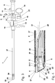
- a bipolar resectoscope 1 essentially consists of an inner shaft 2, an electrode transporter 3, a first electrode 4, a second electrode 5 and an optical system 6.
- the inner shaft 2 has an insulating insert 8 at its distal end 7 facing the patient.
- the electrode transporter 3 can be inserted into the inner shaft 2 from its proximal end 9 facing away from the distal end 7 and can be latched to the inner shaft 2.
- the electrode transporter 3 has a guide tube 10, at the proximal end 11 facing the surgeon a connector 12 for connecting the optics 6, which is guided in the guide tube 10, is arranged.
- the electrode transporter 3 has a finger grip 13 and a connection cone 14 located in the distal direction, which the electrode transporter 3 can be locked with a main body 15 forming the proximal end of the inner shaft 2.
- a longitudinally displaceable sliding body 16 is mounted on the guide tube 10.
- the sliding body 16 is connected to the connecting piece 12 via a resilient joint 17 and can be pressed against the spring force of the joint 17 in the direction of the finger grip 13 via a thumb ring 18.
- the sliding body 16 has a receiving opening for receiving a proximal end 19 of the first electrode 4.
- the sliding body 16 has a guide channel 20, with which the sliding body 16 is guided on the guide tube 10, the longitudinal axis 21 of the guide tube 10 coinciding with the longitudinal axis of the guide channel 20.
- the sliding body 16 has a plug receptacle 22 for a plug, not shown, which can be connected at an instrument-side end of a high-frequency cable to a first connection of a high-frequency generator, also not shown. Accordingly, the second electrode 5 can be connected at its proximal end to a second connection of the high-frequency generator.
- the first electrode 4 is forked in a known manner at its distal end 23 and has approximately parallel to the longitudinal axis 21 two parallel loop guide tubes 24, between which a semicircular cutting loop 25 is stretched.
- the cutting loop 25 is bent back in a proximal direction and forms an acute angle 26 with respect to the longitudinal axis 21 or with respect to the loop guide tubes 24.
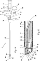
- the insulating insert 8 has at its distal end 27 a circumferential, electrically conductive electrode surface 29 which is exposed transversely to the longitudinal axis 28 of the inner shaft 2 and which is connected on the inside 30 of the insulating insert to the distal end 31 of the second electrode 5 via an intermediate piece 32.
- the first electrode 4 is designed as an active cutting electrode, while the exposed electrode surface 29 of the insulating insert 8 is designed as a passive neutral electrode for returning the high-frequency current.
- the exposed electrode surface 29 of the insulating insert 8 is arranged on the outside 34 of the insulating insert 8 radially facing away from the longitudinal axis 33, the exposed electrode surface 29 of the insulating insert 8 being electrically insulated inwards, ie towards the inside 30 of the insulating insert 8.
- the electrode surface 29 on the roof-shaped upper side of the insulating insert 8 is wider and therefore narrower in the area of the lower side in the area of the cutting edge 36.
- the exposed electrode surface 29 of the insulating insert 8 is annular. That is, the electrode surface 29 is of equal width both in the roof area and in the area of the cutting edge 36.
- the exposed electrode surface 29 of the insulating insert 8 is arranged on the inside 30 of the insulating insert 8 radially facing the longitudinal axis 33, the exposed electrode surface 29 of the insulating insert 8 being electrically insulated radially towards the outside.
- the exposed electrode surfaces 29 are arranged insulated in the longitudinal direction on the one hand towards the distal end 27 of the insulating insert 8 and on the other hand towards the free or distal end 7 of the inner shaft.
- the insulating insert (8) is inserted with its proximal end 35 into the distal end 7 of the inner shaft 2.
- the intermediate piece 32 connected to the electrode surface 29 is connected to the distal end 31 of the second electrode 5 via a plug connection 40.
- the Plug connection 40 consists of a plug contact 41 which protrudes from the proximal end 35 of the insulating insert 8 and is electrically conductively connected to the intermediate piece 32, and of a contact sleeve 42 which forms the distal end 31 of the second electrode 5 and which is the free end of the Plug contact 41 takes.
- the insulating insert 8 is formed, for example, from a plastic, the exposed electrode surface 29 being made from a metallic material.
- the insulating insert 8 can, however, also be formed from a non-conductive ceramic, the exposed electrode surface 29 being formed from a metallized ceramic.
- the inner shaft 2 is arranged in an outer shaft 37, the two shafts 2, 37 forming a continuous rinsing shaft with continuous rinsing.
- the distal end 38 of the outer shaft 37 is set back in the proximal direction in the region of the insulating insert 8, that is to say spaced, relative to the distal end 27 of the insulating insert 8.
- the outer shaft 37 has a plurality of reflux openings 39 at its distal end 38.
- both the inner shaft 2 and the outer shaft 37 are formed from an electrically conductive material.
- the passive electrode transporter shown in the exemplary embodiment can also be designed as an active electrode transporter known to the person skilled in the art.
- the person skilled in the art for coagulating tissue can replace the cutting electrode 4 with a coagulation electrode known to the person skilled in the art.
- the second electrode 5 arranged in the inner shaft 2 does not have to be arranged at the bottom in the region of the cutting edge 36 or at the top, as shown in the exemplary embodiments. The person skilled in the art will consider them with regard to the arrangement of the optics and the electrode guide tube (not shown) of the electrode transporter 3 at a suitable point in the Arrange inner shaft 2.
Landscapes
- Health & Medical Sciences (AREA)
- Life Sciences & Earth Sciences (AREA)
- Surgery (AREA)
- Engineering & Computer Science (AREA)
- General Health & Medical Sciences (AREA)
- Veterinary Medicine (AREA)
- Public Health (AREA)
- Physics & Mathematics (AREA)
- Nuclear Medicine, Radiotherapy & Molecular Imaging (AREA)
- Animal Behavior & Ethology (AREA)
- Biomedical Technology (AREA)
- Heart & Thoracic Surgery (AREA)
- Medical Informatics (AREA)
- Molecular Biology (AREA)
- Plasma & Fusion (AREA)
- Otolaryngology (AREA)
- Biophysics (AREA)
- Radiology & Medical Imaging (AREA)
- Pathology (AREA)
- Optics & Photonics (AREA)
- Surgical Instruments (AREA)
Claims (8)
- Résectoscope bipolaire (1), comprenant- une tige externe (37) constituée complètement d'un matériau électroconducteur et présentant une pluralité d'orifices de reflux (39) à son extrémité distale ,- une tige intérieure (2) disposée dans la tige externe (37) et constituée d'un matériau électroconducteur, munie d'un insert isolant (8) agencé à son extrémité distale (7) et constitué d'un matériau non électroconducteur, un reflux du liquide d'irrigation étant rendu possible via les orifices de reflux (39) de la tige externe (37) entre la tige externe (37) et la tige intérieure (2),- un transporteur d'électrode (3) pouvant être agencé dans la tige intérieure (2),- une première électrode (4) pouvant être agencée pour coulisser longitudinalement dans le transporteur d'électrode (3), laquelle peut être connectée à son extrémité proximale (19) opposée à l'extrémité distale à un premier raccordement d'un générateur de haute fréquence et qui est divisée à son extrémité distale (23) en forme de fourche et présente deux tubes parallèles de guidage d'anse (24) parallèlement à l'axe longitudinal (21), entre lesquels est tendue une anse coupante (25) semi-circulaire, et- une seconde électrode (5) pouvant être connectée à son extrémité proximale à un second raccordement au générateur de haute fréquence,où l'insert isolant (8) présente à son extrémité distale (27) une surface d'électrode (29) périphérique électroconductrice qui est dégagée transversalement par rapport à l'axe longitudinal (28) de la tige intérieure (2) et qui est connectée sur le côté intérieur (30) de l'insert isolant (8) à l'extrémité distale (31) de la seconde électrode (5);
où la surface d'électrode (29) dégagée de l'insert isolant (8) est agencée, de manière isolée, dans la direction longitudinale, d'un côté, vers l'extrémité distale (27) de l'insert isolant (8) et, de l'autre côté, vers l'extrémité libre (7) de la tige intérieure (2);
et où la surface d'électrode (29) dégagée de l'insert isolant (8) est agencée sur le côté extérieur (34) de l'insert isolant (8), opposé radialement à l'axe longitudinal (33), et est isolée électriquement vers l'intérieur. - Résectoscope bipolaire (1), comprenant- une tige externe (37) constituée complètement d'un matériau électroconducteur et présentant une pluralité d'orifices de reflux (39) à son extrémité distale,- une tige intérieure (2) pouvant être disposée dans la tige externe (37) et constituée d'un matériau électroconducteur, munie d'un insert isolant (8) agencé à son extrémité distale (7) et constitué d'un matériau non électroconducteur, un reflux du liquide d'irrigation étant rendu possible via les orifices de reflux (39) de la tige externe (37) entre la tige externe (37) et la tige intérieure (2),- un transporteur d'électrode (3) pouvant être agencé dans la tige intérieure (2),- une première électrode (4) pouvant être agencée pour coulisser longitudinalement dans le transporteur d'électrode (3), laquelle peut être connectée à son extrémité proximale (19) opposée à l'extrémité distale à un premier raccordement d'un générateur de haute fréquence et qui est divisée à son extrémité distale (23) en forme de fourche et présente deux tubes parallèles de guidage d'anse (24) parallèlement à l'axe longitudinal (21), entre lesquels est tendue une anse coupante (25) semi-circulaire, et- une seconde électrode (5) pouvant être connectée à son extrémité proximale à un second raccordement au générateur de haute fréquence,où l'insert isolant (8) présente à son extrémité distale (27) une surface d'électrode (29) périphérique électroconductrice qui est dégagée transversalement par rapport à l'axe longitudinal (28) de la tige intérieure (2) et qui est connectée sur le côté intérieur (30) de l'insert isolant (8) à l'extrémité distale (31) de la seconde électrode (5);
où la surface d'électrode (29) dégagée de l'insert isolant (8) est disposée, de manière isolée, dans la direction longitudinale, d'un côté, vers l'extrémité distale (27) de l'insert isolant (8) et, de l'autre côté, vers l'extrémité libre (7) de la tige intérieure (2);
et où la surface d'électrode (29) dégagée de l'insert isolant (8) est agencée sur le côté intérieur (30) de l'insert isolant (8), tourné radialement vers l'axe longitudinal (33), et est isolée électriquement vers l'extérieur. - Résectoscope bipolaire selon la revendication 1 ou 2,
caractérisé en ce que
la première électrode (4) est réalisée comme une électrode de résection active et la surface d'électrode (29) dégagée de l'insert isolant (8) est réalisée comme une électrode neutre passive. - Résectoscope bipolaire selon l'une des revendications 1 à 3,
caractérisé en ce que
l'insert isolant (8) est constitué d'un matériau synthétique et que la surface d'électrode (29) dégagée est constituée d'un matériau métallique. - Résectoscope bipolaire selon l'une des revendications 1 à 3,
caractérisé en ce que
l'insert isolant (8) est en céramique et que
la surface d'électrode (29) dégagée est constituée d'une céramique métallisée. - Résectoscope bipolaire selon l'une des revendications 1 à 5,
caractérisé en ce que
les deux tiges (2, 37) forment une tige d'irrigation durable à irrigation continue. - Résectoscope bipolaire selon la revendication 6,
caractérisé en ce que
l'extrémité distale (38) de la tige externe (37) est en retrait par rapport à l'extrémité distale (27) de l'insert isolant (8) dans la direction proximale dans la zone de l'insert isolant (8). - Résectoscope bipolaire selon l'une des revendications 1 à 7,
caractérisé en ce que
l'insert isolant (8) est inséré par son extrémité proximale (35) dans l'extrémité distale (7) de la tige intérieure (2) et que
l'élément intercalé (32) raccordé à la surface d'électrode (29) est connecté à l'extrémité distale (31) de la seconde électrode (5) via une connexion enfichable (40).
Applications Claiming Priority (2)
| Application Number | Priority Date | Filing Date | Title |
|---|---|---|---|
| DE102013001156.6A DE102013001156B4 (de) | 2013-01-24 | 2013-01-24 | Bipolares Resektoskop |
| PCT/EP2014/051048 WO2014114600A1 (fr) | 2013-01-24 | 2014-01-20 | Résectoscope bipolaire |
Publications (2)
| Publication Number | Publication Date |
|---|---|
| EP2948086A1 EP2948086A1 (fr) | 2015-12-02 |
| EP2948086B1 true EP2948086B1 (fr) | 2020-02-05 |
Family
ID=50073149
Family Applications (1)
| Application Number | Title | Priority Date | Filing Date |
|---|---|---|---|
| EP14703785.7A Active EP2948086B1 (fr) | 2013-01-24 | 2014-01-20 | Résectoscope bipolaire |
Country Status (4)
| Country | Link |
|---|---|
| US (1) | US20150351826A1 (fr) |
| EP (1) | EP2948086B1 (fr) |
| DE (1) | DE102013001156B4 (fr) |
| WO (1) | WO2014114600A1 (fr) |
Families Citing this family (21)
| Publication number | Priority date | Publication date | Assignee | Title |
|---|---|---|---|---|
| DE102014115487A1 (de) * | 2014-10-23 | 2016-04-28 | Olympus Winter & Ibe Gmbh | Handinstrument für chirurgische Eingriffe |
| US10004385B2 (en) * | 2015-02-27 | 2018-06-26 | Covidien Lp | Oblique tip endoscope with zero degree field angle |
| DE102015004328B4 (de) * | 2015-04-09 | 2019-05-16 | Olympus Winter & Ibe Gmbh | Transporteur und Stecker eines Resektoskopes |
| FR3036278B1 (fr) | 2015-05-20 | 2017-06-23 | Ab Medica | Dispositif pour realiser le resection d'un organe dans une cavite d'un corps vivant |
| US10869716B2 (en) | 2015-08-28 | 2020-12-22 | Covidien Lp | Powered bipolar resectoscope |
| US10383682B2 (en) | 2015-08-28 | 2019-08-20 | Covidien Lp | Powered bipolar resectoscope |
| USD820444S1 (en) * | 2016-08-12 | 2018-06-12 | Karl Storz Gmbh & Co. Kg | Resectoscope shaft for cold enucleation |
| CN107212920A (zh) * | 2017-01-23 | 2017-09-29 | 杭州安杰思医学科技有限公司 | 内窥镜用处理装置、内窥镜、及扩展支架 |
| DE102017118885B3 (de) | 2017-08-18 | 2018-12-27 | Bowa Electronic Gmbh & Co. Kg | Bipolares Resektoskop |
| DE102018127919A1 (de) | 2018-11-08 | 2020-05-14 | Karl Storz Se & Co. Kg | Elektrodenanordnung für ein bipolares Resektoskop sowie Resektoskop |
| CN113645916B (zh) * | 2019-01-28 | 2024-09-24 | 奥林巴斯株式会社 | 电极单元和内窥镜系统 |
| DE102019102839A1 (de) | 2019-02-05 | 2020-08-06 | Olympus Winter & Ibe Gmbh | Spülflüssigkeit für die Resektion |
| DE102019102841A1 (de) * | 2019-02-05 | 2020-08-06 | Olympus Winter & Ibe Gmbh | Lösbarer Isoliereinsatz zur Verwendung in einem Resektoskop |
| US11766288B2 (en) * | 2019-02-22 | 2023-09-26 | Gyrus Acmi, Inc. | Flexible bipolar sheath |
| DE102019106430A1 (de) | 2019-03-13 | 2020-09-17 | Olympus Winter & Ibe Gmbh | Elektrodeninstrument und Resektoskop mit Greiffunktion |
| US11717342B2 (en) | 2019-04-11 | 2023-08-08 | Gyrus Acmi, Inc. | Medical device |
| CN110123255B (zh) * | 2019-06-04 | 2025-01-03 | 北京大学第一医院 | 一种多功能腔道检查及治疗内镜系统 |
| DE102019132536B3 (de) * | 2019-11-29 | 2021-05-06 | Olympus Winter & Ibe Gmbh | Transporteur mit Verriegelungseinrichtung |
| DE102019135571A1 (de) * | 2019-12-20 | 2021-06-24 | Olympus Winter & Ibe Gmbh | Resektoskop mit distaler Elektrodenführung |
| DE102020118965A1 (de) * | 2020-07-17 | 2022-02-10 | Olympus Winter & Ibe Gmbh | Chirurgisches Handgerät, Isoliereinsatz für ein chirurgisches Handgerät und Verfahren zur Handhabung eines chirurgischen Handgeräts |
| JP2023548077A (ja) * | 2020-10-28 | 2023-11-15 | ユナイテッド ステイツ エンドスコピー グループ,インコーポレイテッド | 内視鏡用キャップ |
Family Cites Families (14)
| Publication number | Priority date | Publication date | Assignee | Title |
|---|---|---|---|---|
| DE2521719C2 (de) * | 1975-05-15 | 1985-06-20 | Delma, Elektro- Und Medizinische Apparatebaugesellschaft Mbh, 7200 Tuttlingen | Elektrochirurgische Vorrichtung |
| US5007908A (en) * | 1989-09-29 | 1991-04-16 | Everest Medical Corporation | Electrosurgical instrument having needle cutting electrode and spot-coag electrode |
| US6730081B1 (en) * | 1991-10-18 | 2004-05-04 | Ashvin H. Desai | Endoscopic surgical instrument |
| US5902272A (en) | 1992-01-07 | 1999-05-11 | Arthrocare Corporation | Planar ablation probe and method for electrosurgical cutting and ablation |
| US6632193B1 (en) * | 1995-06-07 | 2003-10-14 | Arthrocare Corporation | Systems and methods for electrosurgical tissue treatment |
| US6015406A (en) * | 1996-01-09 | 2000-01-18 | Gyrus Medical Limited | Electrosurgical instrument |
| EP0873087A1 (fr) | 1995-12-29 | 1998-10-28 | Microgyn, Inc. | Dispositif et procede pour electrochirurgie |
| US5925040A (en) * | 1997-06-18 | 1999-07-20 | Medical Scientific, Inc. | Electrosurgical instrument having a segmented roller electrode |
| DE10028850C1 (de) | 2000-06-16 | 2001-10-31 | Winter & Ibe Olympus | HF-resektoskopisches Instrument |
| US6827717B2 (en) | 2000-08-26 | 2004-12-07 | Olympus Winter & Ibe Gmbh | Monopolar and bipolar electrode for a urological resectoscope |
| DE10258730A1 (de) | 2002-12-06 | 2004-07-15 | Karl Storz Gmbh & Co. Kg | Bipolares medizinisches Instrument sowie elektrochirurgisches System mit einem solchen Instrument |
| US7062310B2 (en) * | 2003-10-06 | 2006-06-13 | Tyco Electronics Corporation | Catheter tip electrode assembly and method for fabricating same |
| WO2011143200A2 (fr) * | 2010-05-11 | 2011-11-17 | Electromedical Associates Llc | Dispositif électrochirurgical brasé |
| US9737362B2 (en) * | 2011-07-06 | 2017-08-22 | Boston Scientific Scimed, Inc. | Tissue cutting systems and methods |
-
2013
- 2013-01-24 DE DE102013001156.6A patent/DE102013001156B4/de active Active
-
2014
- 2014-01-20 US US14/762,957 patent/US20150351826A1/en not_active Abandoned
- 2014-01-20 EP EP14703785.7A patent/EP2948086B1/fr active Active
- 2014-01-20 WO PCT/EP2014/051048 patent/WO2014114600A1/fr not_active Ceased
Non-Patent Citations (1)
| Title |
|---|
| None * |
Also Published As
| Publication number | Publication date |
|---|---|
| DE102013001156B4 (de) | 2021-10-14 |
| EP2948086A1 (fr) | 2015-12-02 |
| DE102013001156A1 (de) | 2014-07-24 |
| WO2014114600A1 (fr) | 2014-07-31 |
| US20150351826A1 (en) | 2015-12-10 |
Similar Documents
| Publication | Publication Date | Title |
|---|---|---|
| EP2948086B1 (fr) | Résectoscope bipolaire | |
| EP1221903B1 (fr) | Resectoscope urologique avec une electrode monopolaire ou bipolaire | |
| EP0954246B1 (fr) | Dispositif pour la coagulation de tissus biologiques | |
| DE112004000844B4 (de) | Zum berührenden und Plasma-Koagulationsbetrieb geeignetes elektrochirurgisches Instrument für ein Endoskop oder einen Katheter | |
| DE69122131T2 (de) | Chirurgisches sauginstrument | |
| EP3443920B1 (fr) | Résectoscope bipolaire | |
| DE2528543A1 (de) | Resektoskop und dazugehoerige elektrode | |
| WO2001089403A1 (fr) | Systeme d'electrodes d'un instrument chirurgical | |
| EP1256325A1 (fr) | Resectoscope pour urologie avec manteau isolant | |
| EP3649974B1 (fr) | Agencement d'électrodes pour un résectoscope bipolaire et résectoscope | |
| DE102006006052B4 (de) | Hochfrequenz-Behandlungsgerät für ein Endoskop | |
| EP3838205A1 (fr) | Résectoscope à guidage distale d'électrode | |
| EP1311200A1 (fr) | Resectoscope urologique avec dispositif de mise en contact | |
| DE102007045725B4 (de) | Hochfrequenz-Inzisionsinstrument für ein Endoskop | |
| DE112013004897T5 (de) | Elektrochirurgisches Plasmagerät und System | |
| DE19850663A1 (de) | Instrument für die Hochfrequenzchirurgie | |
| EP3471642B1 (fr) | Instrument chirurgical pour la diathermie chirurgicale et accessoire pour celui-ci | |
| DE4237321C2 (de) | Instrument für die Hochfrequenzchirurgie | |
| DE102012009058B4 (de) | Bipolarer Elektrodenanschluss | |
| DE102016003177A1 (de) | Elektrode eines Resektoskopes | |
| EP3708103B1 (fr) | Instrument à électrodes et résectoscope ayant une fonction de préhension | |
| DE202013010300U1 (de) | Nadelförmiges Instrument für die Hochfrequenz-Thermotherapie | |
| DE20107176U1 (de) | Monopolare und bipolare Elektrode für ein urologisches Resektoskop | |
| DE102023129912A1 (de) | Bipolare Elektrode für ein Resektoskop sowie Resektoskop mit einer solchen bipolaren Elektrode | |
| DE19653214C2 (de) | Koagulationsvorrichtung zur Koagulation biologischer Gewebe |
Legal Events
| Date | Code | Title | Description |
|---|---|---|---|
| PUAI | Public reference made under article 153(3) epc to a published international application that has entered the european phase |
Free format text: ORIGINAL CODE: 0009012 |
|
| 17P | Request for examination filed |
Effective date: 20150820 |
|
| AK | Designated contracting states |
Kind code of ref document: A1 Designated state(s): AL AT BE BG CH CY CZ DE DK EE ES FI FR GB GR HR HU IE IS IT LI LT LU LV MC MK MT NL NO PL PT RO RS SE SI SK SM TR |
|
| AX | Request for extension of the european patent |
Extension state: BA ME |
|
| DAX | Request for extension of the european patent (deleted) | ||
| 17Q | First examination report despatched |
Effective date: 20160712 |
|
| STAA | Information on the status of an ep patent application or granted ep patent |
Free format text: STATUS: EXAMINATION IS IN PROGRESS |
|
| GRAP | Despatch of communication of intention to grant a patent |
Free format text: ORIGINAL CODE: EPIDOSNIGR1 |
|
| STAA | Information on the status of an ep patent application or granted ep patent |
Free format text: STATUS: GRANT OF PATENT IS INTENDED |
|
| INTG | Intention to grant announced |
Effective date: 20190627 |
|
| GRAJ | Information related to disapproval of communication of intention to grant by the applicant or resumption of examination proceedings by the epo deleted |
Free format text: ORIGINAL CODE: EPIDOSDIGR1 |
|
| STAA | Information on the status of an ep patent application or granted ep patent |
Free format text: STATUS: EXAMINATION IS IN PROGRESS |
|
| GRAP | Despatch of communication of intention to grant a patent |
Free format text: ORIGINAL CODE: EPIDOSNIGR1 |
|
| STAA | Information on the status of an ep patent application or granted ep patent |
Free format text: STATUS: GRANT OF PATENT IS INTENDED |
|
| INTC | Intention to grant announced (deleted) | ||
| GRAS | Grant fee paid |
Free format text: ORIGINAL CODE: EPIDOSNIGR3 |
|
| INTG | Intention to grant announced |
Effective date: 20191118 |
|
| GRAA | (expected) grant |
Free format text: ORIGINAL CODE: 0009210 |
|
| STAA | Information on the status of an ep patent application or granted ep patent |
Free format text: STATUS: THE PATENT HAS BEEN GRANTED |
|
| AK | Designated contracting states |
Kind code of ref document: B1 Designated state(s): AL AT BE BG CH CY CZ DE DK EE ES FI FR GB GR HR HU IE IS IT LI LT LU LV MC MK MT NL NO PL PT RO RS SE SI SK SM TR |
|
| REG | Reference to a national code |
Ref country code: GB Ref legal event code: FG4D Free format text: NOT ENGLISH |
|
| REG | Reference to a national code |
Ref country code: AT Ref legal event code: REF Ref document number: 1229392 Country of ref document: AT Kind code of ref document: T Effective date: 20200215 |
|
| REG | Reference to a national code |
Ref country code: DE Ref legal event code: R096 Ref document number: 502014013556 Country of ref document: DE |
|
| REG | Reference to a national code |
Ref country code: IE Ref legal event code: FG4D Free format text: LANGUAGE OF EP DOCUMENT: GERMAN |
|
| REG | Reference to a national code |
Ref country code: CH Ref legal event code: EP |
|
| REG | Reference to a national code |
Ref country code: NL Ref legal event code: FP |
|
| PG25 | Lapsed in a contracting state [announced via postgrant information from national office to epo] |
Ref country code: FI Free format text: LAPSE BECAUSE OF FAILURE TO SUBMIT A TRANSLATION OF THE DESCRIPTION OR TO PAY THE FEE WITHIN THE PRESCRIBED TIME-LIMIT Effective date: 20200205 Ref country code: PT Free format text: LAPSE BECAUSE OF FAILURE TO SUBMIT A TRANSLATION OF THE DESCRIPTION OR TO PAY THE FEE WITHIN THE PRESCRIBED TIME-LIMIT Effective date: 20200628 Ref country code: NO Free format text: LAPSE BECAUSE OF FAILURE TO SUBMIT A TRANSLATION OF THE DESCRIPTION OR TO PAY THE FEE WITHIN THE PRESCRIBED TIME-LIMIT Effective date: 20200505 Ref country code: RS Free format text: LAPSE BECAUSE OF FAILURE TO SUBMIT A TRANSLATION OF THE DESCRIPTION OR TO PAY THE FEE WITHIN THE PRESCRIBED TIME-LIMIT Effective date: 20200205 |
|
| REG | Reference to a national code |
Ref country code: LT Ref legal event code: MG4D |
|
| PG25 | Lapsed in a contracting state [announced via postgrant information from national office to epo] |
Ref country code: IS Free format text: LAPSE BECAUSE OF FAILURE TO SUBMIT A TRANSLATION OF THE DESCRIPTION OR TO PAY THE FEE WITHIN THE PRESCRIBED TIME-LIMIT Effective date: 20200605 Ref country code: SE Free format text: LAPSE BECAUSE OF FAILURE TO SUBMIT A TRANSLATION OF THE DESCRIPTION OR TO PAY THE FEE WITHIN THE PRESCRIBED TIME-LIMIT Effective date: 20200205 Ref country code: LV Free format text: LAPSE BECAUSE OF FAILURE TO SUBMIT A TRANSLATION OF THE DESCRIPTION OR TO PAY THE FEE WITHIN THE PRESCRIBED TIME-LIMIT Effective date: 20200205 Ref country code: GR Free format text: LAPSE BECAUSE OF FAILURE TO SUBMIT A TRANSLATION OF THE DESCRIPTION OR TO PAY THE FEE WITHIN THE PRESCRIBED TIME-LIMIT Effective date: 20200506 Ref country code: BG Free format text: LAPSE BECAUSE OF FAILURE TO SUBMIT A TRANSLATION OF THE DESCRIPTION OR TO PAY THE FEE WITHIN THE PRESCRIBED TIME-LIMIT Effective date: 20200505 Ref country code: HR Free format text: LAPSE BECAUSE OF FAILURE TO SUBMIT A TRANSLATION OF THE DESCRIPTION OR TO PAY THE FEE WITHIN THE PRESCRIBED TIME-LIMIT Effective date: 20200205 |
|
| PG25 | Lapsed in a contracting state [announced via postgrant information from national office to epo] |
Ref country code: LT Free format text: LAPSE BECAUSE OF FAILURE TO SUBMIT A TRANSLATION OF THE DESCRIPTION OR TO PAY THE FEE WITHIN THE PRESCRIBED TIME-LIMIT Effective date: 20200205 Ref country code: ES Free format text: LAPSE BECAUSE OF FAILURE TO SUBMIT A TRANSLATION OF THE DESCRIPTION OR TO PAY THE FEE WITHIN THE PRESCRIBED TIME-LIMIT Effective date: 20200205 Ref country code: SM Free format text: LAPSE BECAUSE OF FAILURE TO SUBMIT A TRANSLATION OF THE DESCRIPTION OR TO PAY THE FEE WITHIN THE PRESCRIBED TIME-LIMIT Effective date: 20200205 Ref country code: DK Free format text: LAPSE BECAUSE OF FAILURE TO SUBMIT A TRANSLATION OF THE DESCRIPTION OR TO PAY THE FEE WITHIN THE PRESCRIBED TIME-LIMIT Effective date: 20200205 Ref country code: EE Free format text: LAPSE BECAUSE OF FAILURE TO SUBMIT A TRANSLATION OF THE DESCRIPTION OR TO PAY THE FEE WITHIN THE PRESCRIBED TIME-LIMIT Effective date: 20200205 Ref country code: RO Free format text: LAPSE BECAUSE OF FAILURE TO SUBMIT A TRANSLATION OF THE DESCRIPTION OR TO PAY THE FEE WITHIN THE PRESCRIBED TIME-LIMIT Effective date: 20200205 Ref country code: CZ Free format text: LAPSE BECAUSE OF FAILURE TO SUBMIT A TRANSLATION OF THE DESCRIPTION OR TO PAY THE FEE WITHIN THE PRESCRIBED TIME-LIMIT Effective date: 20200205 Ref country code: SK Free format text: LAPSE BECAUSE OF FAILURE TO SUBMIT A TRANSLATION OF THE DESCRIPTION OR TO PAY THE FEE WITHIN THE PRESCRIBED TIME-LIMIT Effective date: 20200205 |
|
| REG | Reference to a national code |
Ref country code: DE Ref legal event code: R097 Ref document number: 502014013556 Country of ref document: DE |
|
| PLBE | No opposition filed within time limit |
Free format text: ORIGINAL CODE: 0009261 |
|
| STAA | Information on the status of an ep patent application or granted ep patent |
Free format text: STATUS: NO OPPOSITION FILED WITHIN TIME LIMIT |
|
| 26N | No opposition filed |
Effective date: 20201106 |
|
| PG25 | Lapsed in a contracting state [announced via postgrant information from national office to epo] |
Ref country code: IT Free format text: LAPSE BECAUSE OF FAILURE TO SUBMIT A TRANSLATION OF THE DESCRIPTION OR TO PAY THE FEE WITHIN THE PRESCRIBED TIME-LIMIT Effective date: 20200205 |
|
| PG25 | Lapsed in a contracting state [announced via postgrant information from national office to epo] |
Ref country code: SI Free format text: LAPSE BECAUSE OF FAILURE TO SUBMIT A TRANSLATION OF THE DESCRIPTION OR TO PAY THE FEE WITHIN THE PRESCRIBED TIME-LIMIT Effective date: 20200205 Ref country code: PL Free format text: LAPSE BECAUSE OF FAILURE TO SUBMIT A TRANSLATION OF THE DESCRIPTION OR TO PAY THE FEE WITHIN THE PRESCRIBED TIME-LIMIT Effective date: 20200205 |
|
| PG25 | Lapsed in a contracting state [announced via postgrant information from national office to epo] |
Ref country code: MC Free format text: LAPSE BECAUSE OF FAILURE TO SUBMIT A TRANSLATION OF THE DESCRIPTION OR TO PAY THE FEE WITHIN THE PRESCRIBED TIME-LIMIT Effective date: 20200205 |
|
| REG | Reference to a national code |
Ref country code: CH Ref legal event code: PL |
|
| PG25 | Lapsed in a contracting state [announced via postgrant information from national office to epo] |
Ref country code: LU Free format text: LAPSE BECAUSE OF NON-PAYMENT OF DUE FEES Effective date: 20210120 |
|
| REG | Reference to a national code |
Ref country code: BE Ref legal event code: MM Effective date: 20210131 |
|
| PG25 | Lapsed in a contracting state [announced via postgrant information from national office to epo] |
Ref country code: LI Free format text: LAPSE BECAUSE OF NON-PAYMENT OF DUE FEES Effective date: 20210131 Ref country code: CH Free format text: LAPSE BECAUSE OF NON-PAYMENT OF DUE FEES Effective date: 20210131 |
|
| PG25 | Lapsed in a contracting state [announced via postgrant information from national office to epo] |
Ref country code: BE Free format text: LAPSE BECAUSE OF NON-PAYMENT OF DUE FEES Effective date: 20210131 |
|
| PG25 | Lapsed in a contracting state [announced via postgrant information from national office to epo] |
Ref country code: HU Free format text: LAPSE BECAUSE OF FAILURE TO SUBMIT A TRANSLATION OF THE DESCRIPTION OR TO PAY THE FEE WITHIN THE PRESCRIBED TIME-LIMIT; INVALID AB INITIO Effective date: 20140120 |
|
| P01 | Opt-out of the competence of the unified patent court (upc) registered |
Effective date: 20230517 |
|
| PG25 | Lapsed in a contracting state [announced via postgrant information from national office to epo] |
Ref country code: CY Free format text: LAPSE BECAUSE OF FAILURE TO SUBMIT A TRANSLATION OF THE DESCRIPTION OR TO PAY THE FEE WITHIN THE PRESCRIBED TIME-LIMIT Effective date: 20200205 |
|
| PGFP | Annual fee paid to national office [announced via postgrant information from national office to epo] |
Ref country code: NL Payment date: 20240123 Year of fee payment: 11 |
|
| PGFP | Annual fee paid to national office [announced via postgrant information from national office to epo] |
Ref country code: IE Payment date: 20240118 Year of fee payment: 11 |
|
| PGFP | Annual fee paid to national office [announced via postgrant information from national office to epo] |
Ref country code: AT Payment date: 20240118 Year of fee payment: 11 |
|
| PG25 | Lapsed in a contracting state [announced via postgrant information from national office to epo] |
Ref country code: MK Free format text: LAPSE BECAUSE OF FAILURE TO SUBMIT A TRANSLATION OF THE DESCRIPTION OR TO PAY THE FEE WITHIN THE PRESCRIBED TIME-LIMIT Effective date: 20200205 |
|
| PGFP | Annual fee paid to national office [announced via postgrant information from national office to epo] |
Ref country code: GB Payment date: 20240124 Year of fee payment: 11 |
|
| PGFP | Annual fee paid to national office [announced via postgrant information from national office to epo] |
Ref country code: FR Payment date: 20240124 Year of fee payment: 11 |
|
| PG25 | Lapsed in a contracting state [announced via postgrant information from national office to epo] |
Ref country code: MT Free format text: LAPSE BECAUSE OF FAILURE TO SUBMIT A TRANSLATION OF THE DESCRIPTION OR TO PAY THE FEE WITHIN THE PRESCRIBED TIME-LIMIT Effective date: 20200205 |
|
| REG | Reference to a national code |
Ref country code: NL Ref legal event code: MM Effective date: 20250201 |
|
| REG | Reference to a national code |
Ref country code: AT Ref legal event code: MM01 Ref document number: 1229392 Country of ref document: AT Kind code of ref document: T Effective date: 20250120 |
|
| GBPC | Gb: european patent ceased through non-payment of renewal fee |
Effective date: 20250120 |
|
| PG25 | Lapsed in a contracting state [announced via postgrant information from national office to epo] |
Ref country code: NL Free format text: LAPSE BECAUSE OF NON-PAYMENT OF DUE FEES Effective date: 20250201 |
|
| PG25 | Lapsed in a contracting state [announced via postgrant information from national office to epo] |
Ref country code: GB Free format text: LAPSE BECAUSE OF NON-PAYMENT OF DUE FEES Effective date: 20250120 |
|
| PG25 | Lapsed in a contracting state [announced via postgrant information from national office to epo] |
Ref country code: FR Free format text: LAPSE BECAUSE OF NON-PAYMENT OF DUE FEES Effective date: 20250131 Ref country code: AT Free format text: LAPSE BECAUSE OF NON-PAYMENT OF DUE FEES Effective date: 20250120 |
|
| PG25 | Lapsed in a contracting state [announced via postgrant information from national office to epo] |
Ref country code: TR Free format text: LAPSE BECAUSE OF FAILURE TO SUBMIT A TRANSLATION OF THE DESCRIPTION OR TO PAY THE FEE WITHIN THE PRESCRIBED TIME-LIMIT Effective date: 20200205 |
|
| PG25 | Lapsed in a contracting state [announced via postgrant information from national office to epo] |
Ref country code: IE Free format text: LAPSE BECAUSE OF NON-PAYMENT OF DUE FEES Effective date: 20250120 |
|
| PGFP | Annual fee paid to national office [announced via postgrant information from national office to epo] |
Ref country code: DE Payment date: 20251208 Year of fee payment: 13 |