EP2948200B1 - Fluid waste collection and disposal method - Google Patents
Fluid waste collection and disposal method Download PDFInfo
- Publication number
- EP2948200B1 EP2948200B1 EP14743665.3A EP14743665A EP2948200B1 EP 2948200 B1 EP2948200 B1 EP 2948200B1 EP 14743665 A EP14743665 A EP 14743665A EP 2948200 B1 EP2948200 B1 EP 2948200B1
- Authority
- EP
- European Patent Office
- Prior art keywords
- reservoir
- fluid
- cleaning solution
- valve
- negative pressure
- Prior art date
- Legal status (The legal status is an assumption and is not a legal conclusion. Google has not performed a legal analysis and makes no representation as to the accuracy of the status listed.)
- Active
Links
Images


Classifications
-
- A—HUMAN NECESSITIES
- A61—MEDICAL OR VETERINARY SCIENCE; HYGIENE
- A61M—DEVICES FOR INTRODUCING MEDIA INTO, OR ONTO, THE BODY; DEVICES FOR TRANSDUCING BODY MEDIA OR FOR TAKING MEDIA FROM THE BODY; DEVICES FOR PRODUCING OR ENDING SLEEP OR STUPOR
- A61M1/00—Suction or pumping devices for medical purposes; Devices for carrying-off, for treatment of, or for carrying-over, body-liquids; Drainage systems
- A61M1/60—Containers for suction drainage, adapted to be used with an external suction source
- A61M1/63—Containers for suction drainage, adapted to be used with an external suction source with means for emptying the suction container, e.g. by interrupting suction
- A61M1/631—Emptying the suction container without interrupting suction
-
- F—MECHANICAL ENGINEERING; LIGHTING; HEATING; WEAPONS; BLASTING
- F15—FLUID-PRESSURE ACTUATORS; HYDRAULICS OR PNEUMATICS IN GENERAL
- F15D—FLUID DYNAMICS, i.e. METHODS OR MEANS FOR INFLUENCING THE FLOW OF GASES OR LIQUIDS
- F15D1/00—Influencing flow of fluids
- F15D1/002—Influencing flow of fluids by influencing the boundary layer
-
- B—PERFORMING OPERATIONS; TRANSPORTING
- B08—CLEANING
- B08B—CLEANING IN GENERAL; PREVENTION OF FOULING IN GENERAL
- B08B3/00—Cleaning by methods involving the use or presence of liquid or steam
- B08B3/04—Cleaning involving contact with liquid
-
- A—HUMAN NECESSITIES
- A61—MEDICAL OR VETERINARY SCIENCE; HYGIENE
- A61M—DEVICES FOR INTRODUCING MEDIA INTO, OR ONTO, THE BODY; DEVICES FOR TRANSDUCING BODY MEDIA OR FOR TAKING MEDIA FROM THE BODY; DEVICES FOR PRODUCING OR ENDING SLEEP OR STUPOR
- A61M1/00—Suction or pumping devices for medical purposes; Devices for carrying-off, for treatment of, or for carrying-over, body-liquids; Drainage systems
- A61M1/88—Draining devices having means for processing the drained fluid, e.g. an absorber
- A61M1/882—Draining devices provided with means for releasing antimicrobial or gelation agents in the drained fluid
-
- Y—GENERAL TAGGING OF NEW TECHNOLOGICAL DEVELOPMENTS; GENERAL TAGGING OF CROSS-SECTIONAL TECHNOLOGIES SPANNING OVER SEVERAL SECTIONS OF THE IPC; TECHNICAL SUBJECTS COVERED BY FORMER USPC CROSS-REFERENCE ART COLLECTIONS [XRACs] AND DIGESTS
- Y10—TECHNICAL SUBJECTS COVERED BY FORMER USPC
- Y10T—TECHNICAL SUBJECTS COVERED BY FORMER US CLASSIFICATION
- Y10T137/00—Fluid handling
- Y10T137/0318—Processes
- Y10T137/0396—Involving pressure control
Definitions
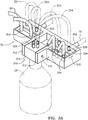
- An o-ring may be provided on the underside of the door 328 around the openings of the door nipples 326 to provide a fluid-tight connection between the door nipples 326 and the suction ports 304.
- a switch (not shown) may be provided in the hanger 310 such that when the block 314 and bottle 28 are inverted, a signal is generated permitting the cleaning process to continue.
- one or more suction ports 304 may be provided in the face of the panel 16 which connect to the fluid inlet line 70.
- the suction hoses 80 (and/or filter) may be connected directly to the panel suction ports 304 (see FIG. 10 ).
- the cleaning solution tubes 324 may be connected directly to the suction ports 304 after removal of the suction hoses 80 from the panel suction ports 304.
- the system 10 includes a programmable logic controller (“PLC”) (not shown) which interfaces with the touch screen display 20 and other circuitry.
- PLC programmable logic controller
- the circuitry and associated programming for the PLC for providing the features and performing the functions described below in connection with the "Fluid Collection and Disposal Process” and “Cleaning Cycle Process” would be readily understood and recognized by those skilled in the art and therefore further discussion on the circuitry is not warranted. Rather than using a PLC and associated circuitry, it should be appreciated that solid state circuitry could be utilized which could further reduce the total size of system 10, if desired, as well as provide additional desired functionality.
- the System Run Time indicator 202 indicates the time passed, preferably displayed in hours, minutes and seconds, since pressing the Start Suction selection 210.
- the Table Suction indicator 204 indicates the vacuum or negative pressure, preferably in inches or mm Hg, at the suction ports 304 which is controlled by the vacuum adjust controller 24 on the front panel 16. If multiple suctions ports 304 are provided, a separate Table Suction indicator 204 may be provided to indicate the negative pressure at each suction port.
- the Source Suction display 206 indicates, the suction provided by the facility's vacuum system, preferably in inches or mm Hg, to which the vacuum port 32 is connected.
- the status/information indicator 208 provides information to the operator such as the current operation selection, system status or any alarm conditions.
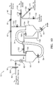
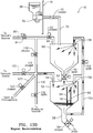
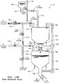
- the vacuum line 90 extends between a regulated vacuum source (not shown) and a vacuum port 94 of the first reservoir 50. Disposed along the vacuum line 90 is the regulator 91 and the electronically controllable vacuum line valve 92, such as a solenoid or motor driven valve.
- the auxiliary line 100 branches off the vacuum line 90 and connects to an auxiliary port 104 of the second reservoir 52. Disposed along the auxiliary line 100 is the electronically controllable auxiliary line valve 102, such as a solenoid or motor driven valve.
- the fluid transfer valve 56 and the fluid discharge mechanism 59 comprise electronically controllable valves as previously described.
- the embodiment of FIG. 5 also includes a vacuum assist line 110 connecting a vacuum assist source (not shown) to the auxiliary line 100.
- a vacuum assist line 110 Disposed along the vacuum assist line 110 is a an electronically controllable vacuum assist line valve 112, such as a solenoid or motor driven valve.
- a vent line 120 which vents to atmosphere also connects to the auxiliary line 100.
- an electronically controllable vent line valve 122 such as a solenoid or motor driven valve.
- a pressure line 130 connects a pressure source, such as an air compressor (not shown) to the auxiliary line 100. Disposed along the pressure line 130 is an electronically controllable pressure line valve 132 such as a solenoid or motor driven valve. Also in the embodiment of FIG. 5 , the recirculation line 150 fluidly connects the first and second reservoirs 50, 52 and an electronically controllable valve 152 is disposed along the recirculation line 150 to control the flow of cleaning solution during the Cleaning Cycle Process.
- a pressure source such as an air compressor (not shown)
- an electronically controllable pressure line valve 132 such as a solenoid or motor driven valve.
- the recirculation line 150 fluidly connects the first and second reservoirs 50, 52 and an electronically controllable valve 152 is disposed along the recirculation line 150 to control the flow of cleaning solution during the Cleaning Cycle Process.
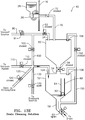
- FIG. 7 is likewise substantially similar to FIG. 5 except that the vacuum assist and pressure source and associated lines 110, 130 and valves 112, 132 are eliminated.
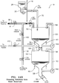
- FIG. 8 is substantially the same as FIG. 5 , except that a recirculation pump 160 rather than the recirculation line valve 152 is used to control the flow of cleaning solution during the Cleaning Cycle Process.
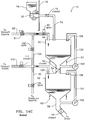
- the fluid transfer valve 56 and fluid discharge mechanism 59 comprise check valves. Additionally, the vent line 120 and associated vent line valve 122 are eliminated. Also in the embodiment of FIG. 9 , separate recirculation lines 150 and separate recirculation pumps 160 are used to control the flow of cleaning solution during the Cleaning Cycle Process.
- FIG. 10 is substantially the same as the embodiment of FIG. 5 , except that the first and second reservoirs 50, 52 are arranged in a side-by-side relationship as opposed to a stacked relationship.
- the first and second reservoirs 50, 52 and associated components in the various embodiments are constructed of suitable material of sufficient thickness to safely withstand the negative pressures typically used for the vacuum systems of a medical facility, which typically are not greater than 25 inches (635 mm) of mercury (Hg). Additionally, the reservoirs and associated components are preferably designed to withstand positive pressures of up to 20 psi.
- a suitable material for the reservoirs may be transparent acrylic to allow the surgeon or other medical personnel to view the aspirated fluid as it is collected for assessing its color or other characteristics.
- the first and second reservoirs 50, 52 are preferably configured with sloped bottom walls to permit the complete drainage of collected waste fluid as discussed in detail later.
- a light strip (not shown) which may comprise a plurality of white light emitting diodes (LEDs) may be disposed behind the reservoirs 50, 52 to back-light the fluid in the reservoirs 50, 52 so it can be better viewed through the viewing window 22 in the front panel 16.
- LEDs white light emitting diodes
- the LEDs are preferably caused to light and flash to visually indicate an alarm condition.
- the PLC is preferably programmed to flash an error message on the touch screen display 20.
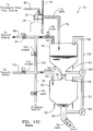
- the initial "Fluid In” phase is initiated by the PLC generating a signal to open the electronically controllable fluid transfer valve 56 and auxiliary line valve 102 permitting communication of the vacuum source with the second reservoir 52, and to the first reservoir 50 through the open fluid transfer valve 56.
- the electronically controllable valves of the fluid discharge mechanism 59, vacuum assist line valve 112, the vent line valve 122 and the pressure line valve 132 are in the closed position. Because the fluid transfer valve 56 is in the open position, it should be appreciated that the first and second reservoirs 50, 52 will have the same negative pressure due to the air being evacuated (as indicated by the arrows) by the vacuum source.
- the negative pressure inside the reservoirs 50, 52 creates suction through the inlet line 70, which overcomes the bias of the normally closed inlet line check valve 72, such that suction is provided to the suction ports 304 of the manifold 30.
- the operator attaches the suction hose 80 to the suction ports 304. If a filter is used, the filter is connected to the suction ports 304 and the suction hoses are connected to inlets on the filter.
- the distal end of the suction hose 80 includes an end effector (not shown) which typically includes a regulator for controlling the amount of suction through the end effector.
- the operator may also adjust the amount of Table Suction 204 using the vacuum adjust controller(s) 24.
- the end effector on the suction hose 80 is placed in contact with fluid, fluid is drawn through the suction hose 80 and into the first reservoir 50 and then into the second reservoir 52 due to the fluid transfer valve 56 being open.
- the fluid entering the first and/or second reservoirs 50, 52 is preferably visible through the window 22 in the front panel.
- a light strip may be used to back-light the aspirated fluid entering in the reservoirs so it can be better viewed by the operator.
- the first reservoir remains under negative pressure via the open vacuum line valve 92, such that communication of the vacuum source with the first reservoir is not interrupted.
- a signal is generated to cause the PLC to open the vent line valve 122.
- air enters the second reservoir 52 to relieving the negative pressure until it is brought to atmospheric pressure.
- the volume of fluid in the second reservoir 52 is then determined or otherwise measured and recorded by the fluid measuring system 400 as described later.
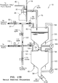
- the fluid collection and disposal process of the embodiment of FIG. 6 is substantially similar to that of the embodiment of FIG. 5 , except that because the vacuum assist has been eliminated in the embodiment of FIG. 6 , after the fluid is drained from the second reservoir 52, the "Second Reservoir Preparation" phase is performed by the PLC generating a signal to open the auxiliary line valve 102 to equalize the negative pressure in the second reservoir 52 with the negative pressure in the first reservoir 50 before the fluid transfer valve 56 is opened to begin repeating the "Fluid In" phase.
- the fluid collection and disposal process of the embodiment of FIG. 7 is substantially similar to that of the embodiment of FIG. 6 , except that because the vacuum assist and the pressure source have been eliminated in the embodiment of FIG. 7 , the fluid is drained from the second reservoir 52 during the "Drain” phase via gravity alone and therefore the vent line valve 122 remains open until the fluid is drained from the second reservoir.
- the PLC When the fluid is drained from the second reservoir 52, the PLC generates a signal to close the vent line valve 122 and to initiate the "Second Reservoir Preparation" phase by opening the auxiliary line valve 102 to equalize the negative pressure in the second reservoir 52 with the negative pressure in the first reservoir 50 before the fluid transfer valve 56 is opened to begin repeating the "Fluid In" phase.
- FIG. 8 The fluid collection and disposal process of the embodiment of FIG. 8 is the same as described in connection with FIGs. 11A-11D , but the Cleaning Cycle Process will vary as described later.
- the fluid collection and disposal process of the embodiment of FIG. 10 is substantially the same as that described in connection with the embodiment of FIG. 5 except that rather than utilizing a ball float type volume sensor, the embodiment of FIG. 10 shows the fluid sensor 60 as being a flow meter rather than a float-type sensor.
- FIGs. 12A-12D are made to describe the fluid collection and disposal process for the embodiment of FIG. 9 .
- the initial "Fluid In” phase is initiated by the PLC generating a signal to open the auxiliary line valve 102 and/or the vacuum assist line valve 112 permitting communication of the vacuum source and/or vacuum assist source with the second reservoir 52 (as indicated by the arrows).
- the fluid transfer valve 56 and fluid discharge mechanism 59 comprise check valves which are not electronically controllable by the PLC. Because the fluid transfer check valve 56 is biased in the normally closed position, the fluid transfer check valve 56 will remain closed until the negative pressure in the second reservoir sufficiently exceeds the negative pressure in the first reservoir to overcome the bias forcing the fluid transfer check valve 56 to open. During the initial Fluid In phase, the vacuum line valve 92 remains closed and thus, the first reservoir is not in communication with the vacuum source. As a result, the fluid transfer check valve 56 is forced to open when the auxiliary line valve 102 and/or vacuum assist line valve 112 are opened because only the second reservoir is in communication with the vacuum source and/or vacuum assist source.
- the first reservoir With the fluid transfer check valve 56 open, the first reservoir is now in communication with the vacuum source.
- the negative pressure inside the reservoirs 50, 52 creates suction through the inlet line 70, which overcomes the bias of the normally closed inlet line check valve 72, such that suction is provided to the suction ports 304 of the manifold 30.
- the operator attaches the suction hose 80 to the suction ports 304. If a filter is used, the filter is connected to the suction ports 304 and the suction hoses are connected to inlets on the filter.
- the distal end of the suction hose 80 includes an end effector (not shown) which typically includes a regulator for controlling the amount of suction through the end effector.
- the operator may also adjust the amount of Table Suction 204 using the vacuum adjust controller(s) 24.
- the end effector on the suction hose 80 is placed in contact with fluid, fluid is drawn through the suction hose 80 and into the first reservoir 50 and then into the second reservoir 52 due to the fluid transfer valve 56 being open.
- the fluid entering the first and/or second reservoirs 50, 52 is preferably visible through the window 22 in the front panel.
- a light strip may be used to back-light the aspirated fluid entering in the reservoirs so it can be better viewed by the operator.
- the "Second Reservoir Preparation" phase is initiated as depicted in FIG. 12D by the PLC generating a signal to cause the pressure line valve 132 to close, and to cause the auxiliary line valve 102 and/or vacuum assist line valve 112 to open to equalize the negative pressure in the second reservoir with the negative pressure of the first reservoir.
- the check valve of the fluid discharge mechanism 59 returns to its normally closed position.
- the negative pressure in the second reservoir is increased (or the negative pressure in the first reservoir is caused to slightly bleed off via the PLC generating a signal to cause the regulator 91 to open thereby reducing the negative pressure in the first reservoir) until there is a slight pressure differential between the second reservoir and first reservoir sufficient to overcome the bias of the fluid transfer check valve 56 causing it to open, permitting the fluid being collected in the first reservoir to again flow into the second reservoir 52 thereby repeating the "Fluid In” phase as depicted in FIG. 12A , except that the vacuum line valve 92 remains open until the procedure is completed and Stop Suction 212 is selected on the touch pad.
- the "Fluid In", “Relief and Measure", “Drain” and “Second Reservoir Preparation” phases as depicted in FIGs. 12A-12D are repeated as necessary until the medical procedure is completed.
- the volume of the first reservoir 50 has sufficient capacity so that it does not fill faster than is required to complete the "Relief and Measure", “Drain” and “Second Reservoir Preparation” phases.
- a fluid sensor may be disposed to monitor the fluid level, volume or mass in the first reservoir 50 similar to the fluid sensor 60 for monitoring the second reservoir to generate signals to trigger different phases of the fluid collection and disposal process and/or to trigger an emergency shut-off of the vacuum line valve 92 if fluid in the first reservoir 50 reaches a predetermined level to prevent fluid from being drawn into the main vacuum line 90 in the event of a malfunction.
- FIGs. 13A-13E correspond to the embodiment of FIG. 5 .
- FIGs. 13A-13E correspond to the embodiment of FIG. 5 .
- FIGs. 14A-14F A more detailed discussion of the cleaning processes is provided for the embodiment of FIG. 9 with reference to FIGs. 14A-14F in view of the structural and functional difference of the embodiment of FIG. 9 as compared to the other embodiments.
- the negative pressure inside the reservoirs 50, 52 creates suction through the inlet line 70, which overcomes the bias of the normally closed inlet line check valve 72, such that the cleaning solution is drawn into the first reservoir 50, which then flows into the second reservoir through the open fluid transfer valve 56.
- a vacuum powered cleaning cycle may be used whereby, instead of using the pressure source to force the cleaning solution through the recirculation lines 150, a signal may be generated to cause the vacuum line valve 92 and auxiliary line valve 102 to open which will draw the cleaning solution through the recirculation lines 150 and nozzles 156 to spray the reservoir sidewalls.
- FIGs. 14A-14F are made to describe the Cleaning Cycle Process for the embodiment of FIG. 9 .
- the fluid transfer valve 56 and fluid discharge mechanism 59 comprise check valves which are not electronically controllable by the PLC.
- the first reservoir With the fluid transfer check valve 56 open, the first reservoir is now in communication with the vacuum source and the negative pressure inside the reservoirs 50, 52 creates suction through the inlet line 70, which overcomes the bias of the normally closed inlet line check valve 72, permitting the cleaning solution to begin flowing into the first reservoir.
- the "Cleaning Solution into First Reservoir” phase as depicted in FIG. 14B is initiated by the PLC generating a signal to cause the auxiliary line valve 102 (and the vacuum assist line valve 112, if provided and open) to close. Once the vacuum source is shut off from the second reservoir 52, the fluid transfer check valve 56 closes.
- the PLC generates a signal to repeat the "Cleaning Solution In”, “Cleaning Solution Recirculation”, and “Drain Cleaning Solution” phases until the cleaning solution bottle 28 is emptied and/or until the reservoirs are adequately cleaned.
- the cleaning solution (or a separate sterilizing solution) may be disposed to be in fluid communication with the first reservoir 50 during the normal operation of the system instead of only during the cleaning cycle.
- the cleaning/sterilizing solution may be provided in bottles or bags or an internal or external refillable reservoir as previously described.
- the PLC may be programmed to periodically and/or continuously dispense the cleaning/sterilizing solution into the first reservoir 50, via gravity, negative pressure or via a pump, at the same time as the aspirated fluid enters the first reservoir 50 to immediately destroy any pathogens and or accelerate the breakdown of the biological material in the aspirated fluid before the fluid is discharged into the sanitary sewer.
Landscapes
- Health & Medical Sciences (AREA)
- Engineering & Computer Science (AREA)
- Heart & Thoracic Surgery (AREA)
- Animal Behavior & Ethology (AREA)
- Hematology (AREA)
- Veterinary Medicine (AREA)
- Public Health (AREA)
- Vascular Medicine (AREA)
- Anesthesiology (AREA)
- Biomedical Technology (AREA)
- General Health & Medical Sciences (AREA)
- Life Sciences & Earth Sciences (AREA)
- Physics & Mathematics (AREA)
- General Engineering & Computer Science (AREA)
- Fluid Mechanics (AREA)
- Mechanical Engineering (AREA)
- External Artificial Organs (AREA)
Priority Applications (3)
| Application Number | Priority Date | Filing Date | Title |
|---|---|---|---|
| PL18020324T PL3437666T3 (pl) | 2013-01-25 | 2014-01-25 | Zbieranie odpadów płynnych oraz układ usuwania i sposób |
| PL14743665T PL2948200T3 (pl) | 2013-01-25 | 2014-01-25 | Sposób zbierania i usuwania odpadów płynnych |
| EP18020324.2A EP3437666B1 (en) | 2013-01-25 | 2014-01-25 | Fluid waste collection and disposal system and method |
Applications Claiming Priority (2)
| Application Number | Priority Date | Filing Date | Title |
|---|---|---|---|
| US201361756763P | 2013-01-25 | 2013-01-25 | |
| PCT/US2014/013081 WO2014117043A1 (en) | 2013-01-25 | 2014-01-25 | Fluid waste collection and disposal system and method |
Related Child Applications (1)
| Application Number | Title | Priority Date | Filing Date |
|---|---|---|---|
| EP18020324.2A Division EP3437666B1 (en) | 2013-01-25 | 2014-01-25 | Fluid waste collection and disposal system and method |
Publications (3)
| Publication Number | Publication Date |
|---|---|
| EP2948200A1 EP2948200A1 (en) | 2015-12-02 |
| EP2948200A4 EP2948200A4 (en) | 2016-10-19 |
| EP2948200B1 true EP2948200B1 (en) | 2018-07-11 |
Family
ID=51228092
Family Applications (2)
| Application Number | Title | Priority Date | Filing Date |
|---|---|---|---|
| EP18020324.2A Active EP3437666B1 (en) | 2013-01-25 | 2014-01-25 | Fluid waste collection and disposal system and method |
| EP14743665.3A Active EP2948200B1 (en) | 2013-01-25 | 2014-01-25 | Fluid waste collection and disposal method |
Family Applications Before (1)
| Application Number | Title | Priority Date | Filing Date |
|---|---|---|---|
| EP18020324.2A Active EP3437666B1 (en) | 2013-01-25 | 2014-01-25 | Fluid waste collection and disposal system and method |
Country Status (6)
| Country | Link |
|---|---|
| US (2) | US10253792B2 (pl) |
| EP (2) | EP3437666B1 (pl) |
| CA (1) | CA2899208C (pl) |
| ES (2) | ES2793228T3 (pl) |
| PL (2) | PL3437666T3 (pl) |
| WO (1) | WO2014117043A1 (pl) |
Families Citing this family (20)
| Publication number | Priority date | Publication date | Assignee | Title |
|---|---|---|---|---|
| US10280063B2 (en) | 2016-02-19 | 2019-05-07 | Alexander G. Innes | Pressurized transfer device |
| FI3542833T3 (fi) | 2012-10-24 | 2023-09-26 | Stryker Corp | Jätekeräyskokoonpano |
| FR3042236B1 (fr) * | 2015-10-08 | 2019-09-06 | Ortec Expansion | Procede et dispositif pour le pompage d'un produit par aspiration. |
| CN109475669B (zh) * | 2016-05-24 | 2022-01-04 | 苏马瓦克医疗解决方案公司 | 用于在手术后收集内部液体的带有一次性储存器的便携式设备 |
| JP6801235B2 (ja) * | 2016-06-01 | 2020-12-16 | 株式会社ニデック | 液体貯留装置 |
| NL2016990B1 (en) * | 2016-06-17 | 2018-01-16 | Koks Group B V | Vacuum Installation for industrial vacuum processes |
| US11031149B1 (en) | 2018-02-13 | 2021-06-08 | AGI Engineering, Inc. | Nuclear abrasive slurry waste pump with backstop and macerator |
| US11413666B1 (en) | 2018-02-13 | 2022-08-16 | AGI Engineering, Inc. | Vertical travel robotic tank cleaning system |
| US11577287B1 (en) | 2018-04-16 | 2023-02-14 | AGI Engineering, Inc. | Large riser extended reach sluicer and tool changer |
| US10786905B1 (en) | 2018-04-16 | 2020-09-29 | AGI Engineering, Inc. | Tank excavator |
| EP3810333B1 (en) | 2018-06-11 | 2024-10-09 | Alex G. Innes | Programmable railcar tank cleaning system |
| CN109010935B (zh) * | 2018-06-25 | 2021-05-25 | 南通市传染病防治院(南通市第三人民医院南通市老年病医院南通市肝病研究所) | 心血管内科积液引流装置 |
| WO2020117587A2 (en) | 2018-12-05 | 2020-06-11 | Stryker Corporation | A medical waste management system integrated within a medical facility |
| US20210138163A1 (en) | 2019-11-08 | 2021-05-13 | Thermedx Llc | Fluid Management Systems and Methods |
| CN112515781A (zh) * | 2020-12-15 | 2021-03-19 | 南京康久久科技服务有限公司 | 一种医疗专用废液收集装置 |
| US11549504B2 (en) | 2021-03-12 | 2023-01-10 | Stugart Industries | Automated fluid transfer system |
| TR2021012786A2 (tr) * | 2021-08-12 | 2021-09-21 | Vascuthera Medikal Arge Ihracat Ithalat Ltd Sirketi | Programlanabi̇li̇r otomati̇k di̇ren aspi̇rasyon si̇stemi̇ |
| IT202200023292A1 (it) * | 2022-11-11 | 2024-05-11 | In Cas S R L Innovazioni Casamichele | Apparecchiatura per il trattamento di sostanze organiche, metodo di funzionamento di tale apparecchiatura e relativa unità |
| WO2025097381A1 (zh) * | 2023-11-09 | 2025-05-15 | 美昕医疗器械(上海)有限公司 | 一种医疗废弃物收集设备及控制方法 |
| CN119958673B (zh) * | 2025-02-05 | 2026-01-27 | 武汉电弛新能源有限公司 | 流量计检定系统以及方法 |
Family Cites Families (53)
| Publication number | Priority date | Publication date | Assignee | Title |
|---|---|---|---|---|
| US1031357A (en) | 1911-06-29 | 1912-07-02 | Fred A Mckee | Belt-stretcher. |
| US4384580A (en) | 1981-07-29 | 1983-05-24 | Becton, Dickinson And Company | Suction canister system and adapter for serial collection of fluids |
| US4388922A (en) | 1981-07-29 | 1983-06-21 | Becton, Dickinson And Company | Suction canister system for serial collection of fluids |
| US4534765A (en) | 1982-06-08 | 1985-08-13 | Snyder Laboratories, Inc. | Modular drainage apparatus having excess negativity control |
| US4569674A (en) | 1982-08-03 | 1986-02-11 | Stryker Corporation | Continuous vacuum wound drainage system |
| US4619647A (en) | 1984-05-04 | 1986-10-28 | Bioresearch Inc. | Surgical drainage apparatus |
| US4655754A (en) | 1984-11-09 | 1987-04-07 | Stryker Corporation | Vacuum wound drainage system and lipids baffle therefor |
| US4826494A (en) | 1984-11-09 | 1989-05-02 | Stryker Corporation | Vacuum wound drainage system |
| US4693271A (en) * | 1985-10-21 | 1987-09-15 | Hargrove Benjamin F | Horizontally mounted submersible pump assembly |
| US4795448A (en) | 1986-08-08 | 1989-01-03 | Haemonetics Corporation | Suction collection system |
| US5141504A (en) | 1987-03-02 | 1992-08-25 | Atrium Medical Corporation | Fluid recovery system with stopcock suction control |
| US4863446A (en) | 1988-03-17 | 1989-09-05 | Parker Richard D | Combination fluid collection and disposal apparatus |
| US4923438A (en) * | 1988-07-18 | 1990-05-08 | Pfizer Hospital Products Group, Inc. | Blood recovery system and method |
| US5031642A (en) | 1989-04-06 | 1991-07-16 | Nosek Bettie L | Integrator - collector for surgical/medical procedures |
| US5091863A (en) | 1989-12-22 | 1992-02-25 | American Sigma, Inc. | Automatic fluid sampling and flow measuring apparatus and method |
| US5242434A (en) | 1990-12-20 | 1993-09-07 | Terry William M | Medical waste handling system |
| US5133374A (en) | 1991-04-01 | 1992-07-28 | Druding Kevin W | Apparatus and method for purging medical instruments and disposing of infectious waste |
| US5454953A (en) | 1993-05-28 | 1995-10-03 | Waibel; Peter J. | Process for the collection and treatment of biological waste |
| US5807359A (en) | 1993-06-08 | 1998-09-15 | Bemis Manufacturing Company | Medical suction system |
| US5741238A (en) | 1995-03-02 | 1998-04-21 | Steris Corporation | Medical and biological fluid collection and disposal system |
| US5776118A (en) | 1995-12-13 | 1998-07-07 | Steris Corporation | Medical and biological fluid collection and disposal system |
| US6652495B1 (en) | 1995-04-10 | 2003-11-25 | Kenneth Gordon Walker | System for disposal of fluids |
| US7267666B1 (en) | 1995-04-20 | 2007-09-11 | Acist Medical Systems, Inc. | Angiographic injector system with multiple processor redundancy |
| US5656027A (en) | 1995-06-06 | 1997-08-12 | Cobe Laboratories, Inc. | Surgical fluid suction accumulator and volume measurement device |
| JP4147279B2 (ja) | 1996-02-01 | 2008-09-10 | 大研医器株式会社 | 体液を含む廃液の処理方法およびその処理装置 |
| US5901717A (en) | 1996-08-16 | 1999-05-11 | Dornoch Medical Systems, Inc. | Liquid waste disposal and canister flushing system and method |
| US5975096A (en) | 1996-08-16 | 1999-11-02 | Dornoch Medical Systems, Inc. | Liquid waste disposal and canister flushing system and method |
| US5989234A (en) | 1997-01-14 | 1999-11-23 | Deknatel Technology Corporation | Device and system for draining a body cavity and methods related thereto |
| US6152902A (en) | 1997-06-03 | 2000-11-28 | Ethicon, Inc. | Method and apparatus for collecting surgical fluids |
| US5914047A (en) | 1997-06-30 | 1999-06-22 | Grifco, Llc | On-site biohazardous liquid medical waste collection and treatment system and method of using such system |
| US5997733A (en) | 1998-03-17 | 1999-12-07 | American Immuno Tech, Llc | Surgical waste liquid and smoke disposal system |
| US6222283B1 (en) | 1998-03-17 | 2001-04-24 | American Immuno Tech, Llc | Current sensor switch |
| US6250331B1 (en) * | 1999-02-22 | 2001-06-26 | Haemonetics, Corp. | Zero crack-pressure, high-flow valve |
| US6263887B1 (en) | 2000-01-14 | 2001-07-24 | Dornoch Medical Systems, Inc. | Liquid waste disposal and canister flushing system and method |
| US6588436B2 (en) | 2000-01-14 | 2003-07-08 | Dornoch Medical Systems, Inc. | Liquid waste disposal with canister flushing system having removable lid and method therefor |
| US7204821B1 (en) | 2000-01-31 | 2007-04-17 | Ethicon, Inc. | Surgical fluid management system with suction control |
| EP1343549A2 (en) | 2000-12-19 | 2003-09-17 | Hill-Rom Services, Inc. | Low exposure waste disposal suction system |
| US6499495B2 (en) | 2001-01-24 | 2002-12-31 | Allegiance Corporation | Waste treatment system for suction canisters |
| US7892420B2 (en) | 2004-08-03 | 2011-02-22 | Dornoch Medical Systems, Inc. | High volume liquid waste collection and disposal system |
| US6893425B2 (en) | 2002-03-04 | 2005-05-17 | Dornoch Medical Systems, Inc. | High volume liquid waste collection and disposal system |
| ATE358628T1 (de) * | 2002-08-21 | 2007-04-15 | Biodrain Medical Inc | Verfahren und vorrichtung zur entsorgung von flüssigem chirurgischem abfall für den gesundheitsschutz von personal |
| US20090216205A1 (en) * | 2003-08-08 | 2009-08-27 | Biodrain Medical, Inc. | Fluid waste collection and disposal system and method |
| EP1727572A1 (en) | 2004-02-17 | 2006-12-06 | Stryker Instruments | Waste collection unit |
| SE0402500D0 (sv) * | 2004-10-14 | 2004-10-14 | Astra Tech Ab | Method and apparatus for autotransfusion |
| US7357142B2 (en) | 2004-12-31 | 2008-04-15 | Md Technologies Inc. | Apparatus for continuously aspirating a fluid from a fluid source |
| US7857806B2 (en) * | 2005-07-14 | 2010-12-28 | Boehringer Technologies, L.P. | Pump system for negative pressure wound therapy |
| US7615037B2 (en) | 2005-12-14 | 2009-11-10 | Stryker Corporation | Removable inlet manifold for a medical/surgical waste collection system, the manifold including a driver for actuating a valve integral with the waste collection system |
| JP2009519757A (ja) | 2005-12-14 | 2009-05-21 | ストライカー・コーポレイション | 医療用/外科用廃棄物収集・処理システム |
| US8465467B2 (en) | 2006-09-14 | 2013-06-18 | Novartis Ag | Method of controlling an irrigation/aspiration system |
| EP1911474B1 (en) | 2006-10-11 | 2012-07-11 | Alka Kumar | Efficient continuous flow irrigation system |
| US8172817B2 (en) | 2007-01-31 | 2012-05-08 | Allegiance Corporation | Liquid collection system and related methods |
| PT2190497E (pt) * | 2007-08-25 | 2014-03-27 | Beckersmith Medical Inc | Aparelho de controlo automatizado de drenagem de fluido corporal |
| CA2945389C (en) | 2007-10-04 | 2018-11-20 | Dornoch Medical Systems, Inc. | Medical waste fluid collection and disposal system |
-
2014
- 2014-01-25 ES ES18020324T patent/ES2793228T3/es active Active
- 2014-01-25 WO PCT/US2014/013081 patent/WO2014117043A1/en not_active Ceased
- 2014-01-25 EP EP18020324.2A patent/EP3437666B1/en active Active
- 2014-01-25 PL PL18020324T patent/PL3437666T3/pl unknown
- 2014-01-25 EP EP14743665.3A patent/EP2948200B1/en active Active
- 2014-01-25 CA CA2899208A patent/CA2899208C/en active Active
- 2014-01-25 ES ES14743665.3T patent/ES2683627T3/es active Active
- 2014-01-25 PL PL14743665T patent/PL2948200T3/pl unknown
- 2014-01-25 US US14/763,459 patent/US10253792B2/en active Active
-
2019
- 2019-04-08 US US16/378,502 patent/US10954975B2/en active Active
Non-Patent Citations (1)
| Title |
|---|
| None * |
Also Published As
| Publication number | Publication date |
|---|---|
| ES2793228T3 (es) | 2020-11-13 |
| EP2948200A4 (en) | 2016-10-19 |
| US20190234437A1 (en) | 2019-08-01 |
| PL3437666T3 (pl) | 2020-09-21 |
| EP3437666A1 (en) | 2019-02-06 |
| ES2683627T3 (es) | 2018-09-27 |
| US10954975B2 (en) | 2021-03-23 |
| WO2014117043A1 (en) | 2014-07-31 |
| US10253792B2 (en) | 2019-04-09 |
| EP3437666B1 (en) | 2020-04-22 |
| PL2948200T3 (pl) | 2019-03-29 |
| CA2899208C (en) | 2021-04-20 |
| US20150362000A1 (en) | 2015-12-17 |
| CA2899208A1 (en) | 2014-07-31 |
| EP2948200A1 (en) | 2015-12-02 |
Similar Documents
| Publication | Publication Date | Title |
|---|---|---|
| US10954975B2 (en) | Fluid waste collection and disposal system and method | |
| US20090216205A1 (en) | Fluid waste collection and disposal system and method | |
| EP1539580B1 (en) | Method and apparatus for disposing of liquid surgical waste for protection of healthcare workers | |
| EP2044964B1 (en) | Medical waste fluid collection and disposal system | |
| US5914047A (en) | On-site biohazardous liquid medical waste collection and treatment system and method of using such system | |
| US6652495B1 (en) | System for disposal of fluids | |
| US5637103A (en) | Fluid collection and disposal system | |
| CA2229538C (en) | System for disposal of fluids | |
| JP2018083053A (ja) | 排尿計量装置 | |
| JP5948689B1 (ja) | 廃液処分装置 |
Legal Events
| Date | Code | Title | Description |
|---|---|---|---|
| PUAI | Public reference made under article 153(3) epc to a published international application that has entered the european phase |
Free format text: ORIGINAL CODE: 0009012 |
|
| 17P | Request for examination filed |
Effective date: 20150822 |
|
| AK | Designated contracting states |
Kind code of ref document: A1 Designated state(s): AL AT BE BG CH CY CZ DE DK EE ES FI FR GB GR HR HU IE IS IT LI LT LU LV MC MK MT NL NO PL PT RO RS SE SI SK SM TR |
|
| AX | Request for extension of the european patent |
Extension state: BA ME |
|
| DAX | Request for extension of the european patent (deleted) | ||
| A4 | Supplementary search report drawn up and despatched |
Effective date: 20160921 |
|
| RIC1 | Information provided on ipc code assigned before grant |
Ipc: A61M 1/00 20060101AFI20160915BHEP |
|
| GRAP | Despatch of communication of intention to grant a patent |
Free format text: ORIGINAL CODE: EPIDOSNIGR1 |
|
| STAA | Information on the status of an ep patent application or granted ep patent |
Free format text: STATUS: GRANT OF PATENT IS INTENDED |
|
| INTG | Intention to grant announced |
Effective date: 20171122 |
|
| GRAJ | Information related to disapproval of communication of intention to grant by the applicant or resumption of examination proceedings by the epo deleted |
Free format text: ORIGINAL CODE: EPIDOSDIGR1 |
|
| STAA | Information on the status of an ep patent application or granted ep patent |
Free format text: STATUS: REQUEST FOR EXAMINATION WAS MADE |
|
| INTC | Intention to grant announced (deleted) | ||
| GRAP | Despatch of communication of intention to grant a patent |
Free format text: ORIGINAL CODE: EPIDOSNIGR1 |
|
| STAA | Information on the status of an ep patent application or granted ep patent |
Free format text: STATUS: GRANT OF PATENT IS INTENDED |
|
| GRAS | Grant fee paid |
Free format text: ORIGINAL CODE: EPIDOSNIGR3 |
|
| GRAA | (expected) grant |
Free format text: ORIGINAL CODE: 0009210 |
|
| STAA | Information on the status of an ep patent application or granted ep patent |
Free format text: STATUS: THE PATENT HAS BEEN GRANTED |
|
| INTG | Intention to grant announced |
Effective date: 20180518 |
|
| AK | Designated contracting states |
Kind code of ref document: B1 Designated state(s): AL AT BE BG CH CY CZ DE DK EE ES FI FR GB GR HR HU IE IS IT LI LT LU LV MC MK MT NL NO PL PT RO RS SE SI SK SM TR |
|
| REG | Reference to a national code |
Ref country code: GB Ref legal event code: FG4D |
|
| REG | Reference to a national code |
Ref country code: CH Ref legal event code: EP |
|
| REG | Reference to a national code |
Ref country code: AT Ref legal event code: REF Ref document number: 1016234 Country of ref document: AT Kind code of ref document: T Effective date: 20180715 |
|
| REG | Reference to a national code |
Ref country code: IE Ref legal event code: FG4D |
|
| REG | Reference to a national code |
Ref country code: DE Ref legal event code: R096 Ref document number: 602014028316 Country of ref document: DE |
|
| REG | Reference to a national code |
Ref country code: NL Ref legal event code: FP |
|
| REG | Reference to a national code |
Ref country code: SE Ref legal event code: TRGR |
|
| REG | Reference to a national code |
Ref country code: ES Ref legal event code: FG2A Ref document number: 2683627 Country of ref document: ES Kind code of ref document: T3 Effective date: 20180927 |
|
| REG | Reference to a national code |
Ref country code: NO Ref legal event code: T2 Effective date: 20180711 |
|
| REG | Reference to a national code |
Ref country code: LT Ref legal event code: MG4D |
|
| REG | Reference to a national code |
Ref country code: AT Ref legal event code: MK05 Ref document number: 1016234 Country of ref document: AT Kind code of ref document: T Effective date: 20180711 |
|
| PG25 | Lapsed in a contracting state [announced via postgrant information from national office to epo] |
Ref country code: IS Free format text: LAPSE BECAUSE OF FAILURE TO SUBMIT A TRANSLATION OF THE DESCRIPTION OR TO PAY THE FEE WITHIN THE PRESCRIBED TIME-LIMIT Effective date: 20181111 Ref country code: AT Free format text: LAPSE BECAUSE OF FAILURE TO SUBMIT A TRANSLATION OF THE DESCRIPTION OR TO PAY THE FEE WITHIN THE PRESCRIBED TIME-LIMIT Effective date: 20180711 Ref country code: GR Free format text: LAPSE BECAUSE OF FAILURE TO SUBMIT A TRANSLATION OF THE DESCRIPTION OR TO PAY THE FEE WITHIN THE PRESCRIBED TIME-LIMIT Effective date: 20181012 Ref country code: RS Free format text: LAPSE BECAUSE OF FAILURE TO SUBMIT A TRANSLATION OF THE DESCRIPTION OR TO PAY THE FEE WITHIN THE PRESCRIBED TIME-LIMIT Effective date: 20180711 Ref country code: FI Free format text: LAPSE BECAUSE OF FAILURE TO SUBMIT A TRANSLATION OF THE DESCRIPTION OR TO PAY THE FEE WITHIN THE PRESCRIBED TIME-LIMIT Effective date: 20180711 Ref country code: BG Free format text: LAPSE BECAUSE OF FAILURE TO SUBMIT A TRANSLATION OF THE DESCRIPTION OR TO PAY THE FEE WITHIN THE PRESCRIBED TIME-LIMIT Effective date: 20181011 Ref country code: LT Free format text: LAPSE BECAUSE OF FAILURE TO SUBMIT A TRANSLATION OF THE DESCRIPTION OR TO PAY THE FEE WITHIN THE PRESCRIBED TIME-LIMIT Effective date: 20180711 |
|
| PG25 | Lapsed in a contracting state [announced via postgrant information from national office to epo] |
Ref country code: HR Free format text: LAPSE BECAUSE OF FAILURE TO SUBMIT A TRANSLATION OF THE DESCRIPTION OR TO PAY THE FEE WITHIN THE PRESCRIBED TIME-LIMIT Effective date: 20180711 Ref country code: AL Free format text: LAPSE BECAUSE OF FAILURE TO SUBMIT A TRANSLATION OF THE DESCRIPTION OR TO PAY THE FEE WITHIN THE PRESCRIBED TIME-LIMIT Effective date: 20180711 Ref country code: LV Free format text: LAPSE BECAUSE OF FAILURE TO SUBMIT A TRANSLATION OF THE DESCRIPTION OR TO PAY THE FEE WITHIN THE PRESCRIBED TIME-LIMIT Effective date: 20180711 |
|
| REG | Reference to a national code |
Ref country code: DE Ref legal event code: R097 Ref document number: 602014028316 Country of ref document: DE |
|
| PG25 | Lapsed in a contracting state [announced via postgrant information from national office to epo] |
Ref country code: CZ Free format text: LAPSE BECAUSE OF FAILURE TO SUBMIT A TRANSLATION OF THE DESCRIPTION OR TO PAY THE FEE WITHIN THE PRESCRIBED TIME-LIMIT Effective date: 20180711 Ref country code: RO Free format text: LAPSE BECAUSE OF FAILURE TO SUBMIT A TRANSLATION OF THE DESCRIPTION OR TO PAY THE FEE WITHIN THE PRESCRIBED TIME-LIMIT Effective date: 20180711 Ref country code: EE Free format text: LAPSE BECAUSE OF FAILURE TO SUBMIT A TRANSLATION OF THE DESCRIPTION OR TO PAY THE FEE WITHIN THE PRESCRIBED TIME-LIMIT Effective date: 20180711 |
|
| PLBE | No opposition filed within time limit |
Free format text: ORIGINAL CODE: 0009261 |
|
| STAA | Information on the status of an ep patent application or granted ep patent |
Free format text: STATUS: NO OPPOSITION FILED WITHIN TIME LIMIT |
|
| PG25 | Lapsed in a contracting state [announced via postgrant information from national office to epo] |
Ref country code: DK Free format text: LAPSE BECAUSE OF FAILURE TO SUBMIT A TRANSLATION OF THE DESCRIPTION OR TO PAY THE FEE WITHIN THE PRESCRIBED TIME-LIMIT Effective date: 20180711 Ref country code: SM Free format text: LAPSE BECAUSE OF FAILURE TO SUBMIT A TRANSLATION OF THE DESCRIPTION OR TO PAY THE FEE WITHIN THE PRESCRIBED TIME-LIMIT Effective date: 20180711 Ref country code: SK Free format text: LAPSE BECAUSE OF FAILURE TO SUBMIT A TRANSLATION OF THE DESCRIPTION OR TO PAY THE FEE WITHIN THE PRESCRIBED TIME-LIMIT Effective date: 20180711 |
|
| 26N | No opposition filed |
Effective date: 20190412 |
|
| PG25 | Lapsed in a contracting state [announced via postgrant information from national office to epo] |
Ref country code: SI Free format text: LAPSE BECAUSE OF FAILURE TO SUBMIT A TRANSLATION OF THE DESCRIPTION OR TO PAY THE FEE WITHIN THE PRESCRIBED TIME-LIMIT Effective date: 20180711 Ref country code: MC Free format text: LAPSE BECAUSE OF FAILURE TO SUBMIT A TRANSLATION OF THE DESCRIPTION OR TO PAY THE FEE WITHIN THE PRESCRIBED TIME-LIMIT Effective date: 20180711 |
|
| REG | Reference to a national code |
Ref country code: CH Ref legal event code: PL |
|
| PG25 | Lapsed in a contracting state [announced via postgrant information from national office to epo] |
Ref country code: LU Free format text: LAPSE BECAUSE OF NON-PAYMENT OF DUE FEES Effective date: 20190125 |
|
| PG25 | Lapsed in a contracting state [announced via postgrant information from national office to epo] |
Ref country code: LI Free format text: LAPSE BECAUSE OF NON-PAYMENT OF DUE FEES Effective date: 20190131 Ref country code: CH Free format text: LAPSE BECAUSE OF NON-PAYMENT OF DUE FEES Effective date: 20190131 |
|
| PG25 | Lapsed in a contracting state [announced via postgrant information from national office to epo] |
Ref country code: TR Free format text: LAPSE BECAUSE OF FAILURE TO SUBMIT A TRANSLATION OF THE DESCRIPTION OR TO PAY THE FEE WITHIN THE PRESCRIBED TIME-LIMIT Effective date: 20180711 |
|
| PG25 | Lapsed in a contracting state [announced via postgrant information from national office to epo] |
Ref country code: PT Free format text: LAPSE BECAUSE OF FAILURE TO SUBMIT A TRANSLATION OF THE DESCRIPTION OR TO PAY THE FEE WITHIN THE PRESCRIBED TIME-LIMIT Effective date: 20181111 Ref country code: MT Free format text: LAPSE BECAUSE OF NON-PAYMENT OF DUE FEES Effective date: 20190125 |
|
| PG25 | Lapsed in a contracting state [announced via postgrant information from national office to epo] |
Ref country code: CY Free format text: LAPSE BECAUSE OF FAILURE TO SUBMIT A TRANSLATION OF THE DESCRIPTION OR TO PAY THE FEE WITHIN THE PRESCRIBED TIME-LIMIT Effective date: 20180711 |
|
| PG25 | Lapsed in a contracting state [announced via postgrant information from national office to epo] |
Ref country code: HU Free format text: LAPSE BECAUSE OF FAILURE TO SUBMIT A TRANSLATION OF THE DESCRIPTION OR TO PAY THE FEE WITHIN THE PRESCRIBED TIME-LIMIT; INVALID AB INITIO Effective date: 20140125 |
|
| PG25 | Lapsed in a contracting state [announced via postgrant information from national office to epo] |
Ref country code: MK Free format text: LAPSE BECAUSE OF FAILURE TO SUBMIT A TRANSLATION OF THE DESCRIPTION OR TO PAY THE FEE WITHIN THE PRESCRIBED TIME-LIMIT Effective date: 20180711 |
|
| REG | Reference to a national code |
Ref country code: DE Ref legal event code: R081 Ref document number: 602014028316 Country of ref document: DE Owner name: DEROYAL INDUSTRIES, INC., POWELL, US Free format text: FORMER OWNER: SKYLINE MEDICAL INC., EAGAN, MINN., US Ref country code: DE Ref legal event code: R081 Ref document number: 602014028316 Country of ref document: DE Owner name: PRECISION THERAPEUTICS INC., EAGEN, US Free format text: FORMER OWNER: SKYLINE MEDICAL INC., EAGAN, MINN., US Ref country code: DE Ref legal event code: R081 Ref document number: 602014028316 Country of ref document: DE Owner name: PREDICTIVE ONCOLOGY INC., PITTSBURGH, US Free format text: FORMER OWNER: SKYLINE MEDICAL INC., EAGAN, MINN., US |
|
| REG | Reference to a national code |
Ref country code: DE Ref legal event code: R081 Ref document number: 602014028316 Country of ref document: DE Owner name: DEROYAL INDUSTRIES, INC., POWELL, US Free format text: FORMER OWNER: PRECISION THERAPEUTICS INC., EAGEN, MN, US Ref country code: DE Ref legal event code: R081 Ref document number: 602014028316 Country of ref document: DE Owner name: PREDICTIVE ONCOLOGY INC., PITTSBURGH, US Free format text: FORMER OWNER: PRECISION THERAPEUTICS INC., EAGEN, MN, US |
|
| REG | Reference to a national code |
Ref country code: DE Ref legal event code: R082 Ref document number: 602014028316 Country of ref document: DE Representative=s name: BOULT WADE TENNANT LLP, DE Ref country code: DE Ref legal event code: R081 Ref document number: 602014028316 Country of ref document: DE Owner name: DEROYAL INDUSTRIES, INC., POWELL, US Free format text: FORMER OWNER: PREDICTIVE ONCOLOGY INC., PITTSBURGH, PA, US |
|
| REG | Reference to a national code |
Ref country code: GB Ref legal event code: 732E Free format text: REGISTERED BETWEEN 20250515 AND 20250521 |
|
| REG | Reference to a national code |
Ref country code: GB Ref legal event code: 732E Free format text: REGISTERED BETWEEN 20250807 AND 20250813 |
|
| REG | Reference to a national code |
Ref country code: NL Ref legal event code: HC Owner name: PREDICTIVE ONCOLOGY INC.; US Free format text: DETAILS ASSIGNMENT: CHANGE OF OWNER(S), CHANGE OF OWNER(S) NAME; FORMER OWNER NAME: SKYLINE MEDICAL INC. Effective date: 20250826 |
|
| REG | Reference to a national code |
Ref country code: BE Ref legal event code: HC Owner name: PREDICTIVE ONCOLOGY INC.; US Free format text: DETAILS ASSIGNMENT: CHANGE OF OWNER(S), CHANGE OF OWNER(S) NAME; FORMER OWNER NAME: PRECISION THERAPEUTICS INC. Effective date: 20250826 |
|
| PGFP | Annual fee paid to national office [announced via postgrant information from national office to epo] |
Ref country code: GB Payment date: 20251217 Year of fee payment: 13 |
|
| PGFP | Annual fee paid to national office [announced via postgrant information from national office to epo] |
Ref country code: NO Payment date: 20251218 Year of fee payment: 13 |
|
| PGFP | Annual fee paid to national office [announced via postgrant information from national office to epo] |
Ref country code: FR Payment date: 20251217 Year of fee payment: 13 Ref country code: NL Payment date: 20251217 Year of fee payment: 13 |
|
| PGFP | Annual fee paid to national office [announced via postgrant information from national office to epo] |
Ref country code: BE Payment date: 20251217 Year of fee payment: 13 |
|
| PGFP | Annual fee paid to national office [announced via postgrant information from national office to epo] |
Ref country code: SE Payment date: 20251217 Year of fee payment: 13 |
|
| PGFP | Annual fee paid to national office [announced via postgrant information from national office to epo] |
Ref country code: IE Payment date: 20251218 Year of fee payment: 13 |
|
| REG | Reference to a national code |
Ref country code: NL Ref legal event code: PD Owner name: DEROYAL INDUSTRIES, INC.; US Free format text: DETAILS ASSIGNMENT: CHANGE OF OWNER(S), ASSIGNMENT; FORMER OWNER NAME: PREDICTIVE ONCOLOGY INC. Effective date: 20260112 |
|
| PGFP | Annual fee paid to national office [announced via postgrant information from national office to epo] |
Ref country code: PL Payment date: 20251219 Year of fee payment: 13 |
|
| REG | Reference to a national code |
Ref country code: BE Ref legal event code: PD Owner name: DEROYAL INDUSTRIES, INC.; US Free format text: DETAILS ASSIGNMENT: CHANGE OF OWNER(S), ASSIGNMENT; FORMER OWNER NAME: PREDICTIVE ONCOLOGY INC. Effective date: 20251126 |
|
| PGFP | Annual fee paid to national office [announced via postgrant information from national office to epo] |
Ref country code: ES Payment date: 20260202 Year of fee payment: 13 |
|
| PGFP | Annual fee paid to national office [announced via postgrant information from national office to epo] |
Ref country code: DE Payment date: 20251217 Year of fee payment: 13 |
|
| PGFP | Annual fee paid to national office [announced via postgrant information from national office to epo] |
Ref country code: IT Payment date: 20260107 Year of fee payment: 13 |