EP2948277B1 - Flächensauggreifer - Google Patents
Flächensauggreifer Download PDFInfo
- Publication number
- EP2948277B1 EP2948277B1 EP14701341.1A EP14701341A EP2948277B1 EP 2948277 B1 EP2948277 B1 EP 2948277B1 EP 14701341 A EP14701341 A EP 14701341A EP 2948277 B1 EP2948277 B1 EP 2948277B1
- Authority
- EP
- European Patent Office
- Prior art keywords
- housing
- vacuum
- suction
- insert element
- surface area
- Prior art date
- Legal status (The legal status is an assumption and is not a legal conclusion. Google has not performed a legal analysis and makes no representation as to the accuracy of the status listed.)
- Active
Links
Images
Classifications
-
- B—PERFORMING OPERATIONS; TRANSPORTING
- B25—HAND TOOLS; PORTABLE POWER-DRIVEN TOOLS; MANIPULATORS
- B25J—MANIPULATORS; CHAMBERS PROVIDED WITH MANIPULATION DEVICES
- B25J15/00—Gripping heads and other end effectors
- B25J15/06—Gripping heads and other end effectors with vacuum or magnetic holding means
- B25J15/0616—Gripping heads and other end effectors with vacuum or magnetic holding means with vacuum
-
- B—PERFORMING OPERATIONS; TRANSPORTING
- B25—HAND TOOLS; PORTABLE POWER-DRIVEN TOOLS; MANIPULATORS
- B25J—MANIPULATORS; CHAMBERS PROVIDED WITH MANIPULATION DEVICES
- B25J15/00—Gripping heads and other end effectors
- B25J15/06—Gripping heads and other end effectors with vacuum or magnetic holding means
- B25J15/0616—Gripping heads and other end effectors with vacuum or magnetic holding means with vacuum
- B25J15/0691—Suction pad made out of porous material, e.g. sponge or foam
-
- B—PERFORMING OPERATIONS; TRANSPORTING
- B25—HAND TOOLS; PORTABLE POWER-DRIVEN TOOLS; MANIPULATORS
- B25J—MANIPULATORS; CHAMBERS PROVIDED WITH MANIPULATION DEVICES
- B25J19/00—Accessories fitted to manipulators, e.g. for monitoring, for viewing; Safety devices combined with or specially adapted for use in connection with manipulators
-
- B—PERFORMING OPERATIONS; TRANSPORTING
- B65—CONVEYING; PACKING; STORING; HANDLING THIN OR FILAMENTARY MATERIAL
- B65G—TRANSPORT OR STORAGE DEVICES, e.g. CONVEYORS FOR LOADING OR TIPPING, SHOP CONVEYOR SYSTEMS OR PNEUMATIC TUBE CONVEYORS
- B65G47/00—Article or material-handling devices associated with conveyors; Methods employing such devices
- B65G47/74—Feeding, transfer, or discharging devices of particular kinds or types
- B65G47/90—Devices for picking-up and depositing articles or materials
- B65G47/91—Devices for picking-up and depositing articles or materials incorporating pneumatic, e.g. suction, grippers
-
- B—PERFORMING OPERATIONS; TRANSPORTING
- B65—CONVEYING; PACKING; STORING; HANDLING THIN OR FILAMENTARY MATERIAL
- B65G—TRANSPORT OR STORAGE DEVICES, e.g. CONVEYORS FOR LOADING OR TIPPING, SHOP CONVEYOR SYSTEMS OR PNEUMATIC TUBE CONVEYORS
- B65G47/00—Article or material-handling devices associated with conveyors; Methods employing such devices
- B65G47/74—Feeding, transfer, or discharging devices of particular kinds or types
- B65G47/90—Devices for picking-up and depositing articles or materials
- B65G47/91—Devices for picking-up and depositing articles or materials incorporating pneumatic, e.g. suction, grippers
- B65G47/917—Devices for picking-up and depositing articles or materials incorporating pneumatic, e.g. suction, grippers control arrangements
Definitions
- the invention relates to a surface suction for sucking and handling of workpieces, with a housing in which a negative pressure can be applied to the vacuum chamber is provided and the housing has suction openings on its suction side facing the workpiece.
- Such surface suction pads ( DE 10 2006 050 970 A1 ) are used in particular for the positional gripping and lifting of objects, such as, for example, shelf-stable flat materials, such as boards or plates, or of smaller objects, such as cans, cups, trays or the like.
- the surface suction pad has a flexible covering, which is usually applied to the top of the objects to be gripped.
- a foam covering has proved to be advantageous, since it conforms well to the sometimes uneven surface.
- valve bodies must not be too sluggish at a given, defined suction power, otherwise they will not close.
- valve bodies responding too quickly entail the risk that they will close even if a sucked workpiece, e.g. briefly lifts by vibration, so that briefly ambient air is sucked. In this case, the workpiece would fall off.
- the present invention is therefore the object of developing a surface suction of the type mentioned in that even sluggish closing valve body can be used.
- the negative pressure chamber is reduced within the housing, thereby improving the response of the surface suction. Since the dead space is reduced by the insertion element reacts every single suction opening better even with smaller suction flow. There is no need to evacuate a large suction room. Any existing flow valves can thereby be carried out slowly reacting in their closing behavior. This design of the flow valves thus allows safe lifting and transporting of the objects, without the risk that the flow valve closes during the lifting operation by leakage on the sucked object. The invention thus ensures the transport of objects with leakage with minimal use of the total volume flow.
- a further advantage consists in that the surface suction gripper can be quickly adapted to different applications by means of different insertion elements by merely inserting the suitable insertion element into the housing. As a result, functions can be supplemented or changed.
- the surface suction gripper is constructed in the manner of a construction kit.
- the insertion element on its suction side of the housing facing bottom formed as grooves vacuum channels.
- These vacuum channels are on the Vacuum generator connected and form with the supply lines virtually the only, connected to the suction dead space. Its volume depends only on the dimensions of the grooves and the leads and can therefore be kept very small.
- the grooves can be sealed against each other.
- the grooves themselves may have one or more partitions along their length.
- the housing can be closed on the front side and the insertion element can be pushed into the housing at the front side and pulled out again.
- the housing is an extruded profile, wherein the grooves extend in the longitudinal direction of the housing or of the profile.
- the grooves can thus be introduced into the same during the manufacture of the housing in this, wherein they project on the inside of the suction side of the housing. If the insertion element is inserted into the housing on the front side, then the webs engage in the grooves of the insertion element.
- the insertion element at least one receiving chamber, for. for an ejector or multi-stage ejector, for a pressure accumulator or for a vacuum reservoir.
- the pressure or vacuum reservoir can be formed directly in the slot. In this way, a negative pressure is applied to the suction openings immediately and, if necessary, it is possible to blow off quickly via the overpressure stored in the pressure accumulator. As a result of the higher pressure, it is also possible to effectively blow off contaminants.
- electrical components such as valves, sensors, energy storage, cameras, controls, etc., are stored inside or on the insertion element.
- the insertion element has at least one illumination device.
- the lighting device illuminates the vacuum channel and or one or more suction openings and shines from the inside out.
- the invention further provides that the insertion element has at least one compressed air channel and / or compressed air nozzles.
- the insertion element has at least one compressed air channel and / or compressed air nozzles.
- dirt can be easily blown through these compressed air nozzles, on the other hand they serve to blow off the gripped workpiece.
- the push-in element has at least one electrically operated pump for vacuum generation.
- the supply line for compressed air and / or for negative pressure in this variant omitted. Only electrical supply lines are needed.
- the plug-in element has at least one energy store, e.g. an accumulator. This operates the electric pump and can be recharged later.
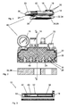
- FIG. 1 is a perspective view of a surface suction 10 is shown, which has a housing 12 which is, for example, a portion of an extruded profile. Alternatively, the housing 12 may also be a bent sheet metal part, 3D printing part, CFRP part or cast iron.
- the housing 12 is closed by two end caps 14 frontally. At the in the FIG. 1 illustrated end cap 14 are a pressure gauge 16, a compressed air connection 18 and other connections 20 are recognizable, which are not essential to the invention.
- a male member 22 which reduces the free space of the housing 12 and as close as possible to the inner surface of the housing 12 hugs, but still has so much game for this, that it is inserted into the housing 12 and removed again, ie can be pulled out.
- the insertion element 22 has on its underside formed as grooves 24 vacuum channels.
- the housing 12 has at its bottom 26 a plurality of rows with suction openings 28, which are designed as flow resistance or for receiving flow valve bodies 30, eg valve balls or the like, are used.
- a flexible pad 32 which is formed by a foam mat 34 or sealing plate attached. This covering 32 is open-pore or in this covering 32, a plurality of slots or openings are introduced, which in turn correspond to the suction openings 28 locally.
- FIG. 2 can be seen that on the inside of the bottom 26 webs 44 extend, in which the suction openings 28 are provided and through which the individual grooves 24 are sealed from each other.
- the grooves 24 are recesses 36, in which, for example, lighting fixtures, reflectors, blow-off nozzles and / or the like can be used. These recesses 36 are in extension behind the suction channels or suction openings 28th
- the insertion element 22 in the housing 12 can be seen and it is a vacuum generator 38 is shown.
- This vacuum generator 38 is in direct connection with the end cap 14, so that over this the Inlets and outlets for fluids and for electrical energy and data can be performed.
- the insertion element 22 is designed as a hollow body 40 and serves as a memory for compressed air or vacuum reservoir. In this case, the vacuum generator is inserted directly into the insertion element 22.
- the trained as a vacuum accumulator hollow body 40 has a closable with a flap opening in the direction of the flow openings 28. The flap can be opened with a cylinder 42 so that abruptly a vacuum is present at the flow openings 28. This has the particular advantage that even slow-acting valve body can be used.
- a memory can be integrated as a separate component in the insertion element 22.
Landscapes
- Engineering & Computer Science (AREA)
- Mechanical Engineering (AREA)
- Robotics (AREA)
- Chemical & Material Sciences (AREA)
- Dispersion Chemistry (AREA)
- Manipulator (AREA)
Description
- Die Erfindung betrifft einen Flächensauggreifer zum Ansaugen und Handhaben von Werkstücken, mit einem Gehäuse, in welchem eine mit Unterdruck beaufschlagbare Unterdruckkammer vorgesehen ist und das Gehäuse an seiner dem Werkstück zugewandten Saugseite Saugöffnungen aufweist.
- Derartige Flächensauggreifer (
DE 10 2006 050 970 A1 ) dienen insbesondere zum lageweisen Ergreifen und Anheben von Gegenständen, wie beispielsweise lagestabile Flachmaterialien, wie z.B. Bretter oder Platten, oder von kleineren Gegenständen, wie z.B. Dosen, Bechern, Schalen oder dergleichen. Der Flächensauggreifer weist einen flexiblen Belag auf, der üblicherweise an die Oberseite der zu greifenden Gegenstände angelegt wird. Als vorteilhaft hat sich ein Schaumstoffbelag erwiesen, da sich dieser an die mitunter unebene Oberfläche gut anschmiegt. Dabei besteht aber weiterhin das Problem, dass unterschiedliche Gegenstände unterschiedliche Oberflächen aufweisen und mitunter zwischen den Gegenständen große Lücken bestehen. - Das Strömungsverhalten ist bei herkömmlichen Flächensauggreifern aber zu träge, als dass dieser schnell auf unterschiedliche Gegenstände reagieren kann.
- Ist der Flächensauggreifer mit Strömungsventilen ausgestattet, dann dürfen die Ventilkörper bei einer vorgegebenen, definierten Saugleistung nicht zu träge sein, da sie ansonsten nicht schließen. Zu schnell reagierende Ventilkörper bergen aber die Gefahr, dass sie auch dann schließen, wenn ein angesaugtes Werkstück z.B. durch Erschütterung kurz abhebt, so dass kurzzeitig Umgebungsluft angesaugt wird. In diesem Fall würde das Werkstück abfallen.
- In den Druckschriften
DE 36 36 523 C2 ,DE 198 17 217 C1 ,US 3 910 621 A undEP 0 267 874 A1 sind Flächensauggreifer beschrieben, bei welchen in der Unterdruckkammer Bauteile angeordnet sind. DieUS 7 661 736 B2 zeigt einen Flächensauggreifer mit den Merkmalen des Oberbegriffs des Anspruchs 1. - Der vorliegenden Erfindung liegt daher die Aufgabe zugrunde, einen Flächensauggreifer der eingangs genannten Art dahingehend weiterzubilden, dass auch träge schließende Ventilkörper einsetzbar sind.
- Dieser Aufgabe wird mit einem Flächensauggreifer nach Anspruch 1 gelöst.
Weitere Merkmale ergeben sich aus den Unteransprüchen. - Durch das Einschubelement wird erfindungsgemäß die Unterdruckkammer innerhalb des Gehäuses verkleinert und dadurch das Ansprechverhalten des Flächensauggreifers verbessert. Da der Totraum durch das Einschubelement verkleinert wird reagiert jede einzelne Saugöffnung auch bei kleinerem Saugvolumenstrom besser. Es muss nicht ein großer Saugraum evakuiert werden. Eventuell vorhandene Strömungsventile können dadurch in ihrem Schließverhalten träg reagierend ausgeführt werden. Diese Gestaltung der Strömungsventile lässt somit ein sicheres Anheben und Transportieren der Gegenstände zu, ohne dass durch Leckage am angesaugten Gegenstand die Gefahr besteht, dass das Strömungsventil während des Hebevorganges schließt. Die Erfindung sichert somit das Transportieren von Gegenständen mit Leckage bei minimalem Einsatz des Gesamtvolumenstroms.
- Ein weiterer Vorteil besteht darin, dass der Flächensauggreifer durch unterschiedliche Einschubelemente an unterschiedliche Einsatzzwecke schnell anpassbar ist, indem lediglich das geeignete Einschubelement in das Gehäuse eingeschoben wird. Dadurch können Funktionen ergänzt oder geändert werden. Der Flächensauggreifer ist nach Art eines Baukastens aufgebaut.
- Bei der Erfindung weist das Einschubelement an seiner der Saugseite des Gehäuses zugewandten Unterseite als Nuten ausgebildete Unterdruckkanäle auf. Diese Unterdruckkanäle sind an den Unterdruckerzeuger angeschlossen und bilden mit den Zuleitungen quasi den einzigen, mit den Saugöffnungen verbundenen Totraum. Dessen Volumen hängt lediglich von den Abmessungen der Nuten und der Zuleitungen ab und kann daher sehr klein gehalten werden.
- Um zu verhindern, dass Leckagen oder unbelegte Saugöffnungen einen Zusammenbruch des gesamten Unterdrucksystems bewirken, können die Nuten gegeneinander abgedichtet sein. Außerdem können die Nuten selbst über ihre Länge ein oder mehrere Trennstege aufweisen.
- Das Gehäuse ist stirnseitig verschließbar und das Einschubelement stirnseitig in das Gehäuse einschiebbar und wieder herausziehbar. Erfindungsgemäß ist das Gehäuse ein Strangpressprofil wobei sich die Nuten in Längsrichtung des Gehäuses bzw. des Profils erstrecken. Die Nuten können also gleich bei der Herstellung des Gehäuses in dieses eingebracht werden, wobei sie an der Innenseite des Saugseite des Gehäuses vorstehen. Wird das Einschubelement in das Gehäuse stirnseitig eingeschoben, dann greifen die Stege in die Nuten des Einschubelements ein.
- Bei einer bevorzugten Weiterbildung der Erfindung ist vorgesehen, dass das Einschubelement wenigstens eine Aufnahmekammer z.B. für einen Ejektor oder Mehrstufenejektor, für einen Druckspeicher oder für einen Unterdruckspeicher aufweist. Der Druck- oder Unterdruckspeicher kann direkt im Einschub gebildet werden. Auf diese Weise liegt an den Saugöffnungen sofort ein Unterdruck an und bei Bedarf kann über den im Druckspeicher gespeicherten Überdruck schnell abgeblasen werden. Durch den höheren Druck können somit auch Verschmutzungen effektiv ausgeblasen werden. Eine Weiterbildung sieht vor, dass elektrische Bauteile, wie Ventile, Sensoren, Energiespeicher, Kameras, Steuerungen usw., innerhalb oder am Einschubelement gelagert sind.
- Eine vorteilhafte Ausführungsform sieht vor, dass das Einschubelement wenigstens eine Beleuchtungseinrichtung aufweist. Die Beleuchtungseinrichtung beleuchtet den Unterdruckkanal und oder eine oder mehrere Saugöffnungen und scheint von innen nach außen. Mit dem Flächensauggreifen kann also vor dem Aufsetzen auf den zu greifenden Gegenstand die Oberfläche des Gegenstands beleuchtet werden ,was insbesondere in schlecht beleuchteten Arbeitsstätten von großem Vorteil ist. Zusätzlich oder alternativ können im Einschubelement und insbesondere hinter den Saugöffnungen Reflektoren vorgesehen sein. Wird von außen in die Saugöffnungen reingeleuchtet, können Verschmutzungen sehr leicht erkannt werden.
- Mit Vorzug sieht die Erfindung weiterhin vor, dass das Einschubelement wenigstens einen Druckluftkanal und/oder Druckluftdüsen aufweist. Über diese Druckluftdüsen können einerseits Verschmutzungen leicht ausgeblasen werden, andererseits dienen diese zum Abblasen des gegriffenen Werkstücks.
- Bei einem anderen Ausführungsbeispiel weist das Einschubelement wenigstens eine elektrisch betriebene Pumpe zur Vakuumerzeugung auf. Die Zuleitung für Druckluft und/oder für Unterdruck bei dieser Variante entfallen. Es werden lediglich elektrische Zuleitungen benötigt.
- Um diesen Flächensauggreifer zumindest kurzfristig auch ohne eine Ankopplung an das Stromnetz betreiben zu können, weist das Einschubelement wenigstens einen Energiespeicher, z.B. einen Akkumulator auf. Dieser betreibt die elektrische Pumpe und kann später wieder aufgeladen werden.
- Weitere Vorteile, Merkmale und Einzelheiten der Erfindung ergeben sich aus den Unteransprüchen sowie der nachfolgenden Beschreibung, in der unter Bezugnahme auf die Zeichnung eine besonders bevorzugte Ausführungsform beschrieben ist. Die in der Zeichnung dargestellten sowie in der Beschreibung und in den Ansprüchen erwähnten Merkmale können jeweils einzeln für sich oder in beliebiger Kombination erfindungswesentlich sein.
- In der Zeichnung zeigen:
-
Figur 1 eine Explosionsdarstellung des erfindungsgemäßen Flächensauggreifers, teilweise aufgeschnitten; -
Figur 2 einen Querschnitt durch den Flächensauggreifer; und -
Figur 3 einen Längsschnitt II - II gemäßFigur 1 durch den Flächensauggreifer. - In der
Figur 1 ist in perspektivischer Darstellung ein Flächensauggreifer 10 dargestellt, der ein Gehäuse 12 aufweist, welches z.B. ein Abschnitt eines Strangpressprofils ist. Alternativ kann das Gehäuse 12 auch ein Blechbiegeteil, 3D-Druckteil, CFK-Teil oder Gusstel sein. Das Gehäuse 12 ist von zwei Endkappen 14 stirnseitig verschlossen. An der in derFigur 1 dargestellten Endkappe 14 sind ein Manometer 16, ein Druckluftanschluss 18 und sind weitere Anschlüsse 20 erkennbar, die für die Erfindung nicht wesentlich sind. Im Gehäuse 12 befindet sich ein Einschubelement 22, welches den freien Innenraum des Gehäuses 12 verkleinert und sich möglichst dicht an die Innenoberfläche des Gehäuses 12 anschmiegt, jedoch noch so viel Spiel zu dieser besitzt, dass es in das Gehäuse 12 eingeschoben und wieder entfernt, d.h. herausgezogen werden kann. Das Einschubelement 22 weist an seiner Unterseite als Nuten 24 ausgebildete Unterdruckkanäle auf. Korrespondierend zu diesen Nuten 24 besitzt das Gehäuse 12 an seinem Boden 26 mehrere Reihen mit Saugöffnungen 28, die als Strömungswiderstand ausgebildet sind oder zur Aufnahme von Strömungsventilkörpern 30, z.B. Ventilkugeln oder dergleichen, dienen. Am den Boden 26 ist ein flexibler Belag 32, welcher von einer Schaumstoffmatte 34 oder Dichtplatte gebildet wird, befestigt. Diesem Belag 32 ist offenporig ausgebildet oder in diesem Belag 32 sind eine Vielzahl von Schlitzen oder Durchbrüchen eingebracht, die wiederum mit den Saugöffnungen 28 örtlich korrespondieren. - Ferner ist in
Figur 2 erkennbar, dass sich an der Innenseite des Bodens 26 Stege 44 erstrecken, in welchen die Saugöffnungen 28 vorgesehen sind und über welche die einzelnen Nuten 24 gegeneinander abgedichtet sind. Oberhalb der Nuten 24 befinden sich Aussparungen 36, in welche z.B. Beleuchtungskörper, Reflektoren, Abblasdüsen und/oder dergleichen eingesetzt werden können. Diese Aussparungen 36 liegen in Verlängerung hinter den Saugkanälen oder Saugöffnungen 28. - Im in der
Figur 3 dargestellten Längsschnitt III - III ist das Einschubelement 22 im Gehäuse 12 erkennbar und es ist ein Vakuumerzeuger 38 dargestellt. Dieser Vakuumerzeuger 38 befindet sich in unmittelbarem Anschluss an die Endkappe 14, so dass über diese die Zu- und Ableitungen für Fluide und für elektrische Energie sowie Daten geführt werden können. Das Einschubelement 22 ist als Hohlkörper 40 ausgebildet und dient als Speicher für Druckluft oder als Unterdruckspeicher. In diesem Fall ist der Unterdruckerzeuger direkt in das Einschubelement 22 eingeschoben. Der als Unterdruckspeicher ausgebildete Hohlkörper 40 besitzt eine mit einer Klappe verschließbare Öffnung in Richtung der Strömungsöffnungen 28. Die Klappe kann mit einem Zylinder 42 geöffnet werden, so dass an den Strömungsöffnungen 28 schlagartig ein Unterdruck ansteht. Dies hat insbesondere den Vorteil, dass auch träge reagierende Ventilkörper verwendet werden können. Außerdem kann in das Einschubelement 22 auch ein Speicher als separates Bauteil integriert sein.
Claims (7)
- Flächensauggreifer (10) zum Ansaugen und Handhaben von Werkstücken, mit einem stirnseitig verschließbaren Gehäuse (12), in welchem eine mit Unterdruck beaufschlagbare Unterdruckkammer vorgesehen ist und das Gehäuse (12) an seiner dem Werkstück zugewandten Saugseite Saugöffnungen (28) aufweist, wobei sich im Gehäuse (12) ein in das Gehäuse (12) stirnseitig einschiebbares und wieder herausziehbares Einschubelement (22) befindet, welches den freien Innenraum des Gehäuses (12) verkleinert und von einem Unterdruckerzeuger gespeiste Unterdruckkanäle (24) aufweist, dadurch gekennzeichnet, dass das Einschubelement (22) an seiner der Saugseite des Gehäuses (12) zugewandten Unterseite als Nuten (24) ausgebildete Unterdruckkanäle aufweist, wobei die Nuten (24) gegeneinander abgedichtet sind,
und dass das Gehäuse (12) ein Strangpressprofil ist und dass sich die Nuten (24) in Längsrichtung des Gehäuses (12) bzw. des Profils erstrecken,
und dass an der Innenseite der Saugseite des Gehäuses (12) Stege (44) vorgesehen sind, die in die Nuten (24) des Einschubelements (22) eingreifen. - Flächensauggreifer nach einem der vorhergehenden Ansprüche, dadurch gekennzeichnet, dass das Einschubelement (22) wenigstens eine Aufnahmekammer (38) z.B. für einen Ejektor oder Mehrstufenejektor, für einen Druckspeicher oder für einen Unterdruckspeicher aufweist.
- Flächensauggreifer nach einem der vorhergehenden Ansprüche, dadurch gekennzeichnet, dass das Einschubelement (22) wenigstens eine Beleuchtungseinrichtung aufweist.
- Flächensauggreifer nach Anspruch 3, dadurch gekennzeichnet, dass die Beleuchtungseinrichtung den Unterdruckkanal (24) und oder eine oder mehrere Saugöffnungen (28) beleuchtet.
- Flächensauggreifer nach einem der vorhergehenden Ansprüche, dadurch gekennzeichnet, dass das Einschubelement (22) wenigstens einen Druckluftkanal und/oder Druckluftdüsen aufweist.
- Flächensauggreifer nach einem der vorhergehenden Ansprüche, dadurch gekennzeichnet, dass das Einschubelement (22) wenigstens eine elektrisch betriebene Pumpe zur Vakuumerzeugung aufweist.
- Flächensauggreifer nach einem der vorhergehenden Ansprüche, dadurch gekennzeichnet, dass das Einschubelement (22) wenigstens einen Energiespeicher, z.B. einen Akkumulator, eine integrierte Elektronik zur Auswertung oder Steuerung von Prozessparametern, eine Einrichtung zur Gewichtserkennung, eine Kamera zur Prozess- und Qualitätskontrolle oder zur Prozesssteuerung, eine Schnittstelle zu einem Roboter und/oder Elemente zur Vakuummessung, -steuerung und -regelung aufweist.
Applications Claiming Priority (2)
| Application Number | Priority Date | Filing Date | Title |
|---|---|---|---|
| DE102013201248.9A DE102013201248B4 (de) | 2013-01-25 | 2013-01-25 | Flächensauggreifer |
| PCT/EP2014/051089 WO2014114621A1 (de) | 2013-01-25 | 2014-01-21 | Flächensauggreifer |
Publications (2)
| Publication Number | Publication Date |
|---|---|
| EP2948277A1 EP2948277A1 (de) | 2015-12-02 |
| EP2948277B1 true EP2948277B1 (de) | 2016-11-16 |
Family
ID=50002714
Family Applications (1)
| Application Number | Title | Priority Date | Filing Date |
|---|---|---|---|
| EP14701341.1A Active EP2948277B1 (de) | 2013-01-25 | 2014-01-21 | Flächensauggreifer |
Country Status (5)
| Country | Link |
|---|---|
| US (1) | US9457478B2 (de) |
| EP (1) | EP2948277B1 (de) |
| CN (1) | CN205009243U (de) |
| DE (1) | DE102013201248B4 (de) |
| WO (1) | WO2014114621A1 (de) |
Families Citing this family (18)
| Publication number | Priority date | Publication date | Assignee | Title |
|---|---|---|---|---|
| JP6215333B2 (ja) * | 2012-10-19 | 2017-10-18 | ダウ グローバル テクノロジーズ エルエルシー | 形成可能および/または折り畳み可能な部品の持ち上げおよび移動のための装置、システム、および方法 |
| EP2952303B1 (de) * | 2014-06-05 | 2017-10-11 | J. Schmalz GmbH | Verfahren zur handhabung von flexiblen mattenartigen werkstücken |
| KR101641164B1 (ko) * | 2014-11-25 | 2016-07-20 | 유도스타자동화 주식회사 | 중량측정장치를 갖춘 다관절 로봇 |
| DE102016113241A1 (de) | 2016-07-19 | 2018-01-25 | J. Schmalz Gmbh | Flächensauggreifer |
| CN108382853A (zh) * | 2018-05-28 | 2018-08-10 | 深圳市鼎达信装备有限公司 | 真空吸附装置及其壳体 |
| AT521384B1 (de) * | 2018-09-20 | 2020-01-15 | Trumpf Maschinen Austria Gmbh & Co Kg | Automatisierter Vakuumgreifer und Verfahren zum sicheren Greifen von Bauteilen |
| DE102018126684A1 (de) | 2018-10-25 | 2020-04-30 | J. Schmalz Gmbh | Sauggreifer |
| CN110053957A (zh) * | 2019-04-29 | 2019-07-26 | 东莞市鸿仁自动化设备科技有限公司 | 一种薄板的智能化堆叠系统及堆叠方法 |
| JP2020189341A (ja) * | 2019-05-17 | 2020-11-26 | 株式会社イシダ | 吸着搬送装置 |
| CN110394820B (zh) * | 2019-06-03 | 2024-11-12 | 亚米拉自动化技术(苏州)有限公司 | 一种紧凑式海绵吸盘 |
| CN110774274A (zh) * | 2019-11-08 | 2020-02-11 | 苏州罗克韦格自动化有限公司 | 一种吸盘式助力机械手 |
| TW202213614A (zh) * | 2020-09-16 | 2022-04-01 | 力成科技股份有限公司 | 晶圓運送裝置 |
| KR102897586B1 (ko) * | 2020-11-30 | 2025-12-10 | 삼성전자주식회사 | 기판 이송 장치 |
| CN112660483B (zh) * | 2020-12-15 | 2022-03-29 | 常州新祺晟高分子科技有限公司 | 一种汽车隔音棉生产用压紧装袋设备 |
| AU2022262313A1 (en) | 2021-04-20 | 2023-11-30 | Nhon Hoa Nguyen | Portable vacuum gripper |
| CN113211351B (zh) * | 2021-05-14 | 2022-03-08 | 中国工程物理研究院激光聚变研究中心 | 一种针对深矢高非球面元件自适应柔性低应力装夹装置及装夹方法 |
| CN116331833B (zh) * | 2023-03-17 | 2023-08-22 | 常州涵洋高分子材料科技有限公司 | 一种汽车用阻燃海绵的转移工装及运送装置 |
| CN118952276A (zh) * | 2024-10-16 | 2024-11-15 | 德州智南针机械科技有限公司 | 一种新能源汽车换电用电池箱抓取装置 |
Family Cites Families (13)
| Publication number | Priority date | Publication date | Assignee | Title |
|---|---|---|---|---|
| US3910621A (en) * | 1973-01-23 | 1975-10-07 | Go Con Concrete Ltd | Suction devices |
| US4265476A (en) * | 1979-08-13 | 1981-05-05 | Alan Elgart | Work-holding device |
| DE3636523A1 (de) | 1986-10-27 | 1988-05-05 | Lewecke Gmbh Maschbau | Vakuum-hebegeraet |
| EP0267874B1 (de) * | 1986-11-10 | 1990-06-27 | Haas-Laser Systems AG | Verfahren zum Transportieren von perforierten plattenförmigen Objekten |
| US5259859A (en) * | 1992-09-02 | 1993-11-09 | Ppg Industries, Inc. | Lightweight vacuum shuttle |
| US5749614A (en) * | 1995-12-04 | 1998-05-12 | Motorola, Inc. | Vacuum pickup tool for placing balls in a customized pattern |
| DE19817217C1 (de) * | 1998-04-17 | 1999-08-05 | Schmalz J Gmbh | Sauggreifer und Einlegeteil für einen Sauggreifer |
| DE10216221C1 (de) * | 2002-04-08 | 2003-10-16 | Schmalz J Gmbh | Flächengreifer |
| DE102005014115A1 (de) | 2005-03-21 | 2006-09-28 | J. Schmalz Gmbh | Vakuum-Hebegerät |
| DE102006013970B4 (de) | 2006-03-15 | 2008-08-14 | J. Schmalz Gmbh | Unterdruckflächengreifvorrichtung |
| DE102006050970B4 (de) | 2006-10-23 | 2010-06-02 | J. Schmalz Gmbh | Flächensauggreifer |
| US8251422B2 (en) * | 2010-03-29 | 2012-08-28 | Asm Assembly Automation Ltd | Apparatus for transferring electronic components in stages |
| CN205169815U (zh) * | 2013-01-25 | 2016-04-20 | J.施迈茨有限公司 | 面吸气夹持器 |
-
2013
- 2013-01-25 DE DE102013201248.9A patent/DE102013201248B4/de active Active
-
2014
- 2014-01-21 EP EP14701341.1A patent/EP2948277B1/de active Active
- 2014-01-21 CN CN201490000392.5U patent/CN205009243U/zh not_active Expired - Lifetime
- 2014-01-21 WO PCT/EP2014/051089 patent/WO2014114621A1/de not_active Ceased
- 2014-01-21 US US14/763,392 patent/US9457478B2/en active Active
Also Published As
| Publication number | Publication date |
|---|---|
| US20150352726A1 (en) | 2015-12-10 |
| EP2948277A1 (de) | 2015-12-02 |
| US9457478B2 (en) | 2016-10-04 |
| CN205009243U (zh) | 2016-02-03 |
| WO2014114621A1 (de) | 2014-07-31 |
| DE102013201248B4 (de) | 2018-03-22 |
| DE102013201248A1 (de) | 2014-07-31 |
Similar Documents
| Publication | Publication Date | Title |
|---|---|---|
| EP2948277B1 (de) | Flächensauggreifer | |
| EP2948278B1 (de) | Flächensauggreifer | |
| DE102020203395B4 (de) | Luftpumpe | |
| DE202017106859U1 (de) | Vakuumgreifer sowie Greifvorrichtung mit Vakuumgreifer | |
| DE112016005979B4 (de) | Kompressor | |
| DE102018204944B4 (de) | Pneumatikgreifer zum Halten eines Blechteils und Fangverfahren in einer Druckausfallsituation an einem solchen Pneumatikgreifer | |
| DE102007034490B4 (de) | Vorrichtung zum Spannen und/oder Halten von Werkstücken | |
| DE20011839U1 (de) | Vakuumerzeugervorrichtung | |
| DE102018122300A1 (de) | Pumpenaggregat zur Bereitstellung eines Hydraulikdrucks zur Betätigung eines Aktors im Antriebsstrang eines Kraftfahrzeugs | |
| DE102006013970B4 (de) | Unterdruckflächengreifvorrichtung | |
| DE102013015055B4 (de) | Saug-Hebevorrichtung zur Manipulation von Gegenständen in z. B. Werkstätten mit zwei wechselweise expaniderenden Bälgen | |
| DE102007020864A1 (de) | Flächengreifereinheit | |
| DE1506502C3 (de) | Greifvorrichtung für tafelartige, ebene Werkstücke, insbesondere Glasscheiben | |
| DE102017008858A1 (de) | Automatisches Schraubgerät für sehr kleine Schrauben | |
| DE102013201603C5 (de) | Vorrichtung und Verfahren zum Zuführen von Kleinteilen an Einbauorten | |
| EP1623799B1 (de) | Saugbalken für eine Vorrrichtung zum Anheben und Umsetzen von Lasten | |
| DE102016202270B4 (de) | Vorrichtung mit einem Luftverdichter und Rückschlagventil | |
| WO2001021357A1 (de) | Vakuum-handhabungs-wechselvorrichtung | |
| DE102016122464B4 (de) | Flüssigkeitspumpe für ein Fördern von Flüssigkeit | |
| DE102024110039B3 (de) | Sauggreifer mit einer flexibel verformbaren Saugkörperwandung und mit einer Verformungseinrichtung zum Verformen der Saugkörperwandung | |
| DE202015100573U1 (de) | Vorrichtung zum Spannen beliebig geformter Werkstücke | |
| DE102018003211B4 (de) | Kolben-Zylinder-Einrichtung mit automatischer Abschaltung, Vakuum-Halter und Vakuum-Auflagetisch | |
| DE102013006224A1 (de) | Anordnung zum Entleeren oder Befüllen eines Transportbehälters | |
| DE29916647U1 (de) | Vakuum-Handhabungs-Wechselvorrichtung | |
| DE102005014115A1 (de) | Vakuum-Hebegerät |
Legal Events
| Date | Code | Title | Description |
|---|---|---|---|
| PUAI | Public reference made under article 153(3) epc to a published international application that has entered the european phase |
Free format text: ORIGINAL CODE: 0009012 |
|
| 17P | Request for examination filed |
Effective date: 20150703 |
|
| AK | Designated contracting states |
Kind code of ref document: A1 Designated state(s): AL AT BE BG CH CY CZ DE DK EE ES FI FR GB GR HR HU IE IS IT LI LT LU LV MC MK MT NL NO PL PT RO RS SE SI SK SM TR |
|
| AX | Request for extension of the european patent |
Extension state: BA ME |
|
| DAX | Request for extension of the european patent (deleted) | ||
| GRAP | Despatch of communication of intention to grant a patent |
Free format text: ORIGINAL CODE: EPIDOSNIGR1 |
|
| INTG | Intention to grant announced |
Effective date: 20160704 |
|
| GRAS | Grant fee paid |
Free format text: ORIGINAL CODE: EPIDOSNIGR3 |
|
| GRAA | (expected) grant |
Free format text: ORIGINAL CODE: 0009210 |
|
| AK | Designated contracting states |
Kind code of ref document: B1 Designated state(s): AL AT BE BG CH CY CZ DE DK EE ES FI FR GB GR HR HU IE IS IT LI LT LU LV MC MK MT NL NO PL PT RO RS SE SI SK SM TR |
|
| REG | Reference to a national code |
Ref country code: GB Ref legal event code: FG4D Free format text: NOT ENGLISH |
|
| REG | Reference to a national code |
Ref country code: CH Ref legal event code: EP |
|
| REG | Reference to a national code |
Ref country code: IE Ref legal event code: FG4D Free format text: LANGUAGE OF EP DOCUMENT: GERMAN |
|
| REG | Reference to a national code |
Ref country code: AT Ref legal event code: REF Ref document number: 845466 Country of ref document: AT Kind code of ref document: T Effective date: 20161215 |
|
| REG | Reference to a national code |
Ref country code: DE Ref legal event code: R096 Ref document number: 502014001984 Country of ref document: DE |
|
| REG | Reference to a national code |
Ref country code: FR Ref legal event code: PLFP Year of fee payment: 4 |
|
| REG | Reference to a national code |
Ref country code: SE Ref legal event code: TRGR |
|
| PG25 | Lapsed in a contracting state [announced via postgrant information from national office to epo] |
Ref country code: LV Free format text: LAPSE BECAUSE OF FAILURE TO SUBMIT A TRANSLATION OF THE DESCRIPTION OR TO PAY THE FEE WITHIN THE PRESCRIBED TIME-LIMIT Effective date: 20161116 |
|
| REG | Reference to a national code |
Ref country code: NL Ref legal event code: MP Effective date: 20161116 |
|
| REG | Reference to a national code |
Ref country code: LT Ref legal event code: MG4D |
|
| PG25 | Lapsed in a contracting state [announced via postgrant information from national office to epo] |
Ref country code: GR Free format text: LAPSE BECAUSE OF FAILURE TO SUBMIT A TRANSLATION OF THE DESCRIPTION OR TO PAY THE FEE WITHIN THE PRESCRIBED TIME-LIMIT Effective date: 20170217 Ref country code: LT Free format text: LAPSE BECAUSE OF FAILURE TO SUBMIT A TRANSLATION OF THE DESCRIPTION OR TO PAY THE FEE WITHIN THE PRESCRIBED TIME-LIMIT Effective date: 20161116 Ref country code: NL Free format text: LAPSE BECAUSE OF FAILURE TO SUBMIT A TRANSLATION OF THE DESCRIPTION OR TO PAY THE FEE WITHIN THE PRESCRIBED TIME-LIMIT Effective date: 20161116 Ref country code: NO Free format text: LAPSE BECAUSE OF FAILURE TO SUBMIT A TRANSLATION OF THE DESCRIPTION OR TO PAY THE FEE WITHIN THE PRESCRIBED TIME-LIMIT Effective date: 20170216 |
|
| PG25 | Lapsed in a contracting state [announced via postgrant information from national office to epo] |
Ref country code: HR Free format text: LAPSE BECAUSE OF FAILURE TO SUBMIT A TRANSLATION OF THE DESCRIPTION OR TO PAY THE FEE WITHIN THE PRESCRIBED TIME-LIMIT Effective date: 20161116 Ref country code: FI Free format text: LAPSE BECAUSE OF FAILURE TO SUBMIT A TRANSLATION OF THE DESCRIPTION OR TO PAY THE FEE WITHIN THE PRESCRIBED TIME-LIMIT Effective date: 20161116 Ref country code: PT Free format text: LAPSE BECAUSE OF FAILURE TO SUBMIT A TRANSLATION OF THE DESCRIPTION OR TO PAY THE FEE WITHIN THE PRESCRIBED TIME-LIMIT Effective date: 20170316 Ref country code: PL Free format text: LAPSE BECAUSE OF FAILURE TO SUBMIT A TRANSLATION OF THE DESCRIPTION OR TO PAY THE FEE WITHIN THE PRESCRIBED TIME-LIMIT Effective date: 20161116 Ref country code: BE Free format text: LAPSE BECAUSE OF NON-PAYMENT OF DUE FEES Effective date: 20170131 Ref country code: ES Free format text: LAPSE BECAUSE OF FAILURE TO SUBMIT A TRANSLATION OF THE DESCRIPTION OR TO PAY THE FEE WITHIN THE PRESCRIBED TIME-LIMIT Effective date: 20161116 Ref country code: RS Free format text: LAPSE BECAUSE OF FAILURE TO SUBMIT A TRANSLATION OF THE DESCRIPTION OR TO PAY THE FEE WITHIN THE PRESCRIBED TIME-LIMIT Effective date: 20161116 |
|
| PG25 | Lapsed in a contracting state [announced via postgrant information from national office to epo] |
Ref country code: EE Free format text: LAPSE BECAUSE OF FAILURE TO SUBMIT A TRANSLATION OF THE DESCRIPTION OR TO PAY THE FEE WITHIN THE PRESCRIBED TIME-LIMIT Effective date: 20161116 Ref country code: CZ Free format text: LAPSE BECAUSE OF FAILURE TO SUBMIT A TRANSLATION OF THE DESCRIPTION OR TO PAY THE FEE WITHIN THE PRESCRIBED TIME-LIMIT Effective date: 20161116 Ref country code: DK Free format text: LAPSE BECAUSE OF FAILURE TO SUBMIT A TRANSLATION OF THE DESCRIPTION OR TO PAY THE FEE WITHIN THE PRESCRIBED TIME-LIMIT Effective date: 20161116 Ref country code: SK Free format text: LAPSE BECAUSE OF FAILURE TO SUBMIT A TRANSLATION OF THE DESCRIPTION OR TO PAY THE FEE WITHIN THE PRESCRIBED TIME-LIMIT Effective date: 20161116 Ref country code: RO Free format text: LAPSE BECAUSE OF FAILURE TO SUBMIT A TRANSLATION OF THE DESCRIPTION OR TO PAY THE FEE WITHIN THE PRESCRIBED TIME-LIMIT Effective date: 20161116 |
|
| REG | Reference to a national code |
Ref country code: DE Ref legal event code: R097 Ref document number: 502014001984 Country of ref document: DE |
|
| PG25 | Lapsed in a contracting state [announced via postgrant information from national office to epo] |
Ref country code: SM Free format text: LAPSE BECAUSE OF FAILURE TO SUBMIT A TRANSLATION OF THE DESCRIPTION OR TO PAY THE FEE WITHIN THE PRESCRIBED TIME-LIMIT Effective date: 20161116 Ref country code: BG Free format text: LAPSE BECAUSE OF FAILURE TO SUBMIT A TRANSLATION OF THE DESCRIPTION OR TO PAY THE FEE WITHIN THE PRESCRIBED TIME-LIMIT Effective date: 20170216 |
|
| REG | Reference to a national code |
Ref country code: CH Ref legal event code: PL |
|
| PLBE | No opposition filed within time limit |
Free format text: ORIGINAL CODE: 0009261 |
|
| STAA | Information on the status of an ep patent application or granted ep patent |
Free format text: STATUS: NO OPPOSITION FILED WITHIN TIME LIMIT |
|
| PG25 | Lapsed in a contracting state [announced via postgrant information from national office to epo] |
Ref country code: MC Free format text: LAPSE BECAUSE OF FAILURE TO SUBMIT A TRANSLATION OF THE DESCRIPTION OR TO PAY THE FEE WITHIN THE PRESCRIBED TIME-LIMIT Effective date: 20161116 |
|
| 26N | No opposition filed |
Effective date: 20170817 |
|
| PG25 | Lapsed in a contracting state [announced via postgrant information from national office to epo] |
Ref country code: CH Free format text: LAPSE BECAUSE OF NON-PAYMENT OF DUE FEES Effective date: 20170131 Ref country code: LI Free format text: LAPSE BECAUSE OF NON-PAYMENT OF DUE FEES Effective date: 20170131 |
|
| REG | Reference to a national code |
Ref country code: IE Ref legal event code: MM4A |
|
| PG25 | Lapsed in a contracting state [announced via postgrant information from national office to epo] |
Ref country code: SI Free format text: LAPSE BECAUSE OF FAILURE TO SUBMIT A TRANSLATION OF THE DESCRIPTION OR TO PAY THE FEE WITHIN THE PRESCRIBED TIME-LIMIT Effective date: 20161116 Ref country code: LU Free format text: LAPSE BECAUSE OF NON-PAYMENT OF DUE FEES Effective date: 20170121 |
|
| REG | Reference to a national code |
Ref country code: FR Ref legal event code: PLFP Year of fee payment: 5 |
|
| REG | Reference to a national code |
Ref country code: BE Ref legal event code: MM Effective date: 20170131 |
|
| PG25 | Lapsed in a contracting state [announced via postgrant information from national office to epo] |
Ref country code: IE Free format text: LAPSE BECAUSE OF NON-PAYMENT OF DUE FEES Effective date: 20170121 |
|
| GBPC | Gb: european patent ceased through non-payment of renewal fee |
Effective date: 20180121 |
|
| PG25 | Lapsed in a contracting state [announced via postgrant information from national office to epo] |
Ref country code: MT Free format text: LAPSE BECAUSE OF FAILURE TO SUBMIT A TRANSLATION OF THE DESCRIPTION OR TO PAY THE FEE WITHIN THE PRESCRIBED TIME-LIMIT Effective date: 20161116 |
|
| PG25 | Lapsed in a contracting state [announced via postgrant information from national office to epo] |
Ref country code: GB Free format text: LAPSE BECAUSE OF NON-PAYMENT OF DUE FEES Effective date: 20180121 |
|
| PG25 | Lapsed in a contracting state [announced via postgrant information from national office to epo] |
Ref country code: HU Free format text: LAPSE BECAUSE OF FAILURE TO SUBMIT A TRANSLATION OF THE DESCRIPTION OR TO PAY THE FEE WITHIN THE PRESCRIBED TIME-LIMIT; INVALID AB INITIO Effective date: 20140121 |
|
| PG25 | Lapsed in a contracting state [announced via postgrant information from national office to epo] |
Ref country code: CY Free format text: LAPSE BECAUSE OF FAILURE TO SUBMIT A TRANSLATION OF THE DESCRIPTION OR TO PAY THE FEE WITHIN THE PRESCRIBED TIME-LIMIT Effective date: 20161116 |
|
| PG25 | Lapsed in a contracting state [announced via postgrant information from national office to epo] |
Ref country code: MK Free format text: LAPSE BECAUSE OF FAILURE TO SUBMIT A TRANSLATION OF THE DESCRIPTION OR TO PAY THE FEE WITHIN THE PRESCRIBED TIME-LIMIT Effective date: 20161116 |
|
| REG | Reference to a national code |
Ref country code: AT Ref legal event code: MM01 Ref document number: 845466 Country of ref document: AT Kind code of ref document: T Effective date: 20190121 |
|
| PG25 | Lapsed in a contracting state [announced via postgrant information from national office to epo] |
Ref country code: TR Free format text: LAPSE BECAUSE OF FAILURE TO SUBMIT A TRANSLATION OF THE DESCRIPTION OR TO PAY THE FEE WITHIN THE PRESCRIBED TIME-LIMIT Effective date: 20161116 |
|
| PG25 | Lapsed in a contracting state [announced via postgrant information from national office to epo] |
Ref country code: AT Free format text: LAPSE BECAUSE OF NON-PAYMENT OF DUE FEES Effective date: 20190121 |
|
| PG25 | Lapsed in a contracting state [announced via postgrant information from national office to epo] |
Ref country code: AL Free format text: LAPSE BECAUSE OF FAILURE TO SUBMIT A TRANSLATION OF THE DESCRIPTION OR TO PAY THE FEE WITHIN THE PRESCRIBED TIME-LIMIT Effective date: 20161116 Ref country code: IS Free format text: LAPSE BECAUSE OF FAILURE TO SUBMIT A TRANSLATION OF THE DESCRIPTION OR TO PAY THE FEE WITHIN THE PRESCRIBED TIME-LIMIT Effective date: 20170316 |
|
| P01 | Opt-out of the competence of the unified patent court (upc) registered |
Effective date: 20230620 |
|
| PGFP | Annual fee paid to national office [announced via postgrant information from national office to epo] |
Ref country code: SE Payment date: 20260121 Year of fee payment: 13 |
|
| PGFP | Annual fee paid to national office [announced via postgrant information from national office to epo] |
Ref country code: DE Payment date: 20260323 Year of fee payment: 13 |
|
| PGFP | Annual fee paid to national office [announced via postgrant information from national office to epo] |
Ref country code: IT Payment date: 20260130 Year of fee payment: 13 |
|
| PGFP | Annual fee paid to national office [announced via postgrant information from national office to epo] |
Ref country code: FR Payment date: 20260123 Year of fee payment: 13 |