EP2948378B1 - Scelleuse à vide à détecteur de proximité à semi-conducteur - Google Patents
Scelleuse à vide à détecteur de proximité à semi-conducteur Download PDFInfo
- Publication number
- EP2948378B1 EP2948378B1 EP14743299.1A EP14743299A EP2948378B1 EP 2948378 B1 EP2948378 B1 EP 2948378B1 EP 14743299 A EP14743299 A EP 14743299A EP 2948378 B1 EP2948378 B1 EP 2948378B1
- Authority
- EP
- European Patent Office
- Prior art keywords
- vpa
- operations
- container material
- proximity sensor
- flexible container
- Prior art date
- Legal status (The legal status is an assumption and is not a legal conclusion. Google has not performed a legal analysis and makes no representation as to the accuracy of the status listed.)
- Not-in-force
Links
Images




Classifications
-
- B—PERFORMING OPERATIONS; TRANSPORTING
- B65—CONVEYING; PACKING; STORING; HANDLING THIN OR FILAMENTARY MATERIAL
- B65B—MACHINES, APPARATUS OR DEVICES FOR, OR METHODS OF, PACKAGING ARTICLES OR MATERIALS; UNPACKING
- B65B57/00—Automatic control, checking, warning, or safety devices
- B65B57/02—Automatic control, checking, warning, or safety devices responsive to absence, presence, abnormal feed, or misplacement of binding or wrapping material, containers, or packages
-
- B—PERFORMING OPERATIONS; TRANSPORTING
- B65—CONVEYING; PACKING; STORING; HANDLING THIN OR FILAMENTARY MATERIAL
- B65B—MACHINES, APPARATUS OR DEVICES FOR, OR METHODS OF, PACKAGING ARTICLES OR MATERIALS; UNPACKING
- B65B31/00—Packaging articles or materials under special atmospheric or gaseous conditions; Adding propellants to aerosol containers
- B65B31/02—Filling, closing, or filling and closing, containers or wrappers in chambers maintained under vacuum or superatmospheric pressure or containing a special atmosphere, e.g. of inert gas
- B65B31/024—Filling, closing, or filling and closing, containers or wrappers in chambers maintained under vacuum or superatmospheric pressure or containing a special atmosphere, e.g. of inert gas specially adapted for wrappers or bags
-
- B—PERFORMING OPERATIONS; TRANSPORTING
- B65—CONVEYING; PACKING; STORING; HANDLING THIN OR FILAMENTARY MATERIAL
- B65B—MACHINES, APPARATUS OR DEVICES FOR, OR METHODS OF, PACKAGING ARTICLES OR MATERIALS; UNPACKING
- B65B31/00—Packaging articles or materials under special atmospheric or gaseous conditions; Adding propellants to aerosol containers
- B65B31/04—Evacuating, pressurising or gasifying filled containers or wrappers by means of nozzles through which air or other gas, e.g. an inert gas, is withdrawn or supplied
- B65B31/046—Evacuating, pressurising or gasifying filled containers or wrappers by means of nozzles through which air or other gas, e.g. an inert gas, is withdrawn or supplied the nozzles co-operating, or being combined, with a device for opening or closing the container or wrapper
- B65B31/048—Evacuating, pressurising or gasifying filled containers or wrappers by means of nozzles through which air or other gas, e.g. an inert gas, is withdrawn or supplied the nozzles co-operating, or being combined, with a device for opening or closing the container or wrapper specially adapted for wrappers or bags
Definitions
- the Inventive arrangements relate to Vacuum Packaging Appliances ("VPA"). More particularly, the invention concerns ATA employing solid state proximity detectors for detecting when a container is inserted into the VP A.
- Various appliances are used for vacuum packaging purposes to protect perishables and other products against oxidation.
- Such appliances typically use heat sealing elements to form seals at open ends of containers.
- the heat sealing elements can include one heat sealing bar or two adjacent heat sealing bars over which an open end of a container is placed.
- a container Prior to formation of a heat seal, a container may be evacuated of excess moisture and air through the use of at least one vacuum pump. The evacuation of moisture and air from the container minimizes the spoiling effects of oxygen on perishables and other products.
- Such appliances may also comprise a means for detecting when the container is properly Inserted therein.
- the means typically comprise mechanical flags configured to initiate the recognition that a container has been inserted into the respective appliance.
- at least one mechanical structure e.g., pendulums and springs
- a container material is inserted properly within the appliance (e.g., across a majority of an entire length of a vacuum chamber trough).
- movement of a mechanical flag is accomplished by inserting more bag material into the appliance.
- US 2010/0095638 A1 discloses a vacuum sealing appliance and a method for vacuum sealing with such an appliance according to the features of the preamble of the independent claims.
- US 2011/126986 discloses a bag sealer that can inflate as well as evacuate, for normal household use, to keep foodstuff fresh.
- the present Invention concerns a method according to claim 1 and an apparatus according to claim 7 and variants thereof.
- the method comprises detecting when container material is at least partially disposed within a transparent vacuum chamber of the VPA using a proximity sensor mechanism. This detection can be performed in response to a lid of the VPA being locked In a closed position.
- a signal is communicated from the proximity sensor mechanism to an electronic circuit of the VPA in response to the detection of the container material within the vacuum chamber, in response to the reception of the signal by the electronic circuit, the performance of a first operation by the VPA is triggered.
- the first operation can he selected from the group comprising at least one of: mechanical clamping operations to clamp the container material in position; vacuum operations to extract fluid from within container defined by the container material; lock releasing operations to allow actuation of a cutting device; heat sealing operations to create a heat seal along an open end of the container; and lowering operations to transition a cutting device from a retracted position Into a cutting position.
- the VPA has an automatic dispensing feature.
- the method further comprises automatically dispensing container material from a roll of container material disposed in the VPA.
- the proximity sensor mechanism further detects when an amount of container material contained on a roll disposed within the VPA Is at or below a certain level. When such detection is made, at least one of the following operations can be performed by the VPA: suspend automatic dispensing operations; and release a lock locking a lid of the VPA in a closed position.
- the proximity sensor mechanism can comprise: an emitter configured to emit light in proximity to and in a direction towards a vacuum chamber of the VPA; and a detector configured to detect the light reflected from the container material disposed in the VPA.
- the present invention generally concerns systems and methods for causing certain operations to be performed by a VPA.
- the methods comprise detecting when container material is at least partially disposed within a transparent vacuum chamber of the VPA using a proximity sensor mechanism. This detection can be performed in response to a lid of the VPA being locked in a closed position.
- a signal is communicated from the proximity sensor mechanism to an electronic circuit of the VPA in response to the detection of the container material within the vacuum chamber.
- the performance of a first operation by the VPA is triggered.
- the first operation can be selected from the group comprising at least one of: mechanical clamping operations to clamp the container material in position; vacuum operations to extract fluid from within a container defined by the container material; lock releasing operations to allow actuation of a cutting device; heat sealing operations to create a heat seal along an open end of the container; and lowering operations to transition a cutting device from a retracted position into a cutting position.
- the present invention has certain advantages over conventional VPAs.
- VPAs employing the mechanical flag approach described in the background section of this document suffers from certain drawbacks.
- the mechanical flag structure could cause container material to wrinkle, thereby resulting in a false detection or other error.
- Such false detection has been eliminated by the present invention since the proximity sensor is never in contact with the container material.
- the mechanical structures of the conventional mechanical flag approach are relatively mechanically complex and expensive, as compared to the proximity sensor mechanism of the present invention.
- Embodiments will now be described with respect to FIGS. 1-8 .
- Embodiments generally relate to VPAs configured to seal perishables or other products within a container.
- An example container 100 comprising at least one seal formed along an edge thereof is provided in FIG. 1 .
- the container can include, but is not limited to, a plastic bag 102 with one or more seals 104, 106, 108, 110 formed on edges thereof.
- At least one of the seals 110 is formed by a VPA. If less than all of the seals are formed by the VPA, then the remaining seals may have been pre-formed at a factory. In all cases, perishables 112 or other products may be disposed in the container 100 for protection against oxidation.
- VPA 200 is generally configured to evacuate and seal a container (e.g., container 100 of FIG. 1 ). VPA 200 may also be configured to dispense a material that can be used to form the container.
- VPA 200 comprises a base 210 with a storage compartment 302 formed therein.
- the storage compartment 302 is provided for at least partially housing a roll 304 of flexible container material.
- the flexible container material comprises a multi-layer plastic material with at least two edges having pre-formed seals therealong (e.g., seals 106 and 108 of FIG. 1 ).
- the roll 304 may be stored in the storage compartment 302 with or without any support mechanisms. In both cases, the roll 304 is free to at least rotate within compartment 302.
- a pivoting lid 202 is hingedly coupled to the base 210 of the VPA 200.
- the pivoting lid 202 can be transitioned between a closed position shown in FIG. 2 and an open position shown in FIG. 3 .
- a user may manually cause such a transition using a lip 212 formed on an exterior front edge of the lid 202.
- the lip 212 allows the user to easily grasp and pivot the lid 202 about its pivot point for transitioning the lid to and from its closed position or its open position.
- the pivot point is defined by the hinge(s) (not shown) pivotally coupling a rear bottom edge 314 of the lid 202 to the base 210.
- the lid 202 may be locked into the closed position via a latch mechanism 316, 318, 320.
- the latch mechanism comprises a depressible lever 316 and two hooks 318, 320 configured to engage latch cams (not shown) disposed in the base 210.
- the latch cams are accessible to the hooks 318, 320 via apertures 322, 342 formed in the base 210.
- the hooks 318, 320 are sized and shaped to pass through respective apertures 322, 342 when the lid 202 is pivoted in the direction of arrow 324 into the closed position.
- the lever 316 allows a user to cause the hooks 318, 320 to lockingly engage the latch cams so that the lid 202 is locked into its closed position.
- the hooks can be disengaged from the latch cams automatically by the VPA 200 or manually by the user via the lever 316, In the manual scenario, the lever locks the latch mechanism when moved in a downward direction and unlocks the latch mechanism when moved in an upward direction.
- the pivoting lid 202 When the pivoting lid 202 is in its closed position, it encloses the roll 304 within the storage compartment 302, as shown in FIG. 2 . Also, container material can be automatically dispensed from the storage compartment 302 into a vacuum chamber of the VPA 200. Additionally or alternatively, the pivoting lid 202 can allow a section of container material to be manually dispensed from the storage compartment 302 when it is in its open position, as shown in FIG. 3 . Once at least a portion of the container material is dispensed from the storage compartment 302, the pivoting lid 202 can be returned to its locked closed position.
- a proximity sensor mechanism 460, 462 can be provided to perform certain operations subsequent to the placement of the pivoting lid 202 in its locked closed position.
- the proximity sensor mechanism 460, 462 will be described in detail below. Still, it should be understood that the proximity sensor mechanism 460, 462 can detect when the roll 304 is running out of container material (e.g., the amount of container material contained on the roll is at or falls below a certain level). Upon such detection, the proximity sensor mechanism 460, 462 can generate and communicate a signal to electronic circuitry of the VPA 200 so as to trigger certain operations.
- the operations can include, but are not limited to, the following: terminating or suspending automatic dispensing operations; releasing the latch mechanism locking the lid in its closed position; and/or outputting an indicator to a user of the VPA indicating that the roll needs to be replaced. After replacement of the roll, the automatic dispensing operations can be re-started.
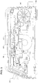
- the proximity sensor mechanism 460, 462 is disposed between the roll 304 and a vacuum trough of the VPA, as shown in FIG. 4 .
- the present invention is not limited in this regard.
- the proximity sensor mechanism 460, 462 alternatively or additionally can be at least partially disposed between a front panel/surface of the VPA and the vacuum trough.
- the proximity sensor mechanism 460, 462 can be used to determine whether the dispensed container material is in a proper position within the VPA (i.e., determine that the container material is not folded or wrinkled). If it is determined that the dispensed container material is properly positioned within the VPA, then a clamping mechanism can be actuated for purposes of clamping the dispensed container material in position.
- the section of clamped container material may then be cut from the roll 304.
- the cutting is achieved using a cutting device 204 integrated within the VPA 200.
- a cutting device 204 integrated within the VPA 200.
- Such cutting device arrangements are well known in the art, and therefore will not be described in detail herein. Still, it should be understood that the cutting device 204 is moveably disposed within a track 206 formed in the pivoting lid 202 of the VPA 200. Any container material disposed below the cutting device 204 can be cut simply by sliding the cutting device 204 back and forth (or right and left) as shown by arrow 208 within the track 206.
- the above detection(s) by the proximity sensor mechanism 460, 462 can trigger certain mechanical and/or electronic operations by the VPA for facilitating the cutting of the dispensed container material.
- a locking mechanism (not shown) may be released thereby allowing the cutting device 204 to be actuated automatically or manually.
- the cutting device 204 can be lowered into position via a lowering mechanism (not shown for ease of explanation) in response to said detection.
- lowering mechanisms are well known in the art, and therefore will not be described herein.
- the lowering mechanism can include, but is not limited to, an inflatable bladder, a pneumatic cylinder, a hydraulic cylinder, resilient members, and/or electro-magnets.
- the cut section of container material is used to form a partially sealed container into which perishables or other products (e.g., items 112 of FIG. 1 ) can be disposed.
- the VPA 200 is used to form a seal (e.g., seal 104 of FIG. 1 ) in an open end of the cut section of container material.
- the seal is formed using a sealing mechanism of the VPA 200.
- the sealing mechanism comprises a bumper 334 and at least one heat sealing strip 336, 338. At least one of the components 334-338 of the sealing mechanism can be retractable for various reasons. Still, at this time it should be understood that the bumper 334 is disposed on the pivoting lid 202 and the heat sealing strip 336, 338 is disposed on the base 210 of the VPA 200. Embodiments of the present invention are not limited in this regard.
- the bumper 334 can alternatively be disposed on/in the base, while the heat sealing strip 336, 338 is disposed on/in the pivoting lid 202.
- the bumper 334 and heat sealing strip 336, 338 are arranged to mate against each other when the lid 202 is in its closed position and a heat seal is to be formed.
- the open end of the container material can be sandwiched between elements 334,336,338 of the sealing mechanism. Thereafter, heat can be applied to the open end of the container material via the heat sealing strip 336, 338 so as to form a heat seal (e.g., seal 110 of FIG. 1 ) thereon.
- the remaining open end of the partially sealed container is placed within the VPA 200.
- the lid 202 is once again transitioned into its locked closed position.
- the proximity sensor mechanism 460, 462 can detect when the remaining open end of the partially sealed container is disposed properly within the VPA so as to at least partially protrude into a lower vacuum trough 306. Upon such detection, mechanical clamping operations and/or vacuum operations of the VPA 200 can be triggered.
- the vacuum operations performed by the VPA 200 involve evacuating excess moisture and air from the interior of the partially sealed container.
- the evacuation of excess moisture and air is achieved using at least one vacuum pump (not shown) and a sealed vacuum chamber.
- the evacuation of moisture and air from the container minimizes the spoiling effects of oxygen on perishables and other products.
- the sealed vacuum chamber is formed by elements of the base 210 and lid 202. More specifically, the base 210 comprises the lower vacuum trough 306 and a gasket 308. Similarly, the pivoting lid 202 comprises an upper vacuum trough 310 and a gasket 312. The troughs 306, 310 and gaskets 308, 312 are arranged to be respectively vertically and horizontally aligned with each other when the lid 202 is in its closed position so as to form a composite sealed vacuum chamber.
- a Vacuum Motor Assembly (“VMA”) 340 is disposed in the base 210 behind the lower vacuum trough 306 for providing evacuating suction within the sealed vacuum chamber.
- VMA Vacuum Motor Assembly
- a predetermined pressure is reached in the vacuum chamber as measured by a pressure sensor 506
- current can be applied to the heat sealing strip(s) 336, 338 for heating the same to a specified temperature (e.g., 160° C to 200° C).
- a specified temperature e.g. 160° C to 200° C.
- the vacuum operations are not completed until some specified time after formation of the seal. This ensures that any additional food or moisture between the two film layers between the newly formed seal and respective open end of the container are removed.
- control panel 326 The forgoing vacuum and sealing operations are controlled by the user through use of a control panel 326.
- the control panel 326 is only operative when the lid 202 is in its locked closed position.
- the control panel 326 is disposed on the base 210 so as to be directly adjacent to the lid 202 when it is in the closed position, as shown in FIG. 2 .
- the control panel 326 comprises electronic control circuitry 504.
- the electronic control circuitry 504 may be at least partially disposed on a circuit board 328.
- the circuit board 328 is located directly beneath the user interface 330 of the control panel 326.
- the electronic control circuitry 504 is electrically connected to the VMA 340, sealing mechanism 334-338, proximity sensor mechanism 460, 462 and/or power circuit of the VPA 200. Operations of some or all of these components 332-340, 460, 462 are controlled by the electronic control circuitry 504.
- the electronic control circuitry 504 can include, but is not limited to, a microprocessor 502, a system bus, a memory, a system interface and/or other hardware/software elements.
- the memory can comprise volatile memory and non-volatile memory. Various types of information can be stored in the memory. Such information includes, but is not limited to, processing results, control programs, parameter values, and/or measurement values.
- the other hardware elements may comprise, but are not limited to, temperature sensors 424, 426.
- the temperature sensors 424, 426 are disposed adjacent to or in proximity to the heat sealing strip(s) 336, 338, respectively. In some scenarios, the temperature sensors 424, 426 are located at various locations along the entire length of the heat sealing strip 336, 338. In other scenarios, the temperature sensors can alternatively or additionally be disposed on the length of the bumper 334.
- the temperature sensors 424, 426 are provided to continuously or periodically measure the temperature of the heat sealing strip(s) 336, 338. Such temperature detection can be used to ensure that the proper sealing temperature is being applied along the entire width of the container during the heat sealing process, as well as optionally control when the heat sealing strips are raised and/or lowered. In this regard, measurement values output from the temperature sensors 424, 426 are communicated to the electronic control circuitry 504 for further processing.
- the microprocessor 502 may be configured to determine a mean average temperature of the heat sealing strip(s) 336, 338 and adjust current output thereto accordingly. Current can be applied to the heat sealing strip(s) 336, 338 for a predetermined period of time such that the temperature thereof is sufficient for forming a seal on an open end of a container.
- the other hardware elements may also comprise a liquid level sensor 510.
- the liquid level sensor 510 is configured to detect an amount of accumulated liquid in a drip tray 350 of the VPA 200.
- the drip tray 350 rests in the lower vacuum trough 306 during operation of the VPA 200 for collecting excess liquids evacuated from the container (e.g., container 100 of FIG. 1 ).
- the drip tray 350 can be removed from the lower vacuum trough 306 so that the evacuated liquid can be discarded.
- the liquid level sensor 510 facilitates a determination by the electronic control circuitry 504 as to when the excess liquid should be removed. In this regard, the output of the liquid level sensor 510 is communicated to the electronic control circuitry 504 for further processing.
- This processing involves analyzing the output of the liquid level sensor 510 to detect when the liquid in the drip tray 350 exceeds a particular threshold level.
- the electronic control circuitry 504 may perform operations to temporarily disable the VMA 340 and heat sealing elements 336, 338, as well as indicate to the user that the excess liquid should be removed from the drip tray 350. Once the excess liquid is removed, the VMA 340 and heat sealing elements 336, 338 are once again enabled.
- the user interface 330 can include, but is not limited to, switches 402-406, Light Emitting Diodes ("LEDs") 408-422, and/or a display screen (not shown).
- One or more of the switches can be a power switch configured to enable the turning on and/or off of the VPA 200.
- a power circuit of the VPA 200 e.g., transformer 332 and/or a battery.
- the power circuit can include an internal power source (e.g., a battery) or a plug 508 for connecting the VPA 200 to an external power source (e.g., a wall mount socket).
- One or more of the switches 402-406 can be configured to enable a user to control the heat sealing operations.
- the same or different switch 402-406 can be configured to control the vacuum operations. For example, in some scenarios, it may be desirable to commence only the heat sealing operations for sealing an open end of the container material after being cut and prior to being filled with perishables or other products. Additionally, it may be desirable to commence: the vacuum operations once the perishables or other products have been inserted into the partially sealed container; and the heat sealing operations subsequent to the evacuation of at least some fluid from the interior of the container during the vacuum operations.
- One or more of the LEDs 408-422 or other indicia of the control panel 326 can be used to indicate to the user when the heat sealing operations and/or the vacuum operations are being performed and/or have been completed. For example, an LED may emit red light when the heat sealing operations are being performed. Once the heat sealing operations are completed, the LED can cease emitting light.
- a proximity sensor mechanism 460, 462 is provided for detecting pre-defined conditions.
- the proximity sensor mechanism 460, 462 is configured to detect when a container material is disposed below the cutting device 204 and/or for detecting when an open end of a partially sealed container is disposed within the VPA 200 so as to at least partially protrude into a lower vacuum trough 306.
- certain mechanical and/or electronic operations of the VPA 200 can be triggered and/or performed.
- one or more of the following operations can be triggered in response to said detection: terminating or suspending automatic dispensing operations of a VPA; releasing a locking mechanism so as to allow the cutting device to be actuated automatically or manually; lowering the cutting device into position via a lowering mechanism; initiating clamping operations by the VPA; initiating vacuum operations by the VPA; and/or initiating heat sealing operations by the VPA.
- Proximity sensor mechanism 700 is generally configured to detect the presence of a nearby object without any physical contact therewith.
- the object can include, but is not limited to, at least a portion of a sealed or partially sealed container.
- the object being sensed is also referred to herein as the proximity sensor mechanism's target.
- Different proximity sensor mechanism targets demand different types of sensors. For example, if the container material is plastic, then the sensors may comprise a photoelectric sensor.
- the proximity sensor mechanism 700 comprises an emitter 702 and a detector 704.
- the emitter 702 is configured to emit an electromagnetic radiation (infrared, for instance) 710.
- the detector 704 is configured to detect any changes in the field or return signal 712.
- Such emitters and detectors are well known in the art, and therefore will not be described herein. However, the specific use of such emitters and detectors as described herein is not known in the art, and therefore is novel.
- the sensor arrangement shown in FIG. 7 is a retro-reflective arrangement. Accordingly, the emitter 702 and the detector 704 are placed at approximately the same horizontal distance D (e.g., distance 480 of FIG. 4 ) from the lower vacuum trough 306. The emitter 702 and detector 704 are also offset from one another by a distance D offset . Embodiments of the present invention are not limited to this particular arrangement of the emitter and detector. Other arrangements can be used which are suitable for a particular application.
- the detector 704 is configured to detect light reflected off of a container 708.
- the container 708 is disposed within a lower vacuum trough (e.g., lower vacuum trough 306 of FIG. 3 ) thereof. Therefore, in order to allow such detection, the lower vacuum trough is formed of a transparent material through which light (e.g., infrared light) can pass, such as clear plastic.
- the detection of light reflected off of a container by the detector 704 will trigger the performance of certain operations by a VPA (e.g., VPA 200 of FIG. 2 ).
- a VPA e.g., VPA 200 of FIG. 2
- the proximity sensor mechanism 700 upon the detection of reflected light, the proximity sensor mechanism 700 generates and communicates a signal to the electronic control circuitry (e.g., electronic control circuitry 504 of FIG. 5 ).
- the electronic control circuitry causes: (1) automatic dispensing operations of the VPA to be terminated or suspended; (2) a locking mechanism to be released so as to allow the cutting device to be actuated automatically or manually; (3) a cutting device (e.g., cutting device 204 of FIG. 2 ) to be lowered into position via a lowering mechanism; (4) clamping operations to be initiated; (5) vacuum operations to be initiated; and/or (6) heat sealing operation to be initiated.
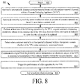
- Method 800 for causing certain operations to be performed by a VPA (e.g., VPA 200 of FIG. 2 ).
- VPA e.g., VPA 200 of FIG. 2
- Method 800 can include more or less steps than those shown in FIG. 8 .
- the VPA may have an automatic dispensing feature.
- method 800 may comprise optional steps 804-808. If the VPA does not have such an automatic dispensing feature, then method 800 can be absent of optional steps 804-808.
- step 804 container material is automatically dispensed from a roll of container material disposed in the VPA.
- step 806 a proximity sensor mechanism detects when an amount of container material contained on the roll is at or below a certain level. When such detection is made (as shown by step 808 ), at least one of the following operations can be performed by the VPA: suspend automatic dispensing operations; release a lock locking a lid of the VPA in a closed position; and output an indicator to a user that the roll needs to be replaced.
- the proximity sensor mechanism can perform other detection operations, as shown by step 810.
- the proximity sensor mechanism detects when container material is at least partially disposed within a transparent vacuum chamber of the VPA using a proximity sensor mechanism. This detection can be performed in response to a lid of the VPA being locked in a closed position.
- a signal is communicated from the proximity sensor mechanism to an electronic circuit of the VPA in response to the detection of the container material within the vacuum chamber. Thereafter, the performance of a first operation by the VPA is triggered, as shown by step 814.
- the first operation can be selected from the group comprising at least one of: mechanical clamping operations to clamp the container material in position; vacuum operations to extract fluid from within a container defined by the container material; heat sealing operations to create a heat seal along an open end of the container; lock releasing operations to allow actuation of a cutting device; and lowering operations to transition a cutting device from a retracted position into a cutting position.
- step 816 is performed where method 800 ends or other processing is performed.
- the proximity sensor mechanism may be disposed within the VPA at a location (1) between a roll of container material and a vacuum trough or (2) between a front panel and the vacuum trough.
- the proximity sensor mechanism can comprise: an emitter configured to emit light in proximity to and in a direction towards a vacuum chamber of the VPA; and a detector configured to detect the light reflected from the container material disposed in the VPA
Landscapes
- Engineering & Computer Science (AREA)
- Mechanical Engineering (AREA)
- Chemical & Material Sciences (AREA)
- Dispersion Chemistry (AREA)
- Packages (AREA)
- Vacuum Packaging (AREA)
Claims (10)
- Procédé pour faire exécuter certaines opérations par une emballeuse sous vide (« VPA »), comprenant les étapes consistant à :détecter quand un matériau formant contenant souple est disposé, au moins partiellement, dans une chambre à vide de la VPA sans contact physique avec le matériau formant contenant souple, en utilisant un mécanisme de capteur de proximité (460, 462) ;communiquer un signal provenant du mécanisme de capteur de proximité (460, 462) à un circuit électronique (504) de la VPA (200), en réponse à la détection du matériau formant contenant souple à l'intérieur de la chambre à vide ;déclencher l'exécution d'une première opération par la VPA (200), en réponse à la réception du signal par le circuit électronique (504), où la première opération est choisie dans le groupe comprenant des opérations de serrage mécanique pour fixer en place le matériau formant contenant souple, des opérations d'aspiration pour extraire un fluide de l'intérieur d'un contenant défini par le matériau formant contenant souple, et des opérations de thermoscellage pour créer un joint thermique le long d'une extrémité ouverte d'un contenant ;caractérisé en ce quele mécanisme de capteur de proximité (460, 462) détecte quand une quantité de matériau formant contenant souple contenue dans un rouleau (304) disposé à l'intérieur de la VPA (200), est égale ou inférieure à un certain niveau.
- Procédé selon la revendication 1, dans lequel l'étape de détection est exécutée en réponse au verrouillage d'un couvercle (202) de la VPA en position fermée.
- Procédé selon la revendication 1, comportant en outre l'étape consistant à
exécuter au moins l'une des opérations suivantes, en réponse à la détection du fait que la quantité de matériau formant contenant souple contenue dans le rouleau (304), est égale ou inférieure audit certain niveau :la suspension d'opérations de distribution automatique ; etla libération d'un verrou verrouillant un couvercle (202) de la VPA (200) en position fermée. - Procédé selon la revendication 1, dans lequel le groupe dans lequel la première opération est choisie comprend en outre au moins l'une parmi :des opérations de libération de verrou pour permettre l'actionnement d'un dispositif de coupe (204) ; etdes opérations d'abaissement pour faire passer un dispositif de coupe (204) d'une position rétractée en position de coupe.
- Procédé selon la revendication 1, dans lequel le mécanisme de capteur de proximité (460, 462) est disposé à l'intérieur de la VPA (200) à un emplacement (1) entre un rouleau (304) de matériau formant contenant et une auge à vide ou (2) entre un panneau avant et l'auge à vide.
- Procédé selon la revendication 1, comportant en outre l'étape consistant à émettre une lumière à proximité et en direction d'une chambre à vide de la VPA (200), et à détecter la lumière réfléchie par le matériau formant contenant disposé dans la VPA (200).
- Emballeuse sous vide (« VPA »), comprenant :un mécanisme de capteur de proximité (460, 462) configuré pour (1) détecter quand un matériau formant contenant souple est disposé, au moins partiellement, à l'intérieur d'une chambre à vide de la VPA sans contact physique avec le matériau formant contenant souple et (2) communiquer un signal à un circuit électronique (504) de la VPA (200) en réponse à la détection du matériau formant contenant souple à l'intérieur de la chambre à vide ;le circuit électronique (504) configuré pour déclencher l'exécution d'une première opération par la VPA (200) en réponse à la réception du signal à partir du mécanisme de capteur de proximité (460, 462), où la première opération est choisie dans le groupe comprenant des opérations de serrage mécanique pour fixer en place le matériau formant contenant, des opérations d'aspiration pour extraire un fluide de l'intérieur d'un contenant défini par le matériau formant contenant souple, et des opérations de thermoscellage pour créer un joint thermique le long d'une extrémité ouverte du contenant ;caractérisé en ce quele mécanisme de capteur de proximité (460, 462) est en outre configuré pour détecter quand une quantité de matériau formant contenant souple contenue dans un rouleau (304) disposé à l'intérieur de la VPA, (200) est égale ou inférieure à un certain niveau
- VPA (200) selon la revendication 7, dans laquelle le mécanisme de capteur de proximité (460, 462) exécute des opérations de détection en réponse au verrouillage d'un couvercle (202) de la VPA (200) en position fermée.
- VPA (200) selon la revendication 7, dans laquelle le circuit électronique (504) exécute au moins l'une des opérations suivantes, en réponse à la détection du fait que la quantité de matériau formant contenant souple contenue dans le rouleau (304), est égale ou inférieure audit certain niveau :la suspension d'opérations de distribution automatique ; etla libération d'un verrou verrouillant un couvercle (202) de la VPA (200) en position fermée.
- VPA (200) selon la revendication 7, dans laquelle le groupe dans lequel la première opération est choisie comprend en outre au moins l'une parmi :des opérations de libération de verrou pour permettre l'actionnement d'un dispositif de coupe (204) ; etdes opérations d'abaissement pour faire passer un dispositif de coupe (204) d'une position rétractée en position de coupe.
Applications Claiming Priority (2)
| Application Number | Priority Date | Filing Date | Title |
|---|---|---|---|
| US201361757330P | 2013-01-28 | 2013-01-28 | |
| PCT/US2014/013356 WO2014117141A1 (fr) | 2013-01-28 | 2014-01-28 | Scelleuse à vide à détecteur de proximité à semi-conducteur |
Publications (3)
| Publication Number | Publication Date |
|---|---|
| EP2948378A1 EP2948378A1 (fr) | 2015-12-02 |
| EP2948378A4 EP2948378A4 (fr) | 2017-07-12 |
| EP2948378B1 true EP2948378B1 (fr) | 2020-07-22 |
Family
ID=51228131
Family Applications (1)
| Application Number | Title | Priority Date | Filing Date |
|---|---|---|---|
| EP14743299.1A Not-in-force EP2948378B1 (fr) | 2013-01-28 | 2014-01-28 | Scelleuse à vide à détecteur de proximité à semi-conducteur |
Country Status (4)
| Country | Link |
|---|---|
| US (1) | US10040589B2 (fr) |
| EP (1) | EP2948378B1 (fr) |
| CA (1) | CA2899425A1 (fr) |
| WO (1) | WO2014117141A1 (fr) |
Families Citing this family (14)
| Publication number | Priority date | Publication date | Assignee | Title |
|---|---|---|---|---|
| WO2016055598A1 (fr) * | 2014-10-10 | 2016-04-14 | Cryovac, Inc. | Appareil et procédé pour emballer un produit |
| EP3303152B1 (fr) * | 2015-06-05 | 2020-09-02 | Sunbeam Products, Inc. | Appareil de stockage d'aliments |
| USD854065S1 (en) * | 2017-06-16 | 2019-07-16 | Sunbeam Products, Inc. | Vacuum sealer |
| US10822130B2 (en) * | 2017-06-21 | 2020-11-03 | Bonsen Electronics Limited | Household vacuum sealer and bag-cutting sealing method |
| CN107161383A (zh) * | 2017-07-05 | 2017-09-15 | 贵州大学 | 一种真空包装机机盖闭合限位装置 |
| USD854594S1 (en) * | 2017-10-11 | 2019-07-23 | The Metal Ware Corporation | Vacuum sealer |
| USD871470S1 (en) * | 2017-10-20 | 2019-12-31 | Shenzhen Green Electrical Appliance Co., Ltd | Vacuum sealer |
| US11174088B2 (en) * | 2018-03-07 | 2021-11-16 | Sunbeam Products, Inc. | Vacuum packaging and sealing appliance |
| USD881245S1 (en) * | 2018-03-08 | 2020-04-14 | Zhejiang Qunhai Electronic Technology Co., Ltd. | Vacuum sealer |
| CN109649730B (zh) * | 2019-01-03 | 2021-06-25 | 东莞市盈尔电器有限公司 | 一种多功能真空封口机 |
| US20220002063A1 (en) * | 2019-02-09 | 2022-01-06 | Brian Keith McKinnon | Cooler System |
| CN112937987A (zh) * | 2021-02-10 | 2021-06-11 | 广州亚俊氏电器有限公司 | 一种多功能真空包装机 |
| CN219821861U (zh) * | 2023-03-31 | 2023-10-13 | 中山市小薯电器科技有限公司 | 一种真空封口机 |
| US12145758B1 (en) * | 2024-06-03 | 2024-11-19 | Bigland Electric Appliance Co., Ltd. | Household vacuum sealer |
Citations (1)
| Publication number | Priority date | Publication date | Assignee | Title |
|---|---|---|---|---|
| US20100095638A1 (en) * | 2008-09-25 | 2010-04-22 | Zakowski Joseph W | Vacuum sealing appliance |
Family Cites Families (21)
| Publication number | Priority date | Publication date | Assignee | Title |
|---|---|---|---|---|
| US3318066A (en) * | 1962-12-29 | 1967-05-09 | G D Sas Di Enzo Seragnoli & Ar | Device for replacing the rolls and jointing the band of cellophane or the like, as well as discarding the defective products in cellophanewrapping machines |
| US3869842A (en) * | 1973-08-06 | 1975-03-11 | Henry Verbeke | Bag sealing apparatus and method of use |
| US3995791A (en) * | 1975-07-09 | 1976-12-07 | Package Machinery Company | Continuous web supply system |
| US4098049A (en) * | 1976-12-29 | 1978-07-04 | Norfolk & Western Railway Company | Apparatus and methods for impregnating oil into a lubricating pad |
| US4996819A (en) * | 1989-05-30 | 1991-03-05 | W. A. Lane, Inc. | Film feed device for packaging machine |
| GB9016291D0 (en) * | 1990-07-25 | 1990-09-12 | Alden Timothy J | Sealing method and apparatus |
| IT1249668B (it) * | 1991-06-20 | 1995-03-09 | Cavanna Spa | Unita' per l'erogazione di materiale in foglio, ad esempio per l`erogazione di fogli di cartone o cartoncino in macchine confezionatrici automatiche. |
| JP2001048119A (ja) | 1999-08-02 | 2001-02-20 | Furukawa Mfg Co Ltd | 袋口のシール装置 |
| US20030046907A1 (en) * | 2001-08-08 | 2003-03-13 | Costello Anthony William | Packaging apparatus |
| US20050205455A1 (en) * | 2002-07-08 | 2005-09-22 | Harrison Howard R | Vacuum packaging system |
| US7302784B2 (en) | 2002-09-27 | 2007-12-04 | Depuy Products, Inc. | Vacuum packaging machine |
| US20050022473A1 (en) * | 2003-07-31 | 2005-02-03 | Small Steven D. | Removable drip trays and bag clamps for vacuum packaging appliances |
| KR100584863B1 (ko) * | 2004-08-10 | 2006-05-30 | 안준영 | 노즐장치 삽입형 진공포장 시스템 및 챔버삽입형 노즐장치 |
| CN101797983A (zh) * | 2005-01-12 | 2010-08-11 | 优诺沃有限公司 | 抽空和密封容器的方法和设备 |
| BRPI0912128A2 (pt) * | 2008-05-29 | 2015-11-03 | Atlantic Corp | sistemas para monitoração e controle de uso de materiais |
| US20110126986A1 (en) * | 2009-12-01 | 2011-06-02 | Po Ha Cheung | Easy-to-operate bag sealer |
| WO2011101190A1 (fr) * | 2010-02-19 | 2011-08-25 | Extru Sa | Dispositif de conditionnement sous vide, en particulier pour des aliments |
| US9457920B2 (en) * | 2011-06-17 | 2016-10-04 | Sunbeam Products, Inc. | Automated food saver machine |
| US20130340389A1 (en) * | 2012-06-25 | 2013-12-26 | Charles Harder | Storage bag having an identification feature |
| KR101235844B1 (ko) * | 2012-07-16 | 2013-02-22 | (주)씨에스이 | 가정용 및 차량용 겸용 진공포장기 |
| US9102493B2 (en) * | 2012-10-02 | 2015-08-11 | Lamus Enterprises Inc | Tape monitoring system |
-
2014
- 2014-01-28 WO PCT/US2014/013356 patent/WO2014117141A1/fr not_active Ceased
- 2014-01-28 EP EP14743299.1A patent/EP2948378B1/fr not_active Not-in-force
- 2014-01-28 US US14/763,935 patent/US10040589B2/en active Active
- 2014-01-28 CA CA2899425A patent/CA2899425A1/fr not_active Abandoned
Patent Citations (1)
| Publication number | Priority date | Publication date | Assignee | Title |
|---|---|---|---|---|
| US20100095638A1 (en) * | 2008-09-25 | 2010-04-22 | Zakowski Joseph W | Vacuum sealing appliance |
Also Published As
| Publication number | Publication date |
|---|---|
| EP2948378A1 (fr) | 2015-12-02 |
| CA2899425A1 (fr) | 2014-07-31 |
| WO2014117141A1 (fr) | 2014-07-31 |
| US10040589B2 (en) | 2018-08-07 |
| EP2948378A4 (fr) | 2017-07-12 |
| US20150367973A1 (en) | 2015-12-24 |
Similar Documents
| Publication | Publication Date | Title |
|---|---|---|
| EP2948378B1 (fr) | Scelleuse à vide à détecteur de proximité à semi-conducteur | |
| US20140196405A1 (en) | Vacuum Sealer with a Retractable Heater Bar | |
| US9676506B2 (en) | Vacuum packaging and sealing appliance with liquid detection | |
| US10351279B2 (en) | Vacuum packaging and sealing appliance with double seal | |
| CN103017441B (zh) | 具有抽真空装置的冰箱及其控制方法 | |
| US10501219B2 (en) | Combination chamber and external suction vacuum packaging machine | |
| US20150027089A1 (en) | Vacuum Packaging and Sealing Appliance with Cooling Fan | |
| US20050205455A1 (en) | Vacuum packaging system | |
| US20150329347A1 (en) | Systems and methods for receptacle auto fill using inductive sensing | |
| US12019062B2 (en) | Test paper box and intelligent toilet containing same | |
| US11753196B2 (en) | Vacuum sealer and method of sealing same | |
| US20210031956A1 (en) | Vacuum Sealing Appliance Including Vacuum Cycle With Transducer Feedback | |
| JPWO2022024506A5 (fr) | ||
| JP2020531372A (ja) | 粉体搬送容器 | |
| CA2845466A1 (fr) | Unite de scellement hermetique avec regle chauffante retractable | |
| CN105996846B (zh) | 一种干货储藏装置及该储藏装置的控制方法 | |
| US20170267431A1 (en) | Packaging with an antibacterial coating | |
| EP3009255B1 (fr) | Appareil de scellage et d'emballage sous vide avec ventilateur de refroidissement | |
| CN108639412B (zh) | 一种自助称重装置 | |
| CN110884729A (zh) | 一种基于生物检测的智能封口系统及其工作方法 | |
| CN113483967A (zh) | 一种用于物流的节能环保装备的检测装置及其检测方法 | |
| CN107804532B (zh) | 一种光电烟雾报警器自动打包检测线 | |
| US20160251137A1 (en) | Storage Container with Expandable Medium | |
| CN109523699A (zh) | 一种具有弹簧货道的售货机的出货装置及可靠出货方法 | |
| KR101720182B1 (ko) | 자동 진공 포장기 |
Legal Events
| Date | Code | Title | Description |
|---|---|---|---|
| PUAI | Public reference made under article 153(3) epc to a published international application that has entered the european phase |
Free format text: ORIGINAL CODE: 0009012 |
|
| 17P | Request for examination filed |
Effective date: 20150804 |
|
| AK | Designated contracting states |
Kind code of ref document: A1 Designated state(s): AL AT BE BG CH CY CZ DE DK EE ES FI FR GB GR HR HU IE IS IT LI LT LU LV MC MK MT NL NO PL PT RO RS SE SI SK SM TR |
|
| AX | Request for extension of the european patent |
Extension state: BA ME |
|
| DAX | Request for extension of the european patent (deleted) | ||
| RIC1 | Information provided on ipc code assigned before grant |
Ipc: B65B 51/10 20060101ALI20170228BHEP Ipc: B65B 57/00 20060101ALI20170228BHEP Ipc: B65B 31/02 20060101AFI20170228BHEP |
|
| A4 | Supplementary search report drawn up and despatched |
Effective date: 20170613 |
|
| RIC1 | Information provided on ipc code assigned before grant |
Ipc: B65B 57/00 20060101ALI20170607BHEP Ipc: B65B 51/10 20060101ALI20170607BHEP Ipc: B65B 31/02 20060101AFI20170607BHEP |
|
| STAA | Information on the status of an ep patent application or granted ep patent |
Free format text: STATUS: EXAMINATION IS IN PROGRESS |
|
| 17Q | First examination report despatched |
Effective date: 20180420 |
|
| GRAP | Despatch of communication of intention to grant a patent |
Free format text: ORIGINAL CODE: EPIDOSNIGR1 |
|
| STAA | Information on the status of an ep patent application or granted ep patent |
Free format text: STATUS: GRANT OF PATENT IS INTENDED |
|
| INTG | Intention to grant announced |
Effective date: 20200205 |
|
| GRAS | Grant fee paid |
Free format text: ORIGINAL CODE: EPIDOSNIGR3 |
|
| GRAA | (expected) grant |
Free format text: ORIGINAL CODE: 0009210 |
|
| STAA | Information on the status of an ep patent application or granted ep patent |
Free format text: STATUS: THE PATENT HAS BEEN GRANTED |
|
| AK | Designated contracting states |
Kind code of ref document: B1 Designated state(s): AL AT BE BG CH CY CZ DE DK EE ES FI FR GB GR HR HU IE IS IT LI LT LU LV MC MK MT NL NO PL PT RO RS SE SI SK SM TR |
|
| REG | Reference to a national code |
Ref country code: GB Ref legal event code: FG4D |
|
| REG | Reference to a national code |
Ref country code: CH Ref legal event code: EP |
|
| REG | Reference to a national code |
Ref country code: DE Ref legal event code: R096 Ref document number: 602014068009 Country of ref document: DE |
|
| REG | Reference to a national code |
Ref country code: AT Ref legal event code: REF Ref document number: 1293156 Country of ref document: AT Kind code of ref document: T Effective date: 20200815 |
|
| REG | Reference to a national code |
Ref country code: IE Ref legal event code: FG4D |
|
| REG | Reference to a national code |
Ref country code: LT Ref legal event code: MG4D |
|
| REG | Reference to a national code |
Ref country code: AT Ref legal event code: MK05 Ref document number: 1293156 Country of ref document: AT Kind code of ref document: T Effective date: 20200722 |
|
| PG25 | Lapsed in a contracting state [announced via postgrant information from national office to epo] |
Ref country code: PT Free format text: LAPSE BECAUSE OF FAILURE TO SUBMIT A TRANSLATION OF THE DESCRIPTION OR TO PAY THE FEE WITHIN THE PRESCRIBED TIME-LIMIT Effective date: 20201123 Ref country code: ES Free format text: LAPSE BECAUSE OF FAILURE TO SUBMIT A TRANSLATION OF THE DESCRIPTION OR TO PAY THE FEE WITHIN THE PRESCRIBED TIME-LIMIT Effective date: 20200722 Ref country code: LT Free format text: LAPSE BECAUSE OF FAILURE TO SUBMIT A TRANSLATION OF THE DESCRIPTION OR TO PAY THE FEE WITHIN THE PRESCRIBED TIME-LIMIT Effective date: 20200722 Ref country code: FI Free format text: LAPSE BECAUSE OF FAILURE TO SUBMIT A TRANSLATION OF THE DESCRIPTION OR TO PAY THE FEE WITHIN THE PRESCRIBED TIME-LIMIT Effective date: 20200722 Ref country code: HR Free format text: LAPSE BECAUSE OF FAILURE TO SUBMIT A TRANSLATION OF THE DESCRIPTION OR TO PAY THE FEE WITHIN THE PRESCRIBED TIME-LIMIT Effective date: 20200722 Ref country code: AT Free format text: LAPSE BECAUSE OF FAILURE TO SUBMIT A TRANSLATION OF THE DESCRIPTION OR TO PAY THE FEE WITHIN THE PRESCRIBED TIME-LIMIT Effective date: 20200722 Ref country code: GR Free format text: LAPSE BECAUSE OF FAILURE TO SUBMIT A TRANSLATION OF THE DESCRIPTION OR TO PAY THE FEE WITHIN THE PRESCRIBED TIME-LIMIT Effective date: 20201023 Ref country code: SE Free format text: LAPSE BECAUSE OF FAILURE TO SUBMIT A TRANSLATION OF THE DESCRIPTION OR TO PAY THE FEE WITHIN THE PRESCRIBED TIME-LIMIT Effective date: 20200722 Ref country code: NO Free format text: LAPSE BECAUSE OF FAILURE TO SUBMIT A TRANSLATION OF THE DESCRIPTION OR TO PAY THE FEE WITHIN THE PRESCRIBED TIME-LIMIT Effective date: 20201022 Ref country code: BG Free format text: LAPSE BECAUSE OF FAILURE TO SUBMIT A TRANSLATION OF THE DESCRIPTION OR TO PAY THE FEE WITHIN THE PRESCRIBED TIME-LIMIT Effective date: 20201022 |
|
| PG25 | Lapsed in a contracting state [announced via postgrant information from national office to epo] |
Ref country code: IS Free format text: LAPSE BECAUSE OF FAILURE TO SUBMIT A TRANSLATION OF THE DESCRIPTION OR TO PAY THE FEE WITHIN THE PRESCRIBED TIME-LIMIT Effective date: 20201122 Ref country code: RS Free format text: LAPSE BECAUSE OF FAILURE TO SUBMIT A TRANSLATION OF THE DESCRIPTION OR TO PAY THE FEE WITHIN THE PRESCRIBED TIME-LIMIT Effective date: 20200722 Ref country code: PL Free format text: LAPSE BECAUSE OF FAILURE TO SUBMIT A TRANSLATION OF THE DESCRIPTION OR TO PAY THE FEE WITHIN THE PRESCRIBED TIME-LIMIT Effective date: 20200722 Ref country code: LV Free format text: LAPSE BECAUSE OF FAILURE TO SUBMIT A TRANSLATION OF THE DESCRIPTION OR TO PAY THE FEE WITHIN THE PRESCRIBED TIME-LIMIT Effective date: 20200722 |
|
| PG25 | Lapsed in a contracting state [announced via postgrant information from national office to epo] |
Ref country code: NL Free format text: LAPSE BECAUSE OF FAILURE TO SUBMIT A TRANSLATION OF THE DESCRIPTION OR TO PAY THE FEE WITHIN THE PRESCRIBED TIME-LIMIT Effective date: 20200722 |
|
| REG | Reference to a national code |
Ref country code: DE Ref legal event code: R097 Ref document number: 602014068009 Country of ref document: DE |
|
| PG25 | Lapsed in a contracting state [announced via postgrant information from national office to epo] |
Ref country code: RO Free format text: LAPSE BECAUSE OF FAILURE TO SUBMIT A TRANSLATION OF THE DESCRIPTION OR TO PAY THE FEE WITHIN THE PRESCRIBED TIME-LIMIT Effective date: 20200722 Ref country code: SM Free format text: LAPSE BECAUSE OF FAILURE TO SUBMIT A TRANSLATION OF THE DESCRIPTION OR TO PAY THE FEE WITHIN THE PRESCRIBED TIME-LIMIT Effective date: 20200722 Ref country code: IT Free format text: LAPSE BECAUSE OF FAILURE TO SUBMIT A TRANSLATION OF THE DESCRIPTION OR TO PAY THE FEE WITHIN THE PRESCRIBED TIME-LIMIT Effective date: 20200722 Ref country code: DK Free format text: LAPSE BECAUSE OF FAILURE TO SUBMIT A TRANSLATION OF THE DESCRIPTION OR TO PAY THE FEE WITHIN THE PRESCRIBED TIME-LIMIT Effective date: 20200722 Ref country code: CZ Free format text: LAPSE BECAUSE OF FAILURE TO SUBMIT A TRANSLATION OF THE DESCRIPTION OR TO PAY THE FEE WITHIN THE PRESCRIBED TIME-LIMIT Effective date: 20200722 Ref country code: EE Free format text: LAPSE BECAUSE OF FAILURE TO SUBMIT A TRANSLATION OF THE DESCRIPTION OR TO PAY THE FEE WITHIN THE PRESCRIBED TIME-LIMIT Effective date: 20200722 |
|
| PLBE | No opposition filed within time limit |
Free format text: ORIGINAL CODE: 0009261 |
|
| STAA | Information on the status of an ep patent application or granted ep patent |
Free format text: STATUS: NO OPPOSITION FILED WITHIN TIME LIMIT |
|
| PG25 | Lapsed in a contracting state [announced via postgrant information from national office to epo] |
Ref country code: AL Free format text: LAPSE BECAUSE OF FAILURE TO SUBMIT A TRANSLATION OF THE DESCRIPTION OR TO PAY THE FEE WITHIN THE PRESCRIBED TIME-LIMIT Effective date: 20200722 |
|
| 26N | No opposition filed |
Effective date: 20210423 |
|
| PG25 | Lapsed in a contracting state [announced via postgrant information from national office to epo] |
Ref country code: SK Free format text: LAPSE BECAUSE OF FAILURE TO SUBMIT A TRANSLATION OF THE DESCRIPTION OR TO PAY THE FEE WITHIN THE PRESCRIBED TIME-LIMIT Effective date: 20200722 |
|
| REG | Reference to a national code |
Ref country code: DE Ref legal event code: R119 Ref document number: 602014068009 Country of ref document: DE |
|
| PG25 | Lapsed in a contracting state [announced via postgrant information from national office to epo] |
Ref country code: MC Free format text: LAPSE BECAUSE OF FAILURE TO SUBMIT A TRANSLATION OF THE DESCRIPTION OR TO PAY THE FEE WITHIN THE PRESCRIBED TIME-LIMIT Effective date: 20200722 Ref country code: SI Free format text: LAPSE BECAUSE OF FAILURE TO SUBMIT A TRANSLATION OF THE DESCRIPTION OR TO PAY THE FEE WITHIN THE PRESCRIBED TIME-LIMIT Effective date: 20200722 |
|
| REG | Reference to a national code |
Ref country code: CH Ref legal event code: PL |
|
| PG25 | Lapsed in a contracting state [announced via postgrant information from national office to epo] |
Ref country code: LU Free format text: LAPSE BECAUSE OF NON-PAYMENT OF DUE FEES Effective date: 20210128 |
|
| REG | Reference to a national code |
Ref country code: BE Ref legal event code: MM Effective date: 20210131 Ref country code: NL Ref legal event code: MP Effective date: 20200722 |
|
| PG25 | Lapsed in a contracting state [announced via postgrant information from national office to epo] |
Ref country code: DE Free format text: LAPSE BECAUSE OF NON-PAYMENT OF DUE FEES Effective date: 20210803 Ref country code: CH Free format text: LAPSE BECAUSE OF NON-PAYMENT OF DUE FEES Effective date: 20210131 Ref country code: LI Free format text: LAPSE BECAUSE OF NON-PAYMENT OF DUE FEES Effective date: 20210131 |
|
| PG25 | Lapsed in a contracting state [announced via postgrant information from national office to epo] |
Ref country code: IE Free format text: LAPSE BECAUSE OF NON-PAYMENT OF DUE FEES Effective date: 20210128 |
|
| PGFP | Annual fee paid to national office [announced via postgrant information from national office to epo] |
Ref country code: GB Payment date: 20220127 Year of fee payment: 9 |
|
| PGFP | Annual fee paid to national office [announced via postgrant information from national office to epo] |
Ref country code: FR Payment date: 20220125 Year of fee payment: 9 |
|
| PG25 | Lapsed in a contracting state [announced via postgrant information from national office to epo] |
Ref country code: BE Free format text: LAPSE BECAUSE OF NON-PAYMENT OF DUE FEES Effective date: 20210131 |
|
| PG25 | Lapsed in a contracting state [announced via postgrant information from national office to epo] |
Ref country code: HU Free format text: LAPSE BECAUSE OF FAILURE TO SUBMIT A TRANSLATION OF THE DESCRIPTION OR TO PAY THE FEE WITHIN THE PRESCRIBED TIME-LIMIT; INVALID AB INITIO Effective date: 20140128 |
|
| PG25 | Lapsed in a contracting state [announced via postgrant information from national office to epo] |
Ref country code: CY Free format text: LAPSE BECAUSE OF FAILURE TO SUBMIT A TRANSLATION OF THE DESCRIPTION OR TO PAY THE FEE WITHIN THE PRESCRIBED TIME-LIMIT Effective date: 20200722 |
|
| GBPC | Gb: european patent ceased through non-payment of renewal fee |
Effective date: 20230128 |
|
| PG25 | Lapsed in a contracting state [announced via postgrant information from national office to epo] |
Ref country code: GB Free format text: LAPSE BECAUSE OF NON-PAYMENT OF DUE FEES Effective date: 20230128 |
|
| PG25 | Lapsed in a contracting state [announced via postgrant information from national office to epo] |
Ref country code: FR Free format text: LAPSE BECAUSE OF NON-PAYMENT OF DUE FEES Effective date: 20230131 |
|
| PG25 | Lapsed in a contracting state [announced via postgrant information from national office to epo] |
Ref country code: MK Free format text: LAPSE BECAUSE OF FAILURE TO SUBMIT A TRANSLATION OF THE DESCRIPTION OR TO PAY THE FEE WITHIN THE PRESCRIBED TIME-LIMIT Effective date: 20200722 |
|
| PG25 | Lapsed in a contracting state [announced via postgrant information from national office to epo] |
Ref country code: MT Free format text: LAPSE BECAUSE OF FAILURE TO SUBMIT A TRANSLATION OF THE DESCRIPTION OR TO PAY THE FEE WITHIN THE PRESCRIBED TIME-LIMIT Effective date: 20200722 |
|
| PG25 | Lapsed in a contracting state [announced via postgrant information from national office to epo] |
Ref country code: TR Free format text: LAPSE BECAUSE OF FAILURE TO SUBMIT A TRANSLATION OF THE DESCRIPTION OR TO PAY THE FEE WITHIN THE PRESCRIBED TIME-LIMIT Effective date: 20200722 |