EP2948404B1 - Dispositif de levage et de pivotement - Google Patents
Dispositif de levage et de pivotement Download PDFInfo
- Publication number
- EP2948404B1 EP2948404B1 EP13795749.4A EP13795749A EP2948404B1 EP 2948404 B1 EP2948404 B1 EP 2948404B1 EP 13795749 A EP13795749 A EP 13795749A EP 2948404 B1 EP2948404 B1 EP 2948404B1
- Authority
- EP
- European Patent Office
- Prior art keywords
- load
- lifting
- pivoting
- arm
- main body
- Prior art date
- Legal status (The legal status is an assumption and is not a legal conclusion. Google has not performed a legal analysis and makes no representation as to the accuracy of the status listed.)
- Active
Links
Images




Classifications
-
- B—PERFORMING OPERATIONS; TRANSPORTING
- B66—HOISTING; LIFTING; HAULING
- B66C—CRANES; LOAD-ENGAGING ELEMENTS OR DEVICES FOR CRANES, CAPSTANS, WINCHES, OR TACKLES
- B66C1/00—Load-engaging elements or devices attached to lifting or lowering gear of cranes or adapted for connection therewith for transmitting lifting forces to articles or groups of articles
- B66C1/02—Load-engaging elements or devices attached to lifting or lowering gear of cranes or adapted for connection therewith for transmitting lifting forces to articles or groups of articles by suction means
- B66C1/0237—Multiple lifting units; More than one suction area
-
- B—PERFORMING OPERATIONS; TRANSPORTING
- B66—HOISTING; LIFTING; HAULING
- B66C—CRANES; LOAD-ENGAGING ELEMENTS OR DEVICES FOR CRANES, CAPSTANS, WINCHES, OR TACKLES
- B66C1/00—Load-engaging elements or devices attached to lifting or lowering gear of cranes or adapted for connection therewith for transmitting lifting forces to articles or groups of articles
- B66C1/10—Load-engaging elements or devices attached to lifting or lowering gear of cranes or adapted for connection therewith for transmitting lifting forces to articles or groups of articles by mechanical means
-
- B—PERFORMING OPERATIONS; TRANSPORTING
- B66—HOISTING; LIFTING; HAULING
- B66C—CRANES; LOAD-ENGAGING ELEMENTS OR DEVICES FOR CRANES, CAPSTANS, WINCHES, OR TACKLES
- B66C1/00—Load-engaging elements or devices attached to lifting or lowering gear of cranes or adapted for connection therewith for transmitting lifting forces to articles or groups of articles
- B66C1/10—Load-engaging elements or devices attached to lifting or lowering gear of cranes or adapted for connection therewith for transmitting lifting forces to articles or groups of articles by mechanical means
- B66C1/108—Load-engaging elements or devices attached to lifting or lowering gear of cranes or adapted for connection therewith for transmitting lifting forces to articles or groups of articles by mechanical means for lifting parts of wind turbines
-
- B—PERFORMING OPERATIONS; TRANSPORTING
- B66—HOISTING; LIFTING; HAULING
- B66C—CRANES; LOAD-ENGAGING ELEMENTS OR DEVICES FOR CRANES, CAPSTANS, WINCHES, OR TACKLES
- B66C13/00—Other constructional features or details
- B66C13/04—Auxiliary devices for controlling movements of suspended loads, or preventing cable slack
- B66C13/08—Auxiliary devices for controlling movements of suspended loads, or preventing cable slack for depositing loads in desired attitudes or positions
Definitions
- the invention relates to a lifting and pivoting device according to the preamble of claim 1, for lifting and pivoting a load, in particular a rotor bar and a load lifting system comprising at least one lifting and pivoting device.
- the individual segments are referred to as belt, upper shell, lower shell and webs.
- the cross section of the finished rotor blades generally two main webs perpendicular to an upper and a lower belt segment, and up to two smaller so-called Endkanten- or nasenkantengurte and webs.
- the main webs and straps form a cross-sectionally at least partially diamond-shaped basic framework of a rotor blade.
- the upper shell and the lower shell, which form the outer skin of the rotor blade, are supported on this basic framework or on the upper and lower belt segments.
- the individual segments are made of a Balsaholzkern, which are braided with fabric mats and then penetrated under exclusion of air with epoxy resin. This process is referred to as a vacuum infusion process. After curing of the epoxy resin, the individual segments of the rotor blades are then released from their shape.
- the designated as rotor webs or main webs reinforcing segments of a rotor blade which are arranged in the interior of the rotor blade as part of the diamond-shaped skeleton, are usually made lying and must therefore be placed after removal from the mold. For this purpose, they are usually attached to a mechanical gripper, which raises the rotor segments or the rotor webs on one side or by means of lifting straps in the vertical position .. In this one-sided lifting the rotor segments are partially pulled over the ground, whereby the components can be affected.
- the C- or T-shaped adhesive tabs of the webs are particularly sensitive.
- the demoulded rotor bars are then positioned with a special web setting device for final assembly of the rotor blades in the main mold. Due to the enormous size of the wind turbines, the segments of the rotor blades take up a lot of space.
- the invention is therefore based on the object a lifting and pivoting device for lifting and pivoting a load, in particular a rotor bar, to provide, with which the load can be raised and pivoted in a reliable and safe manner.
- the lifting and pivoting device has a pivot arm for attaching the load, a base body, a relative to the body axially displaceable displacement device which is pivotally connected to the pivot arm, and at least one lever arm connected to the base body and the pivot arm such is that the pivot arm is pivoted in displacement of the displacement device relative to the base body.
- the swivel arm has a plurality of connection or bearing points.
- the pivot arm is connected to the displacement device, on the other hand, the pivot arm is connected to the lever arm.
- the swivel arm which is pivotally connected to the displacement device and which is preferably connected to the displacement device in the middle of the swivel arm, then moves around the connection point between the swivel arm and the displacement device on the one hand and around the connection point between the swivel arm and the lever arm on the other hand. This can be done a superimposed lifting and pivoting movement.
- the lifting and pivoting device advantageously a load.
- This is particularly advantageous for the lifting and / or pivoting of the rotor webs mentioned above, wherein the rotor webs can then be torn out of their shape, lifted and pivoted.
- the swivel arm is pivotable by about 90 °, in particular between a first, at least almost horizontal position in a second, at least almost vertical position.
- pivoting about 90 ° can also be realized a lifting function, since the load is not pivoted about a constant pivot axis, but at the same time a superimposed lifting movement can take place in the vertical direction.
- bearings are preferably arranged in the respective end regions of the pivot arm, but preferably in the outer third.
- the bearings can be formed, for example, as a profile strips with holes, which are then connected to the swivel arm, for example. By screwing.
- an eyelet as a bearing.
- To connect the lever arm with the swivel arm at the bearing point can be provided, for example, provide a bolt with Sich ceremoniesssplint. By such a bolt, a quick transfer between the bearings can be made possible.
- a further advantageous embodiment provides that at least one, preferably two vacuum suction pads are arranged on the swivel arm for holding the load.
- These vacuum suction pads can advantageously be arranged in the region of the ends of the pivot arm on the side facing away from the lever arm side of the pivot arm.
- the displacement device comprises a linear drive, in particular a toothed rack, and a pinion, which can be driven directly or indirectly by an electric motor via a gear, and which engages with the toothed rack.
- the rack may have a stop, so that the pinion can not move the rack over the stop.
- the displacement device is also designed as a linear direct drive, ball screw, roller screw, pneumatic cylinder or hydraulic cylinder. Regardless of the design of the linear drive, however, it is important that in each case a part of the linear drive is fixedly connected to the base body and another part of the linear drive which is designed to be movable relative to the fixed part fixed to the main body, with the pivot arm.
- the rack is arranged on a designed as a double-T profile rail of the displacement device.
- the rail may have an additional stop, which in addition to an optionally on the Rack arranged stop can prevent falling out of the rack or the rail down.
- the base body has a stationary carriage, wherein the rail of the displacement device is guided in the carriage and / or stored.
- the carriage may preferably have a plurality of bearing rollers for guiding and / or supporting the rail, which are made of polyamide, for example.
- the rail When forming the rail as a double-T-profile, this consists of two transverse webs with a perpendicularly extending between the two transverse webs central web.
- two bearing rollers are provided on a transverse web on the side facing away from the central web and on the same crosspiece two bearing rollers on the side facing the central web.
- a particularly advantageous embodiment of the invention provides that at the ends of the pivoting arm securing claws are provided which are displaceable with the load held along a longitudinal axis of the pivot arm in a securing position and engage behind the load at least in sections in the securing position.
- the securing claws can be at least partially C-shaped. A displacement of the securing claws in the securing position can be done by moving the securing claws towards the center of the swing arm.
- the swivel arm or the securing claws have a slot in which bolts fixed to the securing claws or to the swivel arm are guided.
- a displacement of the securing claws along a longitudinal axis of the pivot arm by sliding the bolt in the slot can be done.
- the safety claws automated, that is, for example, driven to move by pneumatic cylinder, hydraulic cylinder or by means of an electric motor in its safety position.
- a further advantageous embodiment of the invention provides that the base body has at least one transverse to the direction of action of the displacement device extending rail, wherein at the ends of the rail mounting portions are provided for attaching the body to a crane boom.
- the fastening sections can be adapted to the respective crane jib in such a way that the fastening sections can be fastened with their cross section to the cross section of the respective profile of the crane jib.
- a lifting device for lifting and pivoting a load comprising at least one device according to one of claims 1 to 9 and a crane jib for fastening the at least one device.
- a lifting device thus comprises a crane boom and at least one, in particular a plurality of lifting and pivoting devices attached thereto.
- the lifting device has additional vacuum suction pads for holding the load.
- additional vacuum suction pad is therefore particularly advantageous because even if the vacuum suction pads of the lifting and pivoting device, for example. Due to geometric conditions can not be attached to the load, the additional vacuum suction pad, which are part of the lifting equipment , For lifting or pivoting the load can be attached to the load.
- screws can be secured, for example, by lock nuts or by Loctite screw lock, whereas it can be provided that the bolts can be secured in their position by means of snap rings or cotter pins.
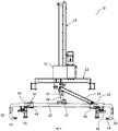
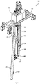
- FIGS. 1 to 4 show a lifting and pivoting device 10 according to the invention.
- the lifting and pivoting device 10 comprises a base body 12, as well as a relative to the base body 12 axially displaceable vertically displacement device 14.
- the base body 12 includes a stationary slide 16, which over in FIG. 2 clearly visible screws or rivets 18 is connected to two mutually parallel double T-profiles 20.
- the lifting and pivoting device 10 further comprises a pivoting arm 22, which is pivotally connected to the displacement device 14.
- the lifting and pivoting device 10 further comprises a lever arm 24 which is connected to the base body 12 and the carriage 16 and the Swivel arm 22 is connected such that the pivot arm 22 is pivoted axially displaceable with respect to the base body 12 during displacement of the displacement device 14.
- the displacement device 14 is designed as a linear drive, in particular as a toothed rack 26 with a pinion 32 drivable indirectly by an electric motor 28 via a gear 30.
- the pinion 32 is in engagement with the rack 26 and meshes with the teeth of the rack 26.
- the displacement device 14 and the rack 26 is along a longitudinal axis 34 relative to the base body 12 and the carriage 16 displaced.
- the rack 26 is arranged on a rail 36 designed as a double T-profile.
- the rail 36 of the displacement device 14 is pivotally connected to the pivot arm 22 at its end facing away from the electric motor 28 with a T-shaped intermediate piece 38 arranged on the pivot arm 22 via a rotary or pivot bearing 40.
- the intermediate piece 38 has for connection to the pivot arm 22 on a flat mounting plate 42, which is bolted to the formed as a profile rail pivot arm 22 by means of screws 44.
- the intermediate piece 38 is arranged centrally on the pivot arm 22.
- two vacuum suction pads 46 are further provided in the region of the ends 48 of the pivot arm. These vacuum suction pads 46 preferably operate on the Bernoulli principle, so that they can generate negative pressure when connected to a compressed air line.
- the suction plates can also be connected to a pump via a vacuum suction line.
- the gripper surface of the vacuum suction pads 46 is formed oval. However, it is also conceivable that the gripper surface is round or square.
- securing claws 50 are provided at the ends 48 of the pivoting arm 22, in addition to the vacuum suction pads 46. These securing claws 50 are displaceable with the load held along a longitudinal axis 52 of the pivot arm towards the center of the pivot arm 22 in a securing position.
- the safety claws 50 are at least Partially C-shaped and engaging behind in the securing position the gripped or held on the vacuum suction pad 46 load at least in sections with their, parallel to the pivot arm 22 extending away from the pivot arm 22 webs 54.
- the safety claws 50 have a slot 56 in which a not shown in the figures bolt of the swing arm is guided.
- the securing claws 50 can therefore be displaced by means of the elongated hole 56 toward the center of the pivoting arm 22.
- the securing claws 50 are secured in their securing position, for example by securing bolts or securing splines.
- the securing claws 50 may be profile-shaped, in particular rectangular, in cross-section, wherein the securing claws 50 have a connecting portion 60, on which the securing claws 50 are connected to the pivot arm 22. At the connecting portions 60, the securing claws 50 preferably have a profile which is the same or at least similar to the profile of the pivoting arm 22.
- the bearings 62 are in each case in the outer, that is, the ends 48 of the pivot arm 22 facing third of the pivot arm 22.
- the bearings 62 may be formed, for example, as a profile strips with holes. However, it is also conceivable to form the bearings as a welded eyelet.
- the pivot arm 22 is connected to the respective upper bearing point 62 with the lever arm 24.
- FIG. 2 shows an enlarged section of the illustration according to FIG. 1 ,
- the lever arm 24 comprises two Hebelarmancen 64.
- a Hebelarmance 64 is provided on each side of the rack 26 and the rail 36 and arranged on the one hand rotatably on the stationary carriage 16 and on the bearing point 62 of the pivot arm.
- the stationary carriage 16 screwed to the double-T profiles 20 of the base body 12 has a plurality of bearing rollers 66. Through these bearing rollers designed as a double-T-carrier rail 36 of the displacement device 14 is guided.
- the double-T-beam has two transverse webs 68 and a central web 70 extending perpendicularly between the two transverse webs 68.
- the transverse to the longitudinal axis 34 of the displacement device 14 extending double T-profiles 20 of the body 12 are connected at their ends in each case by a cross member 74 with each other.
- fastening portions 76 are provided, which are formed by fixed to the cross members 74 plates 78 with holes 80 and through into the holes 80 of the plates 78 engaging screws 82 and counter plates 84.
- FIGS. 1 and 2 show the lifting and pivoting device 10 in its pivoted position in the direction of - 90 °.
- FIG. 3 shows the lifting and pivoting device 10 according to FIGS. 1 and 2 in the basic position. If now the lifting and pivoting device 10 in the basic position according to FIG. 3 is to be pivoted, the rack 26 is moved by the drivable by the electric motor 28 pinion 32 in the direction of arrow 86 along its longitudinal axis 34 upwards. This results in a superimposed lifting and pivoting movement on the pivot bearing 40.
- the pivot arm 22 on the lever arm 24 thus the pivot arm 22 of its nearly vertical, in FIG. 1 shown position in his in FIG. 3 pivoted, almost horizontal position pivoted.
- the lifting and pivoting device in the in FIG. 3 shown basic position can be reduced to the load, not shown.
- the displacement device 14 and the rack 26 relative to the base body 12 can be moved and in their in the FIGS. 1 and 2 shown pivoting position can be pivoted in - 90 °.
- FIG. 4 shows the lifting and pivoting device in a + 90 ° tilted representation.
- the lever arm 24 is not as in FIGS. 1 and 2 shown disposed on the pivot bearing 40 from right bearing point 62. Rather, the lever arm 24 is connected to the pivot arm 22 at the pivot bearing 40 from the left bearing 62.
- the lifting and pivoting device 10 are rebuilt so that not only a pivoting loads in - 90 ° direction, but also a pivoting of loads in the + 90 ° direction is made possible.
- FIGS. 5a and 5b show a lifting device 88, which includes a plurality of lifting and pivoting devices 10.
- the lifting device 88 further comprises a truss-like crane boom 90.
- This crane boom 90 is connected at its two mutually parallel and rectangular shaped crane profiles 92 with the mounting portions 76 of the lifting and pivoting devices 10.
- the load lifting system 88 further comprises additional vacuum suction pads 94, which are provided in addition to the vacuum suction pads 46 of the lifting and pivoting devices 10.
- the crane boom 90 further has on its upper side a crane eye 96, on which the crane boom 90 can be gripped, for example with a hook, not shown.
- FIG. 5a shows the lifting device 88 with a gripped load in the form of a rotor bar 98 in the basic position.
- FIG. 5b shows the lifting device 88 in the pivoted position.
- the additional vacuum suction pads 94 are clearly visible. These can be used especially when the profile of the load, for example the rotor webs 98 changes along the longitudinal extent and the vacuum suction pad 46 of the lifting and pivoting devices 10 can not be attached to the load or the rotor bar 98 due to geometric conditions. Even with the lifting device 88, pivoting in the + and - 90 ° directions is possible. Analogous to the FIGS. 1 to 4 For this purpose, the lever arms 24 of the lifting and pivoting devices 10 must also be rebuilt at the bearings 62.
Landscapes
- Engineering & Computer Science (AREA)
- Mechanical Engineering (AREA)
- Load-Engaging Elements For Cranes (AREA)
- Jib Cranes (AREA)
Claims (11)
- Dispositif de levage et de pivotement (10) destiné à lever et à pivoter une charge, en particulier une entretoise de rotor (98), comprenant un bras pivotant (22) pour fixer ladite charge, un corps de base (12), un dispositif de déplacement (14) qui peut être déplacé axialement verticalement par rapport au corps de base (12) et qui est relié à pivotement au bras pivotant (22), et au moins un bras de levier (24) qui est relié au corps de base (12) et au bras pivotant (22) de telle manière que le bras pivotant (22) est amené à pivoter lorsque le dispositif de déplacement (14) est déplacé par rapport au corps de base (12), caractérisé par le fait que sur ledit bras pivotant (22) sont prévus plusieurs points de support (62) pour le relier au bras de levier (24).
- Dispositif (10) selon la revendication 1, caractérisé par le fait que ledit bras pivotant (22) peut pivoter de 90° à peu près, en particulier depuis une première position au moins presque horizontale dans une deuxième position au moins presque verticale.
- Dispositif (10) selon la revendication 1 ou 2, caractérisé par le fait que lesdits plusieurs points de support (62) sont réalisés pour la fixation amovible dudit bras de levier (24).
- Dispositif (10) selon l'une quelconque des revendications précédentes, caractérisé par le fait qu'au moins une, de préférence deux ventouses à vide (46) destinées à tenir la charge sont disposées sur ledit bras pivotant (22).
- Dispositif (10) selon l'une quelconque des revendications précédentes, caractérisé par le fait que ledit dispositif de déplacement (14) comprend un entraînement linéaire, en particulier une crémaillère (26) et un pignon (32) qui peut être entraîné par un moteur électrique (28) directement ou indirectement via un engrenage (30) et qui est en prise avec ladite crémaillère (26).
- Dispositif (10) selon la revendication 5, caractérisé par le fait que la crémaillère (26) de l'entraînement linéaire est disposée sur un rail (36) du dispositif de déplacement (14), qui est réalisé en tant que profilé en double T.
- Dispositif (10) selon la revendication 6, caractérisé par le fait que ledit corps de base (12) présente un chariot (16) stationnaire, dans lequel ledit rail (36) du dispositif de déplacement est guidé et/ou logé dans le chariot (16).
- Dispositif (10) selon l'une quelconque des revendications précédentes, caractérisé par le fait que des griffes de sûreté (50) sont prévues aux extrémités (48) du bras pivotant (22), qui, lorsque la charge est tenue, peuvent être déplacées le long d'un axe longitudinal (52) du bras pivotant (22) dans une position de sûreté et qui s'engagent, dans la position de sûreté, au moins par portions derrière la charge.
- Dispositif (10) selon l'une quelconque des revendications précédentes, caractérisé par le fait que ledit corps de base (12) présente au moins un rail profilé (20) s'étendant transversalement à la direction d'action du dispositif de déplacement (14), dans lequel des portions de fixation (76) destinées à fixer le corps de base (12) sur une flèche (90) sont prévues aux extrémités du rail profilé (20).
- Installation de levage de charge (88) destinée à lever et à pivoter une charge, en particulier une entretoise de rotor (98), comprenant au moins un dispositif (10) selon l'une quelconque des revendications précédentes et une flèche (90) destinée à fixer ledit au moins un dispositif (10).
- Installation de levage de charge (88) selon la revendication 10, caractérisée par le fait que l'installation de levage de charge (88) présente des ventouses à vide (94) supplémentaires pour tenir la charge.
Applications Claiming Priority (2)
| Application Number | Priority Date | Filing Date | Title |
|---|---|---|---|
| DE102013201017.6A DE102013201017B4 (de) | 2013-01-23 | 2013-01-23 | Hebe-und Schwenkvorrichtung |
| PCT/EP2013/074628 WO2014114386A1 (fr) | 2013-01-23 | 2013-11-25 | Dispositif de levage et de pivotement |
Publications (2)
| Publication Number | Publication Date |
|---|---|
| EP2948404A1 EP2948404A1 (fr) | 2015-12-02 |
| EP2948404B1 true EP2948404B1 (fr) | 2017-04-19 |
Family
ID=49667147
Family Applications (1)
| Application Number | Title | Priority Date | Filing Date |
|---|---|---|---|
| EP13795749.4A Active EP2948404B1 (fr) | 2013-01-23 | 2013-11-25 | Dispositif de levage et de pivotement |
Country Status (4)
| Country | Link |
|---|---|
| EP (1) | EP2948404B1 (fr) |
| DE (1) | DE102013201017B4 (fr) |
| ES (1) | ES2625054T3 (fr) |
| WO (1) | WO2014114386A1 (fr) |
Families Citing this family (4)
| Publication number | Priority date | Publication date | Assignee | Title |
|---|---|---|---|---|
| CN105525308B (zh) * | 2016-01-30 | 2017-09-22 | 中国有色(沈阳)冶金机械有限公司 | 一种槽罩板抓取装置 |
| DE102017102368A1 (de) * | 2017-02-07 | 2018-08-09 | J. Schmalz Gmbh | Vorrichtung zum Handhaben von Stegen sowie Verfahren zum Handhaben von Stegen für Rotorblätter |
| CN108675109B (zh) * | 2018-04-24 | 2024-03-26 | 太仓希拓自动化设备有限公司 | 一种用于风能设备中的安全型吊装装置及其工作方法 |
| CN119750350B (zh) * | 2024-12-05 | 2026-03-03 | 航天海鹰(镇江)特种材料有限公司 | 一种大尺寸无人机机身外蒙皮定位吊运装配装置及其使用方法 |
Citations (1)
| Publication number | Priority date | Publication date | Assignee | Title |
|---|---|---|---|---|
| DE7015758U (de) * | 1970-04-27 | 1970-09-03 | Oespag Oesterr Sanitaer | Einrichtung zum transport von formen |
Family Cites Families (6)
| Publication number | Priority date | Publication date | Assignee | Title |
|---|---|---|---|---|
| US6733058B1 (en) * | 1999-09-20 | 2004-05-11 | Himecs Corp. | Winding roll lifting device with adjustable supporting arm and chuck member |
| DE102010004857A1 (de) * | 2010-01-18 | 2011-07-21 | KONECRANES Lifting Systems GmbH, 40789 | Vorrichtung zum Wenden von großflächigen Werkstücken |
| DE102010006203A1 (de) | 2010-01-29 | 2011-08-04 | Vetter Krantechnik GmbH, 57080 | Lastwendegerät |
| DE202011100044U1 (de) * | 2011-04-29 | 2012-05-02 | Bystronic Armatec Gmbh | Handhabungsvorrichtung mit einer in vertikaler Richtung schwenkbaren Bedieneinheit für eine Glasplatte, insbesondere ein mehrlagiges Glaspaket |
| CN202279615U (zh) * | 2011-09-28 | 2012-06-20 | 深圳市创思泰科技有限公司 | 气动真空前后翻转吸盘机及其应用设备 |
| CN202625583U (zh) * | 2012-05-07 | 2012-12-26 | 济南吉利汽车有限公司 | 一种车身机盖吊运夹具 |
-
2013
- 2013-01-23 DE DE102013201017.6A patent/DE102013201017B4/de not_active Expired - Fee Related
- 2013-11-25 ES ES13795749.4T patent/ES2625054T3/es active Active
- 2013-11-25 WO PCT/EP2013/074628 patent/WO2014114386A1/fr not_active Ceased
- 2013-11-25 EP EP13795749.4A patent/EP2948404B1/fr active Active
Patent Citations (1)
| Publication number | Priority date | Publication date | Assignee | Title |
|---|---|---|---|---|
| DE7015758U (de) * | 1970-04-27 | 1970-09-03 | Oespag Oesterr Sanitaer | Einrichtung zum transport von formen |
Also Published As
| Publication number | Publication date |
|---|---|
| DE102013201017B4 (de) | 2017-05-04 |
| EP2948404A1 (fr) | 2015-12-02 |
| ES2625054T3 (es) | 2017-07-18 |
| DE102013201017A1 (de) | 2014-07-24 |
| WO2014114386A1 (fr) | 2014-07-31 |
Similar Documents
| Publication | Publication Date | Title |
|---|---|---|
| DE102013105383B3 (de) | Vorrichtung zum pneumatischen Halten und Heben von Glasplatten | |
| EP2885199B1 (fr) | Remorque de train de remorques | |
| EP3546116B2 (fr) | Dispositif de serrage de raccords vissés | |
| EP2813134B1 (fr) | Bande transporteuse à barreaux pour convoyeur à bande à barreaux de machines agricoles | |
| EP2896823A1 (fr) | Hall de maintenance mobile pour robots grimpeurs pour mâts | |
| EP2948404B1 (fr) | Dispositif de levage et de pivotement | |
| DE202007002930U1 (de) | Hebebühne für Windkraftanlagen | |
| EP3587337B1 (fr) | Dispositif de haubange de flèche télescopique | |
| DE102009011478A1 (de) | Handhabungsvorrichtung für Rotorblattlager | |
| DE102008014383B3 (de) | Schleppleitungssystem | |
| DE102010032004A1 (de) | Klemm- und Zugvorrichtung | |
| EP2135835A1 (fr) | Stockage de vérin basculant de grue doté d'une calotte sphérique | |
| DE102015001619B4 (de) | Auslegersystem für einen Mobilkran sowie Mobilkran | |
| DE102011120408A1 (de) | Lastaufnahmeeinrichtung zum Anheben von schweren Anlagenteilen, insbesondere von Offshore-Anlagen | |
| DE102015005924A1 (de) | Hubwagen und Vorrichtung zum Transport von Lasten | |
| DE202007014662U1 (de) | Verriegelungsvorrichtung | |
| DE202011001850U1 (de) | Kran | |
| DE102012216434A1 (de) | Klemmheber | |
| DE102007009402B4 (de) | Wippausleger-Turmdrehkran | |
| EP3428115B1 (fr) | Dispositif de levage et procédé de déplacement d'un chariot élévateur | |
| EP3645913B1 (fr) | Système muni de deux chaînes porte-câbles et d'un point de fixation déplaçable | |
| DE102017104751A1 (de) | Transportvorrichtung | |
| EP2807053B1 (fr) | Dispositif pour déplacer des charges dans un véhicule, véhicule ainsi que procédé pour déplacer des charges dans un véhicule | |
| DE102014008720A1 (de) | Schwerlastfahrzeug mit Staplerfunktion | |
| EP2066538B1 (fr) | Portique de lavage et procédé de montage d'un portique de lavage |
Legal Events
| Date | Code | Title | Description |
|---|---|---|---|
| PUAI | Public reference made under article 153(3) epc to a published international application that has entered the european phase |
Free format text: ORIGINAL CODE: 0009012 |
|
| 17P | Request for examination filed |
Effective date: 20150723 |
|
| AK | Designated contracting states |
Kind code of ref document: A1 Designated state(s): AL AT BE BG CH CY CZ DE DK EE ES FI FR GB GR HR HU IE IS IT LI LT LU LV MC MK MT NL NO PL PT RO RS SE SI SK SM TR |
|
| AX | Request for extension of the european patent |
Extension state: BA ME |
|
| DAX | Request for extension of the european patent (deleted) | ||
| GRAP | Despatch of communication of intention to grant a patent |
Free format text: ORIGINAL CODE: EPIDOSNIGR1 |
|
| INTG | Intention to grant announced |
Effective date: 20161128 |
|
| GRAS | Grant fee paid |
Free format text: ORIGINAL CODE: EPIDOSNIGR3 |
|
| GRAA | (expected) grant |
Free format text: ORIGINAL CODE: 0009210 |
|
| AK | Designated contracting states |
Kind code of ref document: B1 Designated state(s): AL AT BE BG CH CY CZ DE DK EE ES FI FR GB GR HR HU IE IS IT LI LT LU LV MC MK MT NL NO PL PT RO RS SE SI SK SM TR |
|
| REG | Reference to a national code |
Ref country code: GB Ref legal event code: FG4D Free format text: NOT ENGLISH |
|
| REG | Reference to a national code |
Ref country code: CH Ref legal event code: EP |
|
| REG | Reference to a national code |
Ref country code: AT Ref legal event code: REF Ref document number: 885735 Country of ref document: AT Kind code of ref document: T Effective date: 20170515 |
|
| REG | Reference to a national code |
Ref country code: IE Ref legal event code: FG4D Free format text: LANGUAGE OF EP DOCUMENT: GERMAN |
|
| REG | Reference to a national code |
Ref country code: DE Ref legal event code: R096 Ref document number: 502013007040 Country of ref document: DE |
|
| REG | Reference to a national code |
Ref country code: ES Ref legal event code: FG2A Ref document number: 2625054 Country of ref document: ES Kind code of ref document: T3 Effective date: 20170718 |
|
| REG | Reference to a national code |
Ref country code: NL Ref legal event code: MP Effective date: 20170419 |
|
| REG | Reference to a national code |
Ref country code: LT Ref legal event code: MG4D |
|
| PG25 | Lapsed in a contracting state [announced via postgrant information from national office to epo] |
Ref country code: NL Free format text: LAPSE BECAUSE OF FAILURE TO SUBMIT A TRANSLATION OF THE DESCRIPTION OR TO PAY THE FEE WITHIN THE PRESCRIBED TIME-LIMIT Effective date: 20170419 |
|
| PG25 | Lapsed in a contracting state [announced via postgrant information from national office to epo] |
Ref country code: FI Free format text: LAPSE BECAUSE OF FAILURE TO SUBMIT A TRANSLATION OF THE DESCRIPTION OR TO PAY THE FEE WITHIN THE PRESCRIBED TIME-LIMIT Effective date: 20170419 Ref country code: HR Free format text: LAPSE BECAUSE OF FAILURE TO SUBMIT A TRANSLATION OF THE DESCRIPTION OR TO PAY THE FEE WITHIN THE PRESCRIBED TIME-LIMIT Effective date: 20170419 Ref country code: NO Free format text: LAPSE BECAUSE OF FAILURE TO SUBMIT A TRANSLATION OF THE DESCRIPTION OR TO PAY THE FEE WITHIN THE PRESCRIBED TIME-LIMIT Effective date: 20170719 Ref country code: LT Free format text: LAPSE BECAUSE OF FAILURE TO SUBMIT A TRANSLATION OF THE DESCRIPTION OR TO PAY THE FEE WITHIN THE PRESCRIBED TIME-LIMIT Effective date: 20170419 Ref country code: GR Free format text: LAPSE BECAUSE OF FAILURE TO SUBMIT A TRANSLATION OF THE DESCRIPTION OR TO PAY THE FEE WITHIN THE PRESCRIBED TIME-LIMIT Effective date: 20170720 |
|
| PG25 | Lapsed in a contracting state [announced via postgrant information from national office to epo] |
Ref country code: SE Free format text: LAPSE BECAUSE OF FAILURE TO SUBMIT A TRANSLATION OF THE DESCRIPTION OR TO PAY THE FEE WITHIN THE PRESCRIBED TIME-LIMIT Effective date: 20170419 Ref country code: LV Free format text: LAPSE BECAUSE OF FAILURE TO SUBMIT A TRANSLATION OF THE DESCRIPTION OR TO PAY THE FEE WITHIN THE PRESCRIBED TIME-LIMIT Effective date: 20170419 Ref country code: IS Free format text: LAPSE BECAUSE OF FAILURE TO SUBMIT A TRANSLATION OF THE DESCRIPTION OR TO PAY THE FEE WITHIN THE PRESCRIBED TIME-LIMIT Effective date: 20170819 Ref country code: RS Free format text: LAPSE BECAUSE OF FAILURE TO SUBMIT A TRANSLATION OF THE DESCRIPTION OR TO PAY THE FEE WITHIN THE PRESCRIBED TIME-LIMIT Effective date: 20170419 Ref country code: PL Free format text: LAPSE BECAUSE OF FAILURE TO SUBMIT A TRANSLATION OF THE DESCRIPTION OR TO PAY THE FEE WITHIN THE PRESCRIBED TIME-LIMIT Effective date: 20170419 Ref country code: BG Free format text: LAPSE BECAUSE OF FAILURE TO SUBMIT A TRANSLATION OF THE DESCRIPTION OR TO PAY THE FEE WITHIN THE PRESCRIBED TIME-LIMIT Effective date: 20170719 |
|
| REG | Reference to a national code |
Ref country code: DE Ref legal event code: R097 Ref document number: 502013007040 Country of ref document: DE |
|
| PG25 | Lapsed in a contracting state [announced via postgrant information from national office to epo] |
Ref country code: SK Free format text: LAPSE BECAUSE OF FAILURE TO SUBMIT A TRANSLATION OF THE DESCRIPTION OR TO PAY THE FEE WITHIN THE PRESCRIBED TIME-LIMIT Effective date: 20170419 Ref country code: DK Free format text: LAPSE BECAUSE OF FAILURE TO SUBMIT A TRANSLATION OF THE DESCRIPTION OR TO PAY THE FEE WITHIN THE PRESCRIBED TIME-LIMIT Effective date: 20170419 Ref country code: EE Free format text: LAPSE BECAUSE OF FAILURE TO SUBMIT A TRANSLATION OF THE DESCRIPTION OR TO PAY THE FEE WITHIN THE PRESCRIBED TIME-LIMIT Effective date: 20170419 Ref country code: CZ Free format text: LAPSE BECAUSE OF FAILURE TO SUBMIT A TRANSLATION OF THE DESCRIPTION OR TO PAY THE FEE WITHIN THE PRESCRIBED TIME-LIMIT Effective date: 20170419 Ref country code: RO Free format text: LAPSE BECAUSE OF FAILURE TO SUBMIT A TRANSLATION OF THE DESCRIPTION OR TO PAY THE FEE WITHIN THE PRESCRIBED TIME-LIMIT Effective date: 20170419 |
|
| PLBE | No opposition filed within time limit |
Free format text: ORIGINAL CODE: 0009261 |
|
| STAA | Information on the status of an ep patent application or granted ep patent |
Free format text: STATUS: NO OPPOSITION FILED WITHIN TIME LIMIT |
|
| PG25 | Lapsed in a contracting state [announced via postgrant information from national office to epo] |
Ref country code: IT Free format text: LAPSE BECAUSE OF FAILURE TO SUBMIT A TRANSLATION OF THE DESCRIPTION OR TO PAY THE FEE WITHIN THE PRESCRIBED TIME-LIMIT Effective date: 20170419 Ref country code: SM Free format text: LAPSE BECAUSE OF FAILURE TO SUBMIT A TRANSLATION OF THE DESCRIPTION OR TO PAY THE FEE WITHIN THE PRESCRIBED TIME-LIMIT Effective date: 20170419 |
|
| 26N | No opposition filed |
Effective date: 20180122 |
|
| PG25 | Lapsed in a contracting state [announced via postgrant information from national office to epo] |
Ref country code: SI Free format text: LAPSE BECAUSE OF FAILURE TO SUBMIT A TRANSLATION OF THE DESCRIPTION OR TO PAY THE FEE WITHIN THE PRESCRIBED TIME-LIMIT Effective date: 20170419 |
|
| PG25 | Lapsed in a contracting state [announced via postgrant information from national office to epo] |
Ref country code: MC Free format text: LAPSE BECAUSE OF FAILURE TO SUBMIT A TRANSLATION OF THE DESCRIPTION OR TO PAY THE FEE WITHIN THE PRESCRIBED TIME-LIMIT Effective date: 20170419 |
|
| GBPC | Gb: european patent ceased through non-payment of renewal fee |
Effective date: 20171125 |
|
| PG25 | Lapsed in a contracting state [announced via postgrant information from national office to epo] |
Ref country code: CH Free format text: LAPSE BECAUSE OF NON-PAYMENT OF DUE FEES Effective date: 20171130 Ref country code: LI Free format text: LAPSE BECAUSE OF NON-PAYMENT OF DUE FEES Effective date: 20171130 |
|
| PG25 | Lapsed in a contracting state [announced via postgrant information from national office to epo] |
Ref country code: LU Free format text: LAPSE BECAUSE OF NON-PAYMENT OF DUE FEES Effective date: 20171125 |
|
| REG | Reference to a national code |
Ref country code: FR Ref legal event code: ST Effective date: 20180731 Ref country code: BE Ref legal event code: MM Effective date: 20171130 |
|
| REG | Reference to a national code |
Ref country code: IE Ref legal event code: MM4A |
|
| PG25 | Lapsed in a contracting state [announced via postgrant information from national office to epo] |
Ref country code: MT Free format text: LAPSE BECAUSE OF FAILURE TO SUBMIT A TRANSLATION OF THE DESCRIPTION OR TO PAY THE FEE WITHIN THE PRESCRIBED TIME-LIMIT Effective date: 20170419 |
|
| PG25 | Lapsed in a contracting state [announced via postgrant information from national office to epo] |
Ref country code: IE Free format text: LAPSE BECAUSE OF NON-PAYMENT OF DUE FEES Effective date: 20171125 Ref country code: FR Free format text: LAPSE BECAUSE OF NON-PAYMENT OF DUE FEES Effective date: 20171130 |
|
| PG25 | Lapsed in a contracting state [announced via postgrant information from national office to epo] |
Ref country code: BE Free format text: LAPSE BECAUSE OF NON-PAYMENT OF DUE FEES Effective date: 20171130 Ref country code: GB Free format text: LAPSE BECAUSE OF NON-PAYMENT OF DUE FEES Effective date: 20171125 |
|
| PG25 | Lapsed in a contracting state [announced via postgrant information from national office to epo] |
Ref country code: HU Free format text: LAPSE BECAUSE OF FAILURE TO SUBMIT A TRANSLATION OF THE DESCRIPTION OR TO PAY THE FEE WITHIN THE PRESCRIBED TIME-LIMIT; INVALID AB INITIO Effective date: 20131125 |
|
| PG25 | Lapsed in a contracting state [announced via postgrant information from national office to epo] |
Ref country code: CY Free format text: LAPSE BECAUSE OF FAILURE TO SUBMIT A TRANSLATION OF THE DESCRIPTION OR TO PAY THE FEE WITHIN THE PRESCRIBED TIME-LIMIT Effective date: 20170419 |
|
| PG25 | Lapsed in a contracting state [announced via postgrant information from national office to epo] |
Ref country code: MK Free format text: LAPSE BECAUSE OF FAILURE TO SUBMIT A TRANSLATION OF THE DESCRIPTION OR TO PAY THE FEE WITHIN THE PRESCRIBED TIME-LIMIT Effective date: 20170419 |
|
| REG | Reference to a national code |
Ref country code: AT Ref legal event code: MM01 Ref document number: 885735 Country of ref document: AT Kind code of ref document: T Effective date: 20181125 |
|
| PG25 | Lapsed in a contracting state [announced via postgrant information from national office to epo] |
Ref country code: AT Free format text: LAPSE BECAUSE OF NON-PAYMENT OF DUE FEES Effective date: 20181125 |
|
| PG25 | Lapsed in a contracting state [announced via postgrant information from national office to epo] |
Ref country code: PT Free format text: LAPSE BECAUSE OF FAILURE TO SUBMIT A TRANSLATION OF THE DESCRIPTION OR TO PAY THE FEE WITHIN THE PRESCRIBED TIME-LIMIT Effective date: 20170419 |
|
| PG25 | Lapsed in a contracting state [announced via postgrant information from national office to epo] |
Ref country code: AL Free format text: LAPSE BECAUSE OF FAILURE TO SUBMIT A TRANSLATION OF THE DESCRIPTION OR TO PAY THE FEE WITHIN THE PRESCRIBED TIME-LIMIT Effective date: 20170419 |
|
| P01 | Opt-out of the competence of the unified patent court (upc) registered |
Effective date: 20230601 |
|
| PGFP | Annual fee paid to national office [announced via postgrant information from national office to epo] |
Ref country code: TR Payment date: 20251119 Year of fee payment: 13 |
|
| PGFP | Annual fee paid to national office [announced via postgrant information from national office to epo] |
Ref country code: ES Payment date: 20251216 Year of fee payment: 13 |
|
| PGFP | Annual fee paid to national office [announced via postgrant information from national office to epo] |
Ref country code: DE Payment date: 20260119 Year of fee payment: 13 |