EP2948656B1 - Couche d'étanchéité de joint plat en tôle métallique et son procédé de fabrication - Google Patents
Couche d'étanchéité de joint plat en tôle métallique et son procédé de fabrication Download PDFInfo
- Publication number
- EP2948656B1 EP2948656B1 EP14700292.7A EP14700292A EP2948656B1 EP 2948656 B1 EP2948656 B1 EP 2948656B1 EP 14700292 A EP14700292 A EP 14700292A EP 2948656 B1 EP2948656 B1 EP 2948656B1
- Authority
- EP
- European Patent Office
- Prior art keywords
- layer
- blank
- region
- outer contour
- sheet
- Prior art date
- Legal status (The legal status is an assumption and is not a legal conclusion. Google has not performed a legal analysis and makes no representation as to the accuracy of the status listed.)
- Active
Links
Images

Classifications
-
- F—MECHANICAL ENGINEERING; LIGHTING; HEATING; WEAPONS; BLASTING
- F16—ENGINEERING ELEMENTS AND UNITS; GENERAL MEASURES FOR PRODUCING AND MAINTAINING EFFECTIVE FUNCTIONING OF MACHINES OR INSTALLATIONS; THERMAL INSULATION IN GENERAL
- F16J—PISTONS; CYLINDERS; SEALINGS
- F16J15/00—Sealings
- F16J15/02—Sealings between relatively-stationary surfaces
- F16J15/06—Sealings between relatively-stationary surfaces with solid packing compressed between sealing surfaces
- F16J15/08—Sealings between relatively-stationary surfaces with solid packing compressed between sealing surfaces with exclusively metal packing
- F16J15/0818—Flat gaskets
-
- B—PERFORMING OPERATIONS; TRANSPORTING
- B21—MECHANICAL METAL-WORKING WITHOUT ESSENTIALLY REMOVING MATERIAL; PUNCHING METAL
- B21D—WORKING OR PROCESSING OF SHEET METAL OR METAL TUBES, RODS OR PROFILES WITHOUT ESSENTIALLY REMOVING MATERIAL; PUNCHING METAL
- B21D35/00—Combined processes according to or processes combined with methods covered by groups B21D1/00 - B21D31/00
- B21D35/001—Shaping combined with punching, e.g. stamping and perforating
-
- F—MECHANICAL ENGINEERING; LIGHTING; HEATING; WEAPONS; BLASTING
- F01—MACHINES OR ENGINES IN GENERAL; ENGINE PLANTS IN GENERAL; STEAM ENGINES
- F01N—GAS-FLOW SILENCERS OR EXHAUST APPARATUS FOR MACHINES OR ENGINES IN GENERAL; GAS-FLOW SILENCERS OR EXHAUST APPARATUS FOR INTERNAL-COMBUSTION ENGINES
- F01N13/00—Exhaust or silencing apparatus characterised by constructional features
- F01N13/18—Construction facilitating manufacture, assembly, or disassembly
- F01N13/1805—Fixing exhaust manifolds, exhaust pipes or pipe sections to each other, to engine or to vehicle body
- F01N13/1827—Sealings specially adapted for exhaust systems
-
- F—MECHANICAL ENGINEERING; LIGHTING; HEATING; WEAPONS; BLASTING
- F16—ENGINEERING ELEMENTS AND UNITS; GENERAL MEASURES FOR PRODUCING AND MAINTAINING EFFECTIVE FUNCTIONING OF MACHINES OR INSTALLATIONS; THERMAL INSULATION IN GENERAL
- F16J—PISTONS; CYLINDERS; SEALINGS
- F16J15/00—Sealings
- F16J15/02—Sealings between relatively-stationary surfaces
- F16J15/021—Sealings between relatively-stationary surfaces with elastic packing
- F16J15/022—Sealings between relatively-stationary surfaces with elastic packing characterised by structure or material
- F16J15/024—Sealings between relatively-stationary surfaces with elastic packing characterised by structure or material the packing being locally weakened in order to increase elasticity
-
- F—MECHANICAL ENGINEERING; LIGHTING; HEATING; WEAPONS; BLASTING
- F16—ENGINEERING ELEMENTS AND UNITS; GENERAL MEASURES FOR PRODUCING AND MAINTAINING EFFECTIVE FUNCTIONING OF MACHINES OR INSTALLATIONS; THERMAL INSULATION IN GENERAL
- F16J—PISTONS; CYLINDERS; SEALINGS
- F16J15/00—Sealings
- F16J15/02—Sealings between relatively-stationary surfaces
- F16J15/06—Sealings between relatively-stationary surfaces with solid packing compressed between sealing surfaces
- F16J15/064—Sealings between relatively-stationary surfaces with solid packing compressed between sealing surfaces the packing combining the sealing function with other functions
-
- F—MECHANICAL ENGINEERING; LIGHTING; HEATING; WEAPONS; BLASTING
- F16—ENGINEERING ELEMENTS AND UNITS; GENERAL MEASURES FOR PRODUCING AND MAINTAINING EFFECTIVE FUNCTIONING OF MACHINES OR INSTALLATIONS; THERMAL INSULATION IN GENERAL
- F16J—PISTONS; CYLINDERS; SEALINGS
- F16J15/00—Sealings
- F16J15/02—Sealings between relatively-stationary surfaces
- F16J15/06—Sealings between relatively-stationary surfaces with solid packing compressed between sealing surfaces
- F16J15/08—Sealings between relatively-stationary surfaces with solid packing compressed between sealing surfaces with exclusively metal packing
- F16J15/0818—Flat gaskets
- F16J2015/085—Flat gaskets without fold over
-
- F—MECHANICAL ENGINEERING; LIGHTING; HEATING; WEAPONS; BLASTING
- F16—ENGINEERING ELEMENTS AND UNITS; GENERAL MEASURES FOR PRODUCING AND MAINTAINING EFFECTIVE FUNCTIONING OF MACHINES OR INSTALLATIONS; THERMAL INSULATION IN GENERAL
- F16J—PISTONS; CYLINDERS; SEALINGS
- F16J15/00—Sealings
- F16J15/02—Sealings between relatively-stationary surfaces
- F16J15/06—Sealings between relatively-stationary surfaces with solid packing compressed between sealing surfaces
- F16J15/08—Sealings between relatively-stationary surfaces with solid packing compressed between sealing surfaces with exclusively metal packing
- F16J15/0818—Flat gaskets
- F16J2015/0868—Aspects not related to the edges of the gasket
-
- Y—GENERAL TAGGING OF NEW TECHNOLOGICAL DEVELOPMENTS; GENERAL TAGGING OF CROSS-SECTIONAL TECHNOLOGIES SPANNING OVER SEVERAL SECTIONS OF THE IPC; TECHNICAL SUBJECTS COVERED BY FORMER USPC CROSS-REFERENCE ART COLLECTIONS [XRACs] AND DIGESTS
- Y10—TECHNICAL SUBJECTS COVERED BY FORMER USPC
- Y10T—TECHNICAL SUBJECTS COVERED BY FORMER US CLASSIFICATION
- Y10T428/00—Stock material or miscellaneous articles
- Y10T428/12—All metal or with adjacent metals
- Y10T428/12229—Intermediate article [e.g., blank, etc.]
Definitions
- the invention relates to a sheet metal flat gasket layer or a single or multi-layer flat gasket with such a sheet metal layer, a blank of such a sheet metal layer and a method for producing such a flat gasket layer.
- Metallic flat gaskets often consist of a one-piece sheet metal layer or a plurality of sheet metal layers stacked on top of one another and often essentially congruent or a sheet metal layer functioning as a carrier layer on which sheet metal supports are arranged on one or both sides.
- the one sheet metal layer or at least one of the sheet metal layers usually extends over the entire so-called sealing gap to be sealed by the flat gasket between two components connected to one another.
- the invention relates to metallic flat seals of the type described with one or more media passage openings for gases and / or liquids, these flat seals having media sealing devices assigned to the media passage openings - such a media sealing device can, for example, have the shape of a resilient bead which surrounds a media passage opening and which is inserted into a sheet metal layer of a such flat gasket was embossed.
- Material costs play a decisive role, especially in the case of metallic flat seals that are exposed to larger, higher and high operating temperatures, such as elongated exhaust manifold, intake manifold and cylinder head gaskets for multi-cylinder internal combustion engines, since expensive spring steels and / or steels resistant to high temperatures are used for these flat seals must - in this context it should be noted that the material costs are high even if steels first processed without resilient properties and then given resilient properties through a heat treatment.
- Every metallic flat seal has at least one area that performs a sealing function and areas without sealing functions;
- sealing areas with sealing functions it is in particular those that enclose through openings of the seals to be sealed and, for example, have beads embossed in sheet metal layers;
- a sheet metal ring or the like placed on a sheet metal layer can also be used.
- sealing areas without sealing functions are at least almost insignificant for the fulfillment of the task assigned to a flat gasket, so that openings and / or cutouts can be punched out of a sheet metal layer of a flat gasket in such areas and the resulting punching waste can be recycled, which, however, is associated with not insignificant costs .
- the strength of the sheet metal layer compared to the strength of an area or areas adjacent to the relevant area to weaken (for example by local or regional weakening of their cross-section or by a local narrowing of the sheet metal layer) that this area or these areas are at least locally deformed by tensile stress on the sheet metal layer in at least one direction lying in the layer plane and thus in the layer plane can or let stretch in at least one direction.
- the basis is created for the production of a one-piece sheet metal flat gasket layer first of all to produce a gasket sheet blank with a preliminary outer contour from a sheet metal, which is smaller in at least one direction in the layer plane than the final contour of the flat gasket layer to be produced, and then the weakened layer area or the to deform weakened layer areas by tensile stress and to stretch them in the layer plane in such a way that the blank with the preliminary outer contour is at least essentially transferred into the flat gasket layer with its predetermined final outer contour.
- the weakened layer area will generally be plastically deformed at least at one or more points;
- a procedure is also possible in which the sheet metal of the blank for the flat gasket layer according to the invention is stretched only in the elastic area of the sheet metal and the resulting gasket layer is then fixed, namely by joining (for example by spot welding) to another Flat gasket layer made of a cheaper metal.
- the present invention makes it possible to produce a flat gasket layer in such a way that during the production of the ready-to-install flat gasket layer or flat gasket with its predetermined final outer contour no further noteworthy punching waste arises, namely in addition to the punching waste that is generated during the manufacture of the blank and the openings, such as media passage openings and screw holes, are inevitable.
- the ready-to-install gasket layer or flat gasket is understood to mean the gasket layer or flat gasket in the form in which it is provided for installation.
- the basic concept of the present invention can be implemented in that a gasket layer blank with a preliminary outer contour is cut out of a metal sheet, which is located in at least one in the layer plane first direction is smaller than the final outer contour of the flat gasket layer, and that at least a partial area of the second layer area is stretched by a tensile stress on the blank in the first direction so that the preliminary outer contour is at least essentially converted into the final outer contour of the flat gasket layer.
- Preferred embodiments of the method according to the invention by means of which the tensile forces required for stretching the blank can be minimized, are characterized in that several openings are created in the sub-area of the second layer area, which are designed, oriented and arranged in a plan view of the blank are that due to the tensile stress on the blank, the openings can be widened in the first direction, and that the partial area is stretched and deformed by the tensile stress in such a way that the openings are widened in the first direction and the preliminary outer contour is at least substantially in the final outer contour is transferred.
- breakthroughs is intended to mean that these extend through the sheet metal layer, that is to say extend over the entire thickness of the sheet metal layer.
- a one-piece flat gasket layer should be understood to mean a sheet metal layer which consists of a single sheet metal piece, that is to say not of several sheet metal pieces which are connected to one another, for example, by welds.
- the specified final outer contour of the flat gasket layer is to be understood as its outer contour when the flat gasket has not yet been installed and has not been stressed.
- Reasons for such post-processing can be, for example, the following: When stretching the at least one sub-area of the second layer area, the width of the second layer area measured transversely to the direction of the tensile stress can at least locally decrease, and since the blank under the influence of the tensile stress may also decrease outside of the second layer area is deformed, it may be advisable to produce one or more media passage openings and other openings and holes only after the blank has been stretched in the gasket layer, in particular to punch them out of it.
- outer edge areas of the blank which are approximately opposite each other in the direction of the tensile stress and / or areas of the blank immediately adjacent to the sub-area and / or a blank outer edge area and a blank area directly adjacent to the sub-area can be used clamped and the tensile forces are introduced into the sheet metal of the blank via these clamped areas.
- the tensile forces required for stretching this partial area can be kept so small by the weakening of the sheet in the partial area to be stretched that they do not lead to a deformation of other areas of the blank, in particular not to a change in the shape and / or the position of media or other passage openings which were made in the blank before the partial area was stretched.
- the sheet metal areas adjacent to the openings can have the tendency to be inclined with respect to the layer plane and then protrude from the layer plane.
- the stretched area can be flattened again by pressing.
- the invention also relates to a blank (often also referred to as a plate) of a one-piece sheet metal layer of a flat gasket, the sheet metal layer of which has a predetermined outer contour in the case of a flat gasket that is ready for installation (i.e.
- such a blank having at least one with at least one a first layer area provided or still to be provided with a media passage opening and, in a plan view of the blank, outside the first layer area at least one second layer area and a preliminary outer contour which is smaller than the predetermined outer contour in a direction leading from the first to the second layer area;
- the sheet metal layer consists of a metallic material that can be deformed in the layer plane and is designed in at least one sub-area of the second layer area so that this sub-area can be stretched and stretched by tensile stress in the layer plane and in the aforementioned first direction as a result, the preliminary outer contour of the blank can be enlarged in the first direction up to the predetermined outer contour.
- the blank can be stretched sufficiently with the smallest possible tensile forces
- embodiments of the blank are recommended in which the sub-area of the second layer area has several openings which, in a top view of the sheet metal layer, are designed, oriented and arranged so that the openings are caused by tensile stress of the blank in the layer plane and in a region leading from the first to the second layer area
- the preliminary outer contour of the blank can be enlarged by a predetermined amount in the direction of the tensile stress.
- the indication that the second layer area lies outside the first layer area is intended to mean that the first and second layer areas do not overlap in a plan view of the blank.
- a sheet metal layer with spring steel properties is to be produced from the blank, it can be advantageous to use a relatively easily deformable sheet made of a steel, which can be given elastic properties by heat treatment, and the blank after stretching to subject at least part of its area to a suitable heat treatment.
- At least several of the openings are formed by linear punched cuts and / or at least one of the openings is formed by a recess extending through the sheet metal layer.
- the openings are elongated and run essentially transversely to the direction of the predetermined enlargement of the outer contour of the blank, with It is particularly advantageous if the blank has several groups of elongated openings and each group comprises several openings arranged one behind the other in the longitudinal direction of the openings, the openings of each group being offset from the openings of an adjacent group in the longitudinal direction of the openings.
- the invention finally relates to a flat gasket with at least one one-piece sheet metal gasket layer which defines a layer plane and which is provided with at least one media passage opening first layer area and, in a plan view of the sheet metal layer, outside of the first layer area at least one second layer area and with a ready-to-install flat gasket has a predetermined outer contour, the flat gasket for the media passage opening preferably having a media sealing device assigned to the latter, which is in or on the above-mentioned one-piece Sheet metal layer and / or can be provided in or on another flat gasket layer; the invention thus relates to both single-layer and multi-layer flat seals.
- the aforementioned sheet metal layer for a flat gasket is designed according to the invention in such a way that, in a top view of the sheet metal layer, at least one partial area lying outside the media sealing device (" outside "is only intended to mean that in a top view the media sealing device and the partial area do not overlap) of the second layer area of the ready-to-install flat gasket is formed by an area of the sheet metal layer stretched in the layer plane to achieve the specified outer contour.
- the stretched partial area is formed at least locally by plastically deformed zones of the metal sheet in order to obtain a sealing layer which retains its shape without further measures.
- the stretched sub-area has at least one recess in a plan view of the gasket layer between sheet metal webs running at an angle to one another. Because the mentioned sub-area is stretched during the production of the finished gasket layer, there is no or at most minimal punching waste when producing the final recess or recesses, since in the prior to the Stretching the present preliminary stage of the gasket layer, the openings provided in the sheet metal and leading to the final recesses are much smaller than in the final gasket layer and possibly have the shape of the narrowest slots.
- the sheet metal webs can run obliquely to one another at angles greater than 0 ° and less than 180 °.
- the recesses are preferably to be understood as those which extend through the entire thickness of the sheet metal layer.
- the sheet metal layer should be in one piece in the sense that it does not consist of several sheet metal pieces connected to one another, for example by weld seams.
- a gasket layer according to the invention is also distinguished from a sheet metal layer of known metallic flat gaskets, which in FIG US 6,189,895 B1 be revealed:
- This document specifically relates to metallic flat gaskets, which are to be arranged between a cylinder head and an exhaust manifold of an internal combustion engine (see, for example, the third paragraph of column 1) and several first sealing areas arranged in series, each with an exhaust gas passage opening and between these first sealing areas have second sealing areas, which are formed by a one-piece sheet metal layer extending over the entire flat gasket and are designed so that they can be reversibly lengthened and shortened again in the longitudinal direction of the flat gasket during engine operation in order to take into account the fact that the exhaust manifold expand
- a flat gasket designed according to the present invention also adapts well to temperature fluctuations Caused changes in length which, with the flat gasket installed, can adapt these components accommodating them between them, as can be seen from the US 6,189,895 B1 resulting known flat seals.
- the sealing layer has first sealing areas which are used for sealing and each provided with a media passage opening, as well as connecting areas between the latter, each of these connecting areas having an elastically deformable partial area with an undulating profile.
- These elastically deformable sub-areas are used to absorb expansions and contractions occurring between the sealing areas during operation by elastically and thus reversibly lengthened and shortened again so that the flat seal can follow operationally-related expansions and contractions of the components accommodating the flat seal between itself without doing so to be damaged.
- FIGS. 9 to 11 of the prior art U.S. 4,728,110 A and Figures 10 to 13 of U.S. 5,022,661 A which all likewise show metallic exhaust manifold gaskets, which have second sealing areas between first gasket areas provided with exhaust gas passage openings, which can expand and shrink reversibly in the longitudinal direction of the gasket during engine operation, but these known gaskets also do not have the specific advantages of a flat gasket according to the present invention.
- a flat gasket or gasket layer according to the invention has several first layer areas and at least two adjacent first layer areas are connected to one another via at least one second layer area
- a design is recommended in which the sheet metal webs run obliquely to the direction of a straight line, which centers from the second layer area connect adjacent media passage openings with one another, since in such an embodiment the sheet metal area serving to form the second layer area can be stretched with particularly low tensile forces.
- the second layer area can also form an outwardly protruding projection of the flat gasket or gasket layer, in which case it is then possible to minimize the The tensile forces required for stretching the sheet metal layer are used when the sheet metal webs run obliquely to the direction in which the projection protrudes essentially beyond the rest of the sheet metal layer.
- the stretched partial area of the gasket layer is formed by an expanded metal area of the sheet metal layer.
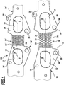
- the Fig. 1 shows at the bottom part of a sheet metal gasket layer 10, which can be a gasket layer of a multi-layer flat gasket or the only layer of a single-layer gasket, namely in the case of the embodiment shown a so-called manifold gasket, in particular an exhaust manifold gasket for installation between a cylinder head and an exhaust manifold of a multi-cylinder internal combustion engine.
- a sheet metal gasket layer 10 can be a gasket layer of a multi-layer flat gasket or the only layer of a single-layer gasket, namely in the case of the embodiment shown a so-called manifold gasket, in particular an exhaust manifold gasket for installation between a cylinder head and an exhaust manifold of a multi-cylinder internal combustion engine.
- the gasket layer 10 has a plurality of gas passage openings, of which the Fig. 1 shows only the two gas passage openings 12 and 14, but also some holes, for example several screw holes 16 for the passage of assembly screws, with the help of which the flat gasket is clamped between components, in the present case between a cylinder head and an exhaust manifold.
- the in Fig. 1 The part of the one-piece sealing layer 10 shown below comprises two first layer areas 18 with the gas passage openings 12, 14 as well as a second layer area 20, which is arranged between these first layer areas and connects the latter with one another, which is designed in the manner of an expanded metal and has sheet metal webs 22 which run obliquely to one another and which also run obliquely to a line 24, which connects the centers of the gas passage openings 12 and 14 with one another and in the illustrated embodiment of the sealing layer according to the invention runs in their longitudinal direction.
- the second layer area 20 has a multiplicity of cutouts 26, since the layer area 20 is intended to be a zone of the sealing layer 10 which has no sealing function.
- the gasket layer 10 is only in Fig. 1 Gas sealing devices indicated by dash-dotted lines are provided, in particular with sealing beads embossed into the sheet metal layer, which surround the gas passage openings 12, 14 in each case in a closed manner.
- the one in the lower part of the Fig. 1 Ready-to-install gasket layer 10 shown has a final outer contour 30, which differs from the preliminary outer contour 30 'in the upper part of the Fig. 1 shown blank 32, from which the sealing layer 10 is made, differs, namely in the Fig. 1
- the illustrated embodiments of the finished gasket layer 10 and of the blank 32 essentially only in that the outer contour 30 of the gasket layer 10 in the direction of the line 24 is larger than the outer contour 30 ′ of the blank 32.
- the upper part of the Fig. 1 shows only a part of the blank 32 stamped out of a metal sheet, this part of the blank being the one in the lower part of FIG Fig. 1
- the part shown corresponds to the finished gasket layer 10, which is why the upper part of the Fig. 1
- the same reference numerals have been used as in the lower part of FIG Fig.
- the finished gasket layer 10 and the blank 32 with regard to the size and shape of the gas passage openings 12, 14 and the screw holes 16 as well as the positions of the gas passage openings and screw holes relative to one another and to the outer contour 30 or the outer contour 30 '.
- a large number of punch cuts 26' were produced, which preferably have the shape of straight lines and in particular extend perpendicular to the line 24, but also at a small acute angle with the perpendicular to the line 24 could form.
- the punch cuts 26 ' are arranged in a plurality of groups oriented perpendicular to the line 24, the punch cuts of each group being offset in the longitudinal direction of the punch cuts with respect to the punch cuts of an adjacent group.
- the latter is subjected to tensile stress in the direction of the line 24, namely a tensile stress of such a size that is just sufficient to widen the openings formed by the punched cuts 26 'so that the recesses 26 of the finished gasket layer 10 result - the forces generating this tensile stress were in the upper part of the Fig. 1 indicated by the two arrows F; for introducing this tensile stress into the sheet metal layer forming the blank 32, the in Fig.
- the metal of the sheet metal forming the blank 32 is permanently, i.e. plastically deformed, at least essentially only at the ends of the sheet metal webs 22.
- the second layer area 20 'of the blank 32 is stretched in the direction of the line 24 by such a tensile stress and transferred into the second layer area 20 of the gasket layer 10, sheet metal webs 22 can result which are twisted about their longitudinal axes and therefore from the Gasket layer 10 protrude from the defined layer plane; then it can be expedient to press flat the stretched layer area so that a flat second layer area 20 of the finished gasket layer 10 results.
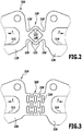
- FIGS. 2 and 3 each show a part of a second and a third embodiment of a flat gasket layer 110 and 210 according to the invention, each of which, apart from its second layer region 120 and 220, is designed similarly to that in the lower part of FIG Fig. 1 Flat gasket layer shown 10.
- the first layer areas were designated with 118 or 218 and the gas passage openings with 112 and 114 or 212 and 214.
- the second layer region 120 has sheet metal webs 122 and recesses 126, 126 'and has a diamond shape with a central opening in the form of recess 126.
- flat gasket layer 110 used blank has a second layer area lying between the two first layer areas 118, which has punch cuts which, when this second layer area is stretched in the direction of the two, into the Fig. 2
- the arrows F shown in the drawing lead to the recesses 126 and 126 '.
- the second layer area 220 has elongated recesses 226 and 226 ', which have approximately the shape of a flat oval or part of a flat oval and are obtained by stretching a blank in the direction of arrows F, which in its second layer area has punched-out cuts 26 'of the in Fig. 1 has shown blank 32.
- the Fig. 4 shows part of a blank 332 for the production of a flat gasket layer according to the invention;
- the illustrated part of this blank has a media passage opening 312 in a first layer area 318 and a screw hole 316 in a further first layer area 318 'and between these two first layer areas 318, 318' has a second layer area 320 which has been provided with punched cuts 326 '.
- the blank 332 is subjected to tensile stress, generated by tensile forces corresponding to the two in the Fig. 4 arrows F drawn in, so that cutouts similar to cutouts 26 in FIG Fig. 1 gasket layer 10 shown arise.
- the Fig. 5 shows a small outer edge area of a blank 432, which has a first layer area 418 and, in its shown outer edge area, a second layer area 420 designed as a projection, which is provided with punch cuts 426 '.
- the outer edge region of the blank 432 shown is subjected to a tensile stress corresponding to the two in FIG Fig. 5 is subject to the arrows F shown, that is to say the second layer region 420 designed as a projection is shown in FIG Fig. 5 stretched upwards, the punch cuts 426 'become recesses similar to those in FIG Fig. 1 shown recesses 26 expanded and the second layer region 420 designed as a projection according to FIG Fig. 5 extended upwards.
- the Figures 4 and 5 show that the blank 332 or 432 can be punched out of a piece of sheet metal which is smaller than a piece of sheet metal required for punching out the finished flat gasket layer, because the first layer area 318 'of the blank 332 and the second layer area 420 of the blank 432 protrudes less far beyond the adjacent blank areas than is the case in the finished flat gasket layer.
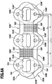
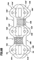
- the Fig. 6 shows two blanks according to the invention for two flat gasket layers according to the invention which are arranged at least essentially congruently one above the other in the finished flat gasket, while in FIG Fig. 6 an upper blank 532A for one gasket layer and a lower blank 532B for the other gasket layer are shown displaced somewhat relative to one another.
- the upper blank 532A has three first layer areas 518A, 518A 'and 518A "which are connected to one another via second layer areas 520A' and 520A". Each of the first layer areas 518A, 518A 'and 518A "has a gas passage opening 512A or 512A' or 512A" and screw holes 516, respectively.
- the second layer area 520A "of the blank 532A that is not to be stretched has a greater length (in FIG Figure 6A measured in the horizontal direction) than the stretchable second layer region 520A ', which is stretched by such an amount during the production of the ready-to-install gasket layer from the blank 532A (again in FIG Figure 6A horizontal direction) that the second layer area of the finished gasket layer formed from the layer area 520A 'has the same length as the second layer area 520A "of the blank 532A.
- the other blank 532B and its second layer areas 520B" and 520B' has a greater length (in FIG Figure 6A measured in the horizontal direction) than the stretchable second layer region 520A ', which is stretched by such an amount during the production of the ready-to-install gasket layer from the blank 532A (again in FIG Figure 6A horizontal direction) that the second layer area of the finished gasket layer formed from the layer area 520A 'has the same length as the second layer area 520A "of the blank
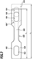
- FIG. 7 Yet another embodiment of the invention, namely with continuous lines a blank 632 according to the invention for a flat gasket layer 610 according to the invention, which, insofar as it does not match the blank 632 in its contours, has been shown with dashed lines.
- the blank 632 has two first layer areas 618 each with a gas passage opening 612 or 614 and a second layer area 620 'which connects these two first layer areas and which is tapered compared to the first layer areas 618, namely in the illustrated preferred embodiment in that the second Layer area 620 'has a smaller average width than the first layer area 618, so that the second layer area 620' in FIG Fig. 7 horizontal direction can stretch with relatively low forces.
- a constriction 620 ′′ results, that is, a reduction in the mean width of this layer area and at the same time an increase in its length, so that the flat gasket layer 610 obtained by stretching has a length L 2 which is greater than the length L 1 of the blank 632.
- the stretching of the blank 632 is carried out in such a way that the contours of the first layer regions 618 remain at least essentially unchanged.
- media passage openings and other openings and holes of a flat gasket layer according to the invention are only produced after the blank has been stretched, i.e. in particular punched out, and the same applies, for example, to the embossing of in particular media passage openings Sealing beads in the sheet metal layer.
- the contours of the flat gasket layer are reworked, in particular by a further punching process.
Landscapes
- Engineering & Computer Science (AREA)
- General Engineering & Computer Science (AREA)
- Mechanical Engineering (AREA)
- Chemical & Material Sciences (AREA)
- Combustion & Propulsion (AREA)
- Gasket Seals (AREA)
Claims (16)
- Garniture d'étanchéité plate avec au moins une couche d'étanchéité en tôle métallique en une seule pièce définissant un plan de couche, laquelle couche d'étanchéité en tôle métallique présente au moins une première région de couche dotée d'au moins une ouverture de passage d'un milieu, ainsi que, dans une vue de dessus sur la couche de tôle, au moins une deuxième région de couche à l'extérieur de la première région de couche et, dans le cas d'une garniture d'étanchéité à l'état monté, un contour extérieur prédéfini, dans laquelle la garniture d'étanchéité plate présente un dispositif d'étanchéification de milieu attribué à cette dernière pour l'ouverture de passage d'un milieu,
caractérisée en ce qu'au moins une région partielle de la deuxième région de couche de la garniture d'étanchéité plate à l'état monté se situant, dans une vue de dessus sur la couche d'étanchéité, à l'extérieur du dispositif d'étanchéification de milieu est formée par une région de la couche de tôle étirée pour obtenir le contour extérieur prédéfini dans le plan de couche et formée au moins localement de zones plastiquement déformées de la tôle métallique. - Garniture d'étanchéité plate selon la revendication 1, caractérisée en ce que la région partielle étirée présente, dans une vue de dessus sur la couche d'étanchéité, au moins un évidement entre des barrettes de tôle se déroulant de façon oblique les unes aux autres.
- Garniture d'étanchéité plate selon la revendication 2, caractérisée en ce que la couche de tôle présente plusieurs premières régions de couche et au moins deux premières régions de couche avoisinantes les unes aux autres sont reliées ensemble par au moins une deuxième région de couche, dont les barrettes de tôle se déroulent de façon oblique à la direction d'une ligne droite, laquelle relie ensemble les premières régions de couche.
- Garniture d'étanchéité plate selon la revendication 2, caractérisée en ce que, dans une vue de dessus sur la couche de tôle, la deuxième région de couche forme une saillie faisant saillie vers l'extérieur et les barrettes de tôle forment un angle avec la direction dans laquelle la saillie dépasse essentiellement par-dessus le reste de la couche de tôle.
- Garniture d'étanchéité plate selon l'une des revendications 2 à 4, caractérisée en ce que la région partielle est formée par une région en métal déployé de la couche de tôle.
- Ébauche d'une couche en tôle métallique en une seule pièce d'une garniture d'étanchéité plate dont la couche en tôle métallique présente un contour extérieur prédéfini dans le cas d'une garniture d'étanchéité à l'état monté, dans laquelle l'ébauche présente au moins une première région de couche dotée d'au moins une ouverture de passage d'un milieu, ainsi que, dans une vue de dessus sur l'ébauche, au moins une deuxième région de couche et un contour extérieur provisoire à l'extérieur de la première région de couche, caractérisée en ce que le contour extérieur provisoire est plus petit que le contour extérieur prédéfini dans une direction menant de la première à la deuxième région de couche et la couche de tôle est constituée d'un matériau métallique pouvant être déformé dans le plan de couche et est conçue dans au moins une région partielle de la deuxième région de couche de telle sorte que cette région partielle puisse être étirée par un effort de traction dans le plan de couche et dans ladite direction et ce faisant le contour extérieur provisoire de l'ébauche puisse être agrandi dans ladite direction jusqu'à obtenir le contour extérieur prédéfini.
- Ébauche selon la revendication 6, caractérisée en ce que la région partielle de la deuxième région de couche présente plusieurs percées, lesquelles, dans une vue de dessus sur la couche de tôle, sont conçues, orientées et agencées de telle sorte que les percées puissent être élargies par un effort de traction de l'ébauche dans le plan de couche et dans une direction menant de la première à la deuxième région de couche et ce faisant le contour extérieur provisoire de l'ébauche puisse être agrandi de façon prédéfinissable dans la direction de l'effort de traction.
- Ébauche selon la revendication 7, caractérisée en ce qu'au moins plusieurs des percées sont formées de découpes d'estampage en forme de lignes.
- Ébauche selon la revendication 7 ou 8, caractérisée en ce qu'au moins une des percées est formée par un évidement s'étendant à travers la couche de tôle.
- Ébauche selon l'une des revendications 7 à 9, caractérisée en ce que les percées sont conçues de façon allongée et se déroulent essentiellement transversalement à la direction de l'agrandissement prédéfini du contour extérieur de l'ébauche.
- Ébauche selon la revendication 10, caractérisée par plusieurs groupes de percées allongées, dans laquelle chaque groupe présente plusieurs percées agencées les unes derrières les autres dans la direction longitudinale des percées et les percées de chaque groupe par rapport aux percées d'un groupe avoisinant sont décalées dans la direction longitudinale des percées.
- Ébauche selon l'une des revendications 7 à 11, caractérisée par plusieurs premières régions de couche dont au moins deux premières régions de couche avoisinantes les unes aux autres sont reliées ensemble par au moins une deuxième région de couche, dont les percées sont conçues de façon allongée et se déroulent transversalement à une ligne droite, laquelle relie ensemble les premières régions de couche avoisinantes les unes aux autres.
- Ébauche selon l'une des revendications 7 à 11, caractérisée en ce que, dans une vue de dessus sur l'ébauche, la deuxième région de couche forme une saillie faisant saillie vers l'extérieur et les percées conçues de façon allongée se déroulent transversalement à la direction dans laquelle la saillie dépasse essentiellement par-dessus le reste de l'ébauche.
- Procédé de fabrication d'une couche de garniture d'étanchéité plate en tôle métallique en une seule pièce, laquelle présente, dans le cas d'une garniture d'étanchéité à l'état monté, un contour extérieur définitif prédéfini, au moins une première région de couche dotée d'au moins une ouverture de passage d'un milieu, ainsi que, dans une vue de dessus sur la couche d'étanchéité, au moins une deuxième région de couche à l'extérieur de la première région de couche, et définit un plan de couche, caractérisé en ce que dans une tôle métallique est découpée une ébauche de couche d'étanchéité avec un contour extérieur provisoire, lequel est plus petit que le contour extérieur définitif de la couche de garniture d'étanchéité plate dans au moins une première direction se situant dans le plan de couche, et en ce qu'au moins une région partielle de la deuxième région de couche est étirée par un effort de traction de l'ébauche se produisant dans la première direction de telle sorte que ce faisant le contour extérieur provisoire soit transformé au moins essentiellement en le contour extérieur définitif.
- Procédé selon la revendication 14, caractérisé en ce que dans la région partielle de la deuxième région de couche sont produites plusieurs percées, lesquelles, dans une vue de dessus sur l'ébauche, sont conçues, orientées et agencées de telle sorte que les percées puissent être élargies dans la première direction par l'effort de traction de l'ébauche, et en ce que la région partielle est étirée par l'effort de traction et moyennant quoi est déformée de telle sorte que ce faisant les percées soient élargies dans la première direction et le contour extérieur provisoire soit transformé au moins essentiellement en le contour extérieur définitif.
- Procédé selon la revendication 15, caractérisé en ce que la région partielle étirée est comprimée à plat.
Applications Claiming Priority (2)
| Application Number | Priority Date | Filing Date | Title |
|---|---|---|---|
| DE102013100612.4A DE102013100612A1 (de) | 2013-01-22 | 2013-01-22 | Metallblech-Flachdichtungslage sowie Verfahren zu ihrer Herstellung |
| PCT/EP2014/050362 WO2014114504A1 (fr) | 2013-01-22 | 2014-01-10 | Couche d'étanchéité de joint plat en tôle métallique et son procédé de fabrication |
Publications (2)
| Publication Number | Publication Date |
|---|---|
| EP2948656A1 EP2948656A1 (fr) | 2015-12-02 |
| EP2948656B1 true EP2948656B1 (fr) | 2021-03-03 |
Family
ID=49955367
Family Applications (1)
| Application Number | Title | Priority Date | Filing Date |
|---|---|---|---|
| EP14700292.7A Active EP2948656B1 (fr) | 2013-01-22 | 2014-01-10 | Couche d'étanchéité de joint plat en tôle métallique et son procédé de fabrication |
Country Status (5)
| Country | Link |
|---|---|
| US (1) | US9664285B2 (fr) |
| EP (1) | EP2948656B1 (fr) |
| CN (1) | CN104937231B (fr) |
| DE (1) | DE102013100612A1 (fr) |
| WO (1) | WO2014114504A1 (fr) |
Families Citing this family (2)
| Publication number | Priority date | Publication date | Assignee | Title |
|---|---|---|---|---|
| DE102015103721B3 (de) * | 2015-03-13 | 2015-12-17 | Benteler Automobiltechnik Gmbh | Verfahren zur Herstellung eines Blechumformbauteils mit bereichsweise voneinander verschiedenen Wandstärken sowie Achshilfsrahmen |
| US10738889B2 (en) * | 2018-04-18 | 2020-08-11 | Ishikawa Gasket Co., Ltd. | Gasket |
Family Cites Families (12)
| Publication number | Priority date | Publication date | Assignee | Title |
|---|---|---|---|---|
| US1839336A (en) * | 1926-12-31 | 1932-01-05 | Victor Mfg & Gasket Co | Adjustable gasket |
| US1913736A (en) * | 1932-02-08 | 1933-06-13 | Victor Mfg & Gasket Co | Gasket |
| JPS6172852A (ja) * | 1984-09-17 | 1986-04-14 | Nissan Motor Co Ltd | 排気マニホルド用ガスケツト |
| JPH0622135Y2 (ja) | 1986-01-13 | 1994-06-08 | 石川ガスケット株式会社 | 金属積叢形マニホ−ルドガスケット |
| DE4241759C1 (de) | 1992-12-11 | 1994-02-17 | Freudenberg Carl Fa | Dichtung zur gasdichten Befestigung eines Ansaugkrümmers am Zylinderkopf einer Verbrennungskraftmaschine |
| JP3363781B2 (ja) * | 1998-03-18 | 2003-01-08 | 石川ガスケット株式会社 | 複数のシール部を有する金属板ガスケット |
| DE10103885A1 (de) * | 2001-01-30 | 2002-08-08 | Elringklinger Ag | Flachdichtung für den Ansaug- oder Abgaskrümmerbereich eines mehrzylindrigen Verbrennungsmotors |
| JP2004360801A (ja) * | 2003-06-05 | 2004-12-24 | Yanmar Co Ltd | マニホールドガスケット |
| FR2886364A1 (fr) * | 2005-05-24 | 2006-12-01 | Renault Sas | Joint plat metallique a parties de liaison souples |
| US8128099B2 (en) * | 2005-11-14 | 2012-03-06 | Dana Automotive Systems Group, Llc | Gasket |
| DE102007053929B4 (de) * | 2006-12-09 | 2013-09-12 | Tenneco Gmbh | Sammelflansch |
| DE202006018649U1 (de) * | 2006-12-09 | 2007-03-08 | Heinrich Gillet Gmbh | Sammelflansch |
-
2013
- 2013-01-22 DE DE102013100612.4A patent/DE102013100612A1/de not_active Withdrawn
-
2014
- 2014-01-10 EP EP14700292.7A patent/EP2948656B1/fr active Active
- 2014-01-10 CN CN201480005684.2A patent/CN104937231B/zh active Active
- 2014-01-10 WO PCT/EP2014/050362 patent/WO2014114504A1/fr not_active Ceased
-
2015
- 2015-07-21 US US14/804,602 patent/US9664285B2/en active Active
Non-Patent Citations (1)
| Title |
|---|
| None * |
Also Published As
| Publication number | Publication date |
|---|---|
| US9664285B2 (en) | 2017-05-30 |
| US20150323075A1 (en) | 2015-11-12 |
| CN104937231B (zh) | 2018-06-22 |
| EP2948656A1 (fr) | 2015-12-02 |
| WO2014114504A1 (fr) | 2014-07-31 |
| DE102013100612A1 (de) | 2014-07-24 |
| CN104937231A (zh) | 2015-09-23 |
Similar Documents
| Publication | Publication Date | Title |
|---|---|---|
| DE69215460T2 (de) | Metalldichtung sowie Herstellungsverfahren dazu | |
| DE69104937T2 (de) | Metalldichtung für Sammelleitung. | |
| DE102007022103A1 (de) | Selbstbrechende Seitenplatten für einen Kühler | |
| DE19751293A1 (de) | Einschichtige oder mehrschichtige Metallzylinderkopfdichtung und Verfahren zu ihrer Herstellung | |
| DE112006003987B4 (de) | Verbindungsstruktur aus Metallplatten | |
| DE102009022392A1 (de) | Verfahren zur Herstellung von metallischen Dichtungselementen | |
| EP1389701A2 (fr) | Joint plat à couches multiples et méthode pour joindre les couches d'un tel joint | |
| EP0292754B1 (fr) | Bride pour attacher des tuyaux | |
| EP2948656B1 (fr) | Couche d'étanchéité de joint plat en tôle métallique et son procédé de fabrication | |
| DE102016002582A1 (de) | Flachdichtung, insbesondere Zylinderkopfdichtung | |
| DE102012107539A1 (de) | Metallische Flachdichtung und Verfahren zu ihrer Herstellung | |
| EP2989355B1 (fr) | Joint plat | |
| EP2989356B1 (fr) | Joint d'étanchéité plat métallique ainsi que procédé de fabrication dudit joint d'étanchéité | |
| EP1628050B1 (fr) | Joint plat métallique avec feuille d'étanchéité réduite | |
| DE112019003842T5 (de) | Selbstformende dichtungsanordnung und verfahren zu deren konstruktion und zusammenbau | |
| EP0967421B1 (fr) | Joint plat | |
| DE102006015002B4 (de) | Wärmetauscher und Verfahren zur Herstellung desselben | |
| DE602005000474T2 (de) | Zylinderkopfdichtung | |
| DE102013205468B4 (de) | Verfahren zur Herstellung eines Anlageabschnittes zur Befestigung eines weiteren Bauteils an einem Zylinderrohr für einen Schwingungsdämpfer | |
| DE10123485B4 (de) | Flachdichtung sowie Verfahren zu ihrer Herstellung | |
| DE102007025927B4 (de) | Flachdichtung | |
| DE10314693B4 (de) | Flachdichtung | |
| EP3225889B1 (fr) | Éclissage pour liaison de couches de tôles et de joint de culasse | |
| DE102013221784A1 (de) | Zylinderkopfdichtung | |
| EP1271018B1 (fr) | Joint d'étanchéité plat |
Legal Events
| Date | Code | Title | Description |
|---|---|---|---|
| PUAI | Public reference made under article 153(3) epc to a published international application that has entered the european phase |
Free format text: ORIGINAL CODE: 0009012 |
|
| 17P | Request for examination filed |
Effective date: 20150717 |
|
| AK | Designated contracting states |
Kind code of ref document: A1 Designated state(s): AL AT BE BG CH CY CZ DE DK EE ES FI FR GB GR HR HU IE IS IT LI LT LU LV MC MK MT NL NO PL PT RO RS SE SI SK SM TR |
|
| AX | Request for extension of the european patent |
Extension state: BA ME |
|
| DAX | Request for extension of the european patent (deleted) | ||
| REG | Reference to a national code |
Ref country code: DE Ref legal event code: R079 Ref document number: 502014015326 Country of ref document: DE Free format text: PREVIOUS MAIN CLASS: F01N0013180000 Ipc: F16J0015020000 |
|
| STAA | Information on the status of an ep patent application or granted ep patent |
Free format text: STATUS: EXAMINATION IS IN PROGRESS |
|
| RIC1 | Information provided on ipc code assigned before grant |
Ipc: F16J 15/06 20060101ALI20180611BHEP Ipc: F16J 15/02 20060101AFI20180611BHEP Ipc: F16J 15/08 20060101ALI20180611BHEP Ipc: F01N 13/18 20100101ALI20180611BHEP Ipc: B21D 35/00 20060101ALI20180611BHEP |
|
| 17Q | First examination report despatched |
Effective date: 20180710 |
|
| GRAP | Despatch of communication of intention to grant a patent |
Free format text: ORIGINAL CODE: EPIDOSNIGR1 |
|
| STAA | Information on the status of an ep patent application or granted ep patent |
Free format text: STATUS: GRANT OF PATENT IS INTENDED |
|
| INTG | Intention to grant announced |
Effective date: 20200814 |
|
| GRAS | Grant fee paid |
Free format text: ORIGINAL CODE: EPIDOSNIGR3 |
|
| GRAA | (expected) grant |
Free format text: ORIGINAL CODE: 0009210 |
|
| STAA | Information on the status of an ep patent application or granted ep patent |
Free format text: STATUS: THE PATENT HAS BEEN GRANTED |
|
| AK | Designated contracting states |
Kind code of ref document: B1 Designated state(s): AL AT BE BG CH CY CZ DE DK EE ES FI FR GB GR HR HU IE IS IT LI LT LU LV MC MK MT NL NO PL PT RO RS SE SI SK SM TR |
|
| REG | Reference to a national code |
Ref country code: GB Ref legal event code: FG4D Free format text: NOT ENGLISH |
|
| REG | Reference to a national code |
Ref country code: AT Ref legal event code: REF Ref document number: 1367573 Country of ref document: AT Kind code of ref document: T Effective date: 20210315 Ref country code: CH Ref legal event code: EP |
|
| REG | Reference to a national code |
Ref country code: DE Ref legal event code: R096 Ref document number: 502014015326 Country of ref document: DE |
|
| REG | Reference to a national code |
Ref country code: IE Ref legal event code: FG4D Free format text: LANGUAGE OF EP DOCUMENT: GERMAN |
|
| REG | Reference to a national code |
Ref country code: LT Ref legal event code: MG9D |
|
| PG25 | Lapsed in a contracting state [announced via postgrant information from national office to epo] |
Ref country code: NO Free format text: LAPSE BECAUSE OF FAILURE TO SUBMIT A TRANSLATION OF THE DESCRIPTION OR TO PAY THE FEE WITHIN THE PRESCRIBED TIME-LIMIT Effective date: 20210603 Ref country code: BG Free format text: LAPSE BECAUSE OF FAILURE TO SUBMIT A TRANSLATION OF THE DESCRIPTION OR TO PAY THE FEE WITHIN THE PRESCRIBED TIME-LIMIT Effective date: 20210603 Ref country code: FI Free format text: LAPSE BECAUSE OF FAILURE TO SUBMIT A TRANSLATION OF THE DESCRIPTION OR TO PAY THE FEE WITHIN THE PRESCRIBED TIME-LIMIT Effective date: 20210303 Ref country code: GR Free format text: LAPSE BECAUSE OF FAILURE TO SUBMIT A TRANSLATION OF THE DESCRIPTION OR TO PAY THE FEE WITHIN THE PRESCRIBED TIME-LIMIT Effective date: 20210604 Ref country code: HR Free format text: LAPSE BECAUSE OF FAILURE TO SUBMIT A TRANSLATION OF THE DESCRIPTION OR TO PAY THE FEE WITHIN THE PRESCRIBED TIME-LIMIT Effective date: 20210303 Ref country code: LT Free format text: LAPSE BECAUSE OF FAILURE TO SUBMIT A TRANSLATION OF THE DESCRIPTION OR TO PAY THE FEE WITHIN THE PRESCRIBED TIME-LIMIT Effective date: 20210303 |
|
| REG | Reference to a national code |
Ref country code: NL Ref legal event code: MP Effective date: 20210303 |
|
| PG25 | Lapsed in a contracting state [announced via postgrant information from national office to epo] |
Ref country code: SE Free format text: LAPSE BECAUSE OF FAILURE TO SUBMIT A TRANSLATION OF THE DESCRIPTION OR TO PAY THE FEE WITHIN THE PRESCRIBED TIME-LIMIT Effective date: 20210303 Ref country code: PL Free format text: LAPSE BECAUSE OF FAILURE TO SUBMIT A TRANSLATION OF THE DESCRIPTION OR TO PAY THE FEE WITHIN THE PRESCRIBED TIME-LIMIT Effective date: 20210303 Ref country code: LV Free format text: LAPSE BECAUSE OF FAILURE TO SUBMIT A TRANSLATION OF THE DESCRIPTION OR TO PAY THE FEE WITHIN THE PRESCRIBED TIME-LIMIT Effective date: 20210303 Ref country code: RS Free format text: LAPSE BECAUSE OF FAILURE TO SUBMIT A TRANSLATION OF THE DESCRIPTION OR TO PAY THE FEE WITHIN THE PRESCRIBED TIME-LIMIT Effective date: 20210303 |
|
| PG25 | Lapsed in a contracting state [announced via postgrant information from national office to epo] |
Ref country code: NL Free format text: LAPSE BECAUSE OF FAILURE TO SUBMIT A TRANSLATION OF THE DESCRIPTION OR TO PAY THE FEE WITHIN THE PRESCRIBED TIME-LIMIT Effective date: 20210303 |
|
| PG25 | Lapsed in a contracting state [announced via postgrant information from national office to epo] |
Ref country code: SM Free format text: LAPSE BECAUSE OF FAILURE TO SUBMIT A TRANSLATION OF THE DESCRIPTION OR TO PAY THE FEE WITHIN THE PRESCRIBED TIME-LIMIT Effective date: 20210303 Ref country code: EE Free format text: LAPSE BECAUSE OF FAILURE TO SUBMIT A TRANSLATION OF THE DESCRIPTION OR TO PAY THE FEE WITHIN THE PRESCRIBED TIME-LIMIT Effective date: 20210303 Ref country code: CZ Free format text: LAPSE BECAUSE OF FAILURE TO SUBMIT A TRANSLATION OF THE DESCRIPTION OR TO PAY THE FEE WITHIN THE PRESCRIBED TIME-LIMIT Effective date: 20210303 |
|
| PG25 | Lapsed in a contracting state [announced via postgrant information from national office to epo] |
Ref country code: SK Free format text: LAPSE BECAUSE OF FAILURE TO SUBMIT A TRANSLATION OF THE DESCRIPTION OR TO PAY THE FEE WITHIN THE PRESCRIBED TIME-LIMIT Effective date: 20210303 Ref country code: RO Free format text: LAPSE BECAUSE OF FAILURE TO SUBMIT A TRANSLATION OF THE DESCRIPTION OR TO PAY THE FEE WITHIN THE PRESCRIBED TIME-LIMIT Effective date: 20210303 Ref country code: PT Free format text: LAPSE BECAUSE OF FAILURE TO SUBMIT A TRANSLATION OF THE DESCRIPTION OR TO PAY THE FEE WITHIN THE PRESCRIBED TIME-LIMIT Effective date: 20210705 Ref country code: ES Free format text: LAPSE BECAUSE OF FAILURE TO SUBMIT A TRANSLATION OF THE DESCRIPTION OR TO PAY THE FEE WITHIN THE PRESCRIBED TIME-LIMIT Effective date: 20210303 Ref country code: IS Free format text: LAPSE BECAUSE OF FAILURE TO SUBMIT A TRANSLATION OF THE DESCRIPTION OR TO PAY THE FEE WITHIN THE PRESCRIBED TIME-LIMIT Effective date: 20210703 |
|
| REG | Reference to a national code |
Ref country code: DE Ref legal event code: R097 Ref document number: 502014015326 Country of ref document: DE |
|
| PLBE | No opposition filed within time limit |
Free format text: ORIGINAL CODE: 0009261 |
|
| STAA | Information on the status of an ep patent application or granted ep patent |
Free format text: STATUS: NO OPPOSITION FILED WITHIN TIME LIMIT |
|
| PG25 | Lapsed in a contracting state [announced via postgrant information from national office to epo] |
Ref country code: AL Free format text: LAPSE BECAUSE OF FAILURE TO SUBMIT A TRANSLATION OF THE DESCRIPTION OR TO PAY THE FEE WITHIN THE PRESCRIBED TIME-LIMIT Effective date: 20210303 Ref country code: DK Free format text: LAPSE BECAUSE OF FAILURE TO SUBMIT A TRANSLATION OF THE DESCRIPTION OR TO PAY THE FEE WITHIN THE PRESCRIBED TIME-LIMIT Effective date: 20210303 |
|
| 26N | No opposition filed |
Effective date: 20211206 |
|
| PG25 | Lapsed in a contracting state [announced via postgrant information from national office to epo] |
Ref country code: SI Free format text: LAPSE BECAUSE OF FAILURE TO SUBMIT A TRANSLATION OF THE DESCRIPTION OR TO PAY THE FEE WITHIN THE PRESCRIBED TIME-LIMIT Effective date: 20210303 |
|
| PG25 | Lapsed in a contracting state [announced via postgrant information from national office to epo] |
Ref country code: IT Free format text: LAPSE BECAUSE OF FAILURE TO SUBMIT A TRANSLATION OF THE DESCRIPTION OR TO PAY THE FEE WITHIN THE PRESCRIBED TIME-LIMIT Effective date: 20210303 |
|
| PG25 | Lapsed in a contracting state [announced via postgrant information from national office to epo] |
Ref country code: IS Free format text: LAPSE BECAUSE OF FAILURE TO SUBMIT A TRANSLATION OF THE DESCRIPTION OR TO PAY THE FEE WITHIN THE PRESCRIBED TIME-LIMIT Effective date: 20210703 |
|
| PG25 | Lapsed in a contracting state [announced via postgrant information from national office to epo] |
Ref country code: MC Free format text: LAPSE BECAUSE OF FAILURE TO SUBMIT A TRANSLATION OF THE DESCRIPTION OR TO PAY THE FEE WITHIN THE PRESCRIBED TIME-LIMIT Effective date: 20210303 |
|
| REG | Reference to a national code |
Ref country code: CH Ref legal event code: PL |
|
| GBPC | Gb: european patent ceased through non-payment of renewal fee |
Effective date: 20220110 |
|
| REG | Reference to a national code |
Ref country code: BE Ref legal event code: MM Effective date: 20220131 |
|
| PG25 | Lapsed in a contracting state [announced via postgrant information from national office to epo] |
Ref country code: LU Free format text: LAPSE BECAUSE OF NON-PAYMENT OF DUE FEES Effective date: 20220110 Ref country code: GB Free format text: LAPSE BECAUSE OF NON-PAYMENT OF DUE FEES Effective date: 20220110 |
|
| PG25 | Lapsed in a contracting state [announced via postgrant information from national office to epo] |
Ref country code: FR Free format text: LAPSE BECAUSE OF NON-PAYMENT OF DUE FEES Effective date: 20220131 Ref country code: BE Free format text: LAPSE BECAUSE OF NON-PAYMENT OF DUE FEES Effective date: 20220131 |
|
| PG25 | Lapsed in a contracting state [announced via postgrant information from national office to epo] |
Ref country code: LI Free format text: LAPSE BECAUSE OF NON-PAYMENT OF DUE FEES Effective date: 20220131 Ref country code: CH Free format text: LAPSE BECAUSE OF NON-PAYMENT OF DUE FEES Effective date: 20220131 |
|
| PG25 | Lapsed in a contracting state [announced via postgrant information from national office to epo] |
Ref country code: IE Free format text: LAPSE BECAUSE OF NON-PAYMENT OF DUE FEES Effective date: 20220110 |
|
| REG | Reference to a national code |
Ref country code: AT Ref legal event code: MM01 Ref document number: 1367573 Country of ref document: AT Kind code of ref document: T Effective date: 20220110 |
|
| PG25 | Lapsed in a contracting state [announced via postgrant information from national office to epo] |
Ref country code: AT Free format text: LAPSE BECAUSE OF NON-PAYMENT OF DUE FEES Effective date: 20220110 |
|
| P01 | Opt-out of the competence of the unified patent court (upc) registered |
Effective date: 20230512 |
|
| PG25 | Lapsed in a contracting state [announced via postgrant information from national office to epo] |
Ref country code: HU Free format text: LAPSE BECAUSE OF FAILURE TO SUBMIT A TRANSLATION OF THE DESCRIPTION OR TO PAY THE FEE WITHIN THE PRESCRIBED TIME-LIMIT; INVALID AB INITIO Effective date: 20140110 |
|
| PG25 | Lapsed in a contracting state [announced via postgrant information from national office to epo] |
Ref country code: MK Free format text: LAPSE BECAUSE OF FAILURE TO SUBMIT A TRANSLATION OF THE DESCRIPTION OR TO PAY THE FEE WITHIN THE PRESCRIBED TIME-LIMIT Effective date: 20210303 Ref country code: CY Free format text: LAPSE BECAUSE OF FAILURE TO SUBMIT A TRANSLATION OF THE DESCRIPTION OR TO PAY THE FEE WITHIN THE PRESCRIBED TIME-LIMIT Effective date: 20210303 |
|
| PG25 | Lapsed in a contracting state [announced via postgrant information from national office to epo] |
Ref country code: MT Free format text: LAPSE BECAUSE OF FAILURE TO SUBMIT A TRANSLATION OF THE DESCRIPTION OR TO PAY THE FEE WITHIN THE PRESCRIBED TIME-LIMIT Effective date: 20210303 |
|
| PG25 | Lapsed in a contracting state [announced via postgrant information from national office to epo] |
Ref country code: TR Free format text: LAPSE BECAUSE OF FAILURE TO SUBMIT A TRANSLATION OF THE DESCRIPTION OR TO PAY THE FEE WITHIN THE PRESCRIBED TIME-LIMIT Effective date: 20210303 |
|
| PGFP | Annual fee paid to national office [announced via postgrant information from national office to epo] |
Ref country code: DE Payment date: 20260120 Year of fee payment: 13 |