EP2948733B1 - Verfahren und vorrichtung zur fahrzeugvermessung - Google Patents
Verfahren und vorrichtung zur fahrzeugvermessung Download PDFInfo
- Publication number
- EP2948733B1 EP2948733B1 EP13807960.3A EP13807960A EP2948733B1 EP 2948733 B1 EP2948733 B1 EP 2948733B1 EP 13807960 A EP13807960 A EP 13807960A EP 2948733 B1 EP2948733 B1 EP 2948733B1
- Authority
- EP
- European Patent Office
- Prior art keywords
- vehicle
- measurement
- mathematical model
- tyres
- tyre
- Prior art date
- Legal status (The legal status is an assumption and is not a legal conclusion. Google has not performed a legal analysis and makes no representation as to the accuracy of the status listed.)
- Not-in-force
Links
Images
Classifications
-
- G—PHYSICS
- G01—MEASURING; TESTING
- G01M—TESTING STATIC OR DYNAMIC BALANCE OF MACHINES OR STRUCTURES; TESTING OF STRUCTURES OR APPARATUS, NOT OTHERWISE PROVIDED FOR
- G01M17/00—Testing of vehicles
- G01M17/007—Wheeled or endless-tracked vehicles
-
- G—PHYSICS
- G01—MEASURING; TESTING
- G01B—MEASURING LENGTH, THICKNESS OR SIMILAR LINEAR DIMENSIONS; MEASURING ANGLES; MEASURING AREAS; MEASURING IRREGULARITIES OF SURFACES OR CONTOURS
- G01B11/00—Measuring arrangements characterised by the use of optical techniques
- G01B11/16—Measuring arrangements characterised by the use of optical techniques for measuring the deformation in a solid, e.g. optical strain gauge
- G01B11/168—Measuring arrangements characterised by the use of optical techniques for measuring the deformation in a solid, e.g. optical strain gauge by means of polarisation
-
- G—PHYSICS
- G06—COMPUTING OR CALCULATING; COUNTING
- G06T—IMAGE DATA PROCESSING OR GENERATION, IN GENERAL
- G06T7/00—Image analysis
- G06T7/0002—Inspection of images, e.g. flaw detection
- G06T7/0004—Industrial image inspection
- G06T7/001—Industrial image inspection using an image reference approach
-
- G—PHYSICS
- G06—COMPUTING OR CALCULATING; COUNTING
- G06T—IMAGE DATA PROCESSING OR GENERATION, IN GENERAL
- G06T7/00—Image analysis
- G06T7/70—Determining position or orientation of objects or cameras
- G06T7/73—Determining position or orientation of objects or cameras using feature-based methods
- G06T7/75—Determining position or orientation of objects or cameras using feature-based methods involving models
-
- G—PHYSICS
- G01—MEASURING; TESTING
- G01B—MEASURING LENGTH, THICKNESS OR SIMILAR LINEAR DIMENSIONS; MEASURING ANGLES; MEASURING AREAS; MEASURING IRREGULARITIES OF SURFACES OR CONTOURS
- G01B2210/00—Aspects not specifically covered by any group under G01B, e.g. of wheel alignment, caliper-like sensors
- G01B2210/10—Wheel alignment
- G01B2210/28—Beam projector and related sensors, camera, inclinometer or other active sensing or projecting device
- G01B2210/283—Beam projectors and related sensors
- G01B2210/286—Projecting a light pattern on the wheel or vehicle body
-
- G—PHYSICS
- G06—COMPUTING OR CALCULATING; COUNTING
- G06T—IMAGE DATA PROCESSING OR GENERATION, IN GENERAL
- G06T2207/00—Indexing scheme for image analysis or image enhancement
- G06T2207/10—Image acquisition modality
- G06T2207/10004—Still image; Photographic image
- G06T2207/10012—Stereo images
-
- G—PHYSICS
- G06—COMPUTING OR CALCULATING; COUNTING
- G06T—IMAGE DATA PROCESSING OR GENERATION, IN GENERAL
- G06T2207/00—Indexing scheme for image analysis or image enhancement
- G06T2207/30—Subject of image; Context of image processing
- G06T2207/30108—Industrial image inspection
-
- G—PHYSICS
- G06—COMPUTING OR CALCULATING; COUNTING
- G06T—IMAGE DATA PROCESSING OR GENERATION, IN GENERAL
- G06T2207/00—Indexing scheme for image analysis or image enhancement
- G06T2207/30—Subject of image; Context of image processing
- G06T2207/30248—Vehicle exterior or interior
- G06T2207/30252—Vehicle exterior; Vicinity of vehicle
Definitions
- the invention relates to a method and a device for checking the correct positioning of a vehicle on a measuring station for vehicle measurement.
- the flatness of the measuring station and an exactly horizontal orientation of the vehicle play a major role in achieving precise results during the survey.
- the manufacturers state that the maximum height difference between the wheel contact surfaces must not exceed 1 mm.
- a method for checking the correct positioning of a vehicle on a measuring station for vehicle measurement comprises the steps of recording images of at least two tires of the vehicle; identifying features in the captured images describing at least a portion of the respective captured tire; approximating a mathematical model to the identified features of the tire; determining the extent of flattening of each tire from the approximated mathematical model; and comparing the flattening of the at least two tires.
- the identified features describe in particular that region of the tire in which a flattening occurs, in particular a region arranged around the footprint of the tire.
- An inventive device for checking the correct positioning of a vehicle on a measuring station for vehicle measurement, in particular for checking a correct horizontal orientation of the vehicle, with at least two transducers, which are each adapted to receive images of a tire of the vehicle, has an evaluation device which is formed To identify features in the captured images describing at least a portion of the respective captured tire; to approximate a mathematical model to the identified features; determine the degree of flattening of each tire from the approximated mathematical model; and compare the flattening of at least two tires.
- a device according to the invention according to claim 7 and a method according to claim 1 according to the invention the proper horizontal alignment of the motor vehicle to be measured can be checked easily and conveniently and in particular automatically.
- a check according to the invention can be set up by updating the software of an existing measuring device without having to install additional hardware.
- the check according to the invention can therefore be implemented inexpensively both in new and in existing measuring stations.
- the evaluation device can be integrated into one of the transducers used for vehicle measurement.
- the device may have four or more transducers to capture all wheels of the vehicle at the same time.
- the method may additionally include the step of issuing a warning and / or blocking a planned vehicle measurement when the difference in the flattening of the tires exceeds a predetermined limit.
- Each tire or at least a portion of the tire can each be illuminated by a projector, which can be configured as a light or laser projector, in order to enable a structured image recording of the tire or of a partial area.
- a projector which can be configured as a light or laser projector, in order to enable a structured image recording of the tire or of a partial area.
- the pictures of the tires can be taken with a stereo camera as stereo images, in order to account for three-dimensional information.
- the mathematical model that is adapted to the recorded images may in particular be a two- or three-dimensional mathematical model, for example a rotationally symmetric polynomial model or a spline model.
- Such models have proven to be particularly well suited to produce a sufficiently accurate mathematical model of the tire with reasonable computational effort.
- the method may additionally include taking multiple images of each wheel as the vehicle passes by; to determine from the mathematical model rotation centers of wheels; and to check if the wheels have moved in one plane while passing by.
- the sensor is equipped with a gravity sensor that allows the sensor to be aligned in the gravity field of the sensor
- the orientation of the plane of the measuring station in the gravitational field of the earth can also be determined.
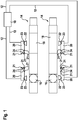
- FIG. 1 shows a schematic plan view of a measuring station for vehicle measurement.
- the measuring station has two mutually parallel rails 14, which may be, for example, the rails 14 of a lift.
- the rails 14 can also be installed firmly on the ground of the measuring station. Alternatively, the method can also be carried out without rails 14 on the floor of the measuring station.
- each of the two running rails 14 is equipped with a turning plate 16 which makes it possible to deflect the steerable wheels of a vehicle arranged on the running rails 14 when the vehicle is arranged on the running rails 14 such that its steerable wheels rest on the turning plates 16 are supported.
- the rails 14 each have a sliding plate 18.
- the sliding plates 18 are displaceable parallel to the longitudinal extent of the rails 14 and can thus be arranged at a variable distance from the associated rotary plate 16. In this way, the measuring station can be adapted to different vehicles having different distances between the front wheels and the rear wheels.
- transducers 20 are arranged in a rectangular arrangement.
- Two (front) transducers 20 are arranged at the height of the rotary plates 16 and thus adjacent to the usually steerable front wheels of a parked on the rails 14 vehicle.
- Two (rear) transducers 20 can be moved along the rails 14, so that their position can be adjusted to the center distance of the vehicle to be measured such that the rear transducers 20 are always positioned opposite the rear wheels of the vehicle parked on the rails 14.
- Each of the transducers 20 includes an image pickup device (image sensor) 22 for detecting a measured value, which is e.g. is designed as a (stereo) camera, and an integrated lighting device 23, which is designed to illuminate the wheel to be measured opposite the respective sensor 20.
- image sensor image sensor 22 for detecting a measured value
- integrated lighting device 23 which is designed to illuminate the wheel to be measured opposite the respective sensor 20.
- Each of the transducers 20 can also have position lights 21 and in each case one optical sensor 24 in order to be able to determine the position of the respective transducers 20 with respect to at least two other transducers 20.
- the transducers 20 are connected via data lines 12 to a central evaluation device 10. Alternatively, the transducers 20 can be wirelessly connected to the central evaluation device 10.
- the evaluation device 10 may also be arranged in one or more of the transducers 20.
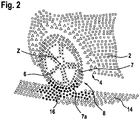
- FIG. 2 shows an example of a 3D point cloud, as recorded by a transducer 20, which is arranged on the left front wheel 8 of a vehicle.
- the affiliation of the recorded points to the wheel 8, to the body 2, for example the wheel arch 4, and to the roadway 14, 16 is determined. From the points associated with the tire 7 of the wheel 8, those points 7a belonging to the lower portion of the tire 7 flattened due to the self-weight of the vehicle are identified.
- a mathematical model in particular a so-called spline model, is adapted to the points which represent the tire 7 and in particular to the points 7 a of the lower, flattened region of the tire 7. From the parameters of the mathematical model, the flattening of the tire 7 can then be determined.
- This process is performed for at least two tires 7 of the vehicle, and the flattenings of the tires 7 are compared with each other. If the differences in the extent of the flattening between different tires 7 of a vehicle exceed a predefined limit value, a warning signal is output and / or a planned vehicle measurement is prevented since the vehicle measurement could no longer be performed with the required accuracy when the limit value is exceeded, but leads to incorrect results would lead.
- one or more images are taken of each wheel 8 as the vehicle travels onto or over the measuring station. From the at least one recorded image, in addition, the center of rotation Z of each wheel 8 can be determined.
- a suitable method is for example in DE 10 2006 048 725 A1 described.
- the invention thus makes it possible to conveniently and reliably check the conditions for a successful vehicle measurement, in particular a horizontal alignment of the vehicle body.
Landscapes
- Physics & Mathematics (AREA)
- General Physics & Mathematics (AREA)
- Engineering & Computer Science (AREA)
- Computer Vision & Pattern Recognition (AREA)
- Theoretical Computer Science (AREA)
- Quality & Reliability (AREA)
- Length Measuring Devices By Optical Means (AREA)
Description
- Die Erfindung betrifft ein Verfahren und eine Vorrichtung zum Überprüfen der korrekten Positionierung eines Fahrzeugs auf einem Messplatz zur Fahrzeugvermessung.
- Bei der Fahrzeugvermessung spielen die Ebenheit des Messplatzes und eine exakt horizontale Ausrichtung des Fahrzeugs eine große Rolle, um bei der Vermessung genaue Ergebnisse erzielen zu können. So geben die Hersteller beispielsweise vor, dass die maximale Höhendifferenz zwischen den Radaufstandsflächen nicht mehr als 1 mm betragen darf.
- Zudem sind gleiche Luftdrücke, zumindest in den Rädern einer Achse, erforderlich, um eine Schiefstellung der Karosserie aufgrund einer unterschiedlichen Komprimierung der Reifen zu vermeiden.
- Um zuverlässig richtige Messergebnisse zu erhalten, ist es daher erforderlich, sowohl die Ebenheit und die horizontale Ausrichtung des Messplatzes als auch den Luftdruck in den Rädern des zu vermessenden Fahrzeugs vor jeder Messung zu überprüfen.
- Diese Überprüfung ist zeitaufwendig, so dass die Gefahr besteht, dass aus Bequemlichkeit auf die notwendigen Kontrollen verzichtet und die Fahrzeugvermessung in der Folge fehlerhaft durchgeführt wird.
- Aus der
WO 01/23834 A1 - Es ist daher eine Aufgabe der Erfindung, die Durchführung der notwendigen Kontrollen zu vereinfachen und weitestgehend zu automatisieren.
- Ein erfindungsgemäßes Verfahren zum Überprüfen der korrekten Positionierung eines Fahrzeugs auf einem Messplatz zur Fahrzeugvermessung, insbesondere zum Überprüfen einer korrekten horizontalen Ausrichtung des Fahrzeugs, umfasst die Schritte des Aufnehmens von Bildern von wenigstens zwei Reifen des Fahrzeugs; des Identifizierens von Merkmalen in den aufgenommenen Bildern, die wenigstens einen Bereich des jeweils aufgenommenen Reifens beschreiben; des Approximierens eines mathematischen Models an die identifizierten Merkmale des Reifens; des Bestimmens des Ausmaßes der Abplattung jedes Reifens aus dem approximierten mathematischen Modell; und des Vergleichens der Abplattung der wenigstens zwei Reifen.
- Die identifizierten Merkmale beschreiben dabei insbesondere denjenigen Bereich des Reifens, in dem eine Abplattung auftritt, insbesondere also einen um die Aufstandsfläche des Reifens angeordneten Bereich.
- Eine erfindungsgemäße Vorrichtung zum Überprüfen der korrekten Positionierung eines Fahrzeugs auf einem Messplatz zur Fahrzeugvermessung, insbesondere zum Überprüfen einer korrekten horizontalen Ausrichtung des Fahrzeugs, mit wenigstens zwei Messwertaufnehmern, die jeweils ausgebildet sind, Bilder eines Reifens des Fahrzeugs aufzunehmen, hat eine Auswertvorrichtung, die ausgebildet ist, Merkmale in den aufgenommenen Bildern zu identifizieren, die wenigstens einen Bereich des jeweils aufgenommenen Reifens beschreiben; ein mathematisches Modell an die identifizierten Merkmale zu approximieren; das Ausmaß der Abplattung jedes Reifens aus dem approximierten mathematischen Modell zu bestimmen; und die Abplattung von wenigstens zwei Reifen miteinander zu vergleichen.
- Mit einer erfindungsgemäßen Vorrichtung gemäß Anspruch 7 und einem erfindungsgemäßen Verfahren gemäß Anspruch 1 kann die ordnungsgemäße horizontale Ausrichtung des zu vermessenden Kraftfahrzeugs einfach und bequem und insbesondere automatisiert überprüft werden. Insbesondere kann eine erfindungsgemäße Überprüfung durch ein Software-Update einer vorhandenen Vermessungsvorrichtung eingerichtet werden, ohne dass zusätzliche Hardware installiert werden muss. Die erfindungsgemäße Überprüfung kann daher kostengünstig sowohl in neuen als auch in bereits bestehenden Messplätzen implementiert werden.
- Insbesondere kann die Auswertvorrichtung in einen der Messwertaufnehmer, die zur Fahrzeugvermessung verwendet werden, integriert sein.
- Die Vorrichtung kann vier oder mehr Messwertaufnehmer aufweisen, um alle Räder des Fahrzeugs gleichzeitig erfassen zu können.
- Das Verfahren kann zusätzlich den Schritt aufweisen, eine Warnung auszugeben und/oder eine geplante Fahrzeugvermessung zu blockieren, wenn die Differenz in der Abplattung der Reifen einen vorgegebenen Grenzwert überschreitet.
- Jeder Reifen bzw. wenigstens ein Teilbereich des Reifens kann jeweils von einem Projektor, der als Licht- oder Laserprojektor ausgebildet sein kann, beleuchtet werden, um eine strukturierte Bildaufnahme des Reifens bzw. eines Teilbereiches zu ermöglichen.
- Die Bilder der Reifen können mit einer Stereokamera als Stereo-Bilder aufgenommen werden, um auch dreidimensionale Informationen berücksichtigen zu können.
- Das mathematische Modell, das an die aufgenommenen Bilder angepasst wird, kann insbesondere ein zwei- oder dreidimensionales mathematisches Modell, beispielsweise ein rotationssymmetrisches Polynom-Modell oder ein Spline-Modell sein. Derartige Modelle haben sich als besonders gut geeignet erwiesen, um mit vertretbarem Rechenaufwand ein hinreichend genaues mathematisches Modell der Reifen zu erzeugen.
- Das Verfahren kann zusätzlich umfassen, während einer Vorbeifahrt des Fahrzeugs mehrere Bilder jedes Rades aufzunehmen; aus dem mathematischen Modell die Drehzentren der Räder zu bestimmen; und zu überprüfen, ob sich die Räder während der Vorbeifahrt in einer Ebene bewegt haben.
- Auf diese Weise können Schiefstände des Fahrzeugs, die sich aus unterschiedlichen Luftdrücken in den Reifen ergeben, auch Unebenheiten des Messplatzes zuverlässig erkannt werden, so dass eine manuelle Überprüfung des Messplatzes nicht mehr erforderlich ist.
- Falls der Messwertaufnehmer mit einer Schwerkraftsensor ausgestattet ist, der es ermöglicht, die Ausrichtung des Messwertaufnehmers im Schwerkraftfeld der Erde zu bestimmen, kann zusätzlich auch die Ausrichtung der Ebene des Messplatzes im Schwerkraftfeld der Erde bestimmt werden.
- Die Erfindung wird im Folgenden anhand der beigefügten Figuren näher erläutert. Dabei zeigt:
-
Figur 1 eine schematische Draufsicht auf einen Messplatz zur Fahrzeugvermessung; -
Figur 2 ein Beispiel für eine 3D-Punktwolke, die von einem Messwertaufnehmer aufgenommen worden ist, der neben einem linken Vorderrad eines Kraftfahrzeugs angeordnet ist; -
Figur 1 zeigt eine schematische Draufsicht auf einen Messplatz zur Fahrzeugvermessung. - Der Messplatz weist zwei parallel zueinander angeordnete Fahrschienen 14 auf, die beispielsweise die Fahrschienen 14 einer Hebebühne sein können. Die Fahrschienen 14 können aber auch fest am Boden des Messplatzes installiert sein. Alternativ kann das Verfahren auch ohne Fahrschienen 14 auf dem Boden des Messplatzes durchgeführt werden.
- In einem in der
Figur 1 links dargestellten Bereich ist jede der beiden Fahrschienen 14 mit einer Drehplatte 16 ausgestattet, die es ermöglicht, die lenkbaren Räder eines auf den Fahrschienen 14 angeordneten Fahrzeugs einzulenken, wenn das Fahrzeug so auf den Fahrschienen 14 angeordnet ist, dass seine lenkbaren Räder auf den Drehplatten 16 abgestützt sind. - In einem in der
Figur 1 auf der rechten Seite dargestellten Bereich weisen die Fahrschienen 14 jeweils eine Schiebeplatte 18 auf. Die Schiebeplatten 18 sind parallel zur Längserstreckung der Fahrschienen 14 verschiebbar und können so in einem variablen Abstand von der zugehörigen Drehplatte 16 angeordnet werden. Auf diese Weise kann der Messplatz an verschiedene Fahrzeuge, die unterschiedliche Abstände zwischen den Vorderrädern und den Hinterrädern haben, angepasst werden. - Um die Fahrschienen 14 sind in einer rechteckigen Anordnung vier Messwertaufnehmer 20 angeordnet. Zwei (vordere) Messwertaufnehmer 20 sind auf Höhe der Drehplatten 16 und damit neben den üblicherweise lenkbaren Vorderrädern eines auf den Fahrschienen 14 abgestellten Fahrzeugs angeordnet. Zwei (hintere) Messwertaufnehmer 20 können entlang der Fahrschienen 14 bewegt werden, so dass ihre Position derart an den Achsabstand des zu vermessenden Fahrzeugs angepasst werden kann, dass die hinteren Messwertaufnehmer 20 stets den Hinterrädern des auf den Fahrschienen 14 abgestellten Fahrzeugs gegenüberliegend positioniert sind.
- Jeder der Messwertaufnehmer 20 weist eine Bildaufnahmevorrichtung (Bildsensor) 22 zur Messwerterfassung, die z.B. als (Stereo-)Kamera ausgebildet ist, und eine integrierte Beleuchtungsvorrichtung 23 auf, die ausgebildet ist, um das dem jeweiligen Messwertaufnehmer 20 gegenüberliegende zu vermessende Rad zu beleuchten.
- Jeder der Messwertaufnehmer 20 kann auch Positionslichter 21 und jeweils einen optischen Sensor 24 aufweisen, um die Position des jeweiligen Messwertaufnehmers 20 in Bezug auf wenigstens zwei andere der Messwertaufnehmer 20 bestimmen zu können.
- Die Messwertaufnehmer 20 sind über Datenleitungen 12 mit einer zentralen Auswertvorrichtung 10 verbunden. Alternativ können die Messwertaufnehmer 20 drahtlos mit der zentralen Auswertvorrichtung 10 verbunden sein. Die Auswertvorrichtung 10 kann auch in einem oder mehreren der Messwertaufnehmer 20 angeordnet sein.
-
Figur 2 zeigt ein Beispiel für eine 3D-Punktwolke, wie sie von einem Messwertaufnehmer 20 aufgenommen wird, der am linken vorderen Rad 8 eines Fahrzeugs angeordnet ist. - Durch die Kombination intelligenter Bildverarbeitungsalgorithmen wird die Zugehörigkeit der aufgenommenen Punkte zum Rad 8, zur Karosserie 2, z.B. dem Radkasten 4, und zur Fahrbahn 14, 16 bestimmt. Aus den Punkten, die dem Reifen 7 des Rades 8 zugeordnet sind, werden diejenigen Punkte 7a identifiziert, die zum unteren Bereich des Reifens 7 gehören, der aufgrund des Eigengewichtes des Fahrzeugs abgeplattet ist.
- Ein mathematisches Modell, insbesondere ein sogenanntes Spline-Modell, wird an die Punkte, die den Reifen 7 repräsentieren und insbesondere an die Punkte 7a des unteren, abgeplatteten Bereichs des Reifens 7 angepasst. Aus den Parametern des mathematischen Modells kann dann die Abplattung des Reifens 7 bestimmt werden.
- Dieser Vorgang wird für mindestens zwei Reifen 7 des Fahrzeugs durchgeführt, und die Abplattungen der Reifen 7 werden miteinander verglichen. Überschreiten die Unterschiede des Ausmaßes der Abplattungen zwischen verschiedenen Reifen 7 eines Fahrzeugs einen vorgegebenen Grenzwert, wird ein Warnsignal ausgegeben und/oder eine geplante Fahrzeugvermessung verhindert, da die Fahrzeugvermessung bei Überschreiten des Grenzwertes nicht mehr mit der notwendigen Genauigkeit durchgeführt werden könnte, sondern zu falschen Ergebnissen führen würde.
- In einer erweiterten Ausführungsform werden von jedem Rad 8 eines oder mehrere Bilder aufgenommen, während das Fahrzeug auf bzw. über den Messplatz fährt. Aus dem wenigstens einen aufgenommenen Bild kann zusätzlich das Drehzentrum Z jedes Rades 8 bestimmt werden. Ein hierfür geeignetes Verfahren wird beispielsweise in
DE 10 2006 048 725 A1 beschrieben. - Im Folgenden kann festgestellt werden, ob sich die Drehzentren Z der Räder 8 während des Auffahrens auf den Messplatz in einer Ebene bewegen, d.h. ob die Ebene des Messplatzes wirklich eben ist. Auch hier wird eine Warnung ausgegeben und/oder die Messung abgebrochen, wenn die Unebenheit des Messplatzes eine vorgegebene Grenze überschreitet, so dass eine fehlerfreie Messung nicht mehr möglich ist.
- Die Erfindung ermöglicht es somit, die Voraussetzungen für eine erfolgreiche Fahrzeugvermessung, insbesondere eine horizontale Ausrichtung der Fahrzeugkarosserie, bequem und zuverlässig zu überprüfen.
Claims (10)
- Verfahren zum Überprüfen der korrekten Positionierung eines Fahrzeugs auf einem Messplatz zur Fahrzeugvermessung, dadurch gekennzeichnet, dass das Verfahren die Schritte umfasst:a) Aufnehmen von Bildern von wenigstens zwei Reifen (7) des Fahrzeugs;b) Identifizieren von Merkmalen in den aufgenommenen Bildern, die wenigstens einen Bereich des jeweils aufgenommenen Reifens (7) beschreiben;c) Approximieren eines mathematischen Modells an die identifizierten Merkmale;d) Bestimmen des Ausmaßes der Abplattung jedes Reifens (7) aus dem approximierten mathematischen Modell;e) Vergleichen des Ausmaßes der Abplattung der wenigstens zwei Reifen (7).
- Verfahren nach Anspruch 1, das zusätzlich den Schritt aufweist, eine Warnung auszugeben und/oder eine geplante Fahrzeugvermessung zu blockieren, wenn die Differenz in der Abplattung der Reifen (7) einen vorgegebenen Grenzwert überschreitet.
- Verfahren nach Anspruch 1 oder 2, wobei die Reifen (7) jeweils von einem Projektor (23) beleuchtet werden.
- Verfahren nach einem der vorangehenden Ansprüche, wobei mit einer Stereo-Kamera (22) Stereo-Bilder der Reifen (7) aufgenommen werden.
- Verfahren nach einem der vorangehenden Ansprüche, wobei das mathematische Modell ein zwei- oder dreidimensionales mathematisches Modell ist.
- Verfahren nach einem der vorangehenden Ansprüche, wobei das Verfahren einschließt,- während einer Vorbeifahrt des Fahrzeugs wenigstens ein Bild jedes Reifen (8) des Fahrzeugs aufzunehmen;- aus dem mathematischen Modell die Drehzentren (Z) der Räder (8) zu bestimmen; und- zu überprüfen, ob sich die Drehzentren (Z) der Räder (8) während der Vorbeifahrt in einer Ebene bewegt haben.
- Vorrichtung zum Überprüfen der korrekten Positionierung eines Fahrzeugs auf einem Messplatz zur Fahrzeugvermessung, mit wenigstens zwei Messwertaufnehmern (20), die jeweils ausgebildet sind, Bilder eines Reifens (7) des Fahrzeugs aufzunehmen,
dadurch gekennzeichnet, dass die Vorrichtung eine Auswertvorrichtung (10) aufweist, die ausgebildet ist,- Merkmale in den aufgenommenen Bildern zu identifizieren, die wenigstens einen Bereich des jeweils aufgenommenen Reifens (7) beschreiben;- ein mathematisches Modell an die identifizierten Merkmale zu approximieren;- das Ausmaß der Abplattung jedes Reifens (7) aus dem approximierten mathematischen Modell zu bestimmen; und- das Ausmaß der Abplattung von wenigstens zwei Reifen (7) miteinander zu vergleichen. - Vorrichtung nach Anspruch 6, wobei die Auswertvorrichtung (10) in wenigstens einen der Messwertaufnehmer (20) integriert ist.
- Vorrichtung nach Anspruch 7 oder 8, wobei die Vorrichtung vier Messwertaufnehmer (20) aufweist.
- Vorrichtung zur Fahrzeugvermessung, die eine Vorrichtung zum Überprüfen der korrekten Positionierung eines Fahrzeugs nach einem der Ansprüche 7 bis 9 umfasst.
Applications Claiming Priority (2)
| Application Number | Priority Date | Filing Date | Title |
|---|---|---|---|
| DE102013200910.0A DE102013200910A1 (de) | 2013-01-22 | 2013-01-22 | Verfahren und Vorrichtung zur Fahrzeugvermessung |
| PCT/EP2013/075897 WO2014114402A1 (de) | 2013-01-22 | 2013-12-09 | Verfahren und vorrichtung zur fahrzeugvermessung |
Publications (2)
| Publication Number | Publication Date |
|---|---|
| EP2948733A1 EP2948733A1 (de) | 2015-12-02 |
| EP2948733B1 true EP2948733B1 (de) | 2018-10-31 |
Family
ID=49779869
Family Applications (1)
| Application Number | Title | Priority Date | Filing Date |
|---|---|---|---|
| EP13807960.3A Not-in-force EP2948733B1 (de) | 2013-01-22 | 2013-12-09 | Verfahren und vorrichtung zur fahrzeugvermessung |
Country Status (5)
| Country | Link |
|---|---|
| US (1) | US9599538B2 (de) |
| EP (1) | EP2948733B1 (de) |
| CN (1) | CN104937366A (de) |
| DE (1) | DE102013200910A1 (de) |
| WO (1) | WO2014114402A1 (de) |
Families Citing this family (7)
| Publication number | Priority date | Publication date | Assignee | Title |
|---|---|---|---|---|
| DE102014204809A1 (de) * | 2014-03-14 | 2015-09-17 | Robert Bosch Gmbh | Verfahren und Vorrichtung zum Überprüfen der Radaufhängung eines Fahrzeugs |
| CN105388028B (zh) * | 2015-11-24 | 2018-09-28 | 上海斐讯数据通信技术有限公司 | 移动终端及其检测汽车轮胎下沉量的方法和装置 |
| BR102017002219B1 (pt) * | 2017-02-02 | 2020-01-07 | Vale S/A | Sistema e método para o monitoramento de rodas ferroviárias |
| WO2018158995A1 (ja) * | 2017-02-28 | 2018-09-07 | パナソニックIpマネジメント株式会社 | 軸重計測装置および軸重計測方法 |
| US10671873B2 (en) * | 2017-03-10 | 2020-06-02 | Tusimple, Inc. | System and method for vehicle wheel detection |
| WO2019087444A1 (ja) * | 2017-10-31 | 2019-05-09 | パナソニックIpマネジメント株式会社 | ダブルタイヤ判定装置、及びダブルタイヤ判定方法 |
| CN116878402B (zh) * | 2023-07-11 | 2024-07-19 | 北京博科测试系统股份有限公司 | 非接触轮眉测量传感器及方法 |
Family Cites Families (11)
| Publication number | Priority date | Publication date | Assignee | Title |
|---|---|---|---|---|
| FR2602048A1 (fr) * | 1985-12-30 | 1988-01-29 | Clerc Alain | Dispositif pour evaluer la deformation des pneumatiques de vehicules |
| US5962779A (en) * | 1997-01-29 | 1999-10-05 | Shell Oil Company | Method for determining tire inflation status |
| US6237234B1 (en) * | 1999-09-28 | 2001-05-29 | Snap-On Technologies, Inc. | Method and apparatus for measuring vehicle wheel roll radius |
| US7336350B2 (en) * | 2002-05-15 | 2008-02-26 | Hunter Engineering Company | Wheel alignment apparatus and method utilizing three-dimensional imaging |
| US7702126B2 (en) * | 2004-12-15 | 2010-04-20 | Hunter Engineering Company | Vehicle lift measurement system |
| DE102005017624A1 (de) * | 2005-04-15 | 2006-10-19 | Robert Bosch Gmbh | Verfahren zum Bestimmen der Rad- und/oder Achsgeometrie von Kraftfahrzeugen |
| DE102006035924A1 (de) * | 2006-07-31 | 2008-02-07 | Robert Bosch Gmbh | Verfahren zum Bestimmen der Drehachse und des Drehzentrums eines Fahrzeugrads |
| DE102006048725A1 (de) * | 2006-10-16 | 2008-04-17 | Robert Bosch Gmbh | Verfahren zum Ermitteln der Drehachse eines Fahrzeugrades |
| WO2010028965A1 (de) * | 2008-09-12 | 2010-03-18 | Robert Bosch Gmbh | Targetanordnung, satz von target-anordnungen und vorrichtung zur optischen achsvermessung |
| JP5387202B2 (ja) * | 2009-07-23 | 2014-01-15 | 横浜ゴム株式会社 | タイヤ解析システムおよびタイヤ解析方法 |
| CN104160258A (zh) * | 2011-11-03 | 2014-11-19 | 尼恩麦提克斯有限公司 | 用于估计车辆轮胎的气压状态的系统和方法 |
-
2013
- 2013-01-22 DE DE102013200910.0A patent/DE102013200910A1/de not_active Withdrawn
- 2013-12-09 EP EP13807960.3A patent/EP2948733B1/de not_active Not-in-force
- 2013-12-09 WO PCT/EP2013/075897 patent/WO2014114402A1/de not_active Ceased
- 2013-12-09 CN CN201380071040.9A patent/CN104937366A/zh active Pending
- 2013-12-09 US US14/762,625 patent/US9599538B2/en not_active Expired - Fee Related
Non-Patent Citations (1)
| Title |
|---|
| None * |
Also Published As
| Publication number | Publication date |
|---|---|
| US9599538B2 (en) | 2017-03-21 |
| EP2948733A1 (de) | 2015-12-02 |
| DE102013200910A1 (de) | 2014-07-24 |
| US20150369701A1 (en) | 2015-12-24 |
| CN104937366A (zh) | 2015-09-23 |
| WO2014114402A1 (de) | 2014-07-31 |
Similar Documents
| Publication | Publication Date | Title |
|---|---|---|
| EP2948733B1 (de) | Verfahren und vorrichtung zur fahrzeugvermessung | |
| EP2539117B1 (de) | Verfahren und vorrichtung zum bestimmen von abständen an einem fahrzeug | |
| DE102012215754A1 (de) | Verfahren und Vorrichtung zur Fahrzeugvermessung | |
| EP1042643B1 (de) | Vorrichtung zum bestimmen der rad- und/oder achsgeometrie von kraftfahrzeugen | |
| EP1042644B1 (de) | Vorrichtung zum bestimmen der rad- und/oder achsgeometrie von kraftfahrzeugen | |
| EP2948748A1 (de) | Vorrichtung und verfahren zum überwachen und kalibrieren einer vorrichtung zur messung der profiltiefe eines reifens | |
| EP3612794B1 (de) | Verfahren und vorrichtung zur fahrwerksvermessung | |
| DE102008045307A1 (de) | Vorrichtung und Verfahren zum Bestimmen und Einstellen der Fahrwerksgeometrie eines Fahrzeuges | |
| DE102012202271A1 (de) | Vorrichtung und Verfahren zur Reifenprüfung | |
| DE102012224260A1 (de) | Vorrichtung und Verfahren zur Messung der Profiltiefe eines Reifens | |
| DE102006048725A1 (de) | Verfahren zum Ermitteln der Drehachse eines Fahrzeugrades | |
| EP2049870A1 (de) | Verfahren zum bestimmen der drehachse und des drehzentrums eines fahrzeugrads | |
| WO2020038675A1 (de) | Messvorrichtung, vorrichtung, system, fahrzeug und verfahren | |
| WO2013079395A1 (de) | Verfahren zur positionierung eines messsystems und messsystem zur durchführung des verfahrens | |
| DE102013222291A1 (de) | Verfahren und Vorrichtung zur Schätzung der Einbauwinkel eines in einem Fahrzeug montierten bildgebenden Sensors | |
| DE102019003238B4 (de) | Fahrzeugortung durch Kartenabgleich unter Berücksichtigung eines Straßenprofils | |
| DE102015223500B4 (de) | Verfahren und Vorrichtung zur Prüfung der Funktionalität einer außenseitigen Lichteinrichtung eines Fahrzeugs | |
| EP2960883B1 (de) | Bestimmung mindestens eines Merkmals eines Fahrzeugs | |
| WO2020052877A1 (de) | Verfahren und vorrichtung zum ausrichten einer kalibriereinrichtung | |
| DE102016225154A1 (de) | Vorrichtung zur Bestimmung einer Eigenschaft eines Rades eines Fahrzeugs an dem Fahrzeug | |
| WO2015197668A1 (de) | Verfahren und vorrichtung zur überprüfung des beladungsgewichtes eines lkw | |
| DE102013021475A1 (de) | Optische Lenkwinkelbestimmung | |
| DE19949982C2 (de) | Verfahren und Einrichtung zum Überprüfen von Radaufhängungskomponenten | |
| EP3688409B1 (de) | Verfahren zur bestimmung eines radsturzes oder einer spur | |
| DE102008046104A1 (de) | Vorrichtung und Verfahren zur Spurvermessung von Fahrzeugen |
Legal Events
| Date | Code | Title | Description |
|---|---|---|---|
| PUAI | Public reference made under article 153(3) epc to a published international application that has entered the european phase |
Free format text: ORIGINAL CODE: 0009012 |
|
| 17P | Request for examination filed |
Effective date: 20150824 |
|
| AK | Designated contracting states |
Kind code of ref document: A1 Designated state(s): AL AT BE BG CH CY CZ DE DK EE ES FI FR GB GR HR HU IE IS IT LI LT LU LV MC MK MT NL NO PL PT RO RS SE SI SK SM TR |
|
| AX | Request for extension of the european patent |
Extension state: BA ME |
|
| DAX | Request for extension of the european patent (deleted) | ||
| GRAP | Despatch of communication of intention to grant a patent |
Free format text: ORIGINAL CODE: EPIDOSNIGR1 |
|
| INTG | Intention to grant announced |
Effective date: 20180517 |
|
| GRAS | Grant fee paid |
Free format text: ORIGINAL CODE: EPIDOSNIGR3 |
|
| GRAA | (expected) grant |
Free format text: ORIGINAL CODE: 0009210 |
|
| AK | Designated contracting states |
Kind code of ref document: B1 Designated state(s): AL AT BE BG CH CY CZ DE DK EE ES FI FR GB GR HR HU IE IS IT LI LT LU LV MC MK MT NL NO PL PT RO RS SE SI SK SM TR |
|
| REG | Reference to a national code |
Ref country code: CH Ref legal event code: EP Ref country code: GB Ref legal event code: FG4D Free format text: NOT ENGLISH |
|
| REG | Reference to a national code |
Ref country code: AT Ref legal event code: REF Ref document number: 1059917 Country of ref document: AT Kind code of ref document: T Effective date: 20181115 |
|
| REG | Reference to a national code |
Ref country code: DE Ref legal event code: R096 Ref document number: 502013011509 Country of ref document: DE |
|
| REG | Reference to a national code |
Ref country code: IE Ref legal event code: FG4D Free format text: LANGUAGE OF EP DOCUMENT: GERMAN |
|
| REG | Reference to a national code |
Ref country code: NL Ref legal event code: MP Effective date: 20181031 |
|
| REG | Reference to a national code |
Ref country code: LT Ref legal event code: MG4D |
|
| PG25 | Lapsed in a contracting state [announced via postgrant information from national office to epo] |
Ref country code: NO Free format text: LAPSE BECAUSE OF FAILURE TO SUBMIT A TRANSLATION OF THE DESCRIPTION OR TO PAY THE FEE WITHIN THE PRESCRIBED TIME-LIMIT Effective date: 20190131 Ref country code: BG Free format text: LAPSE BECAUSE OF FAILURE TO SUBMIT A TRANSLATION OF THE DESCRIPTION OR TO PAY THE FEE WITHIN THE PRESCRIBED TIME-LIMIT Effective date: 20190131 Ref country code: LT Free format text: LAPSE BECAUSE OF FAILURE TO SUBMIT A TRANSLATION OF THE DESCRIPTION OR TO PAY THE FEE WITHIN THE PRESCRIBED TIME-LIMIT Effective date: 20181031 Ref country code: FI Free format text: LAPSE BECAUSE OF FAILURE TO SUBMIT A TRANSLATION OF THE DESCRIPTION OR TO PAY THE FEE WITHIN THE PRESCRIBED TIME-LIMIT Effective date: 20181031 Ref country code: LV Free format text: LAPSE BECAUSE OF FAILURE TO SUBMIT A TRANSLATION OF THE DESCRIPTION OR TO PAY THE FEE WITHIN THE PRESCRIBED TIME-LIMIT Effective date: 20181031 Ref country code: PL Free format text: LAPSE BECAUSE OF FAILURE TO SUBMIT A TRANSLATION OF THE DESCRIPTION OR TO PAY THE FEE WITHIN THE PRESCRIBED TIME-LIMIT Effective date: 20181031 Ref country code: HR Free format text: LAPSE BECAUSE OF FAILURE TO SUBMIT A TRANSLATION OF THE DESCRIPTION OR TO PAY THE FEE WITHIN THE PRESCRIBED TIME-LIMIT Effective date: 20181031 Ref country code: ES Free format text: LAPSE BECAUSE OF FAILURE TO SUBMIT A TRANSLATION OF THE DESCRIPTION OR TO PAY THE FEE WITHIN THE PRESCRIBED TIME-LIMIT Effective date: 20181031 Ref country code: IS Free format text: LAPSE BECAUSE OF FAILURE TO SUBMIT A TRANSLATION OF THE DESCRIPTION OR TO PAY THE FEE WITHIN THE PRESCRIBED TIME-LIMIT Effective date: 20190228 |
|
| REG | Reference to a national code |
Ref country code: DE Ref legal event code: R082 Ref document number: 502013011509 Country of ref document: DE Representative=s name: SCHMITT-NILSON SCHRAUD WAIBEL WOHLFROM PATENTA, DE Ref country code: DE Ref legal event code: R081 Ref document number: 502013011509 Country of ref document: DE Owner name: BEISSBARTH GMBH, DE Free format text: FORMER OWNER: ROBERT BOSCH GMBH, 70469 STUTTGART, DE |
|
| PG25 | Lapsed in a contracting state [announced via postgrant information from national office to epo] |
Ref country code: PT Free format text: LAPSE BECAUSE OF FAILURE TO SUBMIT A TRANSLATION OF THE DESCRIPTION OR TO PAY THE FEE WITHIN THE PRESCRIBED TIME-LIMIT Effective date: 20190301 Ref country code: GR Free format text: LAPSE BECAUSE OF FAILURE TO SUBMIT A TRANSLATION OF THE DESCRIPTION OR TO PAY THE FEE WITHIN THE PRESCRIBED TIME-LIMIT Effective date: 20190201 Ref country code: NL Free format text: LAPSE BECAUSE OF FAILURE TO SUBMIT A TRANSLATION OF THE DESCRIPTION OR TO PAY THE FEE WITHIN THE PRESCRIBED TIME-LIMIT Effective date: 20181031 Ref country code: SE Free format text: LAPSE BECAUSE OF FAILURE TO SUBMIT A TRANSLATION OF THE DESCRIPTION OR TO PAY THE FEE WITHIN THE PRESCRIBED TIME-LIMIT Effective date: 20181031 Ref country code: RS Free format text: LAPSE BECAUSE OF FAILURE TO SUBMIT A TRANSLATION OF THE DESCRIPTION OR TO PAY THE FEE WITHIN THE PRESCRIBED TIME-LIMIT Effective date: 20181031 Ref country code: AL Free format text: LAPSE BECAUSE OF FAILURE TO SUBMIT A TRANSLATION OF THE DESCRIPTION OR TO PAY THE FEE WITHIN THE PRESCRIBED TIME-LIMIT Effective date: 20181031 |
|
| REG | Reference to a national code |
Ref country code: GB Ref legal event code: 732E Free format text: REGISTERED BETWEEN 20190523 AND 20190529 |
|
| RAP2 | Party data changed (patent owner data changed or rights of a patent transferred) |
Owner name: BEISSBARTH GMBH |
|
| PG25 | Lapsed in a contracting state [announced via postgrant information from national office to epo] |
Ref country code: CZ Free format text: LAPSE BECAUSE OF FAILURE TO SUBMIT A TRANSLATION OF THE DESCRIPTION OR TO PAY THE FEE WITHIN THE PRESCRIBED TIME-LIMIT Effective date: 20181031 Ref country code: DK Free format text: LAPSE BECAUSE OF FAILURE TO SUBMIT A TRANSLATION OF THE DESCRIPTION OR TO PAY THE FEE WITHIN THE PRESCRIBED TIME-LIMIT Effective date: 20181031 |
|
| REG | Reference to a national code |
Ref country code: CH Ref legal event code: PL |
|
| REG | Reference to a national code |
Ref country code: DE Ref legal event code: R097 Ref document number: 502013011509 Country of ref document: DE |
|
| PG25 | Lapsed in a contracting state [announced via postgrant information from national office to epo] |
Ref country code: MC Free format text: LAPSE BECAUSE OF FAILURE TO SUBMIT A TRANSLATION OF THE DESCRIPTION OR TO PAY THE FEE WITHIN THE PRESCRIBED TIME-LIMIT Effective date: 20181031 Ref country code: SK Free format text: LAPSE BECAUSE OF FAILURE TO SUBMIT A TRANSLATION OF THE DESCRIPTION OR TO PAY THE FEE WITHIN THE PRESCRIBED TIME-LIMIT Effective date: 20181031 Ref country code: RO Free format text: LAPSE BECAUSE OF FAILURE TO SUBMIT A TRANSLATION OF THE DESCRIPTION OR TO PAY THE FEE WITHIN THE PRESCRIBED TIME-LIMIT Effective date: 20181031 Ref country code: LU Free format text: LAPSE BECAUSE OF NON-PAYMENT OF DUE FEES Effective date: 20181209 Ref country code: EE Free format text: LAPSE BECAUSE OF FAILURE TO SUBMIT A TRANSLATION OF THE DESCRIPTION OR TO PAY THE FEE WITHIN THE PRESCRIBED TIME-LIMIT Effective date: 20181031 Ref country code: SM Free format text: LAPSE BECAUSE OF FAILURE TO SUBMIT A TRANSLATION OF THE DESCRIPTION OR TO PAY THE FEE WITHIN THE PRESCRIBED TIME-LIMIT Effective date: 20181031 |
|
| PLBE | No opposition filed within time limit |
Free format text: ORIGINAL CODE: 0009261 |
|
| STAA | Information on the status of an ep patent application or granted ep patent |
Free format text: STATUS: NO OPPOSITION FILED WITHIN TIME LIMIT |
|
| REG | Reference to a national code |
Ref country code: IE Ref legal event code: MM4A |
|
| REG | Reference to a national code |
Ref country code: BE Ref legal event code: MM Effective date: 20181231 |
|
| 26N | No opposition filed |
Effective date: 20190801 |
|
| PG25 | Lapsed in a contracting state [announced via postgrant information from national office to epo] |
Ref country code: SI Free format text: LAPSE BECAUSE OF FAILURE TO SUBMIT A TRANSLATION OF THE DESCRIPTION OR TO PAY THE FEE WITHIN THE PRESCRIBED TIME-LIMIT Effective date: 20181031 Ref country code: IE Free format text: LAPSE BECAUSE OF NON-PAYMENT OF DUE FEES Effective date: 20181209 |
|
| PG25 | Lapsed in a contracting state [announced via postgrant information from national office to epo] |
Ref country code: BE Free format text: LAPSE BECAUSE OF NON-PAYMENT OF DUE FEES Effective date: 20181231 |
|
| PG25 | Lapsed in a contracting state [announced via postgrant information from national office to epo] |
Ref country code: LI Free format text: LAPSE BECAUSE OF NON-PAYMENT OF DUE FEES Effective date: 20181231 Ref country code: CH Free format text: LAPSE BECAUSE OF NON-PAYMENT OF DUE FEES Effective date: 20181231 |
|
| PG25 | Lapsed in a contracting state [announced via postgrant information from national office to epo] |
Ref country code: MT Free format text: LAPSE BECAUSE OF FAILURE TO SUBMIT A TRANSLATION OF THE DESCRIPTION OR TO PAY THE FEE WITHIN THE PRESCRIBED TIME-LIMIT Effective date: 20181031 |
|
| REG | Reference to a national code |
Ref country code: AT Ref legal event code: MM01 Ref document number: 1059917 Country of ref document: AT Kind code of ref document: T Effective date: 20181209 |
|
| PG25 | Lapsed in a contracting state [announced via postgrant information from national office to epo] |
Ref country code: TR Free format text: LAPSE BECAUSE OF FAILURE TO SUBMIT A TRANSLATION OF THE DESCRIPTION OR TO PAY THE FEE WITHIN THE PRESCRIBED TIME-LIMIT Effective date: 20181031 |
|
| PG25 | Lapsed in a contracting state [announced via postgrant information from national office to epo] |
Ref country code: AT Free format text: LAPSE BECAUSE OF NON-PAYMENT OF DUE FEES Effective date: 20181209 |
|
| PG25 | Lapsed in a contracting state [announced via postgrant information from national office to epo] |
Ref country code: CY Free format text: LAPSE BECAUSE OF FAILURE TO SUBMIT A TRANSLATION OF THE DESCRIPTION OR TO PAY THE FEE WITHIN THE PRESCRIBED TIME-LIMIT Effective date: 20181031 Ref country code: MK Free format text: LAPSE BECAUSE OF NON-PAYMENT OF DUE FEES Effective date: 20181031 Ref country code: HU Free format text: LAPSE BECAUSE OF FAILURE TO SUBMIT A TRANSLATION OF THE DESCRIPTION OR TO PAY THE FEE WITHIN THE PRESCRIBED TIME-LIMIT; INVALID AB INITIO Effective date: 20131209 |
|
| PGFP | Annual fee paid to national office [announced via postgrant information from national office to epo] |
Ref country code: FR Payment date: 20211220 Year of fee payment: 9 Ref country code: GB Payment date: 20211222 Year of fee payment: 9 |
|
| PGFP | Annual fee paid to national office [announced via postgrant information from national office to epo] |
Ref country code: DE Payment date: 20220228 Year of fee payment: 9 |
|
| PGFP | Annual fee paid to national office [announced via postgrant information from national office to epo] |
Ref country code: IT Payment date: 20211230 Year of fee payment: 9 |
|
| REG | Reference to a national code |
Ref country code: DE Ref legal event code: R119 Ref document number: 502013011509 Country of ref document: DE |
|
| GBPC | Gb: european patent ceased through non-payment of renewal fee |
Effective date: 20221209 |
|
| PG25 | Lapsed in a contracting state [announced via postgrant information from national office to epo] |
Ref country code: GB Free format text: LAPSE BECAUSE OF NON-PAYMENT OF DUE FEES Effective date: 20221209 Ref country code: DE Free format text: LAPSE BECAUSE OF NON-PAYMENT OF DUE FEES Effective date: 20230701 |
|
| PG25 | Lapsed in a contracting state [announced via postgrant information from national office to epo] |
Ref country code: FR Free format text: LAPSE BECAUSE OF NON-PAYMENT OF DUE FEES Effective date: 20221231 |
|
| PG25 | Lapsed in a contracting state [announced via postgrant information from national office to epo] |
Ref country code: IT Free format text: LAPSE BECAUSE OF NON-PAYMENT OF DUE FEES Effective date: 20221209 |