EP2949238B1 - Ensemble support pour glissière - Google Patents
Ensemble support pour glissière Download PDFInfo
- Publication number
- EP2949238B1 EP2949238B1 EP14170151.6A EP14170151A EP2949238B1 EP 2949238 B1 EP2949238 B1 EP 2949238B1 EP 14170151 A EP14170151 A EP 14170151A EP 2949238 B1 EP2949238 B1 EP 2949238B1
- Authority
- EP
- European Patent Office
- Prior art keywords
- arm
- bracket
- elastic
- hook
- rack
- Prior art date
- Legal status (The legal status is an assumption and is not a legal conclusion. Google has not performed a legal analysis and makes no representation as to the accuracy of the status listed.)
- Active
Links
Images



Classifications
-
- H—ELECTRICITY
- H05—ELECTRIC TECHNIQUES NOT OTHERWISE PROVIDED FOR
- H05K—PRINTED CIRCUITS; CASINGS OR CONSTRUCTIONAL DETAILS OF ELECTRIC APPARATUS; MANUFACTURE OF ASSEMBLAGES OF ELECTRICAL COMPONENTS
- H05K7/00—Constructional details common to different types of electric apparatus
- H05K7/14—Mounting supporting structure in casing or on frame or rack
- H05K7/1485—Servers; Data center rooms, e.g. 19-inch computer racks
- H05K7/1488—Cabinets therefor, e.g. chassis or racks or mechanical interfaces between blades and support structures
- H05K7/1489—Cabinets therefor, e.g. chassis or racks or mechanical interfaces between blades and support structures characterized by the mounting of blades therein, e.g. brackets, rails, trays
-
- A—HUMAN NECESSITIES
- A47—FURNITURE; DOMESTIC ARTICLES OR APPLIANCES; COFFEE MILLS; SPICE MILLS; SUCTION CLEANERS IN GENERAL
- A47B—TABLES; DESKS; OFFICE FURNITURE; CABINETS; DRAWERS; GENERAL DETAILS OF FURNITURE
- A47B88/00—Drawers for tables, cabinets or like furniture; Guides for drawers
- A47B88/40—Sliding drawers; Slides or guides therefor
- A47B88/423—Fastening devices for slides or guides
- A47B88/43—Fastening devices for slides or guides at cabinet side
Definitions
- the present invention relates to a bracket assembly for a slide which can be manually operated.
- a rack device is assembled on a rack by means of a pair of slide assemblies. That is to say, the rack usually comprises a first pair of supports and a second pair of supports. Wherein, the first pair of supports corresponds in position to the second pair of supports.
- One side of the rack device is assembled on the first pair of supports by a slide assembly; the other side of the rack device is assembled on the second pair of supports by another slide assembly.
- the supports of the rack each generally include at least one mounting hole; two opposite ends of each slide assembly respectively include a bracket.
- the bracket has an inserting member which can be inserted into the mounting holes of the supports, whereby the two opposite ends of each slide assembly can be respectively assembled on the supports of the rack for positioning the slide assembly on the rack.
- U.S. Patent No. 7,357,362 discloses a bracket positioning structure for a slide, in which, as shown in FIGS.2 , 3 , and 5 , the bracket positioning structure for a slide is assembled on holes 71 of a support 7 via a pair of studs 2 formed on an end plate 11. Wherein, as shown in FIG.3 , the studs 2 on the end plate 11 of the bracket 1 are respectively inserted into the holes 71 of the support 7 while the bracket positioning structure is assembled on the support 7. Moreover, a tooth 43 of an arm 42 of the bracket 1 is allowed to slide along an edge of the support 7 by means of a bevel edge 431 for shifting the arm 42.
- the present invention relates to a manually-operable bracket assembly for a slide.
- a bracket assembly comprises a bracket, at least one inserting member, a first arm, and an elastic member.
- the bracket includes a longitudinal body and an end plate disposed on the longitudinal body.
- the inserting member is disposed on the end plate of the bracket.
- the first arm is movably connected to the bracket and has an end portion corresponding in position to the end plate of the bracket, wherein the end portion of the first arm is provided with a first hook portion.
- the elastic member is configured to urge the first hook portion of the first arm towards the bracket
- the bracket further includes a first connecting base and a second connecting base which are disposed on the longitudinal body of the bracket; the first arm is pivotally connected to the first connecting base; the bracket assembly further comprises a second arm pivotally connected to the second connecting base, characterised in that the elastic member is disposed on the bracket and located between the first connecting base and the second connecting base; the second arm has an end portion corresponding in position to the end plate of the bracket, wherein the end portion of the second arm is provided with a second hook portion; the elastic member is also configured to urge the second hook portion of the second arm towards the bracket.
- the elastic member further includes a base plate, a first elastic portion, and a second elastic portion, wherein at least one of the first elastic portion and the second elastic portion is uplifted from one end of the base plate.
- the bracket assembly further comprises an operation member connected between the first arm and the second arm.
- the bracket assembly is adapted to a rack which includes at least one hole, and the bracket assembly further comprises a second arm and an operation member.
- the elastic member is disposed on the bracket and includes a first elastic portion and a second elastic portion.
- the first arm includes a first portion and a second portion opposite to the first portion, wherein the first portion of the first arm includes a first contact portion abutting against the first elastic portion of the elastic member, and wherein the second portion of the first arm is the end portion corresponding in position to the end plate of the bracket and being provided with the first hook portion.
- the second arm is movably connected to the bracket and includes a first portion and a second portion opposite to the first portion, wherein the first portion of the second arm includes a second contact portion abutting against the second elastic portion of the elastic member, and wherein the second portion of the second arm corresponds in position to the end plate of the bracket and includes a second hook portion.
- the operation member is connected between the first arm and the second arm.
- the elastic member further includes a base plate, wherein the first elastic portion and the second elastic portion are uplifted from two opposite ends of the base plate, respectively.
- the bracket assembly further comprises a second arm and an operation member.
- the bracket further includes a first connecting base and a second connecting base corresponding in position to the first connecting base, wherein the first connecting base and the second connecting base are disposed on the longitudinal body.
- the elastic member is disposed on the bracket and located between the first connecting base and the second connecting base of the bracket and includes a first elastic portion and a second elastic portion.
- the first arm is pivotally connected to the first connecting base of the bracket and includes a first portion and a second portion opposite to the first portion, wherein the first portion of the first arm includes a first contact portion abutting against the first elastic portion of the elastic member, wherein the second portion of the first arm is the end portion corresponding in position to the end plate of the bracket and being provided with the first hook portion, and wherein the second portion of the first arm is further provided with a first connecting portion disposed close to the first hook portion.
- the second arm is pivotally connected to the second connecting base of the bracket and includes a first portion and a second portion opposite to the first portion, wherein the first portion of the second arm includes a second contact portion abutting against the second elastic portion of the elastic member, and wherein the second portion of the second arm corresponds in position to the end plate of the bracket and includes a second hook portion and a second connecting portion disposed close to the second hook portion.
- the operation member is connected between the first connecting portion of the first arm and the second connecting portion of the second arm.
- the elastic member further includes a base plate, wherein the first elastic portion and the second elastic portion are uplifted from two opposite ends of the base plate, respectively.
- the bracket assembly is adapted to a slide assembly and can be assembled on a rack; moreover, when a user operates the operation member and does not release it until an inserting member of the bracket assembly is inserted into a hole of the rack, a hook portion of a arm can be driven to clasp the rack due to the elastic force provided by an elastic member, thus assembling the bracket assembly on the rack.
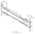
- FIG.1 shows an embodiment of a bracket assembly 10 adapted to a slide assembly 12 and a rack 14, wherein the slide assembly 12 can be mounted to the rack 14 by means of the bracket assembly 10.
- the bracket assembly 10 can be disposed adjacent to an end of a first rail 16 (e.g., the outer rail) of the slide assembly 12.
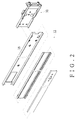
- the bracket assembly 10 comprises a bracket 18, an elastic member 20, a first arm 22, a second arm 24, and at least one inserting member 40.
- the first arm 22 is provided with a first hook portion 54
- the second arm 24 is provided with a second hook portion 64.
- the bracket 18 includes a first wall 28, a second wall 30 disposed opposite to the first wall 28, and a longitudinal body 32 connected between the first wall 28 and the second wall 30, wherein the longitudinal body 32 includes at least one assembling portion 33.
- the bracket 18 includes a first connecting base 34, a second connecting base 36 corresponding in position to the first connecting base 34, and an end plate 38 disposed on the longitudinal body 32.
- the end plate 38 is perpendicularly disposed adjacent to an end portion of the longitudinal body 32 of the bracket 18.
- the first connecting base 34 and the second connecting base 36 are disposed on the longitudinal body 32 of the bracket 18, wherein the first connecting base 34 is disposed adjacent to the first wall 28, and the second connecting base 36 is disposed adjacent to the second wall 30.
- the assembling portion 33 is preferably located between the first connecting base 34 and the second connecting base 36.
- the elastic member 20 is configured to urge at least one of the first hook portion 54 of the first arm 22 and the second hook portion 64 of the second arm 24 towards the bracket 18.
- the elastic member 20 includes a base plate 42, a first elastic portion 44, and a second elastic portion 46.
- the base plate 42 is correspondingly fit with the assembling portion 33 of the longitudinal body 32 of the bracket 18 so that the elastic member 20 can be disposed on the longitudinal body 32 of the bracket 18 and located between the first connecting base 34 and the second connecting base 36.
- the first elastic portion 44 and the second elastic portion 46 are uplifted from two opposite ends of the base plate 42, respectively.
- a predetermined included angle is formed between the first elastic portion 44 and the longitudinal body 32 of the bracket 18 for allowing the first elastic portion 44 to be pressed down elastically and thereby generate a first elastic force; also, a predetermined included angle is formed between the second elastic portion 46 and the longitudinal body 32 of the bracket 18 for allowing the second elastic portion 46 to be pressed down elastically and thereby generate a second elastic force.
- the first arm 22 is movably connected to the bracket 18.
- the first arm 22 is pivotally connected to the first connecting base 34 of the bracket 18 via a connecting element 47 and is rotatable in response to the first elastic force of the first elastic portion 44 of the elastic member 20.
- the first arm 22 includes a first portion 48 and a second portion 50 opposite to the first portion 48.
- the first portion 48 of the first arm 22 includes a first contact portion 52 correspondingly abutting against the first elastic portion 44 of the elastic member 20, wherein the first contact portion 52 can be bent to form an L-shape, but is not limited thereto.
- the second portion 50 of the first arm 22 corresponds in position to the end plate 38 of the bracket 18 and includes a first connecting portion 56, wherein the first hook portion 54 is also disposed on the second portion 50 of the first arm 22 and located close to the first connecting portion 56.
- the first hook portion 54 of the first arm 22 includes a hook surface 57 and extends in a horizontal direction, while the first connecting portion 56 extends in a vertical direction. It is noted that the second portion 50 of the first arm 22 can be moved toward and away from the end plate 38 of the bracket 18 in response to rotation of the first arm 22.
- the second arm 24 is movably connected to the bracket 18.
- the second arm 24 is pivotally connected to the second connecting base 36 of the bracket 18 via the connecting element 47 and is rotatable in response to the second elastic force of the second elastic portion 46 of the elastic member 20.
- the second arm 24 includes a first portion 58 and a second portion 60 opposite to the first portion 58.
- the first portion 58 of the second arm 24 includes a second contact portion 62 correspondingly abutting against the second elastic portion 46 of the elastic member 20, wherein the second contact portion 62 is bent to form an L-shape, but is not limited thereto.
- the second portion 60 of the second arm 24 corresponds in position to the end plate 38 of the bracket 18 and includes a second connecting portion 66, wherein the second hook portion 64 is also disposed on the second portion 60 of the second arm 24 and located close to the second connecting portion 66.
- the second hook portion 64 of the second arm 24 includes a hook surface 67 and extends in a horizontal direction, while the second connecting portion 66 extends in a vertical direction. It is noted that the second portion 60 of the second arm 24 can be moved toward and away from the end plate 38 of the bracket 18 in response to rotation of the second arm 24.
- the inserting member 40 is disposed on the end plate 38 of the bracket 18, wherein the inserting member 40 can be a circular stud, a square stud, or stud formed in other shapes. In other words, the inserting member 40 is not restricted to be formed as the circular stud illustrated in this embodiment.
- the bracket assembly 10 further comprises an operation member 26.
- the operation member 26 is assembled to or integrally formed with the first connecting portion 56 of the first arm 22 and the second connecting portion 66 of the second arm 24 and thus extends between the first connecting portion 56 of the first arm 22 and the second connecting portion 66 of the second arm 24.
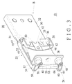
- the operation member 26 can be formed into a rod-like shank with a slightly curved operating surface 68, whereby user can simply operate the operation member 26 by fingers to rotate the first arm 22 and the second arm 24, for example, from a first position (as shown in FIG.3 ) to a second position (as shown in FIG.6 ).
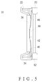
- the operation member 26 when the operation member 26 is not operated any more (i.e., when the force F is removed from the operating surface 68 of the operation member 26 ), the accumulated first elastic force and second elastic force are released to allow the first elastic portion 44 and the second elastic portion 46 to push against the first contact portion 52 of the first arm 22 and the second contact portion 62 of the second arm 24, respectively. Therefore, the first arm 22 and the second arm 24 are rotated back and drive the second portion 50 of the first arm 22 and the second portion 60 of the second arm 24 to move toward the end plate 38 of the bracket 18. Namely, the first arm 22 and the second arm 24 are rotated back from the second position (as shown in FIGS.6 and 7 ) to the first position (as shown in FIGS. 3 and 5 ). Simultaneously, the first elastic portion 44 and the second elastic portion 46 of the elastic member 20 return to their respect original states, i.e., uplifted from two opposite ends of the base plate 42 respectively.
- FIGS. 8 and 9 are schematic views showing how the bracket assembly 10 is assembled on the rack 14.
- the bracket assembly 10 is adapted to the rack 14 which includes at least one hole 15, wherein the hole 15 can be formed in a circle, square, or other shapes. That is to say that the hole 15 is not restricted to be formed in a circle as shown in this embodiment.
- the user To assemble the bracket 18 on the rack 14, the user initially operates the operation member 26 (as shown in FIG. 6 ) to move the second portion 50 of the first arm 22 and the second portion 60 of the second arm 24 away from the end plate 38 of the bracket 18, and simultaneously, the user moves the bracket assembly 10 toward the rack 14 in a direction D for allowing the inserting member 40 to be aligned with and received in the hole 15 of the rack 14. Consequently, the second portion 50 of the first arm 22 and the second portion 60 of the second arm 24 are spaced apart from the rack 14 by a distance during the insertion of the inserting member 40 into the hole 15 of the rack 14.
- the user stops operating the operation member 26 i.e., releases the operation member 26
- the first elastic portion 44 and the second elastic portion 46 return to their respect original states (as shown in FIG.3 ) due to their elasticity, and thus the first contact portion 52 and the second contact portion 62 are pushed against by the first elastic portion 44 and the second elastic portion 46, respectively, and thereby drive the first hook portion 54 of the second portion 50 of the first arm 22 and the second hook portion 64 of the second portion 60 of the second arm 24 to clasp the rack 14 by means of the hook surface 57 of the first hook portion 54 and the hook surface 67 of the second hook portion 64. Therefore, the bracket 18 is firmly assembled on the rack 14.
Landscapes
- Engineering & Computer Science (AREA)
- Computer Hardware Design (AREA)
- General Engineering & Computer Science (AREA)
- Microelectronics & Electronic Packaging (AREA)
- Drawers Of Furniture (AREA)
Claims (7)
- Un assemblage de support (10) pour une glissière, comprenant :un support (18) comportant un corps longitudinal (32) et une plaque d'extrémité (38) disposée sur le corps longitudinal (32) ;au moins un élément d'insertion (40) disposé sur la plaque d'extrémité (38) du support (18) ;un premier bras (22) relié de façon mobile au support (18), le premier bras (22) présentant une partie d'extrémité correspondant en position à la plaque d'extrémité (38) du support (18), la partie d'extrémité du premier bras (22) étant pourvue d'une première partie en forme de crochet (54) ; etun élément élastique (20) configuré pour pousser la première partie en forme de crochet (54) du premier bras (22) vers le support (18), dans lequel le support (18) comporte en outre une première base de liaison (34) et une seconde base de liaison (36) qui sont disposées sur le corps longitudinal (32) du support (18), dans lequel le premier bras (22) est relié de façon pivotante à la première base de liaison (34), et dans lequel l'assemblage de support (10) comprend en outre un second bras (24) relié de façon pivotante à la seconde base de liaison (36), caractérisé en ce que l'élément élastique (20) est disposé sur le support (18) et situé entre la première base de liaison (34) et la seconde base de liaison (36), dans lequel le second bras (24) présente une partie d'extrémité correspondant en position à la plaque d'extrémité (38) du support (18), dans lequel la partie d'extrémité du second bras (24) est pourvue d'une seconde partie en forme de crochet (64), et dans lequel l'élément élastique (20) est également configuré pour pousser la seconde partie en forme de crochet (64) du second bras (24) vers le support (18).
- L'assemblage de support (10) selon la revendication 1, dans lequel l'élément élastique (20) comporte en outre une plaque de soutien (42), une première partie élastique (44), et une seconde partie élastique (46), et dans lequel au moins la première partie élastique (44) ou la seconde partie élastique (46) est soulevée à partir d'une extrémité de la plaque de soutien (42).
- L'assemblage de support (10) selon la revendication 1, comprenant en outre un élément fonctionnel (26) relié entre le premier bras (22) et le second bras (24).
- L'assemblage de support (10) selon la revendication 1, dans lequel l'assemblage de support (10) est adapté à un châssis (14) qui comporte au moins un trou (15), et l'assemblage de support (10) comprend en outre un élément fonctionnel (26) relié entre le premier bras (22) et le second bras (24) ;dans lequel l'élément élastique (20) comporte une première partie élastique (44) et une seconde partie élastique (46) ;dans lequel le premier bras (22) comporte une première partie (48) et une seconde partie (50) opposée à la première partie (48), dans lequel la première partie (48) du premier bras (22) comporte une première partie de contact (52) en butée contre la première partie élastique (44) de l'élément élastique (20), et dans lequel la seconde partie (50) du premier bras (22) est la partie d'extrémité correspondant en position à la plaque d'extrémité (38) du support (18) et étant pourvue de la première partie en forme de crochet (54) ;dans lequel le second bras (24) comporte une première partie (58) et une seconde partie (60) opposée à la première partie (58), dans lequel la première partie (58) du second bras (24) comporte une seconde partie de contact (62) en butée contre la seconde partie élastique (46) de l'élément élastique (20), et dans lequel la seconde partie (60) du second bras (24) est la partie d'extrémité correspondant en position à la plaque d'extrémité (38) du support (18) et étant pourvue de la seconde partie en forme de crochet (64) ; etdans lequel, quand l'assemblage de support (10) est monté sur le châssis (14), le ou les éléments d'insertion (40) est inséré dans le ou les trous (15) du châssis (14), et pendant ce temps, la première partie en forme de crochet (54) de la seconde partie (50) du premier bras (22) et la seconde partie en forme de crochet (64) de la seconde partie (60) du second bras (24) serrent le châssis (14) du fait de la force élastique contre la première partie de contact (52) et la seconde partie de contact (62) fournie par la première partie élastique (44) et la seconde partie élastique (46).
- L'assemblage de support (10) selon la revendication 4, dans lequel l'élément élastique (20) comporte en outre une plaque de soutien (42), et la première partie élastique (44) et la seconde partie élastique (46) sont soulevées à partir de deux extrémité opposées de la plaque de soutien (42), respectivement.
- L'assemblage de support (10) selon la revendication 1, comprenant en outre un élément fonctionnel (26) ;dans lequel l'élément élastique (20) comporte une première partie élastique (44) et une seconde partie élastique (46) ;dans lequel le premier bras (22) comporte une première partie (48) et une seconde partie (50) opposée à la première partie (48), dans lequel la première partie (48) du premier bras (22) comporte une première partie de contact (52) en butée contre la première partie élastique (44) de l'élément élastique (20), dans lequel la seconde partie (50) du premier bras (22) est la partie d'extrémité correspondant en position à la plaque d'extrémité (38) du support (18) et étant pourvue de la première partie en forme de crochet (54), et dans lequel la seconde partie (50) du premier bras (22) est en outre munie d'une première partie de liaison (56) disposée près de la première partie en forme de crochet (54) ;dans lequel le second bras (24) comporte une première partie (58) et une seconde partie (60) opposée à la première partie (58), dans lequel la première partie (58) du second bras (24) comporte une seconde partie de contact (62) en butée contre la seconde partie élastique (46) de l'élément élastique (20), dans lequel la seconde partie (60) du second bras (24) est la partie d'extrémité correspondant en position à la plaque d'extrémité (38) du support (18) et étant pourvue de la seconde partie en forme de crochet (64), et dans lequel la seconde partie (60) du second bras (24) est en outre munie d'une seconde partie de liaison (66) disposée près de la seconde partie en forme de crochet (64) ; etdans lequel l'élément fonctionnel (26) est relié entre la première partie de liaison (56) du premier bras (22) et la seconde partie de liaison (66) du second bras (24).
- L'assemblage de support (10) selon la revendication 6, dans lequel l'élément élastique (20) comporte en outre une plaque de soutien (42), et dans lequel la première partie élastique (44) et la seconde partie élastique (46) sont soulevées à partir de deux extrémité opposées de la plaque de soutien (42), respectivement.
Priority Applications (1)
| Application Number | Priority Date | Filing Date | Title |
|---|---|---|---|
| EP14170151.6A EP2949238B1 (fr) | 2014-05-28 | 2014-05-28 | Ensemble support pour glissière |
Applications Claiming Priority (1)
| Application Number | Priority Date | Filing Date | Title |
|---|---|---|---|
| EP14170151.6A EP2949238B1 (fr) | 2014-05-28 | 2014-05-28 | Ensemble support pour glissière |
Publications (2)
| Publication Number | Publication Date |
|---|---|
| EP2949238A1 EP2949238A1 (fr) | 2015-12-02 |
| EP2949238B1 true EP2949238B1 (fr) | 2016-07-06 |
Family
ID=50897370
Family Applications (1)
| Application Number | Title | Priority Date | Filing Date |
|---|---|---|---|
| EP14170151.6A Active EP2949238B1 (fr) | 2014-05-28 | 2014-05-28 | Ensemble support pour glissière |
Country Status (1)
| Country | Link |
|---|---|
| EP (1) | EP2949238B1 (fr) |
Families Citing this family (3)
| Publication number | Priority date | Publication date | Assignee | Title |
|---|---|---|---|---|
| TWI640277B (zh) | 2017-09-15 | 2018-11-11 | 川湖科技股份有限公司 | 滑軌總成及其托架裝置 |
| CN111043122B (zh) * | 2020-01-14 | 2024-07-19 | 深圳市世宗自动化设备有限公司 | 喇叭支架保压治具 |
| CN111075812B (zh) * | 2020-01-14 | 2024-07-19 | 深圳市世宗自动化设备有限公司 | 翻转压紧机构及具有它的保压治具 |
Family Cites Families (4)
| Publication number | Priority date | Publication date | Assignee | Title |
|---|---|---|---|---|
| TWM255624U (en) | 2003-12-30 | 2005-01-11 | King Slide Works Co Ltd | Positioning device for sliding track bracket |
| TWI354528B (en) * | 2008-09-01 | 2011-12-11 | King Slide Works Co Ltd | Bracket assembly |
| TW201249310A (en) * | 2011-05-18 | 2012-12-01 | Hon Hai Prec Ind Co Ltd | Fixing apparatus for slide rail |
| US8727138B2 (en) * | 2011-11-04 | 2014-05-20 | International Business Machines Corporation | Toolless rail enabling simplified installation and removal |
-
2014
- 2014-05-28 EP EP14170151.6A patent/EP2949238B1/fr active Active
Also Published As
| Publication number | Publication date |
|---|---|
| EP2949238A1 (fr) | 2015-12-02 |
Similar Documents
| Publication | Publication Date | Title |
|---|---|---|
| US9237808B2 (en) | Bracket assembly for slide | |
| US9375087B1 (en) | Bracket and mounting device thereof | |
| US10935179B2 (en) | Wire pressing and holding device for an extension arm support mechanism | |
| US10455938B2 (en) | Slide rail assembly | |
| US9480183B2 (en) | Slide rail assembly | |
| US9066591B2 (en) | Fixing device for a slide assembly | |
| CN105041796A (zh) | 夹持紧固件装置 | |
| EP2949238B1 (fr) | Ensemble support pour glissière | |
| US20170232493A1 (en) | Bending tool and gripping device for manipulating the bending tool | |
| US20120222829A1 (en) | Pull bar device for a sunshade assembly | |
| CN104939545B (zh) | 滑轨的托架定位装置 | |
| EP2612572A1 (fr) | Dispositif d'installation d'ensemble coulissant | |
| JP3192322U (ja) | 位置決め装置 | |
| KR101544205B1 (ko) | 각도 조절식 차량시트 조립용 지그장치 | |
| JP3191618U (ja) | スライドレールシステム及び当該スライドレールシステムに用いられる連結装置 | |
| JP6595394B2 (ja) | ナットホルダ、ナット部材、締結具、取付工具及び製造方法 | |
| JP7195589B2 (ja) | 固定具 | |
| EP3032930B1 (fr) | Support et dispositif de montage de celui-ci | |
| EP2412578A1 (fr) | Dispositif pour fixer de manière amovible un support sur un dispositif électronique | |
| EP2813161A1 (fr) | Dispositif de fixation pour assemblage coulissant | |
| EP2979582B1 (fr) | Ensemble de rail de glissement | |
| JP2008232194A (ja) | 支持装置 | |
| US20140305271A1 (en) | Paper punch with adjustable punch seats | |
| EP2937017A1 (fr) | Dispositif de montage pour système de tiroir | |
| EP2813160B1 (fr) | Dispositif de fixation pour assemblage coulissant |
Legal Events
| Date | Code | Title | Description |
|---|---|---|---|
| 17P | Request for examination filed |
Effective date: 20150521 |
|
| AK | Designated contracting states |
Kind code of ref document: A1 Designated state(s): AL AT BE BG CH CY CZ DE DK EE ES FI FR GB GR HR HU IE IS IT LI LT LU LV MC MK MT NL NO PL PT RO RS SE SI SK SM TR |
|
| AX | Request for extension of the european patent |
Extension state: BA ME |
|
| PUAI | Public reference made under article 153(3) epc to a published international application that has entered the european phase |
Free format text: ORIGINAL CODE: 0009012 |
|
| GRAP | Despatch of communication of intention to grant a patent |
Free format text: ORIGINAL CODE: EPIDOSNIGR1 |
|
| INTG | Intention to grant announced |
Effective date: 20160115 |
|
| GRAS | Grant fee paid |
Free format text: ORIGINAL CODE: EPIDOSNIGR3 |
|
| GRAA | (expected) grant |
Free format text: ORIGINAL CODE: 0009210 |
|
| AK | Designated contracting states |
Kind code of ref document: B1 Designated state(s): AL AT BE BG CH CY CZ DE DK EE ES FI FR GB GR HR HU IE IS IT LI LT LU LV MC MK MT NL NO PL PT RO RS SE SI SK SM TR |
|
| REG | Reference to a national code |
Ref country code: GB Ref legal event code: FG4D |
|
| REG | Reference to a national code |
Ref country code: AT Ref legal event code: REF Ref document number: 810073 Country of ref document: AT Kind code of ref document: T Effective date: 20160715 Ref country code: CH Ref legal event code: EP |
|
| REG | Reference to a national code |
Ref country code: IE Ref legal event code: FG4D |
|
| REG | Reference to a national code |
Ref country code: DE Ref legal event code: R096 Ref document number: 602014002554 Country of ref document: DE |
|
| REG | Reference to a national code |
Ref country code: NL Ref legal event code: FP |
|
| REG | Reference to a national code |
Ref country code: LT Ref legal event code: MG4D |
|
| REG | Reference to a national code |
Ref country code: DE Ref legal event code: R079 Ref document number: 602014002554 Country of ref document: DE Free format text: PREVIOUS MAIN CLASS: A47B0088040000 Ipc: A47B0088400000 |
|
| REG | Reference to a national code |
Ref country code: AT Ref legal event code: MK05 Ref document number: 810073 Country of ref document: AT Kind code of ref document: T Effective date: 20160706 |
|
| PG25 | Lapsed in a contracting state [announced via postgrant information from national office to epo] |
Ref country code: IS Free format text: LAPSE BECAUSE OF FAILURE TO SUBMIT A TRANSLATION OF THE DESCRIPTION OR TO PAY THE FEE WITHIN THE PRESCRIBED TIME-LIMIT Effective date: 20161106 Ref country code: IT Free format text: LAPSE BECAUSE OF FAILURE TO SUBMIT A TRANSLATION OF THE DESCRIPTION OR TO PAY THE FEE WITHIN THE PRESCRIBED TIME-LIMIT Effective date: 20160706 Ref country code: NO Free format text: LAPSE BECAUSE OF FAILURE TO SUBMIT A TRANSLATION OF THE DESCRIPTION OR TO PAY THE FEE WITHIN THE PRESCRIBED TIME-LIMIT Effective date: 20161006 Ref country code: LT Free format text: LAPSE BECAUSE OF FAILURE TO SUBMIT A TRANSLATION OF THE DESCRIPTION OR TO PAY THE FEE WITHIN THE PRESCRIBED TIME-LIMIT Effective date: 20160706 Ref country code: HR Free format text: LAPSE BECAUSE OF FAILURE TO SUBMIT A TRANSLATION OF THE DESCRIPTION OR TO PAY THE FEE WITHIN THE PRESCRIBED TIME-LIMIT Effective date: 20160706 Ref country code: RS Free format text: LAPSE BECAUSE OF FAILURE TO SUBMIT A TRANSLATION OF THE DESCRIPTION OR TO PAY THE FEE WITHIN THE PRESCRIBED TIME-LIMIT Effective date: 20160706 Ref country code: FI Free format text: LAPSE BECAUSE OF FAILURE TO SUBMIT A TRANSLATION OF THE DESCRIPTION OR TO PAY THE FEE WITHIN THE PRESCRIBED TIME-LIMIT Effective date: 20160706 |
|
| PG25 | Lapsed in a contracting state [announced via postgrant information from national office to epo] |
Ref country code: PL Free format text: LAPSE BECAUSE OF FAILURE TO SUBMIT A TRANSLATION OF THE DESCRIPTION OR TO PAY THE FEE WITHIN THE PRESCRIBED TIME-LIMIT Effective date: 20160706 Ref country code: BE Free format text: LAPSE BECAUSE OF FAILURE TO SUBMIT A TRANSLATION OF THE DESCRIPTION OR TO PAY THE FEE WITHIN THE PRESCRIBED TIME-LIMIT Effective date: 20160706 Ref country code: LV Free format text: LAPSE BECAUSE OF FAILURE TO SUBMIT A TRANSLATION OF THE DESCRIPTION OR TO PAY THE FEE WITHIN THE PRESCRIBED TIME-LIMIT Effective date: 20160706 Ref country code: PT Free format text: LAPSE BECAUSE OF FAILURE TO SUBMIT A TRANSLATION OF THE DESCRIPTION OR TO PAY THE FEE WITHIN THE PRESCRIBED TIME-LIMIT Effective date: 20161107 Ref country code: AT Free format text: LAPSE BECAUSE OF FAILURE TO SUBMIT A TRANSLATION OF THE DESCRIPTION OR TO PAY THE FEE WITHIN THE PRESCRIBED TIME-LIMIT Effective date: 20160706 Ref country code: SE Free format text: LAPSE BECAUSE OF FAILURE TO SUBMIT A TRANSLATION OF THE DESCRIPTION OR TO PAY THE FEE WITHIN THE PRESCRIBED TIME-LIMIT Effective date: 20160706 Ref country code: ES Free format text: LAPSE BECAUSE OF FAILURE TO SUBMIT A TRANSLATION OF THE DESCRIPTION OR TO PAY THE FEE WITHIN THE PRESCRIBED TIME-LIMIT Effective date: 20160706 |
|
| REG | Reference to a national code |
Ref country code: DE Ref legal event code: R097 Ref document number: 602014002554 Country of ref document: DE |
|
| PG25 | Lapsed in a contracting state [announced via postgrant information from national office to epo] |
Ref country code: EE Free format text: LAPSE BECAUSE OF FAILURE TO SUBMIT A TRANSLATION OF THE DESCRIPTION OR TO PAY THE FEE WITHIN THE PRESCRIBED TIME-LIMIT Effective date: 20160706 Ref country code: RO Free format text: LAPSE BECAUSE OF FAILURE TO SUBMIT A TRANSLATION OF THE DESCRIPTION OR TO PAY THE FEE WITHIN THE PRESCRIBED TIME-LIMIT Effective date: 20160706 |
|
| PLBE | No opposition filed within time limit |
Free format text: ORIGINAL CODE: 0009261 |
|
| STAA | Information on the status of an ep patent application or granted ep patent |
Free format text: STATUS: NO OPPOSITION FILED WITHIN TIME LIMIT |
|
| PG25 | Lapsed in a contracting state [announced via postgrant information from national office to epo] |
Ref country code: SK Free format text: LAPSE BECAUSE OF FAILURE TO SUBMIT A TRANSLATION OF THE DESCRIPTION OR TO PAY THE FEE WITHIN THE PRESCRIBED TIME-LIMIT Effective date: 20160706 Ref country code: BG Free format text: LAPSE BECAUSE OF FAILURE TO SUBMIT A TRANSLATION OF THE DESCRIPTION OR TO PAY THE FEE WITHIN THE PRESCRIBED TIME-LIMIT Effective date: 20161006 Ref country code: DK Free format text: LAPSE BECAUSE OF FAILURE TO SUBMIT A TRANSLATION OF THE DESCRIPTION OR TO PAY THE FEE WITHIN THE PRESCRIBED TIME-LIMIT Effective date: 20160706 Ref country code: CZ Free format text: LAPSE BECAUSE OF FAILURE TO SUBMIT A TRANSLATION OF THE DESCRIPTION OR TO PAY THE FEE WITHIN THE PRESCRIBED TIME-LIMIT Effective date: 20160706 Ref country code: SM Free format text: LAPSE BECAUSE OF FAILURE TO SUBMIT A TRANSLATION OF THE DESCRIPTION OR TO PAY THE FEE WITHIN THE PRESCRIBED TIME-LIMIT Effective date: 20160706 |
|
| 26N | No opposition filed |
Effective date: 20170407 |
|
| PG25 | Lapsed in a contracting state [announced via postgrant information from national office to epo] |
Ref country code: LU Free format text: LAPSE BECAUSE OF NON-PAYMENT OF DUE FEES Effective date: 20170531 Ref country code: SI Free format text: LAPSE BECAUSE OF FAILURE TO SUBMIT A TRANSLATION OF THE DESCRIPTION OR TO PAY THE FEE WITHIN THE PRESCRIBED TIME-LIMIT Effective date: 20160706 |
|
| REG | Reference to a national code |
Ref country code: CH Ref legal event code: PL |
|
| PG25 | Lapsed in a contracting state [announced via postgrant information from national office to epo] |
Ref country code: MC Free format text: LAPSE BECAUSE OF FAILURE TO SUBMIT A TRANSLATION OF THE DESCRIPTION OR TO PAY THE FEE WITHIN THE PRESCRIBED TIME-LIMIT Effective date: 20160706 |
|
| REG | Reference to a national code |
Ref country code: IE Ref legal event code: MM4A |
|
| PG25 | Lapsed in a contracting state [announced via postgrant information from national office to epo] |
Ref country code: LI Free format text: LAPSE BECAUSE OF NON-PAYMENT OF DUE FEES Effective date: 20170531 Ref country code: CH Free format text: LAPSE BECAUSE OF NON-PAYMENT OF DUE FEES Effective date: 20170531 |
|
| REG | Reference to a national code |
Ref country code: FR Ref legal event code: ST Effective date: 20180131 |
|
| PG25 | Lapsed in a contracting state [announced via postgrant information from national office to epo] |
Ref country code: LU Free format text: LAPSE BECAUSE OF NON-PAYMENT OF DUE FEES Effective date: 20170528 |
|
| PG25 | Lapsed in a contracting state [announced via postgrant information from national office to epo] |
Ref country code: IE Free format text: LAPSE BECAUSE OF NON-PAYMENT OF DUE FEES Effective date: 20170528 |
|
| PG25 | Lapsed in a contracting state [announced via postgrant information from national office to epo] |
Ref country code: FR Free format text: LAPSE BECAUSE OF NON-PAYMENT OF DUE FEES Effective date: 20170531 |
|
| PG25 | Lapsed in a contracting state [announced via postgrant information from national office to epo] |
Ref country code: MT Free format text: LAPSE BECAUSE OF NON-PAYMENT OF DUE FEES Effective date: 20170528 |
|
| PG25 | Lapsed in a contracting state [announced via postgrant information from national office to epo] |
Ref country code: AL Free format text: LAPSE BECAUSE OF FAILURE TO SUBMIT A TRANSLATION OF THE DESCRIPTION OR TO PAY THE FEE WITHIN THE PRESCRIBED TIME-LIMIT Effective date: 20160706 |
|
| PG25 | Lapsed in a contracting state [announced via postgrant information from national office to epo] |
Ref country code: HU Free format text: LAPSE BECAUSE OF FAILURE TO SUBMIT A TRANSLATION OF THE DESCRIPTION OR TO PAY THE FEE WITHIN THE PRESCRIBED TIME-LIMIT; INVALID AB INITIO Effective date: 20140528 |
|
| PG25 | Lapsed in a contracting state [announced via postgrant information from national office to epo] |
Ref country code: CY Free format text: LAPSE BECAUSE OF FAILURE TO SUBMIT A TRANSLATION OF THE DESCRIPTION OR TO PAY THE FEE WITHIN THE PRESCRIBED TIME-LIMIT Effective date: 20160706 |
|
| PG25 | Lapsed in a contracting state [announced via postgrant information from national office to epo] |
Ref country code: MK Free format text: LAPSE BECAUSE OF FAILURE TO SUBMIT A TRANSLATION OF THE DESCRIPTION OR TO PAY THE FEE WITHIN THE PRESCRIBED TIME-LIMIT Effective date: 20160706 |
|
| PG25 | Lapsed in a contracting state [announced via postgrant information from national office to epo] |
Ref country code: TR Free format text: LAPSE BECAUSE OF FAILURE TO SUBMIT A TRANSLATION OF THE DESCRIPTION OR TO PAY THE FEE WITHIN THE PRESCRIBED TIME-LIMIT Effective date: 20160706 |
|
| PG25 | Lapsed in a contracting state [announced via postgrant information from national office to epo] |
Ref country code: GR Free format text: LAPSE BECAUSE OF FAILURE TO SUBMIT A TRANSLATION OF THE DESCRIPTION OR TO PAY THE FEE WITHIN THE PRESCRIBED TIME-LIMIT Effective date: 20160706 |
|
| PGFP | Annual fee paid to national office [announced via postgrant information from national office to epo] |
Ref country code: DE Payment date: 20250311 Year of fee payment: 12 |
|
| PGFP | Annual fee paid to national office [announced via postgrant information from national office to epo] |
Ref country code: GB Payment date: 20260310 Year of fee payment: 13 |
|
| PGFP | Annual fee paid to national office [announced via postgrant information from national office to epo] |
Ref country code: NL Payment date: 20260313 Year of fee payment: 13 |