EP2949470B1 - Dispositif de nettoyage de têtes d'impression - Google Patents
Dispositif de nettoyage de têtes d'impression Download PDFInfo
- Publication number
- EP2949470B1 EP2949470B1 EP15164092.7A EP15164092A EP2949470B1 EP 2949470 B1 EP2949470 B1 EP 2949470B1 EP 15164092 A EP15164092 A EP 15164092A EP 2949470 B1 EP2949470 B1 EP 2949470B1
- Authority
- EP
- European Patent Office
- Prior art keywords
- printhead
- nozzles
- housing
- array
- printing
- Prior art date
- Legal status (The legal status is an assumption and is not a legal conclusion. Google has not performed a legal analysis and makes no representation as to the accuracy of the status listed.)
- Active
Links
Images




Classifications
-
- B—PERFORMING OPERATIONS; TRANSPORTING
- B41—PRINTING; LINING MACHINES; TYPEWRITERS; STAMPS
- B41J—TYPEWRITERS; SELECTIVE PRINTING MECHANISMS, i.e. MECHANISMS PRINTING OTHERWISE THAN FROM A FORME; CORRECTION OF TYPOGRAPHICAL ERRORS
- B41J2/00—Typewriters or selective printing mechanisms characterised by the printing or marking process for which they are designed
- B41J2/005—Typewriters or selective printing mechanisms characterised by the printing or marking process for which they are designed characterised by bringing liquid or particles selectively into contact with a printing material
- B41J2/01—Ink jet
- B41J2/135—Nozzles
- B41J2/165—Prevention or detection of nozzle clogging, e.g. cleaning, capping or moistening for nozzles
- B41J2/16517—Cleaning of print head nozzles
- B41J2/1652—Cleaning of print head nozzles by driving a fluid through the nozzles to the outside thereof, e.g. by applying pressure to the inside or vacuum at the outside of the print head
- B41J2/16532—Cleaning of print head nozzles by driving a fluid through the nozzles to the outside thereof, e.g. by applying pressure to the inside or vacuum at the outside of the print head by applying vacuum only
-
- B—PERFORMING OPERATIONS; TRANSPORTING
- B41—PRINTING; LINING MACHINES; TYPEWRITERS; STAMPS
- B41J—TYPEWRITERS; SELECTIVE PRINTING MECHANISMS, i.e. MECHANISMS PRINTING OTHERWISE THAN FROM A FORME; CORRECTION OF TYPOGRAPHICAL ERRORS
- B41J2/00—Typewriters or selective printing mechanisms characterised by the printing or marking process for which they are designed
- B41J2/005—Typewriters or selective printing mechanisms characterised by the printing or marking process for which they are designed characterised by bringing liquid or particles selectively into contact with a printing material
- B41J2/01—Ink jet
- B41J2/135—Nozzles
- B41J2/165—Prevention or detection of nozzle clogging, e.g. cleaning, capping or moistening for nozzles
- B41J2/16505—Caps, spittoons or covers for cleaning or preventing drying out
- B41J2/16508—Caps, spittoons or covers for cleaning or preventing drying out connected with the printer frame
-
- B—PERFORMING OPERATIONS; TRANSPORTING
- B41—PRINTING; LINING MACHINES; TYPEWRITERS; STAMPS
- B41J—TYPEWRITERS; SELECTIVE PRINTING MECHANISMS, i.e. MECHANISMS PRINTING OTHERWISE THAN FROM A FORME; CORRECTION OF TYPOGRAPHICAL ERRORS
- B41J2/00—Typewriters or selective printing mechanisms characterised by the printing or marking process for which they are designed
- B41J2/005—Typewriters or selective printing mechanisms characterised by the printing or marking process for which they are designed characterised by bringing liquid or particles selectively into contact with a printing material
- B41J2/01—Ink jet
- B41J2/135—Nozzles
- B41J2/14—Structure thereof only for on-demand ink jet heads
- B41J2002/14362—Assembling elements of heads
Definitions
- the invention discloses a device for cleaning ink-jet printheads.
- the invention is particularly intended for use in the field of industrial printing, particularly for the marking of packaging, without excluding however other types of use, by way of example, within domestic or employment environments.
- the packaging, or other objects to be printed are carried horizontally along a conveyor next to which the printing apparatus is arranged.
- Such apparatuses include a printing member which comprises at least one printhead contained in a special housing together with the control electronics and exhibiting an opening to allow the nozzles array of the printhead to face outwards thus enabling the printing.
- the cleaning is performed via a so called purging operation, during which the ink is caused to pass through the nozzles without performing any printing, thereby allowing escape of air bubbles and discharge of dirt.
- the nozzles array is disposed on a horizontal plane above the printing conveyor so that the printing can be performed on top of the packaging (or the like).
- the system of the known type applied to the apparatuses herein provides first and foremost to stop printing operations when a purging cycle is being performed.
- the printing member which contains the printhead, is moved from its operational position wherein it substantially surmounts the transit line of the packaging, to a position in which it is placed above a collection tray.
- the purging procedure is activated and the purge ink falls into the tray. Then, a removal element intervenes mechanically to remove the residual patina of purge ink.
- the system of the known type does not allow to recover or rather, to re-use the purge ink.
- WO 2010101075 discloses a liquid jetting recording device having a liquid jetting head provided with a set of nozzle ports and with two suction channels having respective suction ports located at the longitudinal ends of the set of nozzle ports.
- JP 2011235495 print apparatus having a plurality of components arranged at different levels.
- a printhead is placed having three nozzles, below which a first layer is provided having three holes, facing respective nozzles.
- a second layer is provided comprising holes, facing the holes of the first layer and connected to aspiration openings by means of small channels.
- JP 2011178040 describes a print device provided with an ejection system intended to improve the dropping of the ink. Under a printhead, a chamber is provided that is crossed by the drops. At a longitudinal end of the chamber, a fan is provided in order to blow air horizontally in the chamber.
- the technical task at the base of the present invention is to provide a device for the cleaning of printheads which overcomes the drawbacks listed hereinabove.
- An object of the invention within this aim is to propose a cleaning device which enables the effective removal of purge ink regardless of the spatial orientation of the printhead and particularly of the nozzle array thereof.
- a further object of the invention herein is to make available a device which allows recovery of the purge ink.
- Another object of the invention is to make available a device for protecting the printhead from impacts, scratches, or dust.
- the device 1 proposed has been devised for cleaning the ink jet printheads 2 of the type comprising a nozzles array which may be like the ones already briefly described in the explanation of the prior art.
- the invention does not only concern the use in the industrial sector, with particular reference to the marking or printing on labels for which it may also find application in domestic or working environments.
- the device 1 enables to perform the above purge cycles of the printhead 2, thereby cleaning effectively the latter without dirtying the surrounding environment or interrupting the production.
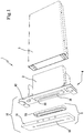
- the device 1 can be implemented within a printing apparatus 2, 3, 10, whose printing member is represented in its essential parts in Figure 1 .
- the printhead 2 of the example shown in Figure 1 is of the type solidly constraint with the control logic and exhibits one printing face 20, preferably planar, at the free end of a projecting portion, which includes the array of nozzles 21 from which the ink is ejected, for example via a technology of the piezoelectric type or of other known systems.
- the array 21 preferably has a substantially linear shape.
- the device 1 proposed, in its most general form, includes first of all a main unit 10 provided with a housing 100 for a printhead 2.
- the housing 100 preferably defines a concavity substantially prismatic, so as to receive part of said projecting portion of the printhead 2, which is typically substantially polygonal.
- the printing member may comprise a containment and protection housing 3, provided for holding the printhead 2, which housing is closed on one side by the main unit 10 of the device 1, to define a unitary block (see Figure 1 ).
- the printing member is in turn part of a printing apparatus which can also be of the known type, apart from the device 1 of the invention.
- the housing 100 of the main unit 10 includes an inlet 11 conformed so as to fit to size the aforementioned projecting portion of the printhead 2, which issue will be better detailed in a later section.
- the housing 100 is provided with a passing slot 12, for example in the form of a slit, which is destined to face the array of nozzles 21 of the printhead 2, so as to allow the passage of the printing ink.
- a passing slot 12 for example in the form of a slit, which is destined to face the array of nozzles 21 of the printhead 2, so as to allow the passage of the printing ink.
- the printhead 2 is coupled to the main unit 10 of the device 1 in such a manner that the array 21 is placed directly in front of the slot 12, thereby allowing the jet of the ink to be directed outwards the device 1, towards the article to be marked or printed.
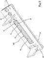
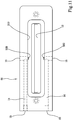
- one or more draw openings 13 are defined within the housing 100, which draw openins (13) are adapted to be put into fluid-dynamic communication with a suction source (see figure 2 ).
- the draw openings 13 are placed substantially in the plane in which said array of nozzles 21 lays, thereby intercepting the purge ink as soon it flows out from the printhead 2.
- the draw openings 13 are placed on two opposite sides of the housing 100, being therefore arranged on opposite sides of the printing face 20 of the printhead 2 and therefore of the array 21 of nozzles.
- the projecting portion of the printhead 2 is substantially parallelepiped, for which reason also the housing 100 is generically parallelepiped.
- the draw openings 13 are arranged along the longest sides of the housing 100, which sides are destined, in use, to flank the array 21 of nozzles.
- the purge ink flows away from the housing 100 and from the main unit 10 of the device 1 via one or more conduits 14 which extend between at least one outlet 15 being formed on the perimeter of the unit 10, and the draw openings 13.
- the outlet 15 is connectable to the suction source which can be, by way of example, a pump or a depression source of the type with compressed air.
- the device comprises a support bracket 4 to which the printhead 2 can be removably fastened.
- the support bracket 4 may comprise a plate-shape wall 40 equipped with a passage 41 in which the projecting portion of the printhead 2 can be inserted, so that the above mentioned printing face 20 can cross therethrough and then be arranged within the housing 100.
- the passage 41 of the support bracket 4 substantially matches to the profile of the printing face 20, and the projecting portion, so as to fit to size, as already described above.
- the passage 41 can be substantially rectangular.
- the device 1 provided herein also comprises a covering element 5 provided with a cavity 50, which cavity 50 partially defines said housing 100, at the bottom of which cavity 50, aforementioned slot 12 is fashioned.
- the covering element is applied, for example glued, to said plate-shaped wall 40 of the support bracket 4, so as to define the main unit 10 of the device 1.
- the shaped passage 41 of the support bracket 4 defines said mouth of the housing 100, which housing 100 is internally defined by the cavity 50, within said housing 100 being inserted the printing face 20 of the cartridge.
- the covering element may comprise an external body 51, for example, a plate-shaped body, intended for contact with the article to be printed, inside of which said conduits (see Figures 5 , 8 , 9 and 11 ), are obtained.
- an external body 51 for example, a plate-shaped body, intended for contact with the article to be printed, inside of which said conduits (see Figures 5 , 8 , 9 and 11 ), are obtained.
- the external body 51 is provided with a recess 510 which defines the bottom of the housing 100, which recess 510 is provided with inlet holes 520 being in direct communication with the conduits.
- the device 1 proposed also includes an interposition member 53, preferably annular, inserted into the recess 510 of the external body 51, so as to define with it aforesaid covering element 5.
- the interposition member 53 laterally defines the cavity 50 of the covering element 5 and thus also that of the housing 100 which is obtained following the connection between the support bracket 4 and the covering element 5.
- the interposition member 53 is provided to be arranged between the bottom of the recess 510 and the wall 40 of the support bracket 4 provided with the passage 41.
- the member 53 of interposition fits to size in the recess 510, opposite and preferably in contact with the inner wall 40 having same thickness of the recess 510.
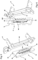
- a first embodiment is shown in Figures 3, 4 and 5 .
- Such shaped elements are placed upstream relative to said inlet holes 520 along the fluid-dynamic path followed by the purge ink from the housing 100, along the conduits, up to the outlets.
- the shaped elements 54 are arranged opposite to the largest sides of the recess 510.
- each draw opening is defined between two shaped elements 54 following application of the external body 51 to the support bracket 4.
- each draw opening is defined and bounded by the bottom of the recess 510, the aforementioned wall 40 of the support bracket 4 and two moulded elements.
- the elements 54 may have a triangular shape so as to define a passageway for facilitating the suction of the purge ink. Said elements 54 may also have a conical, elliptical, circular, oval and half-moon shape.
- such first embodiment exhibits a useful aspect which is applicable to the printing of particularly large codes and/or writings or in case of a four-color printing.
- outlets of the conduits are formed only on an outer edge with longitudinal end, that is to say on one of the outer short sides.
- the device 1 of the invention includes more main units 10 arranged side by side relative to the long side.
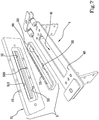
- the further embodiments join the aspect of providing an interposition member 53 which conforms the shaped elements 55, having the function of defining the draw openings 13, as the moulded elements 53 described hereinabove.
- the shaped elements 55 are formed in the inner side of the interposition member 53, which comes into contact with the bottom of the recess 510, with which it defines the draw openings 13 exactly through the shaped elements 55.
- the interposition member 53 exhibits shaped elements 55 which are conformed likewise the shape elements of the external body 51 as described in the first embodiment, thereby defining a sort of passageway of the type mentioned above.
- the holes 520 are arranged opposite the draw openings 13, that is, opposite the shaped elements 55.
- Said shaped elements 55 may also have a conical, elliptical, circular, oval and half-moon shape.
- the figure 8 and figure 9 represent variants of an external body 51 which can be used both in relation to the first and second embodiment of the device 1.
- the internal conduits of the body 51 lead to respective openings (see figure 8 ), located on the peripheral edge.
- conduits are also joined by a cross connection leading to an outlet 15 arranged at the planar surface which is distanced from the edges.
- the inlet holes 520 also open into the outlet 15, this time on the edge of the longest side.
- the shaped elements 55 formed on the interposition member 53 do not completely protrude therefrom.
- the external body 51 preferably exhibits two holes 520 opposed one to another, arranged by way of example, in a median position on the respective side, and each longest side of the interposition member 53 has two shaped elements 55 placed side by side which together form a triangular shaped element converging towards the respective hole 520.
- the hole can exhibit its own exit 15 on the outer edge of the longer side of the body 51 which can be plugged or connected to the suction source.
- the disclosed device operates as follows.
- the printing member is arranged such that the slot 12 of the outlet 15 of the ink jet is facing towards the zone of passage of the surfaces to be printed.
- the slot 12 can be faced downwards.
- a processing unit 10 periodically controls a purging cycle during which, as explained, the purge ink is made to pass through the printhead 2 and then comes out of the array 21 of nozzles.
- the suction source is activated, then, the purge ink is taken from inside the housing 100 and made to exit by the main unit 10 of the printing member via the aforementioned outlet opening, 15 prior to leaking through the slot 12.
- the ink bleed is sent to a filter, which traps any impurities, from which then comes to a manifold.
- the collector is connected by pneumatic means to the tank of the printhead 2 so that the ink can be re-used.
- both the array 21 of nozzles and the surface of the printing face 20 are free of any residual ink and the surrounding environment, particularly the conveyor and the articles to be marked or printed, did not become dirty so that printing can be smoothly continued.
- the purge ink is not wasted but re-used.
Landscapes
- Ink Jet (AREA)
Claims (12)
- Dispositif (1) de nettoyage de têtes d'impression, comprenant une unité principale (10) comportant un logement (100) pour au moins une tête d'impression (2) comprenant une matrice de buses (21), ledit logement (100) étant pourvu d'une fente (12) pour le passage (41) de l'encre d'impression et destinée à faire face à ladite matrice de buses (21) de la tête d'impression (2), dans lequel une ou plusieurs ouvertures de prélèvement (13) sont définies dans ledit logement (100), lesdites ouvertures (13) pouvant être mises en communication fluidique et dynamique avec une source d'aspiration ;
lesdites ouvertures de prélèvement (13) sont situées au moins sur deux côtés opposés du logement (100) ; et ledit dispositif étant caractérisé en ce que le logement (100) est allongé et lesdits côtés opposés sont les côtés les plus longs étant destinés à flanquer ladite matrice (21) de buses. - Dispositif (1) selon la revendication précédente, dans lequel lesdites ouvertures de prélèvement (13) sont substantiellement disposées dans un plan dans lequel repose ladite matrice (21) de buses.
- Dispositif (1) selon au moins l'une des revendications précédentes, dans lequel ladite unité (10) inclut au moins un conduit (14) se prolongeant entre au moins une sortie (15), pouvant être reliée à ladite source d'aspiration, et les ouvertures de prélèvement (13).
- Dispositif (1) selon au moins l'une des revendications précédentes, comprenant un étrier de support (4) auquel une tête d'impression (2) peut être fixée, ledit étrier de support (4) étant pourvu d'un passage (41) dans lequel peut être introduit un côté d'impression (20) de la tête d'impression (2) en correspondance de laquelle est disposée la matrice (21) de buses.
- Dispositif (1) selon la revendication précédente, dans lequel ledit passage (41) est substantiellement façonné de façon complémentaire au dit côté d'impression (20).
- Dispositif (1) selon au moins l'une des revendications précédentes, comprenant un élément de couverture (5) comportant une cavité (50) pour recevoir un côté d'impression (20) de la tête d'impression (2) en correspondance de laquelle est disposée une matrice (21) de buses, ladite cavité (50) comprenant un fond dans lequel est prévue ladite fente (12).
- Dispositif (1) selon les deux revendications précédentes, dans lequel ledit élément de couverture (5) est appliqué au dit étrier (4) de sorte à définir ladite unité principale (10).
- Dispositif (1) selon la revendication 5 ou 6, dans lequel ledit élément de couverture (5) comprend un corps extérieur (51) dans lequel est prévu ledit conduit, ledit corps (51) comportant aussi un renfoncement (510) sur le fond duquel est réalisée la fente (12).
- Dispositif (1) selon la revendication précédente, dans lequel ledit renfoncement (510) est pourvu d'orifices (520) en communication avec ledit conduit (14).
- Dispositif (1) selon la revendication 8 ou la revendication 9, dans lequel, entre le fond du renfoncement (510) et une cloison (40) de l'étrier de support (4) dans laquelle est réalisé le passage (41), est disposé un nombre d'éléments façonnés (54, 55) entre lesquels sont définies (13) les ouvertures de prélèvement (13).
- Dispositif (1) selon la revendication précédente, dans lequel les éléments façonnés (54) émanent du fond du renfoncement (510), chaque ouverture de prélèvement étant définie et délimitée par le fond du renfoncement (510), par ladite cloison (40) de l'étrier de support (4) et par deux éléments façonnés.
- Dispositif (1) selon la revendication 11, dans lequel ladite unité principale (10) comprend au moins un organe d'interposition (53) introduit dans ledit renfoncement (510) du corps extérieur (51) de sorte à définir avec celui-ci ledit élément de couverture (5), l'organe d'interposition (53) façonnant lesdits éléments (55).
Applications Claiming Priority (1)
| Application Number | Priority Date | Filing Date | Title |
|---|---|---|---|
| ITMO20140120 | 2014-04-30 |
Publications (2)
| Publication Number | Publication Date |
|---|---|
| EP2949470A1 EP2949470A1 (fr) | 2015-12-02 |
| EP2949470B1 true EP2949470B1 (fr) | 2019-11-27 |
Family
ID=51136626
Family Applications (1)
| Application Number | Title | Priority Date | Filing Date |
|---|---|---|---|
| EP15164092.7A Active EP2949470B1 (fr) | 2014-04-30 | 2015-04-17 | Dispositif de nettoyage de têtes d'impression |
Country Status (1)
| Country | Link |
|---|---|
| EP (1) | EP2949470B1 (fr) |
Families Citing this family (1)
| Publication number | Priority date | Publication date | Assignee | Title |
|---|---|---|---|---|
| EP3853028B1 (fr) | 2018-09-21 | 2023-07-19 | System Ceramics S.p.A. | Dispositif de nettoyage pour têtes d'impression |
Family Cites Families (3)
| Publication number | Priority date | Publication date | Assignee | Title |
|---|---|---|---|---|
| JP2010208053A (ja) * | 2009-03-06 | 2010-09-24 | Sii Printek Inc | 液体噴射ヘッド、液体噴射記録装置及び液体噴射記録装置の使用方法 |
| JP2011178040A (ja) * | 2010-03-01 | 2011-09-15 | Seiko Epson Corp | 液体噴射ヘッド、液体噴射ヘッドユニット及び液体噴射装置 |
| JP2011235495A (ja) * | 2010-05-07 | 2011-11-24 | Ibiden Co Ltd | インクジェットヘッド |
-
2015
- 2015-04-17 EP EP15164092.7A patent/EP2949470B1/fr active Active
Non-Patent Citations (1)
| Title |
|---|
| None * |
Also Published As
| Publication number | Publication date |
|---|---|
| EP2949470A1 (fr) | 2015-12-02 |
Similar Documents
| Publication | Publication Date | Title |
|---|---|---|
| US9498962B2 (en) | Printing device | |
| KR20180135009A (ko) | 정제 인쇄 장치 및 세정 방법 | |
| US8388103B2 (en) | Flushing apparatus for inkjet printer | |
| KR930007664A (ko) | 개선된 회복동작을 행할수 있는 잉크제트장치 | |
| JP2009119778A5 (fr) | ||
| JP2009291977A (ja) | インクジェットプリンタ、インクミスト液状化部材、およびそのインクジェットプリンタを用いたインクミスト液状化方法 | |
| JP5029191B2 (ja) | キャップ装置、及び液体噴射装置 | |
| EP2949470A1 (fr) | Dispositif de nettoyage de têtes d'impression | |
| CN107053850A (zh) | 喷墨打印机 | |
| US7004559B2 (en) | Method and apparatus for ink jet print head nozzle plate cleaning | |
| JP5778531B2 (ja) | インクジェットプリンタ、インク回収部材、及びインク回収方法 | |
| JP2007509786A (ja) | インクジェットプリントヘッドのくずの蓄積を減少させるための方法および装置 | |
| JP2016097969A (ja) | 自動車の窓ガラスを払拭するシステムのワイパーアーム用の洗浄液を側方に噴出するための装置 | |
| US8425024B2 (en) | Liquid ejection apparatus and printing apparatus | |
| US20110221838A1 (en) | Liquid ejecting head and liquid ejecting apparatus | |
| US9944081B2 (en) | Cleaning adapter and method for cleaning print heads | |
| CN115214235B (zh) | 记录装置 | |
| KR101385142B1 (ko) | 헤드청소장치 | |
| CN206520347U (zh) | 一种隐形防伪标签喷码机 | |
| JP4147878B2 (ja) | インクジェット記録装置のユニットの洗浄方法 | |
| JP2012170912A (ja) | 電子部品実装設備用の洗浄ツールおよび洗浄方法 | |
| JP2013091266A (ja) | インクジェット記録装置 | |
| US20240424741A1 (en) | Cleaning apparatus | |
| JP6722559B2 (ja) | インクジェットプリンタのクリーニング部およびインクジェットプリンタ | |
| JP6554983B2 (ja) | 液体噴射装置及びキャップ |
Legal Events
| Date | Code | Title | Description |
|---|---|---|---|
| AK | Designated contracting states |
Kind code of ref document: A1 Designated state(s): AL AT BE BG CH CY CZ DE DK EE ES FI FR GB GR HR HU IE IS IT LI LT LU LV MC MK MT NL NO PL PT RO RS SE SI SK SM TR |
|
| AX | Request for extension of the european patent |
Extension state: BA ME |
|
| PUAI | Public reference made under article 153(3) epc to a published international application that has entered the european phase |
Free format text: ORIGINAL CODE: 0009012 |
|
| 17P | Request for examination filed |
Effective date: 20160511 |
|
| RBV | Designated contracting states (corrected) |
Designated state(s): AL AT BE BG CH CY CZ DE DK EE ES FI FR GB GR HR HU IE IS IT LI LT LU LV MC MK MT NL NO PL PT RO RS SE SI SK SM TR |
|
| RIC1 | Information provided on ipc code assigned before grant |
Ipc: B41J 2/165 20060101AFI20190527BHEP Ipc: B41J 2/14 20060101ALI20190527BHEP |
|
| GRAP | Despatch of communication of intention to grant a patent |
Free format text: ORIGINAL CODE: EPIDOSNIGR1 |
|
| STAA | Information on the status of an ep patent application or granted ep patent |
Free format text: STATUS: GRANT OF PATENT IS INTENDED |
|
| INTG | Intention to grant announced |
Effective date: 20190724 |
|
| GRAS | Grant fee paid |
Free format text: ORIGINAL CODE: EPIDOSNIGR3 |
|
| GRAA | (expected) grant |
Free format text: ORIGINAL CODE: 0009210 |
|
| STAA | Information on the status of an ep patent application or granted ep patent |
Free format text: STATUS: THE PATENT HAS BEEN GRANTED |
|
| AK | Designated contracting states |
Kind code of ref document: B1 Designated state(s): AL AT BE BG CH CY CZ DE DK EE ES FI FR GB GR HR HU IE IS IT LI LT LU LV MC MK MT NL NO PL PT RO RS SE SI SK SM TR |
|
| REG | Reference to a national code |
Ref country code: GB Ref legal event code: FG4D |
|
| REG | Reference to a national code |
Ref country code: CH Ref legal event code: EP |
|
| REG | Reference to a national code |
Ref country code: AT Ref legal event code: REF Ref document number: 1206220 Country of ref document: AT Kind code of ref document: T Effective date: 20191215 |
|
| REG | Reference to a national code |
Ref country code: DE Ref legal event code: R096 Ref document number: 602015042370 Country of ref document: DE |
|
| REG | Reference to a national code |
Ref country code: IE Ref legal event code: FG4D |
|
| REG | Reference to a national code |
Ref country code: NL Ref legal event code: MP Effective date: 20191127 |
|
| REG | Reference to a national code |
Ref country code: LT Ref legal event code: MG4D |
|
| PG25 | Lapsed in a contracting state [announced via postgrant information from national office to epo] |
Ref country code: NL Free format text: LAPSE BECAUSE OF FAILURE TO SUBMIT A TRANSLATION OF THE DESCRIPTION OR TO PAY THE FEE WITHIN THE PRESCRIBED TIME-LIMIT Effective date: 20191127 Ref country code: SE Free format text: LAPSE BECAUSE OF FAILURE TO SUBMIT A TRANSLATION OF THE DESCRIPTION OR TO PAY THE FEE WITHIN THE PRESCRIBED TIME-LIMIT Effective date: 20191127 Ref country code: LV Free format text: LAPSE BECAUSE OF FAILURE TO SUBMIT A TRANSLATION OF THE DESCRIPTION OR TO PAY THE FEE WITHIN THE PRESCRIBED TIME-LIMIT Effective date: 20191127 Ref country code: NO Free format text: LAPSE BECAUSE OF FAILURE TO SUBMIT A TRANSLATION OF THE DESCRIPTION OR TO PAY THE FEE WITHIN THE PRESCRIBED TIME-LIMIT Effective date: 20200227 Ref country code: GR Free format text: LAPSE BECAUSE OF FAILURE TO SUBMIT A TRANSLATION OF THE DESCRIPTION OR TO PAY THE FEE WITHIN THE PRESCRIBED TIME-LIMIT Effective date: 20200228 Ref country code: LT Free format text: LAPSE BECAUSE OF FAILURE TO SUBMIT A TRANSLATION OF THE DESCRIPTION OR TO PAY THE FEE WITHIN THE PRESCRIBED TIME-LIMIT Effective date: 20191127 Ref country code: BG Free format text: LAPSE BECAUSE OF FAILURE TO SUBMIT A TRANSLATION OF THE DESCRIPTION OR TO PAY THE FEE WITHIN THE PRESCRIBED TIME-LIMIT Effective date: 20200227 Ref country code: FI Free format text: LAPSE BECAUSE OF FAILURE TO SUBMIT A TRANSLATION OF THE DESCRIPTION OR TO PAY THE FEE WITHIN THE PRESCRIBED TIME-LIMIT Effective date: 20191127 |
|
| PG25 | Lapsed in a contracting state [announced via postgrant information from national office to epo] |
Ref country code: HR Free format text: LAPSE BECAUSE OF FAILURE TO SUBMIT A TRANSLATION OF THE DESCRIPTION OR TO PAY THE FEE WITHIN THE PRESCRIBED TIME-LIMIT Effective date: 20191127 Ref country code: RS Free format text: LAPSE BECAUSE OF FAILURE TO SUBMIT A TRANSLATION OF THE DESCRIPTION OR TO PAY THE FEE WITHIN THE PRESCRIBED TIME-LIMIT Effective date: 20191127 Ref country code: IS Free format text: LAPSE BECAUSE OF FAILURE TO SUBMIT A TRANSLATION OF THE DESCRIPTION OR TO PAY THE FEE WITHIN THE PRESCRIBED TIME-LIMIT Effective date: 20200327 |
|
| PG25 | Lapsed in a contracting state [announced via postgrant information from national office to epo] |
Ref country code: AL Free format text: LAPSE BECAUSE OF FAILURE TO SUBMIT A TRANSLATION OF THE DESCRIPTION OR TO PAY THE FEE WITHIN THE PRESCRIBED TIME-LIMIT Effective date: 20191127 |
|
| PG25 | Lapsed in a contracting state [announced via postgrant information from national office to epo] |
Ref country code: ES Free format text: LAPSE BECAUSE OF FAILURE TO SUBMIT A TRANSLATION OF THE DESCRIPTION OR TO PAY THE FEE WITHIN THE PRESCRIBED TIME-LIMIT Effective date: 20191127 Ref country code: CZ Free format text: LAPSE BECAUSE OF FAILURE TO SUBMIT A TRANSLATION OF THE DESCRIPTION OR TO PAY THE FEE WITHIN THE PRESCRIBED TIME-LIMIT Effective date: 20191127 Ref country code: RO Free format text: LAPSE BECAUSE OF FAILURE TO SUBMIT A TRANSLATION OF THE DESCRIPTION OR TO PAY THE FEE WITHIN THE PRESCRIBED TIME-LIMIT Effective date: 20191127 Ref country code: DK Free format text: LAPSE BECAUSE OF FAILURE TO SUBMIT A TRANSLATION OF THE DESCRIPTION OR TO PAY THE FEE WITHIN THE PRESCRIBED TIME-LIMIT Effective date: 20191127 Ref country code: EE Free format text: LAPSE BECAUSE OF FAILURE TO SUBMIT A TRANSLATION OF THE DESCRIPTION OR TO PAY THE FEE WITHIN THE PRESCRIBED TIME-LIMIT Effective date: 20191127 Ref country code: PT Free format text: LAPSE BECAUSE OF FAILURE TO SUBMIT A TRANSLATION OF THE DESCRIPTION OR TO PAY THE FEE WITHIN THE PRESCRIBED TIME-LIMIT Effective date: 20200419 |
|
| REG | Reference to a national code |
Ref country code: DE Ref legal event code: R097 Ref document number: 602015042370 Country of ref document: DE |
|
| PG25 | Lapsed in a contracting state [announced via postgrant information from national office to epo] |
Ref country code: SK Free format text: LAPSE BECAUSE OF FAILURE TO SUBMIT A TRANSLATION OF THE DESCRIPTION OR TO PAY THE FEE WITHIN THE PRESCRIBED TIME-LIMIT Effective date: 20191127 Ref country code: SM Free format text: LAPSE BECAUSE OF FAILURE TO SUBMIT A TRANSLATION OF THE DESCRIPTION OR TO PAY THE FEE WITHIN THE PRESCRIBED TIME-LIMIT Effective date: 20191127 |
|
| REG | Reference to a national code |
Ref country code: AT Ref legal event code: MK05 Ref document number: 1206220 Country of ref document: AT Kind code of ref document: T Effective date: 20191127 |
|
| PLBE | No opposition filed within time limit |
Free format text: ORIGINAL CODE: 0009261 |
|
| STAA | Information on the status of an ep patent application or granted ep patent |
Free format text: STATUS: NO OPPOSITION FILED WITHIN TIME LIMIT |
|
| REG | Reference to a national code |
Ref country code: DE Ref legal event code: R119 Ref document number: 602015042370 Country of ref document: DE |
|
| 26N | No opposition filed |
Effective date: 20200828 |
|
| PG25 | Lapsed in a contracting state [announced via postgrant information from national office to epo] |
Ref country code: SI Free format text: LAPSE BECAUSE OF FAILURE TO SUBMIT A TRANSLATION OF THE DESCRIPTION OR TO PAY THE FEE WITHIN THE PRESCRIBED TIME-LIMIT Effective date: 20191127 Ref country code: MC Free format text: LAPSE BECAUSE OF FAILURE TO SUBMIT A TRANSLATION OF THE DESCRIPTION OR TO PAY THE FEE WITHIN THE PRESCRIBED TIME-LIMIT Effective date: 20191127 Ref country code: PL Free format text: LAPSE BECAUSE OF FAILURE TO SUBMIT A TRANSLATION OF THE DESCRIPTION OR TO PAY THE FEE WITHIN THE PRESCRIBED TIME-LIMIT Effective date: 20191127 Ref country code: AT Free format text: LAPSE BECAUSE OF FAILURE TO SUBMIT A TRANSLATION OF THE DESCRIPTION OR TO PAY THE FEE WITHIN THE PRESCRIBED TIME-LIMIT Effective date: 20191127 |
|
| REG | Reference to a national code |
Ref country code: CH Ref legal event code: PL |
|
| PG25 | Lapsed in a contracting state [announced via postgrant information from national office to epo] |
Ref country code: FR Free format text: LAPSE BECAUSE OF NON-PAYMENT OF DUE FEES Effective date: 20200430 Ref country code: IT Free format text: LAPSE BECAUSE OF FAILURE TO SUBMIT A TRANSLATION OF THE DESCRIPTION OR TO PAY THE FEE WITHIN THE PRESCRIBED TIME-LIMIT Effective date: 20191127 Ref country code: CH Free format text: LAPSE BECAUSE OF NON-PAYMENT OF DUE FEES Effective date: 20200430 Ref country code: LU Free format text: LAPSE BECAUSE OF NON-PAYMENT OF DUE FEES Effective date: 20200417 Ref country code: DE Free format text: LAPSE BECAUSE OF NON-PAYMENT OF DUE FEES Effective date: 20201103 Ref country code: LI Free format text: LAPSE BECAUSE OF NON-PAYMENT OF DUE FEES Effective date: 20200430 |
|
| REG | Reference to a national code |
Ref country code: BE Ref legal event code: MM Effective date: 20200430 |
|
| PG25 | Lapsed in a contracting state [announced via postgrant information from national office to epo] |
Ref country code: BE Free format text: LAPSE BECAUSE OF NON-PAYMENT OF DUE FEES Effective date: 20200430 |
|
| GBPC | Gb: european patent ceased through non-payment of renewal fee |
Effective date: 20200417 |
|
| PG25 | Lapsed in a contracting state [announced via postgrant information from national office to epo] |
Ref country code: IE Free format text: LAPSE BECAUSE OF NON-PAYMENT OF DUE FEES Effective date: 20200417 Ref country code: GB Free format text: LAPSE BECAUSE OF NON-PAYMENT OF DUE FEES Effective date: 20200417 |
|
| PG25 | Lapsed in a contracting state [announced via postgrant information from national office to epo] |
Ref country code: TR Free format text: LAPSE BECAUSE OF FAILURE TO SUBMIT A TRANSLATION OF THE DESCRIPTION OR TO PAY THE FEE WITHIN THE PRESCRIBED TIME-LIMIT Effective date: 20191127 Ref country code: MT Free format text: LAPSE BECAUSE OF FAILURE TO SUBMIT A TRANSLATION OF THE DESCRIPTION OR TO PAY THE FEE WITHIN THE PRESCRIBED TIME-LIMIT Effective date: 20191127 Ref country code: CY Free format text: LAPSE BECAUSE OF FAILURE TO SUBMIT A TRANSLATION OF THE DESCRIPTION OR TO PAY THE FEE WITHIN THE PRESCRIBED TIME-LIMIT Effective date: 20191127 |
|
| PG25 | Lapsed in a contracting state [announced via postgrant information from national office to epo] |
Ref country code: MK Free format text: LAPSE BECAUSE OF FAILURE TO SUBMIT A TRANSLATION OF THE DESCRIPTION OR TO PAY THE FEE WITHIN THE PRESCRIBED TIME-LIMIT Effective date: 20191127 |