EP2949596A1 - Dispositif de scellage de contenants - Google Patents
Dispositif de scellage de contenants Download PDFInfo
- Publication number
- EP2949596A1 EP2949596A1 EP14743921.0A EP14743921A EP2949596A1 EP 2949596 A1 EP2949596 A1 EP 2949596A1 EP 14743921 A EP14743921 A EP 14743921A EP 2949596 A1 EP2949596 A1 EP 2949596A1
- Authority
- EP
- European Patent Office
- Prior art keywords
- upper closure
- inner plug
- separation
- screwing
- container
- Prior art date
- Legal status (The legal status is an assumption and is not a legal conclusion. Google has not performed a legal analysis and makes no representation as to the accuracy of the status listed.)
- Granted
Links
Images




Classifications
-
- B—PERFORMING OPERATIONS; TRANSPORTING
- B65—CONVEYING; PACKING; STORING; HANDLING THIN OR FILAMENTARY MATERIAL
- B65D—CONTAINERS FOR STORAGE OR TRANSPORT OF ARTICLES OR MATERIALS, e.g. BAGS, BARRELS, BOTTLES, BOXES, CANS, CARTONS, CRATES, DRUMS, JARS, TANKS, HOPPERS, FORWARDING CONTAINERS; ACCESSORIES, CLOSURES, OR FITTINGS THEREFOR; PACKAGING ELEMENTS; PACKAGES
- B65D39/00—Closures arranged within necks or pouring openings or in discharge apertures, e.g. stoppers
- B65D39/0052—Closures arranged within necks or pouring openings or in discharge apertures, e.g. stoppers made in more than one piece
-
- B—PERFORMING OPERATIONS; TRANSPORTING
- B65—CONVEYING; PACKING; STORING; HANDLING THIN OR FILAMENTARY MATERIAL
- B65D—CONTAINERS FOR STORAGE OR TRANSPORT OF ARTICLES OR MATERIALS, e.g. BAGS, BARRELS, BOTTLES, BOXES, CANS, CARTONS, CRATES, DRUMS, JARS, TANKS, HOPPERS, FORWARDING CONTAINERS; ACCESSORIES, CLOSURES, OR FITTINGS THEREFOR; PACKAGING ELEMENTS; PACKAGES
- B65D51/00—Closures not otherwise provided for
- B65D51/18—Arrangements of closures with protective outer cap-like covers or of two or more co-operating closures
- B65D51/20—Caps, lids, or covers co-operating with an inner closure arranged to be opened by piercing, cutting, or tearing
- B65D51/22—Caps, lids, or covers co-operating with an inner closure arranged to be opened by piercing, cutting, or tearing having means for piercing, cutting, or tearing the inner closure
- B65D51/228—Caps, lids, or covers co-operating with an inner closure arranged to be opened by piercing, cutting, or tearing having means for piercing, cutting, or tearing the inner closure a major part of the inner closure being removed from the container after the opening
-
- B—PERFORMING OPERATIONS; TRANSPORTING
- B65—CONVEYING; PACKING; STORING; HANDLING THIN OR FILAMENTARY MATERIAL
- B65D—CONTAINERS FOR STORAGE OR TRANSPORT OF ARTICLES OR MATERIALS, e.g. BAGS, BARRELS, BOTTLES, BOXES, CANS, CARTONS, CRATES, DRUMS, JARS, TANKS, HOPPERS, FORWARDING CONTAINERS; ACCESSORIES, CLOSURES, OR FITTINGS THEREFOR; PACKAGING ELEMENTS; PACKAGES
- B65D39/00—Closures arranged within necks or pouring openings or in discharge apertures, e.g. stoppers
- B65D39/08—Threaded or like closure members secured by rotation; Bushes therefor
-
- B—PERFORMING OPERATIONS; TRANSPORTING
- B65—CONVEYING; PACKING; STORING; HANDLING THIN OR FILAMENTARY MATERIAL
- B65D—CONTAINERS FOR STORAGE OR TRANSPORT OF ARTICLES OR MATERIALS, e.g. BAGS, BARRELS, BOTTLES, BOXES, CANS, CARTONS, CRATES, DRUMS, JARS, TANKS, HOPPERS, FORWARDING CONTAINERS; ACCESSORIES, CLOSURES, OR FITTINGS THEREFOR; PACKAGING ELEMENTS; PACKAGES
- B65D47/00—Closures with filling and discharging, or with discharging, devices
- B65D47/04—Closures with discharging devices other than pumps
- B65D47/06—Closures with discharging devices other than pumps with pouring spouts or tubes; with discharge nozzles or passages
- B65D47/10—Closures with discharging devices other than pumps with pouring spouts or tubes; with discharge nozzles or passages having frangible closures
- B65D47/106—Closures with discharging devices other than pumps with pouring spouts or tubes; with discharge nozzles or passages having frangible closures with devices for removing frangible parts of the pouring element or of its closure
-
- B—PERFORMING OPERATIONS; TRANSPORTING
- B65—CONVEYING; PACKING; STORING; HANDLING THIN OR FILAMENTARY MATERIAL
- B65D—CONTAINERS FOR STORAGE OR TRANSPORT OF ARTICLES OR MATERIALS, e.g. BAGS, BARRELS, BOTTLES, BOXES, CANS, CARTONS, CRATES, DRUMS, JARS, TANKS, HOPPERS, FORWARDING CONTAINERS; ACCESSORIES, CLOSURES, OR FITTINGS THEREFOR; PACKAGING ELEMENTS; PACKAGES
- B65D47/00—Closures with filling and discharging, or with discharging, devices
- B65D47/04—Closures with discharging devices other than pumps
- B65D47/06—Closures with discharging devices other than pumps with pouring spouts or tubes; with discharge nozzles or passages
- B65D47/12—Closures with discharging devices other than pumps with pouring spouts or tubes; with discharge nozzles or passages having removable closures
- B65D47/122—Threaded caps
- B65D47/123—Threaded caps with internal parts
-
- B—PERFORMING OPERATIONS; TRANSPORTING
- B65—CONVEYING; PACKING; STORING; HANDLING THIN OR FILAMENTARY MATERIAL
- B65D—CONTAINERS FOR STORAGE OR TRANSPORT OF ARTICLES OR MATERIALS, e.g. BAGS, BARRELS, BOTTLES, BOXES, CANS, CARTONS, CRATES, DRUMS, JARS, TANKS, HOPPERS, FORWARDING CONTAINERS; ACCESSORIES, CLOSURES, OR FITTINGS THEREFOR; PACKAGING ELEMENTS; PACKAGES
- B65D2251/00—Details relating to container closures
- B65D2251/0003—Two or more closures
- B65D2251/0006—Upper closure
- B65D2251/0015—Upper closure of the 41-type
-
- B—PERFORMING OPERATIONS; TRANSPORTING
- B65—CONVEYING; PACKING; STORING; HANDLING THIN OR FILAMENTARY MATERIAL
- B65D—CONTAINERS FOR STORAGE OR TRANSPORT OF ARTICLES OR MATERIALS, e.g. BAGS, BARRELS, BOTTLES, BOXES, CANS, CARTONS, CRATES, DRUMS, JARS, TANKS, HOPPERS, FORWARDING CONTAINERS; ACCESSORIES, CLOSURES, OR FITTINGS THEREFOR; PACKAGING ELEMENTS; PACKAGES
- B65D2251/00—Details relating to container closures
- B65D2251/0003—Two or more closures
- B65D2251/0068—Lower closure
- B65D2251/0087—Lower closure of the 47-type
Definitions
- the present invention relates to a container sealing device to be attached to a bottle-shaped container.
- cap structure used for a container with a closure
- a structure which is provided with an inner plug and an upper closure, and in which a cylindrical part fitted with an opening part of a bottle and a separation part continuously provided on an inner side thereof via a score are provided in the inner plug (refer to Figs. 1 and 2 in Patent Literature 1).
- the upper closure is preliminarily engaged (screwed) with the separation part of the inner plug through, for example, a forward thread or reverse thread.
- a movement difference can be generated between the separation part of the inner plug and the upper closure by screwing backward so as to remove the upper closure from the opening part (forward thread) of the bottle when opening the plug, whereby the separation part is separated from the cylindrical part of the inner plug and the separation part is held by the upper closure.
- the upper closure can be easily opened only by rotating the upper closure so as to be loosened, and the separation part separated by opening the plug is held on an inner cylinder on an upper end of the upper closure, and thus the separation part after separation can be made to function as a seal, whereby the separation part does not become so-called rubbish.
- the structure is such that, when opening the plug, a movement difference is generated between the separation part and the upper closure by rotation of the separation part of the inner plug through the reverse thread or forward thread with respect to the upper closure, and thus there is a problem in which the separation part is not separated until the movement difference reaches a certain level or more as long as a cutting member having an edge is not provided in a supplementary manner.
- the forward thread the movement difference becomes less likely to be generated, and even in the case of the reverse thread, a feeling of snap-opening of the plug (clear opening feeling) is less likely to be generated.
- the present invention has been made in view of the aforementioned background art and an object is to provide a container sealing device which can perform an opening of the inner plug with a clear opening feeling.
- the container sealing device is a container sealing device provided with an inner plug and an upper closure and enabling attachment and detachment of the upper closure by a first screwing part provided between the upper closure and the container or the inner plug, wherein: the upper closure has a support part catching a separation part provided in the inner plug by a second screwing part in opening the plug, and separating the separation part from the inner plug; the second screwing part is in a reverse thread relation with respect to the first screwing part; and a first stopper regulating a mutual assembling interval is provided between the separation part of the inner plug and the upper closure.
- the separation part or the inner plug is assembled in advance to the upper closure by using the second screwing part.
- the second screwing part can be brought into a lock state of being screwed to the deepest position or a state close to that. Sealing of the sealing device becomes possible by pushing in or screwing the upper closure to the container or the inner plug. In opening the plug, the upper closure is rotated in a direction of being loosened with respect to the container.
- the first screwing part is loosened by rotating the upper closure so as to be screwed back, but along with that, the second screwing part which has been already substantially locked is tightened, and rapid and reliable separation of the separation part from the body part of the inner plug is facilitated. Therefore, after separation, that is, after opening the plug, the separation part becomes less likely to be removed from the upper closure, and is reliably held.
- a clear opening feeling such as generation of a snap sound or sudden reduction in resistance against rotation can be presented by separating the separation part from the body part of the inner plug while tightening the second screwing part which has been substantially locked.
- the separation part is considered to be fixed to the support part in advance by causing the second screwing part to have a mere fitting structure of irregularity, but an undercut part required to be provided in a molding die for the upper closure and the like, and it becomes difficult to withdraw the upper closure and the like from the die.
- the inner plug has a body part and a separation part that forms an opening by being separated from the body part, and the upper closure is attached to the container so as to cover the inner plug.
- the support part has a first inner cylinder part extending downward from a lower surface of a ceiling wall of the upper closure
- the separation part has a cylindrical part extending upward from a sealing body connected to the body part of the inner plug
- the second screwing part is provided between the first inner cylinder part of the support part and the cylindrical part of the separation part.
- the second screwing part has a male thread formed on an outer side surface of the first inner cylinder part of the support part and a female thread formed on an inner side surface of the cylindrical part of the separation part.
- the separation part fixed to the support part covers the support part, the separation part or the opening has a relatively large diameter.
- the first stopper is provided at least at either one of a lower end of the support part and an upper end of the separation part. That is, the first stopper utilizes contact between the support part and the separation part.
- the first stopper is provided at least at either one of a lower end of the first inner cylinder part provided at the support part and an upper end of the cylindrical part extending upward from the sealing body provided on the separation part.
- an assembling interval between the upper closure and the body part can be accurately adjusted by length adjustment in an axial center direction of the first inner cylinder part or the cylindrical part.
- support of the separation part is made stable, and a sealing function can also be given to the first stopper.
- a second stopper regulating the mutual assembling interval is provided between the upper closure and the body part of the inner plug.
- the second stopper is provided at a lower end of a second inner cylinder part provided on the upper closure.
- the assembling interval between the upper closure and the body part can be accurately adjusted by length adjustment in an axial center direction of the second inner cylinder part.
- the upper closure has a recess part in which a tip end of the cylindrical part extending upward from the sealing body of the separation part is accommodated.
- the separation part is firmly held by the upper closure du to friction resistance with the recess part.
- a score is provided between the body part of the inner plug and the separation part. In this case, sealing of the inner plug by the separation part is made reliable, and separation of the separation part is also facilitated.
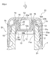
- Figs. 1 to 5 illustrate an embodiment of a container sealing device according to the present invention.
- An illustrated sealing device 100 is constituted of an inner plug 10 locked by a mouth part 1a of a container 1 through fitting or the like, and an upper closure 20 screwed with the mouth part 1a of the container 1 so as to cover an extraction port 10a of the inner plug 10.
- the inner plug 10 is an integrally molded produce made of a resin and is provided with a body part 10b locked by or fixed to the container 1 and a separation part 12.
- the body part 10b of the inner plug 10 forms the extraction port 10a of a content of the container 1 and has a cylindrical base part 11a which is a cylindrical member extending along an axial center AX, a flange part 11b extending outward in a radial direction from an outer peripheral surface of an intermediate part of the cylindrical base part 11a, and an annular wall part 11c which is an annular member extending downward from an outer end of the flange part 11b.
- These cylindrical base part 11a, the flange part 11b, and the annular wall part 11c define an annular recess part 13 fitted with the mouth part 1a of the container 1.
- a lip part 14 extending outward is formed at an upper end of the cylindrical base part 11a.
- the separation part 12 of the inner plug 10 is provided with a disc-shaped sealing body 12s arranged on a bottom part and a cylindrically-shaped cylindrical part 16 extending upward from an outer edge of this sealing body 12s.
- An outer-periphery side boundary part between the outer edge of this sealing body 12s and a lower end part of the cylindrical part 16 is connected to the body part 10b of the inner plug 10 by an annular connection part 15.
- An annular notch 18 is formed on a lower surface of the connection part 15. This notch 18 serves as a part of a score 15a cut off when opening the plug.
- a cross-shaped protrusion part 12p is provided on the lower surface side of the sealing body 12s, in order to facilitate screwing of the inner plug 10 into the upper closure 20 by rotating the inner plug 10 including the separation part 12 when the inner plug 10 is assembled to the upper closure 20.
- the cylindrical part 16 is arranged concentrically and separately inside the cylindrical base part 11a on an outer side. There is formed a female thread 17 to be screwed with a male thread 22 provided on a small-diameter cylinder part 20d of the upper closure 20 which will be described later, on an inner peripheral surface of the cylindrical part 16.
- the upper closure 20 is an integrally molded product made of a resin and is provided with a cylindrical peripheral wall part 20a which forms an appearance; and a large-diameter cylinder part (second inner cylinder part) 20b, a middle-diameter cylinder part 20c, and the small-diameter cylinder part (first inner cylinder part) 20d concentrically with the peripheral wall part 20a therein, and they are continuously provided by a ceiling wall 20e.
- a female thread 21 screwed with a male thread 2 formed on the outer peripheral side surface of the mouth part 1a of the container 1 is formed on an inner peripheral surface of the peripheral wall part 20a
- the male thread 22 screwed with the female thread 17 formed on the inner peripheral side surface of the cylindrical part 16 of the separation part 12 provided on the inner plug 10 is formed on an outer peripheral surface of the small-diameter cylinder part (first inner cylinder part) 20d.
- the male thread 21 of the peripheral wall part 20a of the upper closure 20 and the male thread 2 of the mouth part 1a of the container 1 constitute a first screwing part 51 which enables attachment and detachment of the upper closure 20 with respect to the container 1.
- the female thread 17 of the cylindrical part 16 of the inner plug 10 and the male thread 22 of the small-diameter cylinder part (first inner cylinder part) 20d of the upper closure 20 constitute a second screwing part 52 for tightening and fixing the separation part 12 of the inner plug 10 to the small-diameter cylinder part 20d of the upper closure 20.
- the small-diameter cylinder part 20d of the upper closure 20 functions as a support part for catching the separation part 12 by the second screwing part 52 and separating the separation part 12 from the inner plug 10.
- the first screwing part 51 and the second screwing part 52 are in a mutually reverse thread relation. Namely, when the first screwing part 51 is screwed back so as to be loosened by rotating the peripheral wall part 20a of the upper closure 20 in a counterclockwise direction when seen from an upper side, the small-diameter cylinder part (support part) 20d of the upper closure 20 is rotated in a counterclockwise direction when seen from the upper side, and the second screwing part 52 is tightened.
- the screwing direction or the like of the second screwing part 52 will be described in detail.
- the upper side along the axial center AX is the screwing direction for screwing with the small-diameter cylinder part 20d of the upper closure 20 by rotation in the counterclockwise direction when seen from a lower side
- a lower side along the axial center AX is the anti-screwing direction for screwing back the small-diameter cylinder part 20d by rotation in the clockwise direction.
- the lower side along the axial center AX is the screwing direction for screwing with the cylindrical part 16 by rotation in the counterclockwise direction when seen from the upper side
- the upper side along the axial center AX is the anti-screwing direction for screwing back the cylindrical part 16 by rotation in the clockwise direction when seen from the upper side.
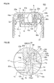
- a tip end part 16t of the cylindrical part 16 of the inner plug 10 is brought into contact with a lower surface 20t of the ceiling wall 20e of the upper closure 20 exposed between the base part of the middle-diameter cylinder part 20c and the base part of the small-diameter cylinder part 20d of the upper closure 20.
- a tip end part 20u of the small-diameter cylinder part 20d of the upper closure 20 is brought into contact with an inner-surface corner part 12u of the separation part 12 of the inner plug 10.
- the tip end part 16t of the cylindrical part 16 and the tip end part 20u of the small-diameter cylinder part 20d function as first stoppers for regulating their mutual assembling interval between the separation part 12 of the inner plug 10 and the upper closure 20. Furthermore, a tip end part 20v of the large-diameter cylinder part 20b of the upper closure 20 is in contact with an upper surface 11v of the flange part 11b of the inner plug 10. The tip end part 20v of the large-diameter cylinder part 20b functions as a second stopper regulating their mutual assembling interval between the upper closure 20 and the body part 10b of the inner plug 10.
- an outer peripheral surface 20g of the middle-diameter cylinder part 20c provided at the upper closure 20 and an inner side surface 11g of a tip end part 11w provided at the cylindrical base part 11a of the inner plug 10 are in close contact with each other. As a result, when sealing after opening the plug, the inside of the container 1 can be kept liquid-tight.
- the inner plug 10 and the upper closure 20 constituted as described above are screwed with each other by engaging the female thread 17 which is a reverse thread of the inner plug 10 with the male thread 22 which is a reverse thread of the upper closure 20, and by rotating the inner plug 10 in a counterclockwise direction when seen from the inner plug 10 side or by rotating the upper closure 20 in the counterclockwise direction when seen from the upper closure 20 side.
- a tool can be utilized, and the protrusion part 12p of the separation part 12 is supported by a chuck part of the tool.
- the upper closure 20 and the inner plug 10 are tightened to the deepest position and integrated.
- the small-diameter cylinder part (first inner cylinder part) 20d of the upper closure 20 is fitted so as to be pushed into the inner plug 10 until the tip end part 16t of the cylindrical part 16 reaches a state of being brought into contact with the lower surface 20t of the ceiling wall 20e of the upper closure 20 or is screwed into the inner plug 10 until the tip end part 20u of the small-diameter cylinder part 20d reaches a state of being brought into contact with the inner-surface corner part 12u of the separation part 12 of the inner plug 10.
- the tip end part 20v of the large-diameter cylinder part (second inner cylinder part) 20b of the upper closure 20 is brought into contact with the upper surface 11v of the flange part 11b of the inner plug 10.
- the interval between the inner plug 10 and the upper closure 20 is adjusted, and as illustrated in Figs. 3B and the like, the tip end part 16t of the cylindrical part 16 is accommodated in a recess part 23 formed at a base part between the middle-diameter cylinder part 20c and the small-diameter cylinder part 20d.
- the lip part 14 formed at the tip end of the cylindrical base part 11a is positioned in a state of being brought into contact with the lower surface 20t of the ceiling wall 20e of the upper closure 20.
- the cap an assembly of the inner plug 10 and the upper closure 20 assembled as described above is locked by the container 1 by fitting the annular recess part 13 defined by the cylindrical base part 11a of the inner plug 10, the flange part 11b and the annular wall part 11c, with the mouth part 1a of the container 1, as illustrated in Fig. 4 .
- the upper closure 20 is screwed with the mouth part 1a of the container 1, and the body part 10b of the inner plug 10 reaches a state of being fitted air-tightly with the mouth part 1a.
- the female thread 21 with a forward thread formed on the peripheral wall part 20a of the upper closure 20 is engaged with the male thread 2 with a forward thread formed on the mouth part 1a of the container 1, and, for example, the upper closure 20 is rotated in a clockwise direction when seen from the upper closure 20 side or the container 1 is rotated in the clockwise direction when seen from the container 1 side, whereby the both are screwed with each other.
- the annular wall part 11c and the like ride over a tip end 1b of the mouth part 1a of the container 1, the inner plug 10 is subjected to an action of screwing back by receiving a torque of a left thread.
- the inner plug 10 is pressed into the upper closure 20 by the mouth part 1a of the container 1, and the inner plug 10 is substantially fixed to the upper closure 20 and is hardly screwed back due to an influence of friction between the upper closure 20 and the inner plug 10 and the like. Furthermore, displacement of the body part 10b of the inner plug 10 is prevented by the tip end part 20v of the large-diameter cylinder part 20b which is the second stopper, and a relatively large load or stress is prevented from being applied to the separation part 12 via the body part 10b.
- the cap the assembly of the inner plug 10 and the upper closure 20
- the assembly of the inner plug 10 and the upper closure 20 can also be capped (forcedly pushed in and fixed) instead of being screwed into the mouth part 1a.
- the tip end part 20v of the large-diameter cylinder part 20b which is the second stopper
- large displacement of the body part 10b of the inner plug 10 with respect to the upper closure 20 can be avoided in capping, and damage can be prevented from being caused in the periphery of the separation part 12, by application of a relatively large load or stress to the separation part 12 via the body part.
- the upper closure 20 is at an initial position (a state of being screwed into the deepest position or close to that) before a rotating operation of the screwing part, while the separation part 12 and the cylindrical part 16 are in a connected state, that is, in a state where the score 15a of the connection part 15 is not cut off, and thus an opening part 3 of the container 1 is in a sealed state.
- the upper closure 20 is moved upward by rotating the upper closure 20 in a loosening direction, that is, in a counterclockwise direction.
- the separation part 12 is subjected to an action of moving upward with respect to the upper closure 20.
- the separation part 12 is screwed with the upper closure 20 through reverse threads substantially to the deepest position, further tightening is not performed or tightening somewhat progresses and enters a lock state where movement to the direction of the upper closure 20 is prevented. Namely, the separation part 12 is moved upward together with the upper closure 20 while rotating in the counterclockwise direction when seen from above with respect to the body part 10b.
- connection part 15 since a stress concentrates on the notch 18 or the score 15a of the inner plug 10, the connection part 15 is sheared, the separation part 12 is removed from the cylindrical base part 11a and the plug is opened.
- the separation part 12 since the separation part 12 is elevated together with the upper closure 20 while rotating, a clear opening feeling can be generated when the separation part 12 is separated from the cylindrical base part 11a by breakage of the score 15a. Namely, a snap sound is generated in the opening of the plug, and a torque required for rotation of the upper closure 20 is rapidly reduced.
- the upper closure 20 separates from the cylindrical base part 11a by rotating the upper closure 20 in the loosening direction, as illustrated in Fig. 5 , whereby the contents in the container 1 can be poured.
- the separation part 12 is ensured by the upper closure 20 and is in a lock state with respect to the upper closure 20, and thus there is no risk of removal. Namely, once being opened, the separation part 12 fixed to the inner plug 10 side is fixed to the upper closure 20 side.
- the inner plug 10 is assembled to the upper closure 20 by using the second screwing part 52 in advance.
- the second screwing part 52 can be brought into a lock state of being screwed to the deepest position or a state close to that.
- the first screwing part 51 is loosened by rotating the upper closure 20 so as to be screwed back, but along with that, the second screwing part 52 which has been already substantially locked is tightened, and the separation part 12 can be rapidly and reliably separated from the body part 10b of the inner plug 10.
- the separation part 12 becomes less likely to be removed from the upper closure 20, and is reliably held.
- a clear opening feeling such as generation of a snap sound or sudden reduction in resistance against rotation can be presented by separating the separation part 12 from the body part 10b of the inner plug 10 while tightening the second screwing part 52 which has been substantially locked.
- the container sealing device according to the present embodiment has been described, but the container sealing device according to the present invention is not limited to the above.
- specifications such as a pitch, a winding number, a thread height and the like of the male thread 2 and the female thread 21 constituting the first screwing part 51 can be appropriately modified in accordance with application.
- the specifications such as a pitch, a winding number, a thread height and the like of the male thread 22 and the female thread 17 constituting the second screwing part 52 can also be appropriately modified in accordance with application.
- the cylindrical part 16 of the inner plug 10 and the small-diameter cylinder part 20d of the upper closure 20 can be switched inside and outside. Also in this case, the male thread of the cylindrical part 16 and the female thread of the small-diameter cylinder part 20d constitute the second screwing part 52 in the reverse thread relation with respect to the first screwing part 51.
- the tip end part 20u of the small-diameter cylinder part 20d of the upper closure 20 can be spaced away from the inner-surface corner part 12u of the separation part 12.
- the tip end part 16t of the cylindrical part 16 of the inner plug 10 can be spaced away from the lower surface 20t of the ceiling wall 20e of the upper closure 20.
- the tip end part 20u on an inner side is preferably spaced away from the inner-surface corner part 12u from the viewpoint of preventing removal or the like of the separation part 12 by protecting the second screwing part 52 from the contents in the container 1.
- the female thread 17 and the male thread 22 constituting the second screwing part 52 are not limited to those formed continuously and spirally, but can be composed of a plurality of separate parts.
- the container 1 has a bottle shape of a PET bottle or the like.
- the container 1 is not limited to the bottle as described above, but can have a bag shape made of a film or can be any other polygonal paper packages.
- the inner plug 10 can have a spout shape with a flange and can be fixed to the container by fusion or the like.
- the first screwing part 51 may be provided not only between the upper closure 20 and the container 1, but also between the upper closure 20 and the inner plug 10 fixed to the container 1.
- the first screwing part 51 is provided between the upper closure 20 and the inner plug 10
- at least either one of the first screwing part 51 and the second screwing part 52 is forcedly pushed in and fitted, in assembling. Therefore, it is possible to facilitate mounting of the inner plug 10 to the upper closure 20 by, for example, forming the thread of the first screwing part 51 or the second screwing part 52 into a shape that can be easily pushed in.
Landscapes
- Engineering & Computer Science (AREA)
- Mechanical Engineering (AREA)
- Closures For Containers (AREA)
Applications Claiming Priority (2)
| Application Number | Priority Date | Filing Date | Title |
|---|---|---|---|
| JP2013012712 | 2013-01-25 | ||
| PCT/JP2014/051577 WO2014115856A1 (fr) | 2013-01-25 | 2014-01-24 | Dispositif de scellage de contenants |
Publications (3)
| Publication Number | Publication Date |
|---|---|
| EP2949596A1 true EP2949596A1 (fr) | 2015-12-02 |
| EP2949596A4 EP2949596A4 (fr) | 2016-09-14 |
| EP2949596B1 EP2949596B1 (fr) | 2018-01-03 |
Family
ID=51227645
Family Applications (1)
| Application Number | Title | Priority Date | Filing Date |
|---|---|---|---|
| EP14743921.0A Active EP2949596B1 (fr) | 2013-01-25 | 2014-01-24 | Dispositif de fermeture de contenants |
Country Status (6)
| Country | Link |
|---|---|
| US (1) | US10086980B2 (fr) |
| EP (1) | EP2949596B1 (fr) |
| JP (1) | JP6231996B2 (fr) |
| KR (1) | KR20150112948A (fr) |
| CN (1) | CN105073596B (fr) |
| WO (1) | WO2014115856A1 (fr) |
Families Citing this family (35)
| Publication number | Priority date | Publication date | Assignee | Title |
|---|---|---|---|---|
| EP2949595B1 (fr) * | 2013-01-25 | 2018-08-01 | Tokan Kogyo Co., Ltd. | Dispositif de scellage de contenants |
| US10086980B2 (en) * | 2013-01-25 | 2018-10-02 | Tokan Kogyo Co., Ltd. | Container sealing device |
| US10029832B2 (en) * | 2013-12-06 | 2018-07-24 | Tokan Kogyo Co., Ltd. | Container sealing device |
| US11317647B2 (en) * | 2014-12-02 | 2022-05-03 | Monarch Media, Llc | Coconut water removal device and method therefor |
| US20160345619A1 (en) * | 2014-12-02 | 2016-12-01 | Monarch Media Llc. | Coconut removal device and method therefor |
| JP6355553B2 (ja) * | 2014-12-25 | 2018-07-11 | 株式会社吉野工業所 | 容器 |
| US10093460B2 (en) | 2015-08-14 | 2018-10-09 | Yeti Coolers, Llc | Container with magnetic cap |
| USD787893S1 (en) | 2015-11-20 | 2017-05-30 | Yeti Coolers, Llc | Jug |
| EP3411303B1 (fr) * | 2016-02-01 | 2021-04-21 | Société des Produits Nestlé S.A. | Ensemble capuchon de fermeture |
| WO2017209756A1 (fr) * | 2016-06-02 | 2017-12-07 | Silgan White Cap LLC | Dispositif de fermeture avec garniture |
| JP6835515B2 (ja) * | 2016-09-26 | 2021-02-24 | 東罐興業株式会社 | 容器の封止装置 |
| US11034505B2 (en) | 2016-10-17 | 2021-06-15 | Yeti Coolers, Llc | Container and method of forming a container |
| EP3525638B1 (fr) | 2016-10-17 | 2021-11-17 | YETI Coolers, LLC | Contenant isotherme avec couvercle magnétique |
| US10959553B2 (en) | 2016-10-17 | 2021-03-30 | Yeti Coolers, Llc | Container and method of forming a container |
| CN108357778B (zh) * | 2017-01-26 | 2021-12-28 | 本诺瓦公司 | 将产品分配在容器中的盒 |
| JP6894728B2 (ja) * | 2017-03-15 | 2021-06-30 | 日本クロージャー株式会社 | 複合容器蓋 |
| USD860716S1 (en) | 2017-03-27 | 2019-09-24 | Yeti Coolers, Llc | Container lid |
| KR102583427B1 (ko) * | 2017-06-30 | 2023-09-26 | 니혼 클로져 가부시키가이샤 | 플라스틱 캡 및 그 제조 방법 |
| JP2020533242A (ja) * | 2017-09-11 | 2020-11-19 | リクイ−ボックス コーポレイション | 無菌スクリュ−キャップアセンブリ |
| US10258710B1 (en) * | 2017-09-22 | 2019-04-16 | S. C. Johnson & Son, Inc. | Container for holding volatile materials |
| JP7055623B2 (ja) * | 2017-11-30 | 2022-04-18 | 株式会社吉野工業所 | ねじキャップ |
| CN108891758A (zh) * | 2018-03-24 | 2018-11-27 | 中山市华宝勒生活用品实业有限公司 | 一种螺旋盖 |
| USD896572S1 (en) | 2018-08-20 | 2020-09-22 | Yeti Coolers, Llc | Container lid |
| USD883738S1 (en) | 2018-10-17 | 2020-05-12 | Yeti Coolers, Llc | Lid |
| USD883737S1 (en) | 2018-10-17 | 2020-05-12 | Yeti Coolers, Llc | Lid |
| USD871133S1 (en) | 2018-10-17 | 2019-12-31 | Yeti Coolers, Llc | Lid |
| USD897151S1 (en) | 2018-10-17 | 2020-09-29 | Yeti Coolers, Llc | Lid |
| WO2020239834A2 (fr) * | 2019-05-27 | 2020-12-03 | Rpc Bramlage Gmbh | Dispositif de fermeture conçu pour un contenant |
| EP4103489A4 (fr) * | 2020-02-10 | 2024-05-15 | Eco.logic Brands Inc. | Récipient modulaire à performances améliorées |
| EP4255821B1 (fr) * | 2020-12-03 | 2025-08-27 | Runway Blue, LLC | Récipient à boire avec dispositif de fermeture |
| MX2024012866A (es) * | 2022-04-20 | 2024-12-06 | Origin Mat Operating Inc | Cierres de resina de poliéster para recipientes |
| US20240262585A1 (en) * | 2023-02-08 | 2024-08-08 | Yonghui Fang | Dispenser |
| IT202300002118A1 (it) * | 2023-02-08 | 2024-08-08 | Capardoni & C S R L | Sistema di chiusura |
| US12589919B2 (en) | 2023-06-07 | 2026-03-31 | Yeti Coolers, Llc | Lid assembly for beverage container |
| US12428208B1 (en) * | 2023-08-14 | 2025-09-30 | Shailendra Joshi | Beverage container having dry ingredient storage for mixing thereof |
Family Cites Families (29)
| Publication number | Priority date | Publication date | Assignee | Title |
|---|---|---|---|---|
| JPS5244953B2 (fr) | 1974-02-16 | 1977-11-11 | ||
| JPS5520603Y2 (fr) * | 1974-09-04 | 1980-05-17 | ||
| NL7413077A (nl) * | 1974-10-03 | 1976-04-06 | Leer Koninklijke Emballage | Houder met schroefdop. |
| FR2342914A1 (fr) * | 1976-03-02 | 1977-09-30 | Oreal | Dispositif de conditionnement de deux produits isoles l'un de l'autre avant la distribution |
| FR2407141A1 (fr) | 1977-10-28 | 1979-05-25 | Cebal | Dispositif d'inviolabilite pour recipient dont le goulot est ferme par une capsule vissee |
| DE3426739A1 (de) * | 1984-07-20 | 1986-01-30 | Robert Finke KG, 5950 Finnentrop | Zwei-komponenten-packung |
| DE8502008U1 (de) * | 1985-01-26 | 1985-08-29 | Celamerck Gmbh & Co Kg, 6507 Ingelheim | Verschlußkappe für Zweikomponentenpackungen |
| FR2609970B1 (fr) | 1987-01-23 | 1990-02-23 | Moulage Specialise Pack Atel | Dispositif de fermeture d'un recipient a col a elements de positionnement elastiquement deformables |
| AT398954B (de) | 1988-08-18 | 1995-02-27 | Greiter Ag | Tube |
| JPH0319879U (fr) * | 1989-07-05 | 1991-02-27 | ||
| FR2720377B1 (fr) * | 1994-05-24 | 1996-08-23 | Rical Sa | Bouchon-verseur à opercule d'inviolabilité. |
| FR2770832B1 (fr) * | 1997-11-10 | 1999-12-10 | Lorraine Capsules Metall | Dispositif de bouchage d'un emballage pourvu d'une ouverture predecoupee et obturee par une pastille de securite |
| BR9908012A (pt) | 1998-02-17 | 2000-10-24 | Elopak As | Guarnição de bico de despejar, combinação de material de embalagem e uma guarnição de bico de despejar, e, processo para fornecer um material de embalagem |
| JP4160163B2 (ja) * | 1998-06-11 | 2008-10-01 | 日本テトラパック株式会社 | キャップ付き容器 |
| KR100553806B1 (ko) * | 2002-09-27 | 2006-02-22 | 가부시키가이샤 니프코 | 병형상을 이루는 용기의 캡 |
| EP1752381A1 (fr) * | 2005-08-12 | 2007-02-14 | Obrist Closures Switzerland GmbH | Bouchon |
| US7588142B1 (en) * | 2005-11-18 | 2009-09-15 | Rexam Closures And Containers Inc. | Additive delivery system closure |
| KR101258382B1 (ko) * | 2006-04-28 | 2013-05-07 | 도칸 고교 가부시키가이샤 | 캡 및 뚜껑 부착 용기 |
| MX2011003713A (es) * | 2008-10-08 | 2011-07-28 | Sanner Friedr Gmbh Co Kg | Cierre para atornillado en recipiente. |
| IT1394565B1 (it) | 2009-06-23 | 2012-07-05 | Silvia Ferrari | Tappo a vite per recipienti contenenti prodotti liquidi |
| DE102010028522A1 (de) * | 2010-05-04 | 2011-11-10 | Robert Bosch Gmbh | Schraubverschluss für Weichverpackungen |
| DE102010048415A1 (de) * | 2010-10-15 | 2012-04-19 | Sig Technology Ag | Wiederverschließbares Ausgießelement mit Barrierefolie und Stützwand |
| FR3000036B1 (fr) * | 2012-12-26 | 2015-02-20 | Albea Services | Tete de tube munie d'un opercule, associee a un bouchon perforateur ameliore assurant la preservation de l'opercule prealablement a sa premiere utilisation |
| US10086980B2 (en) * | 2013-01-25 | 2018-10-02 | Tokan Kogyo Co., Ltd. | Container sealing device |
| EP2949595B1 (fr) * | 2013-01-25 | 2018-08-01 | Tokan Kogyo Co., Ltd. | Dispositif de scellage de contenants |
| KR20150143815A (ko) * | 2013-07-12 | 2015-12-23 | 도칸 고교 가부시키가이샤 | 캡 조립체 및 그 타전 방법 |
| WO2015004800A1 (fr) * | 2013-07-12 | 2015-01-15 | 東罐興業株式会社 | Ensemble capuchon et son procédé d'assemblage |
| US10029832B2 (en) * | 2013-12-06 | 2018-07-24 | Tokan Kogyo Co., Ltd. | Container sealing device |
| KR102482736B1 (ko) * | 2014-07-30 | 2022-12-30 | 도판 인사츠 가부시키가이샤 | 주출구 마개 및 포장 용기 |
-
2014
- 2014-01-24 US US14/762,417 patent/US10086980B2/en active Active
- 2014-01-24 CN CN201480006070.6A patent/CN105073596B/zh active Active
- 2014-01-24 EP EP14743921.0A patent/EP2949596B1/fr active Active
- 2014-01-24 KR KR1020157018864A patent/KR20150112948A/ko not_active Ceased
- 2014-01-24 WO PCT/JP2014/051577 patent/WO2014115856A1/fr not_active Ceased
- 2014-01-24 JP JP2014558636A patent/JP6231996B2/ja active Active
Also Published As
| Publication number | Publication date |
|---|---|
| JP6231996B2 (ja) | 2017-11-15 |
| US10086980B2 (en) | 2018-10-02 |
| CN105073596A (zh) | 2015-11-18 |
| US20150321798A1 (en) | 2015-11-12 |
| EP2949596B1 (fr) | 2018-01-03 |
| CN105073596B (zh) | 2017-08-25 |
| JPWO2014115856A1 (ja) | 2017-01-26 |
| KR20150112948A (ko) | 2015-10-07 |
| WO2014115856A1 (fr) | 2014-07-31 |
| EP2949596A4 (fr) | 2016-09-14 |
Similar Documents
| Publication | Publication Date | Title |
|---|---|---|
| EP2949596B1 (fr) | Dispositif de fermeture de contenants | |
| EP2949595B1 (fr) | Dispositif de scellage de contenants | |
| US9862528B2 (en) | Cap assembly and method for capping same | |
| CN105992742B (zh) | 容器的密封装置 | |
| EP3303165B1 (fr) | Fermeture inviolable | |
| US20160068316A1 (en) | Welded part with barrier layer | |
| JP2014019447A (ja) | 口栓 | |
| KR101775809B1 (ko) | 캡 조립체 및 그 조립 방법 | |
| JP5757568B2 (ja) | 容器蓋 | |
| JP2013147265A (ja) | キャップ組立体およびその打栓方法 | |
| JP6835515B2 (ja) | 容器の封止装置 | |
| WO2018168523A1 (fr) | Couvercle de récipient composite | |
| JP2011162215A (ja) | キャップ付容器 | |
| JP6702020B2 (ja) | キャップ構造体及びこれを用いた包装容器 | |
| JP6971172B2 (ja) | 注出容器 | |
| JP4470155B2 (ja) | キャップ付き口栓のタンパーエビデンス構造 | |
| JP5829579B2 (ja) | 不正開封を検知できる開口部保護構造を備えた容器 | |
| JP2014177288A (ja) | 容器用キャップおよび該容器用キャップを備えたキャップ付き容器 | |
| JP2026001305A (ja) | 合成樹脂製キャップ | |
| JP2024025150A (ja) | 開封構造及びこれを用いた包装容器 | |
| JP5851348B2 (ja) | 吐出容器 | |
| JP2013203465A (ja) | キャップ | |
| JP2017226460A (ja) | キャップ構造体及びこれを用いた包装容器 |
Legal Events
| Date | Code | Title | Description |
|---|---|---|---|
| PUAI | Public reference made under article 153(3) epc to a published international application that has entered the european phase |
Free format text: ORIGINAL CODE: 0009012 |
|
| 17P | Request for examination filed |
Effective date: 20150805 |
|
| AK | Designated contracting states |
Kind code of ref document: A1 Designated state(s): AL AT BE BG CH CY CZ DE DK EE ES FI FR GB GR HR HU IE IS IT LI LT LU LV MC MK MT NL NO PL PT RO RS SE SI SK SM TR |
|
| AX | Request for extension of the european patent |
Extension state: BA ME |
|
| DAX | Request for extension of the european patent (deleted) | ||
| A4 | Supplementary search report drawn up and despatched |
Effective date: 20160817 |
|
| RIC1 | Information provided on ipc code assigned before grant |
Ipc: B65D 47/10 20060101ALI20160810BHEP Ipc: B65D 51/22 20060101AFI20160810BHEP Ipc: B65D 47/12 20060101ALI20160810BHEP |
|
| GRAP | Despatch of communication of intention to grant a patent |
Free format text: ORIGINAL CODE: EPIDOSNIGR1 |
|
| INTG | Intention to grant announced |
Effective date: 20170707 |
|
| GRAJ | Information related to disapproval of communication of intention to grant by the applicant or resumption of examination proceedings by the epo deleted |
Free format text: ORIGINAL CODE: EPIDOSDIGR1 |
|
| GRAR | Information related to intention to grant a patent recorded |
Free format text: ORIGINAL CODE: EPIDOSNIGR71 |
|
| GRAS | Grant fee paid |
Free format text: ORIGINAL CODE: EPIDOSNIGR3 |
|
| GRAA | (expected) grant |
Free format text: ORIGINAL CODE: 0009210 |
|
| INTC | Intention to grant announced (deleted) | ||
| AK | Designated contracting states |
Kind code of ref document: B1 Designated state(s): AL AT BE BG CH CY CZ DE DK EE ES FI FR GB GR HR HU IE IS IT LI LT LU LV MC MK MT NL NO PL PT RO RS SE SI SK SM TR |
|
| INTG | Intention to grant announced |
Effective date: 20171124 |
|
| REG | Reference to a national code |
Ref country code: GB Ref legal event code: FG4D |
|
| REG | Reference to a national code |
Ref country code: CH Ref legal event code: EP Ref country code: AT Ref legal event code: REF Ref document number: 960020 Country of ref document: AT Kind code of ref document: T Effective date: 20180115 |
|
| REG | Reference to a national code |
Ref country code: FR Ref legal event code: PLFP Year of fee payment: 5 |
|
| REG | Reference to a national code |
Ref country code: IE Ref legal event code: FG4D |
|
| REG | Reference to a national code |
Ref country code: DE Ref legal event code: R096 Ref document number: 602014019418 Country of ref document: DE |
|
| REG | Reference to a national code |
Ref country code: NL Ref legal event code: MP Effective date: 20180103 |
|
| REG | Reference to a national code |
Ref country code: LT Ref legal event code: MG4D |
|
| REG | Reference to a national code |
Ref country code: AT Ref legal event code: MK05 Ref document number: 960020 Country of ref document: AT Kind code of ref document: T Effective date: 20180103 |
|
| PG25 | Lapsed in a contracting state [announced via postgrant information from national office to epo] |
Ref country code: NL Free format text: LAPSE BECAUSE OF FAILURE TO SUBMIT A TRANSLATION OF THE DESCRIPTION OR TO PAY THE FEE WITHIN THE PRESCRIBED TIME-LIMIT Effective date: 20180103 |
|
| PG25 | Lapsed in a contracting state [announced via postgrant information from national office to epo] |
Ref country code: ES Free format text: LAPSE BECAUSE OF FAILURE TO SUBMIT A TRANSLATION OF THE DESCRIPTION OR TO PAY THE FEE WITHIN THE PRESCRIBED TIME-LIMIT Effective date: 20180103 Ref country code: HR Free format text: LAPSE BECAUSE OF FAILURE TO SUBMIT A TRANSLATION OF THE DESCRIPTION OR TO PAY THE FEE WITHIN THE PRESCRIBED TIME-LIMIT Effective date: 20180103 Ref country code: LT Free format text: LAPSE BECAUSE OF FAILURE TO SUBMIT A TRANSLATION OF THE DESCRIPTION OR TO PAY THE FEE WITHIN THE PRESCRIBED TIME-LIMIT Effective date: 20180103 Ref country code: NO Free format text: LAPSE BECAUSE OF FAILURE TO SUBMIT A TRANSLATION OF THE DESCRIPTION OR TO PAY THE FEE WITHIN THE PRESCRIBED TIME-LIMIT Effective date: 20180403 Ref country code: FI Free format text: LAPSE BECAUSE OF FAILURE TO SUBMIT A TRANSLATION OF THE DESCRIPTION OR TO PAY THE FEE WITHIN THE PRESCRIBED TIME-LIMIT Effective date: 20180103 Ref country code: CY Free format text: LAPSE BECAUSE OF FAILURE TO SUBMIT A TRANSLATION OF THE DESCRIPTION OR TO PAY THE FEE WITHIN THE PRESCRIBED TIME-LIMIT Effective date: 20180103 |
|
| PG25 | Lapsed in a contracting state [announced via postgrant information from national office to epo] |
Ref country code: IS Free format text: LAPSE BECAUSE OF FAILURE TO SUBMIT A TRANSLATION OF THE DESCRIPTION OR TO PAY THE FEE WITHIN THE PRESCRIBED TIME-LIMIT Effective date: 20180503 Ref country code: SE Free format text: LAPSE BECAUSE OF FAILURE TO SUBMIT A TRANSLATION OF THE DESCRIPTION OR TO PAY THE FEE WITHIN THE PRESCRIBED TIME-LIMIT Effective date: 20180103 Ref country code: LV Free format text: LAPSE BECAUSE OF FAILURE TO SUBMIT A TRANSLATION OF THE DESCRIPTION OR TO PAY THE FEE WITHIN THE PRESCRIBED TIME-LIMIT Effective date: 20180103 Ref country code: PL Free format text: LAPSE BECAUSE OF FAILURE TO SUBMIT A TRANSLATION OF THE DESCRIPTION OR TO PAY THE FEE WITHIN THE PRESCRIBED TIME-LIMIT Effective date: 20180103 Ref country code: GR Free format text: LAPSE BECAUSE OF FAILURE TO SUBMIT A TRANSLATION OF THE DESCRIPTION OR TO PAY THE FEE WITHIN THE PRESCRIBED TIME-LIMIT Effective date: 20180404 Ref country code: AT Free format text: LAPSE BECAUSE OF FAILURE TO SUBMIT A TRANSLATION OF THE DESCRIPTION OR TO PAY THE FEE WITHIN THE PRESCRIBED TIME-LIMIT Effective date: 20180103 Ref country code: RS Free format text: LAPSE BECAUSE OF FAILURE TO SUBMIT A TRANSLATION OF THE DESCRIPTION OR TO PAY THE FEE WITHIN THE PRESCRIBED TIME-LIMIT Effective date: 20180103 Ref country code: BG Free format text: LAPSE BECAUSE OF FAILURE TO SUBMIT A TRANSLATION OF THE DESCRIPTION OR TO PAY THE FEE WITHIN THE PRESCRIBED TIME-LIMIT Effective date: 20180403 |
|
| REG | Reference to a national code |
Ref country code: CH Ref legal event code: PL |
|
| REG | Reference to a national code |
Ref country code: DE Ref legal event code: R097 Ref document number: 602014019418 Country of ref document: DE |
|
| PG25 | Lapsed in a contracting state [announced via postgrant information from national office to epo] |
Ref country code: IT Free format text: LAPSE BECAUSE OF FAILURE TO SUBMIT A TRANSLATION OF THE DESCRIPTION OR TO PAY THE FEE WITHIN THE PRESCRIBED TIME-LIMIT Effective date: 20180103 Ref country code: MC Free format text: LAPSE BECAUSE OF FAILURE TO SUBMIT A TRANSLATION OF THE DESCRIPTION OR TO PAY THE FEE WITHIN THE PRESCRIBED TIME-LIMIT Effective date: 20180103 Ref country code: AL Free format text: LAPSE BECAUSE OF FAILURE TO SUBMIT A TRANSLATION OF THE DESCRIPTION OR TO PAY THE FEE WITHIN THE PRESCRIBED TIME-LIMIT Effective date: 20180103 Ref country code: LU Free format text: LAPSE BECAUSE OF NON-PAYMENT OF DUE FEES Effective date: 20180124 Ref country code: EE Free format text: LAPSE BECAUSE OF FAILURE TO SUBMIT A TRANSLATION OF THE DESCRIPTION OR TO PAY THE FEE WITHIN THE PRESCRIBED TIME-LIMIT Effective date: 20180103 Ref country code: RO Free format text: LAPSE BECAUSE OF FAILURE TO SUBMIT A TRANSLATION OF THE DESCRIPTION OR TO PAY THE FEE WITHIN THE PRESCRIBED TIME-LIMIT Effective date: 20180103 |
|
| REG | Reference to a national code |
Ref country code: IE Ref legal event code: MM4A |
|
| REG | Reference to a national code |
Ref country code: BE Ref legal event code: MM Effective date: 20180131 |
|
| PLBE | No opposition filed within time limit |
Free format text: ORIGINAL CODE: 0009261 |
|
| STAA | Information on the status of an ep patent application or granted ep patent |
Free format text: STATUS: NO OPPOSITION FILED WITHIN TIME LIMIT |
|
| PG25 | Lapsed in a contracting state [announced via postgrant information from national office to epo] |
Ref country code: DK Free format text: LAPSE BECAUSE OF FAILURE TO SUBMIT A TRANSLATION OF THE DESCRIPTION OR TO PAY THE FEE WITHIN THE PRESCRIBED TIME-LIMIT Effective date: 20180103 Ref country code: CH Free format text: LAPSE BECAUSE OF NON-PAYMENT OF DUE FEES Effective date: 20180131 Ref country code: SM Free format text: LAPSE BECAUSE OF FAILURE TO SUBMIT A TRANSLATION OF THE DESCRIPTION OR TO PAY THE FEE WITHIN THE PRESCRIBED TIME-LIMIT Effective date: 20180103 Ref country code: LI Free format text: LAPSE BECAUSE OF NON-PAYMENT OF DUE FEES Effective date: 20180131 Ref country code: CZ Free format text: LAPSE BECAUSE OF FAILURE TO SUBMIT A TRANSLATION OF THE DESCRIPTION OR TO PAY THE FEE WITHIN THE PRESCRIBED TIME-LIMIT Effective date: 20180103 Ref country code: BE Free format text: LAPSE BECAUSE OF NON-PAYMENT OF DUE FEES Effective date: 20180131 Ref country code: SK Free format text: LAPSE BECAUSE OF FAILURE TO SUBMIT A TRANSLATION OF THE DESCRIPTION OR TO PAY THE FEE WITHIN THE PRESCRIBED TIME-LIMIT Effective date: 20180103 |
|
| 26N | No opposition filed |
Effective date: 20181005 |
|
| PG25 | Lapsed in a contracting state [announced via postgrant information from national office to epo] |
Ref country code: IE Free format text: LAPSE BECAUSE OF NON-PAYMENT OF DUE FEES Effective date: 20180124 |
|
| PG25 | Lapsed in a contracting state [announced via postgrant information from national office to epo] |
Ref country code: SI Free format text: LAPSE BECAUSE OF FAILURE TO SUBMIT A TRANSLATION OF THE DESCRIPTION OR TO PAY THE FEE WITHIN THE PRESCRIBED TIME-LIMIT Effective date: 20180103 |
|
| PG25 | Lapsed in a contracting state [announced via postgrant information from national office to epo] |
Ref country code: MT Free format text: LAPSE BECAUSE OF NON-PAYMENT OF DUE FEES Effective date: 20180124 |
|
| PG25 | Lapsed in a contracting state [announced via postgrant information from national office to epo] |
Ref country code: TR Free format text: LAPSE BECAUSE OF FAILURE TO SUBMIT A TRANSLATION OF THE DESCRIPTION OR TO PAY THE FEE WITHIN THE PRESCRIBED TIME-LIMIT Effective date: 20180103 |
|
| PG25 | Lapsed in a contracting state [announced via postgrant information from national office to epo] |
Ref country code: PT Free format text: LAPSE BECAUSE OF FAILURE TO SUBMIT A TRANSLATION OF THE DESCRIPTION OR TO PAY THE FEE WITHIN THE PRESCRIBED TIME-LIMIT Effective date: 20180103 |
|
| PG25 | Lapsed in a contracting state [announced via postgrant information from national office to epo] |
Ref country code: MK Free format text: LAPSE BECAUSE OF NON-PAYMENT OF DUE FEES Effective date: 20180103 Ref country code: HU Free format text: LAPSE BECAUSE OF FAILURE TO SUBMIT A TRANSLATION OF THE DESCRIPTION OR TO PAY THE FEE WITHIN THE PRESCRIBED TIME-LIMIT; INVALID AB INITIO Effective date: 20140124 |
|
| REG | Reference to a national code |
Ref country code: DE Ref legal event code: R082 Ref document number: 602014019418 Country of ref document: DE Representative=s name: KILIAN KILIAN & PARTNER MBB PATENTANWAELTE, DE |
|
| PGFP | Annual fee paid to national office [announced via postgrant information from national office to epo] |
Ref country code: DE Payment date: 20250121 Year of fee payment: 12 |
|
| PGFP | Annual fee paid to national office [announced via postgrant information from national office to epo] |
Ref country code: FR Payment date: 20250127 Year of fee payment: 12 |
|
| PGFP | Annual fee paid to national office [announced via postgrant information from national office to epo] |
Ref country code: GB Payment date: 20250128 Year of fee payment: 12 |