EP2949629A1 - Wasserbehandlungssystem - Google Patents
Wasserbehandlungssystem Download PDFInfo
- Publication number
- EP2949629A1 EP2949629A1 EP13882298.6A EP13882298A EP2949629A1 EP 2949629 A1 EP2949629 A1 EP 2949629A1 EP 13882298 A EP13882298 A EP 13882298A EP 2949629 A1 EP2949629 A1 EP 2949629A1
- Authority
- EP
- European Patent Office
- Prior art keywords
- unit
- water
- ions
- ion
- deionization
- Prior art date
- Legal status (The legal status is an assumption and is not a legal conclusion. Google has not performed a legal analysis and makes no representation as to the accuracy of the status listed.)
- Withdrawn
Links
- XLYOFNOQVPJJNP-UHFFFAOYSA-N water Substances O XLYOFNOQVPJJNP-UHFFFAOYSA-N 0.000 title claims abstract description 404
- 150000002500 ions Chemical class 0.000 claims abstract description 379
- 238000002242 deionisation method Methods 0.000 claims abstract description 159
- 238000011144 upstream manufacturing Methods 0.000 claims abstract description 40
- 238000000034 method Methods 0.000 claims abstract description 30
- 230000008929 regeneration Effects 0.000 claims abstract description 15
- 238000011069 regeneration method Methods 0.000 claims abstract description 15
- 239000003014 ion exchange membrane Substances 0.000 claims abstract description 4
- 238000001556 precipitation Methods 0.000 claims description 61
- 238000000926 separation method Methods 0.000 claims description 29
- 239000007787 solid Substances 0.000 claims description 26
- 239000007788 liquid Substances 0.000 claims description 22
- 239000006228 supernatant Substances 0.000 claims description 22
- 238000001816 cooling Methods 0.000 claims description 17
- 230000018044 dehydration Effects 0.000 claims description 12
- 238000006297 dehydration reaction Methods 0.000 claims description 12
- 239000002244 precipitate Substances 0.000 claims description 5
- 239000012141 concentrate Substances 0.000 claims description 4
- 150000008044 alkali metal hydroxides Chemical class 0.000 claims description 2
- 238000007599 discharging Methods 0.000 description 44
- 238000010276 construction Methods 0.000 description 40
- VYPSYNLAJGMNEJ-UHFFFAOYSA-N silicon dioxide Inorganic materials O=[Si]=O VYPSYNLAJGMNEJ-UHFFFAOYSA-N 0.000 description 37
- 239000012528 membrane Substances 0.000 description 31
- 238000001223 reverse osmosis Methods 0.000 description 27
- VTYYLEPIZMXCLO-UHFFFAOYSA-L Calcium carbonate Chemical compound [Ca+2].[O-]C([O-])=O VTYYLEPIZMXCLO-UHFFFAOYSA-L 0.000 description 22
- 239000000377 silicon dioxide Substances 0.000 description 19
- 238000004519 manufacturing process Methods 0.000 description 16
- 239000000126 substance Substances 0.000 description 13
- 229910000019 calcium carbonate Inorganic materials 0.000 description 11
- BVKZGUZCCUSVTD-UHFFFAOYSA-M Bicarbonate Chemical compound OC([O-])=O BVKZGUZCCUSVTD-UHFFFAOYSA-M 0.000 description 9
- 238000000151 deposition Methods 0.000 description 8
- 239000012466 permeate Substances 0.000 description 8
- 238000004088 simulation Methods 0.000 description 8
- 239000002351 wastewater Substances 0.000 description 8
- -1 Na+ Chemical class 0.000 description 7
- 229910001420 alkaline earth metal ion Inorganic materials 0.000 description 7
- 150000001450 anions Chemical class 0.000 description 7
- 230000008021 deposition Effects 0.000 description 7
- 150000003839 salts Chemical class 0.000 description 6
- 150000001768 cations Chemical class 0.000 description 5
- 239000003011 anion exchange membrane Substances 0.000 description 4
- 238000005341 cation exchange Methods 0.000 description 4
- 230000000052 comparative effect Effects 0.000 description 4
- 229910001385 heavy metal Inorganic materials 0.000 description 4
- 229910021645 metal ion Inorganic materials 0.000 description 4
- 229910052925 anhydrite Inorganic materials 0.000 description 3
- OSGAYBCDTDRGGQ-UHFFFAOYSA-L calcium sulfate Chemical compound [Ca+2].[O-]S([O-])(=O)=O OSGAYBCDTDRGGQ-UHFFFAOYSA-L 0.000 description 3
- 239000000470 constituent Substances 0.000 description 3
- 230000000694 effects Effects 0.000 description 3
- 239000002245 particle Substances 0.000 description 3
- OKTJSMMVPCPJKN-UHFFFAOYSA-N Carbon Chemical compound [C] OKTJSMMVPCPJKN-UHFFFAOYSA-N 0.000 description 2
- BVKZGUZCCUSVTD-UHFFFAOYSA-L Carbonate Chemical compound [O-]C([O-])=O BVKZGUZCCUSVTD-UHFFFAOYSA-L 0.000 description 2
- 229910019142 PO4 Inorganic materials 0.000 description 2
- CDBYLPFSWZWCQE-UHFFFAOYSA-L Sodium Carbonate Chemical compound [Na+].[Na+].[O-]C([O-])=O CDBYLPFSWZWCQE-UHFFFAOYSA-L 0.000 description 2
- QAOWNCQODCNURD-UHFFFAOYSA-L Sulfate Chemical compound [O-]S([O-])(=O)=O QAOWNCQODCNURD-UHFFFAOYSA-L 0.000 description 2
- 239000003513 alkali Substances 0.000 description 2
- 229910001413 alkali metal ion Inorganic materials 0.000 description 2
- 239000013043 chemical agent Substances 0.000 description 2
- 239000003795 chemical substances by application Substances 0.000 description 2
- 238000004140 cleaning Methods 0.000 description 2
- 239000008235 industrial water Substances 0.000 description 2
- 238000006386 neutralization reaction Methods 0.000 description 2
- 230000003647 oxidation Effects 0.000 description 2
- 238000007254 oxidation reaction Methods 0.000 description 2
- NBIIXXVUZAFLBC-UHFFFAOYSA-K phosphate Chemical compound [O-]P([O-])([O-])=O NBIIXXVUZAFLBC-UHFFFAOYSA-K 0.000 description 2
- 239000011148 porous material Substances 0.000 description 2
- 239000010865 sewage Substances 0.000 description 2
- 239000010802 sludge Substances 0.000 description 2
- 238000005406 washing Methods 0.000 description 2
- NWUYHJFMYQTDRP-UHFFFAOYSA-N 1,2-bis(ethenyl)benzene;1-ethenyl-2-ethylbenzene;styrene Chemical compound C=CC1=CC=CC=C1.CCC1=CC=CC=C1C=C.C=CC1=CC=CC=C1C=C NWUYHJFMYQTDRP-UHFFFAOYSA-N 0.000 description 1
- LSNNMFCWUKXFEE-UHFFFAOYSA-M Bisulfite Chemical compound OS([O-])=O LSNNMFCWUKXFEE-UHFFFAOYSA-M 0.000 description 1
- 229910052783 alkali metal Inorganic materials 0.000 description 1
- 150000001340 alkali metals Chemical class 0.000 description 1
- 239000007864 aqueous solution Substances 0.000 description 1
- 229910052791 calcium Inorganic materials 0.000 description 1
- AXCZMVOFGPJBDE-UHFFFAOYSA-L calcium dihydroxide Chemical compound [OH-].[OH-].[Ca+2] AXCZMVOFGPJBDE-UHFFFAOYSA-L 0.000 description 1
- 239000000920 calcium hydroxide Substances 0.000 description 1
- 229910001861 calcium hydroxide Inorganic materials 0.000 description 1
- 238000000354 decomposition reaction Methods 0.000 description 1
- 230000007423 decrease Effects 0.000 description 1
- 238000006477 desulfuration reaction Methods 0.000 description 1
- 230000023556 desulfurization Effects 0.000 description 1
- 230000003292 diminished effect Effects 0.000 description 1
- 238000004090 dissolution Methods 0.000 description 1
- XLYOFNOQVPJJNP-UHFFFAOYSA-M hydroxide Chemical compound [OH-] XLYOFNOQVPJJNP-UHFFFAOYSA-M 0.000 description 1
- 239000010842 industrial wastewater Substances 0.000 description 1
- 239000003456 ion exchange resin Substances 0.000 description 1
- 229920003303 ion-exchange polymer Polymers 0.000 description 1
- 229910052749 magnesium Inorganic materials 0.000 description 1
- 244000005700 microbiome Species 0.000 description 1
- 238000002156 mixing Methods 0.000 description 1
- 238000010979 pH adjustment Methods 0.000 description 1
- 229910052700 potassium Inorganic materials 0.000 description 1
- 230000001376 precipitating effect Effects 0.000 description 1
- 239000008213 purified water Substances 0.000 description 1
- 230000001172 regenerating effect Effects 0.000 description 1
- 238000005549 size reduction Methods 0.000 description 1
- 229910052708 sodium Inorganic materials 0.000 description 1
- 229910000029 sodium carbonate Inorganic materials 0.000 description 1
- XZPVPNZTYPUODG-UHFFFAOYSA-M sodium;chloride;dihydrate Chemical compound O.O.[Na+].[Cl-] XZPVPNZTYPUODG-UHFFFAOYSA-M 0.000 description 1
- 239000000243 solution Substances 0.000 description 1
- 239000002912 waste gas Substances 0.000 description 1
Images


Classifications
-
- C—CHEMISTRY; METALLURGY
- C02—TREATMENT OF WATER, WASTE WATER, SEWAGE, OR SLUDGE
- C02F—TREATMENT OF WATER, WASTE WATER, SEWAGE, OR SLUDGE
- C02F1/00—Treatment of water, waste water, or sewage
- C02F1/46—Treatment of water, waste water, or sewage by electrochemical methods
- C02F1/469—Treatment of water, waste water, or sewage by electrochemical methods by electrochemical separation, e.g. by electro-osmosis, electrodialysis, electrophoresis
-
- B—PERFORMING OPERATIONS; TRANSPORTING
- B01—PHYSICAL OR CHEMICAL PROCESSES OR APPARATUS IN GENERAL
- B01D—SEPARATION
- B01D61/00—Processes of separation using semi-permeable membranes, e.g. dialysis, osmosis or ultrafiltration; Apparatus, accessories or auxiliary operations specially adapted therefor
- B01D61/42—Electrodialysis; Electro-osmosis ; Electro-ultrafiltration; Membrane capacitive deionization
- B01D61/428—Membrane capacitive deionization
-
- B—PERFORMING OPERATIONS; TRANSPORTING
- B01—PHYSICAL OR CHEMICAL PROCESSES OR APPARATUS IN GENERAL
- B01D—SEPARATION
- B01D61/00—Processes of separation using semi-permeable membranes, e.g. dialysis, osmosis or ultrafiltration; Apparatus, accessories or auxiliary operations specially adapted therefor
- B01D61/42—Electrodialysis; Electro-osmosis ; Electro-ultrafiltration; Membrane capacitive deionization
- B01D61/44—Ion-selective electrodialysis
- B01D61/46—Apparatus therefor
- B01D61/468—Apparatus therefor comprising more than two electrodes
-
- C—CHEMISTRY; METALLURGY
- C02—TREATMENT OF WATER, WASTE WATER, SEWAGE, OR SLUDGE
- C02F—TREATMENT OF WATER, WASTE WATER, SEWAGE, OR SLUDGE
- C02F1/00—Treatment of water, waste water, or sewage
- C02F1/46—Treatment of water, waste water, or sewage by electrochemical methods
- C02F1/469—Treatment of water, waste water, or sewage by electrochemical methods by electrochemical separation, e.g. by electro-osmosis, electrodialysis, electrophoresis
- C02F1/4693—Treatment of water, waste water, or sewage by electrochemical methods by electrochemical separation, e.g. by electro-osmosis, electrodialysis, electrophoresis electrodialysis
- C02F1/4695—Treatment of water, waste water, or sewage by electrochemical methods by electrochemical separation, e.g. by electro-osmosis, electrodialysis, electrophoresis electrodialysis electrodeionisation
-
- B—PERFORMING OPERATIONS; TRANSPORTING
- B01—PHYSICAL OR CHEMICAL PROCESSES OR APPARATUS IN GENERAL
- B01D—SEPARATION
- B01D2313/00—Details relating to membrane modules or apparatus
- B01D2313/34—Energy carriers
- B01D2313/345—Electrodes
-
- C—CHEMISTRY; METALLURGY
- C02—TREATMENT OF WATER, WASTE WATER, SEWAGE, OR SLUDGE
- C02F—TREATMENT OF WATER, WASTE WATER, SEWAGE, OR SLUDGE
- C02F1/00—Treatment of water, waste water, or sewage
- C02F1/46—Treatment of water, waste water, or sewage by electrochemical methods
- C02F1/4604—Treatment of water, waste water, or sewage by electrochemical methods for desalination of seawater or brackish water
-
- C—CHEMISTRY; METALLURGY
- C02—TREATMENT OF WATER, WASTE WATER, SEWAGE, OR SLUDGE
- C02F—TREATMENT OF WATER, WASTE WATER, SEWAGE, OR SLUDGE
- C02F2101/00—Nature of the contaminant
- C02F2101/10—Inorganic compounds
- C02F2101/20—Heavy metals or heavy metal compounds
-
- C—CHEMISTRY; METALLURGY
- C02—TREATMENT OF WATER, WASTE WATER, SEWAGE, OR SLUDGE
- C02F—TREATMENT OF WATER, WASTE WATER, SEWAGE, OR SLUDGE
- C02F2201/00—Apparatus for treatment of water, waste water or sewage
- C02F2201/46—Apparatus for electrochemical processes
- C02F2201/461—Electrolysis apparatus
-
- Y—GENERAL TAGGING OF NEW TECHNOLOGICAL DEVELOPMENTS; GENERAL TAGGING OF CROSS-SECTIONAL TECHNOLOGIES SPANNING OVER SEVERAL SECTIONS OF THE IPC; TECHNICAL SUBJECTS COVERED BY FORMER USPC CROSS-REFERENCE ART COLLECTIONS [XRACs] AND DIGESTS
- Y02—TECHNOLOGIES OR APPLICATIONS FOR MITIGATION OR ADAPTATION AGAINST CLIMATE CHANGE
- Y02A—TECHNOLOGIES FOR ADAPTATION TO CLIMATE CHANGE
- Y02A20/00—Water conservation; Efficient water supply; Efficient water use
- Y02A20/124—Water desalination
Definitions
- the present invention relates to a water treatment system that performs a deionization process.
- a cleaning process such as removal of heavy metal components and floating particles or decomposition and removal of organic substances is carried out on industrial waste water that is discharged from industrial plants.
- the treated water subjected to the cleaning process is re-used as the industrial water.
- a deionization process of removing ion components contained in the waste water is carried out after the heavy metal components, floating particles, organic substances, and the like are removed.
- PTL 1 discloses a deionization apparatus in which a liquid-passing type condenser that performs removal and collection (regeneration) of ion components in water to be treated by using electrostatic force and a reverse osmosis membrane apparatus that is disposed on a downstream side of the liquid-passing type condenser are combined.
- ions contained in water monovalent cations such as Na + , K + , and NH 4 + and anions such as Cl - and F - are ions having a high solubility into water.
- divalent metal ions such as Ca 2+ and Mg 2+
- anions such as SO 4 2- and CO 3 2-
- silica ions are components constituting a scale.
- a salt produced by bonding of ions that are the components constituting a scale or silica has a low solubility to water and hence is liable to be deposited as a scale.
- the scale When water containing a large amount of ions constituting the scale component flows into the reverse osmosis membrane apparatus and a state exceeding a saturation concentration is maintained on an in-flow side of the reverse osmosis membrane, the scale is deposited on the reverse osmosis membrane to lower the treatment capability.
- the water is sent to the reverse osmosis membrane apparatus after the ions are removed by the liquid-passing type condenser, so that the burden of treatment in the reverse osmosis membrane apparatus can be reduced.
- the selectivity of the valence number of the ions that are to be removed is low. For this reason, not only the ions (scale component ions) that constitute the above scale component but also other ions (for example, components that are less likely to be deposited as a scale, such as Na + or Cl - ) must be removed at the same time.
- the water having a high concentration of the scale component ions is fed to the reverse osmosis membrane apparatus without sufficient removal.
- a purpose of the present invention is to provide a water treatment system that can suppress the production of a scale more effectively by increasing the ratio of removing the scale component ions.
- a water treatment system includes a deionization unit and an ion-selective removing unit.
- the deionization unit includes a pair of opposing electrodes that is charged to have polarities opposite to each other, a flow passageway positioned between the electrodes and enabling passage of water containing ions, and an ion-exchange membrane that is disposed on the flow passageway side of each of the electrodes, and performs a deionization process of deionizing the water containing the ions by allowing the ions to be adsorbed onto the electrodes and a regeneration process of eliminating the ions from the electrodes.
- the ion-selective removing unit is disposed on a downstream side or upstream side of the deionization unit to separate and remove divalent or more ions from the water containing the ions because a ratio of removing the divalent or more ions that are the scale component among the ions is relatively higher than a ratio of removing monovalent ions from the water containing the ions.
- the ion-selective removing unit is disposed on the downstream side of the deionization unit, and the ion-selective removing unit may remove the divalent or more ions from the treated water that is subjected to the deionization process in the deionization unit.
- multivalent ion concentrated water containing the divalent or more ions that is separated in the ion-selective removing unit is preferably discharged from the ion-selective removing unit and supplied to an upstream side of the deionization unit.
- the ion-selective removing unit is disposed on an upstream side of the deionization unit, and the deionization unit may receive multivalent ion concentrated water containing the divalent or more ions that is separated in the ion-selective removing unit, to perform a deionization process on the multivalent ion concentrated water.
- treated water that is discharged from the deionization unit in the deionization process is further preferably supplied to an upstream side of the ion-selective removing unit.
- the water to be treated contains scale component ions such as alkaline earth metal ions (Ca 2+ , Sr 2+ , Ba 2+ ) , Mg 2+ , sulfate-based ions, carbonate-based ions, phosphate ions, sulfide ions, and F - .
- scale component ions such as alkaline earth metal ions (Ca 2+ , Sr 2+ , Ba 2+ ) , Mg 2+ , sulfate-based ions, carbonate-based ions, phosphate ions, sulfide ions, and F - .
- the ion-selective removing unit in the above water treatment system is specifically a nanofilter having ion selectivity.
- the present inventors and others paid attention to the fact that the ratio of removal by the nanofilter differs depending on the kind of the ion, and the ratio of removal of divalent or more ions (alkaline earth metal ions, Mg 2+ , SO 4 2- , and the like) that constitute the scale component can be greatly increased.
- the deionization unit that performs an electrostatic deionization process and the ion-selective removing unit are combined.
- deionization and regeneration are alternately repeated, so that a scale is hardly produced on the electrode and on the ion-exchange membrane.
- there is no valence number selectivity of the removed ions so that all the ions in the water to be treated are removed. Also, a large amount of electric power is needed for the treatment, so that the operation cost is high.
- the ratio of removing divalent or more ions is as high as 80% or more.
- the ratio of removing monovalent ions that do not constitute the scale is as low as, for example, about 45 to 80%.
- the water treatment system of the present invention can separate and remove the divalent or more ions contained in the water while permitting passage of the monovalent ions that do not constitute the scale to some extent. The larger the difference between the ratio of removing divalent or more ions and the ratio of removing monovalent ions is, the more the separation effect is enhanced.
- separation and removal of divalent or more ions in the present invention refers to a state in which 80% or more, preferably 98% or more, more preferably 99.8% or more, of divalent or more ions are removed from the water.
- the ion-selective removing unit concentrates the ions. For example, problems such as production of a scale are not raised even when monovalent ions such as alkali metal ions and anions such as Cl - , Br - , I - , and NO 3 - remain in the treated water. However, when the scale component ions are concentrated by the ion-selective removing unit, there is a disadvantage in that the scale is liable to be produced.
- a construction in which the deionization unit is disposed on the upstream side is adopted when the scale component constructed by containing divalent or more ions is close to the saturation solubility or higher than the saturation solubility because the ratio of the divalent or more ions relative to the total ion concentration in the water to be treated (divalent or more ion concentration / total ion concentration) or the ratio of the divalent or more ions relative to the monovalent ion concentration (divalent or more ion concentration / monovalent ion concentration) is high.
- This construction allows that, after rough removal of reducing the divalent or more ion concentration to some extent is carried out in the deionization unit, the divalent or more ions are selectively removed in the ion-selective removing unit. By doing so, the ratio of removing the divalent or more ions in the water treatment system can be increased, and the scale production in the ion-selective removing unit can be effectively prevented.
- the ratio of removing the divalent or more ions can be further more increased by adopting a construction in which the multivalent ion concentrated water discharged from the ion-selective removing unit is circulated to the deionization unit.
- the ion-selective removing unit is disposed on the upstream side when the scale component constructed by containing divalent or more ions in the water to be treated is close to the saturation solubility or lower than the saturation solubility.
- the fear of scale production is low even when the ions are concentrated by previous treating of the water to be treated in the ion-selective removing unit. Since the concentrated water produced by the ion-selective removing unit is treated in the deionization unit, the amount of water fed to the deionization unit decreases. For this reason, the volume of the apparatus can be diminished, and also the amount of electric power for operating the deionization unit can be reduced.
- the ion removal ratio can be further more increased, and the ratio of collecting water in the water treatment system can be further more increased by adopting a construction in which the treated water in the deionization unit is circulated to the ion-selective removing unit.
- the scale component containing the divalent or more ions is close to the saturation solubility
- either of the construction in which the deionization unit is disposed on the upstream side and the construction in which the ion-selective removing unit is disposed on the upstream side may be adopted.
- which construction to adopt is suitably determined in consideration of the operation cost and the need to the water quality after treatment in each of the deionization unit and the ion-selective removing unit.
- an ion concentrating unit that receives the treated water and the water subjected to removal of the divalent or more ions in the ion-selective removing unit to concentrate the ions in the received water may be disposed on a downstream side of the deionization unit and the ion-selective removing unit.
- the ion concentrating unit includes at least one of a deionization apparatus, a cooling tower, and a boiler.
- the divalent or more ion concentration in the treated water produced by the water treatment system of the present invention is greatly reduced. Even when this treated water is treated or used in an apparatus (ion concentrating unit) where ions are concentrated in the system, such as a reverse osmosis membrane apparatus or a cooling tower, the scale production in the ion concentrating unit can be suppressed.
- an apparatus ion concentrating unit
- a pH adjusting unit that adjusts a pH value of the water subjected to removal of the divalent or more ions by putting an alkali metal hydroxide into the water subjected to removal of the divalent or more ions is preferably disposed on a downstream side of the deionization unit and the ion-selective removing unit and on an upstream side of the ion concentrating unit.
- Ionic silica and non-ionic silica remain in the water after the scale component ions are treated in the deionization unit and the ion-selective removing unit. These are also scale components.
- Silica has a different dissolution state depending on the pH value. When the pH value is 9 or more, the silica is considerably dissolved in water as ionic silica. In the present invention, silica is brought into a state of being dissolved in the treated water by appropriate adjustment of the pH value of the treated water in the pH adjusting unit disposed downstream of the deionization unit and the ion-selective removing unit. This allows that the scale production of silica in the ion concentrating unit can be suppressed with certainty.
- the deionization unit may be connected to a separation unit that receives concentrated water that is discharged from the deionization unit in the regeneration process
- the separation unit may include a precipitation unit that deposits and precipitates the divalent or more ions in the concentrated water as a solid and a dehydration unit that separates the solid from the water containing the solid that is discharged from the precipitation unit, and supernatant liquid in the precipitation unit may be supplied to an upstream side of the deionization unit or to an upstream side of the ion-selective removing unit.
- the solid containing scale component ions such as CaCO 3 or CaSO 4 can be separated and collected from the concentrated water. Further, by circulating the water after separation to the deionization unit or the ion-selective removing unit, the water collection ratio can be further more improved.
- a separation unit may include a precipitation unit that deposits and precipitates the divalent or more ions in the water containing the ions as a solid and a dehydration unit that separates the solid from the water containing the solid that is discharged from the precipitation unit is disposed on an upstream side of the deionization unit, and supernatant liquid discharged from the precipitation unit may be fed to the deionization unit or to the ion-selective removing unit to be subjected to the deionization process.
- the concentration of the scale component ions can be reduced before the water flows into the deionization unit and the ion-selective removing unit by adopting the above construction, whereby the scale production in the ion-selective removing unit and the ion concentrating unit can be prevented.
- the divalent or more ions can be separated and removed at a high efficiency from the water to be treated by combining the ion-selective removing unit and the deionization unit by electrostatic deionization. For this reason, the scale production in the ion concentrating unit can be suppressed even when an apparatus (ion concentrating unit) where ions are concentrated is disposed on the downstream side.
- the water treatment system of the present invention produces an effect of enabling size reduction as compared with a conventional apparatus.
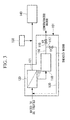
- FIG. 1 is a schematic view of a water treatment system according to the first embodiment of the present invention.
- a water treatment system 1 of the first embodiment includes a deionization unit 10 and an ion-selective removing unit 20 in the order from the upstream side of the water to be treated.
- the water to be treated contains cations such as alkali metal ions such as Na + and K + , alkaline earth metal ions such as Ca 2+ and Ba 2+ , and Mg 2+ , and anions such as F - , Cl - , Br - , I - , NO 3 - , SO 4 2- , HSO 4 - , SO 3 2- , HSO 3 - , CO 3 2- , HCO 3 - , PO 4 3- , HS - , and S 2- .
- the ions mentioned above are merely exemplifications, so that the ions are not limited to these alone.
- the alkaline earth metal ions Ca 2+ , Sr 2+ , Ba 2+ ), Mg 2+ , sulfate-based ions (SO 4 2- , SO 3 2- ) carbonate-based ions (HCO 3 - , CO 3 2- ), phosphate ions (PO 4 3- ), sulfide ions (HS - , S 2- ), and F - are scale component ions.
- a state in which the concentration of salts containing the above scale component ions in the water exceeds the saturation solubility is continued, a scale is produced.
- the period of time from the time point at which the concentration of the salts exceeds the saturation solubility to the time point at which the scale is produced changes depending on the conditions such as the ion concentration and the pH.
- the scale production can be prevented. Therefore, when the ratio of removal of the divalent or more ions is raised in the water treatment system 1, the scale deposition can be prevented even when monovalent scale component ions such as F - and HCO 3 - remain.
- water to be treated in which the scale component constructed by containing divalent or more ions is close to the saturation solubility or higher than the saturation solubility because the divalent or more ion concentration / total ion concentration or the divalent or more ion concentration / monovalent ion concentration is high is an object of treatment.
- the above water to be treated is specifically blow-down water discharged from a cooling tower, mine waste water, desulfurization waste water, or the like.
- the above water to be treated has a property such that production of a scale is feared.
- a discharging passageway 16 is disposed on the downstream side of the deionization unit 10.
- the discharging passageway 16 is branched in the midway of the passageway to a treated water discharging passageway 17 and a concentrated water discharging passageway 18.
- Valves V1, V2 are placed in the treated water discharging passageway 17 and the concentrated water discharging passageway 18, respectively.
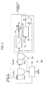
- FIG. 2 is a schematic view of the deionization unit.
- the deionization unit 10 includes a pair of opposing porous electrodes 11, 13 and a flow passageway 15 in which supplied water can pass between the electrodes.
- An anion-exchange membrane 12 is placed on the flow passageway side surface of the electrode 11, and a cation-exchange membrane 14 is placed on the flow passageway side surface of the electrode 13.
- the ion-selective removing unit 20 is connected to the treated water discharging passageway 17.
- the ion-selective removing unit 20 is an apparatus that can separate divalent or more ions at a high efficiency from the water containing various ions.
- the ion-selective removing unit 20 is an apparatus provided with a nanofilter having ion selectivity. With the nanofilter interposed, the upstream side is a concentrating unit, and the downstream side is a treatment unit.
- the nanofilter is a filter having numerous pores of about 1 to 2 nm.
- the ratio (separation ratio) of removing divalent or more ions of the nanofilter that can be used in the present embodiment is 80% or more, preferably 98% or more, and more preferably 99.8% or more, and the ratio of removing other ions such as monovalent ions is 45 to 80%.
- the ion-selective removing unit 20 includes a removed water discharging unit 21 and a multivalent ion concentrated water discharging unit 22.
- the removed water discharging unit 21 is connected to the treatment unit.
- the multivalent ion concentrated water discharging unit 22 is connected to the concentrating unit.
- a circulating unit 30 that connects between the multivalent ion concentrated water discharging unit 22 and a pipe on the upstream side of the deionization unit 10 may be placed in the water treatment system 1 of the present embodiment, as shown in FIG. 1 .
- the water to be treated having the above-described property flows into the deionization unit 10.
- the deionization unit 10 performs a deionization step and a regeneration step described below.
- a voltage is applied to the respective electrodes 11, 13 of the deionization unit 10 so that the electrode 11 becomes positive and the electrode 13 becomes negative.
- the above-described energization state is referred to as "positive".
- the valve V1 is opened, and the valve V2 is closed.
- the water to be treated having a reduced ion concentration is discharged from the deionization unit 10 as treated water, passes through the treated water discharging passageway 17, and is discharged to outside of the system of the deionization treatment apparatus so as to be collected.
- a voltage is applied to the respective electrodes 11, 13 so that the electrode 11 becomes negative and the electrode 13 becomes positive.
- the electrodes are brought into a "reverse" energized state.
- the valve V1 is closed, and the valve V2 is opened. This starts the regeneration step.
- the ions adsorbed in the deionization step are eliminated from the electrodes 11, 13 and return to the flow passageway 15.
- the cations and anions that return to the flow passageway 15 are accumulated in the flow passageway 15 because the cations and the anions cannot permeate through the anion-exchange membrane 12 and the cation-exchange membrane 14, respectively.
- purified water (clean water) is supplied from a system not illustrated in FIG. 1 or 2 .
- the ions released to the flow passageway 15 are discharged from the deionization unit 10 together with the clean water.
- the water discharged from the deionization unit 10 passes through the concentrated water discharging passageway 18 as concentrated water and are discharged to outside of the water treatment system 1.
- the deionization step and the regeneration step described above are alternately carried out each after a predetermined period of time passes.
- the deionization step and the regeneration step are each carried out for 1 to 60 minutes, preferably 1 to 10 minutes.
- the treated water discharged from the deionization unit 10 flows into the ion-selective removing unit 20.
- An amount of ions corresponding to the separation ratio among the ions contained in the treated water of the deionization unit cannot permeate through the nanofilter and hence remain in the concentrating unit.
- divalent or more ions are removed by the ion-selective removing unit, so that the treated water is separated into water (multivalent ion concentrated water) containing divalent or more ions at a high concentration in the concentrating unit and water from which most of the divalent or more ions are removed (in which the concentration of divalent or more ions is reduced to 2% or less) in the treatment unit located on the downstream side.
- the multivalent ion concentrated water passes through the circulating unit 30 to be supplied to the upstream side of the deionization unit 10.
- the multivalent ion concentrated water supplied to the upstream side of the deionization unit 10 is mixed with the water to be treated and is subjected to the deionization process in the deionization step in the deionization unit 10.
- the multivalent ion concentrated water is discharged through the multivalent ion concentrated water discharging unit 22 to outside of the water treatment system 1.
- Table 1 shows a result of simulation when water containing ions is treated in the water treatment system of FIG. 1 as Example 1.
- Table 1 shows the concentration of ions and the total dissolved solid (TDS) concentration contained in the water to be treated (mine waste water) and the water that passes through the pipes L 1-1 to L 1-5 .
- the positions of the pipes L 1-1 to L 1-5 are as follows.
- TDS concentration, ion concentration (mg/l) Water to be treated L 1-1 L 1-2 L 1-3 L 1-4 L 1-5
- TDS 6500 6778 1356 31336 8587 34
- 0.1 SO 4 2- 4400 4601 920 21371 6083 9 CO 3 2- /HCO 3 - 465 458 92 2125 403 37 Cl - 45 44 8.9 206 39 4 NO 3 - 1.2 1.3 0.3 5.9 1.7 0.003
- TDS concentration, ion concentration (mg/l) Water to be treated Treated water Concentrate water TDS 6500 1300 27300 Ca 2+ 595 119 2499 Mg 2+ 750 150 3150 Na + 140 28 588 K + 85 17 357 NH 4
- Example 1 the TDS concentration in the treated water of L 1-5 is reduced as compared with the water treatment system of Comparative Example 1 in which the water to be treated having the same property is treated.
- the concentration of Ca 2+ , Mg 2+ , and SO 4 2- which are divalent or more ions constituting a scale is greatly reduced.
- HCO 3 - which is a scale component ion remains to some extent in the treated water (L 1-5 )
- scale deposition is not generated because the divalent metal ion concentration is low.
- the divalent or more ion concentration can be reduced to be extremely low when water treatmemt is carried out in the water regenerating treatment system having the construction of the first embodiment, so that it is advantageous in suppressing scale deposition.
- an ion concentrating unit 40 is disposed on the downstream side of the removed water discharging unit 21 of the ion-selective removing unit 20, as shown in FIG. 1 .
- the ion concentrating unit 40 is an apparatus in which the ions in the water that passes through the deionization unit 10 and the ion-selective removing unit 20 are further concentrated. Examples of the ion concentrating unit 40 include a deionization apparatus, a boiler, and a cooling tower.
- a reverse osmosis membrane apparatus an electrodialyzer (ED), an electro de-ionization device (EDI), or a ion-exchange resin apparatus can be disposed, and also the same deionization apparatus (capacitive de-ionization device) as the deionization unit 10 or the like can be disposed.
- ED electrodialyzer
- EDI electro de-ionization device
- ion-exchange resin apparatus ion-exchange resin apparatus
- the reverse osmosis membrane apparatus is an apparatus having a reverse osmosis membrane having pores (about 0.5 nm) smaller than those of a nanofilter and having a higher ion removing ratio than the nanofilter.
- a reverse osmosis membrane apparatus is disposed as the ion concentrating unit 40, the ions (monovalent ions) remaining in the water that passes through the deionization unit 10 and the ion-selective removing unit 20 are removed in the reverse osmosis membrane apparatus.
- a construction may be adopted in which a plurality of reverse osmosis membrane apparatus is connected in series. The scale deposition in the reverse osmosis membrane apparatus is suppressed because the concentration of divalent or more ions that are a scale in the water to be treated in the reverse osmosis membrane apparatus is greatly reduced by the water treatment system 1 of the present embodiment.
- an evaporator and a crystallizer may be disposed downstream of the concentrating unit side of the reverse osmosis membrane apparatus.
- water is evaporated from the concentrated water, and the ions contained in the concentrated water are deposited as a solid and collected as a solid.
- a pH adjusting unit 50 is further disposed on the downstream side of the ion-selective removing unit 20 and on the upstream side of the ion concentrating unit 40, as shown in FIG. 1 .
- the water to be treated contains ionic silica or silica having a solid form that is not ionized as other scale components.
- the ionic silica permeates through the water treatment system 1 because the removing ratio in the deionization unit and the ion-selective removing unit is low.
- the non-ionic silica permeates through the water treatment system 1.
- the treated water after being treated in the water treatment system 1 contains ionic silica or silica having a solid form.
- the solubility of silica that is present in water changes depending on the pH value, and the silica is considerably dissolved in water as ionic silica when the pH value is 9 or more.
- the pH adjusting unit 50 puts an alkali agent into the water so that the pH value (measured by pH not illustrated in FIG. 3 ) of the water that passes between the ion-selective removing unit 20 and the ion concentrating unit 40 becomes 9 or more.
- the alkali agent is an aqueous solution of hydroxide of an alkali metal such as Na or K.
- the scale production can be suppressed when a reverse osmosis membrane apparatus is disposed at a later stage.
- the water having a reduced concentration of divalent or more ions that is discharged from the removed water discharging unit 21 of the ion-selective removing unit 20 is used as boiler-feeding water. Since water is evaporated from the boiler water by using, the boiler water before make-up is brought into a state having a high ion concentration. Therefore, scale production caused by concentration in the boiler can be prevented by using the boiler-feeding water in which the divalent or more ion concentration is greatly reduced by the water treatment system 1 of the present embodiment.
- the cooling tower By combining the cooling tower with the water treatment system 1 of the present embodiment, the water in which the ion concentration is sufficiently reduced is used in the cooling tower. For this reason, the degree of concentrating in the cooling tower can be increased, thereby improving the efficiency of using water in the cooling tower. Also, since the divalent or more ion concentration is greatly reduced by the water treatment system 1 of the present embodiment, scale production caused by concentration in the cooling tower can be prevented.
- a construction may be adopted in which, by combining with a deionization apparatus, the treated water produced by the deionization apparatus is fed to the boiler or the cooling tower.
- a construction may be adopted in which the water (water from which ions are removed) discharged from the evaporator and the crystallizer disposed on the downstream side of the concentrating unit of the reverse osmosis membrane apparatus is fed to the cooling tower or the boiler.
- the water treatment system 1 of the present embodiment produces water in which the divalent or more ion concentration is reduced, the water treatment system 1 can be used also for producing water for washing in which the presence of alkaline earth metal ions raises a problem.
- FIGS. 3 and 4 are schematic views of water treatment systems according to the second embodiment of the present invention.
- water in which the scale component constructed by containing divalent or more ions is close to the saturation solubility or lower than the saturation solubility is an object of treatment.
- the water may be river water, sewage treated water, brine water, factory waste water, factory waste water treated water, or the like.
- the sewage treated water and the factory waste water treated water are water after organic substances, harmful substances, and the like are removed.
- a pretreatment unit and an organic substance treatment unit may be disposed on the upstream side of the water treatment system.
- oily components, heavy metals, floating particles, and the like in the water to be treated are removed from the water to be treated.
- the organic substance treatment unit has a construction in which a biological treatment unit that decomposes and removes organic substances by using microorganism, a chemical oxidation treatment unit that performs a chemical oxidation treatment on the organic substances, activated carbon, and an ultraviolet treatment apparatus are suitably combined.
- Water treatment systems 101, 201 of FIGS. 3 and 4 include a deionization unit 110 and an ion-selective removing unit 120 having a construction similar to those of the first embodiment.
- the ion-selective removing unit 120 is disposed upstream of the deionization unit 110.
- an ion concentrating unit 140 and a pH adjusting unit 150 may be provided on the downstream side of the water treatment systems 101, 201.
- An removed water discharging unit 121 of the ion-selective removing unit 120 is connected to the ion concentrating unit 140.
- a multivalent ion concentrated water discharging unit 122 of the ion-selective removing unit 120 is connected to the deionization unit 110.
- a treated water discharging passageway 117 of the deionization unit 110 is connected to the ion concentrating unit 140.
- the treated water discharging passageway 117 of the deionization unit 110 passes through a circulating unit 130 to be connected to a pipe located on the upstream side of the ion-selective removing unit 120.
- FIG. 3 In accordance with the water quality of the water to be treated, a construction of either FIG. 3 or FIG. 4 is selected.
- the circulating unit need not be provided, as shown in FIG. 4 , when the divalent or more ion concentration in the water to be treated is extremely low and the divalent or more ion concentration in the treated water of the deionization unit 110 is sufficiently reduced.
- the water to be treated flows into the ion-selective removing unit 120.
- the ion-selective removing unit 120 separates the water to be treated into multivalent ion concentrated water and water having a reduced concentration of divalent or more ions.
- the water having a reduced concentration of divalent or more ions passes through the removed water discharging unit 121 to be discharged from the ion-selective removing unit 120.
- the discharged water is fed to the ion concentrating unit 140.
- the multivalent ion concentrated water passes through the multivalent ion concentrated water discharging unit 122 to be discharged from the ion-selective removing unit 120 and fed to the deionization unit 110.
- the deionization unit 110 performs a deionization step and a regeneration step similar to those of the first embodiment, to treat the multivalent ion concentrated water.
- the divalent or more ions in the multivalent ion concentrated water are adsorbed and removed in the deionization step.
- the concentrated water produced by the regeneration step passes through the concentrated water discharging passageway 118 to be discharged to outside of the water treatment system 101 of FIG. 3 or the water treatment system 201 of FIG. 4 .
- the treated water passes through the treated water discharging passageway 117 and the circulating unit 130 to be fed to the ion-selective removing unit 120.
- the fed treated water joins with the water to be treated and flows into the ion-selective removing unit 120.
- the multivalent ion concentrated water is circulated to the ion-selective removing unit 120 after passing through the deionization unit 110.
- the treated water that is subjected to the deionization process by the deionization step passes through the treated water discharging passageway 117 to be joined with the water discharged from the ion-selective removing unit 120 and having a reduced concentration of divalent or more ions. Thereafter, the treated water is fed to the ion concentrating unit 140 together with the water having a reduced concentration of divalent or more ions.
- Table 3 shows a result of simulation when water containing ions is treated in the water treatment system of FIG. 3 as Example 2.
- Table 3 shows the concentration of ions and the total dissolved solid (TDS: Total Dissolved Solids) concentration contained in the water to be treated (factory waste water) and the water that passes through the pipes L 2-1 to L 2-5 .
- the positions of the pipes L 2-1 to L 2-5 are as follows.
- the concentration of divalent or more ions (Ca 2+ , Mg 2+ , SO 4 2- ) in the treated water of L 2-5 is greatly reduced as compared with the water treatment system of Comparative Example 2 in which the water to be treated having the same property is treated.
- the divalent or more ion concentration in the treated water of L 2-4 is further more reduced than in Table 3. Therefore, a circulating unit need not be provided, as shown in FIG. 4 , when the water quality of the treated water of the deionization unit (corresponding to L 2-4 of Table 3) is of the same degree as the water quality of the after-removal water of the ion-selective removing unit (corresponding to L 2-5 of Table 3).
- the ion concentrating unit 140 may include a deionization apparatus, a boiler, and a cooling tower in the same manner as in the first embodiment, and a construction in which these are combined may be adopted.
- an evaporator or a crystallizer may be disposed on the downstream side of the reverse osmosis membrane apparatus.
- a pH adjusting unit 50 for suppressing deposition of silica by adjusting the pH value of the water is further disposed on the upstream side of the ion concentrating unit 140 and on the downstream side of the water treatment system.
- scale production can be suppressed when a reverse osmosis membrane apparatus is disposed at a later stage.
- the ion removing ratio and the water collection ratio can be advantageously raised when the water to be treated in which the scale component constructed by containing divalent or more ions is close to the saturation solubility or lower than the saturation solubility is treated.
- the treated water of the deionization unit 110 is supplied again to the ion-selective removing unit 120, so that the divalent or more ion concentration in the treated water discharged from the ion-selective removing unit 120 is greatly reduced. For this reason, the scale production in the apparatus disposed on the downstream side of the water treatment system 101, 201 can be effectively suppressed.
- the water treated by the water treatment system 101, 201 of the second embodiment can be used as water for washing because the alkaline earth metal ions are reduced.
- FIG. 5 is a schematic view describing a construction in which, as a third embodiment of the present invention, Ca is separated and collected as a solid from the concentrated water of the deionization unit in the water treatment system of the first embodiment.
- a concentrated water discharging passageway 18 of a water treatment system 1 is connected to a separation unit 300.
- the separation unit 300 includes a precipitation unit 301 and a dehydration unit 302.
- FIG. 5 exemplifies a case in which CaCO 3 is collected from the concentrated water containing Ca 2+ and CO 3 2- as major scale component ions in the water treatment system of FIG. 1 .
- the separation unit 300 of FIG. 5 includes a first precipitation apparatus 301a and a second precipitation apparatus 301b as the precipitation unit 301.
- the concentrated water discharging passageway 18 is connected to the first precipitation apparatus 301a, and the concentrated water of the deionization unit 10 is supplied to the first precipitation apparatus 301a.
- Ca(OH) 2 is put into the first precipitation apparatus 301a.
- CaCO 3 becomes supersaturated, CaCO 3 is deposited and precipitated at the bottom part of the first precipitation apparatus 301a.
- the heavy metals contained in the concentrated water also are precipitated at the bottom part of the first precipitation apparatus 301a.
- the first precipitation apparatus 301a and the second precipitation apparatus 301b are connected to each other.
- supernatant liquid containing Ca 2+ is fed from the first precipitation apparatus 301a to the second precipitation apparatus 301b.
- Na 2 CO 3 is put into the second precipitation apparatus 301b, and Ca 2+ is deposited as CaCO 3 and precipitated at the bottom part.
- the supernatant liquid in the second precipitation apparatus 301b contains the scale component ions that cannot be separated in the first precipitation apparatus 301a and the second precipitation apparatus 301b.
- the supernatant liquid of the second precipitation apparatus 301b is discharged from the second precipitation apparatus 301b and supplied to the upstream side of the deionization unit 10.
- the second precipitation apparatus 301b may be connected to the treated water discharging passageway 17, and the supernatant liquid of the second precipitation apparatus 301b may be supplied to the ion-selective removing unit 20.
- the destination of supply of the supernatant liquid can be suitably selected in accordance with the property of the supernatant liquid, the property of the water to be treated, and the property of the treated water of the deionization unit 10.
- the bottom parts of the first precipitation apparatus 301a and the second precipitation apparatus 301b are connected to the dehydration unit 302.
- Water containing a precipitate is discharged from the bottom parts of the first precipitation apparatus 301a and the second precipitation apparatus 301b and fed to the dehydration unit 302.
- the dehydration unit 302 separates water from the solid substance, and a sludge containing CaCO 3 is collected.
- the water separated in the dehydration unit 302 is circulated to the first precipitation apparatus 301a.
- FIG. 6 is a schematic view describing a construction in which, as a fourth embodiment of the present invention, Ca is separated and collected as a solid from the concentrated water of the deionization unit in the water treatment system of the second embodiment.
- FIG. 6 exemplifies a case in which CaCO 3 is collected from the concentrated water containing Ca 2+ and CO 3 2- as major scale component ions in the water treatment system of FIG. 3 .
- the same constituent elements as appear in FIG. 5 are denoted with the same reference signs.
- FIG. 6 shows a construction in which the supernatant liquid of the second precipitation apparatus 301b is circulated to the upstream side of the ion-selective removing unit 120.
- the second precipitation apparatus 301b may be connected to a pipe between the ion-selective removing unit 120 and the deionization unit 110, and the supernatant liquid of the second precipitation apparatus 301b may be circulated to the deionization unit 110.
- the destination of supply of the supernatant liquid can be suitably selected in accordance with the property of the supernatant liquid, the property of the water to be treated, and the property of the multivalent ion concentrated water of the ion-selective removing unit 120.
- the water after collecting the sludge from the concentrated water of the deionization unit is circulated to the water treatment system, so that the water collecting ratio can be further more improved.
- FIG. 7 is a schematic view describing a construction in which, as a fifth embodiment of the present invention, a separation unit is disposed upstream of the water treatment system of the first embodiment.
- FIG. 7 shows an example of a construction connected to the water treatment system of FIG. 1 , where the scale component ions in the water to be treated are mainly Ca 2+ and CO 3 2- .
- the same constituent elements as appear in FIG. 5 are denoted with the same reference signs.
- the separation unit 500 of the fifth embodiment includes a precipitation unit 301 and a dehydration unit 302 in the same manner as in the third embodiment.
- the supernatant liquid of the second precipitation apparatus 301b is fed to the deionization unit 10 of the first embodiment.
- the construction of the separation unit 500 other than that is the same as in the third embodiment.
- the circulating unit 30 is connected to a pipe between the second precipitation apparatus 301b and the deionization unit 10, and the multivalent ion concentrated water of the ion-selective removing unit 20 is fed to the deionization unit 10 together with the supernatant liquid.
- a construction may be adopted in which the circulating unit 30 is connected to the first precipitation apparatus 301a, and the multivalent ion concentrated water is fed to the first precipitation apparatus 301a.
- the construction of the fifth embodiment is effective when the water to be treated has a water quality in which Ca 2+ exceeds the saturation concentration.
- the deionization unit 10 cannot remove Ca 2+ sufficiently, and the treated water of the deionization unit 10 flows into the ion-selective removing unit 20 in a state in which the Ca 2+ concentration in the treated water of the deionization unit 10 is high.
- the Ca 2+ concentration on the concentrating unit side of the ion-selective removing unit 20 becomes high, thereby raising a fear that a scale may be produced in the ion-selective removing unit 20.
- Ca 2+ in the water to be treated is removed in advance, and the concentration of the water to be treated can be reduced to be close to the saturation concentration of Ca 2+ immediately before flowing into the water treatment system 1. Therefore, scale production in the apparatus disposed at a stage posterior to the separation unit 500, that is, in the ion-selective removing unit and the ion concentrating unit, can be prevented.
- FIG. 8 is a schematic view describing a construction in which, as a sixth embodiment of the present invention, a separation unit is disposed upstream of the water treatment system of the second embodiment.
- FIG. 8 shows an example of a construction connected to the water treatment system of FIG. 3 , where the scale component ions in the water to be treated are mainly Ca 2+ and CO 3 2- .
- the same constituent elements as appear in FIG. 5 are denoted with the same reference signs.
- a construction may be adopted in which a separation unit is disposed in the water treatment system of FIG. 4 .
- the separation unit 600 of the sixth embodiment includes a precipitation unit 301 and a dehydration unit 302 in the same manner as in the third embodiment.
- the supernatant liquid of the second precipitation apparatus 301b is fed to the ion-selective removing unit 120 of the second embodiment.
- the construction of the separation unit 600 other than that is the same as in the fourth embodiment.
- the concentrated water discharging passageway 118 is connected to the first precipitation apparatus 301a, and the concentrated water of the deionization unit 110 is fed to the first precipitation apparatus 301a.
- a construction may be adopted in which the concentrated water discharging passageway 118 is connected to a pipe between the second precipitation apparatus 301b and the ion-selective removing unit 120, and the concentrated water is fed to the ion-selective removing unit 120.
- the pH value at the precipitation unit 301 is adjusted to be about 10, so as to lower the saturation solubility of CaCO 3 to facilitate deposition.
- the water treatment system is preferably under conditions such that CaCO 3 is hardly deposited (specifically, about pH 7). Therefore, in the case of collecting CaCO 3 , it is preferable that a neutralization unit (not illustrated in the drawings) is provided on the downstream side of the second precipitation apparatus 301b, and the supernatant liquid discharged from the second precipitation apparatus 301b is fed to the deionization unit and the ion-selective removing unit after the pH value of the supernatant liquid is adjusted to be about 7 in the neutralization unit.
- the scale component ions of the water to be treated are a combination other than Ca 2+ and CO 3 2-
- the scale component ions can be collected as a solid by providing a separation unit in the same manner as in the third to sixth embodiments. Also, by providing an arrangement similar to that of the fifth and sixth embodiments, the concentration of scale component ions other than Ca 2+ and CO 3 2- can be reduced.
- CaSO 4 has a low solubility to water.
- the separation unit mainly collects CaSO 4 , the second precipitation apparatus is unnecessary, so that a construction may be adopted in which the supernatant liquid of the first precipitation apparatus is circulated to the upstream side of the deionization unit or the ion-selective removing unit.
Landscapes
- Chemical & Material Sciences (AREA)
- Engineering & Computer Science (AREA)
- Water Supply & Treatment (AREA)
- Chemical Kinetics & Catalysis (AREA)
- Health & Medical Sciences (AREA)
- Life Sciences & Earth Sciences (AREA)
- Urology & Nephrology (AREA)
- Molecular Biology (AREA)
- Analytical Chemistry (AREA)
- Electrochemistry (AREA)
- General Chemical & Material Sciences (AREA)
- Hydrology & Water Resources (AREA)
- Environmental & Geological Engineering (AREA)
- Organic Chemistry (AREA)
- Separation Using Semi-Permeable Membranes (AREA)
- Water Treatment By Electricity Or Magnetism (AREA)
- Removal Of Specific Substances (AREA)
- Treatment Of Water By Ion Exchange (AREA)
Applications Claiming Priority (1)
| Application Number | Priority Date | Filing Date | Title |
|---|---|---|---|
| PCT/JP2013/061461 WO2014170981A1 (ja) | 2013-04-18 | 2013-04-18 | 水処理システム |
Publications (2)
| Publication Number | Publication Date |
|---|---|
| EP2949629A1 true EP2949629A1 (de) | 2015-12-02 |
| EP2949629A4 EP2949629A4 (de) | 2016-04-20 |
Family
ID=51730952
Family Applications (1)
| Application Number | Title | Priority Date | Filing Date |
|---|---|---|---|
| EP13882298.6A Withdrawn EP2949629A4 (de) | 2013-04-18 | 2013-04-18 | Wasserbehandlungssystem |
Country Status (4)
| Country | Link |
|---|---|
| US (1) | US20160096141A1 (de) |
| EP (1) | EP2949629A4 (de) |
| JP (1) | JP6189422B2 (de) |
| WO (1) | WO2014170981A1 (de) |
Families Citing this family (3)
| Publication number | Priority date | Publication date | Assignee | Title |
|---|---|---|---|---|
| CN110342680A (zh) * | 2019-07-08 | 2019-10-18 | 上海水诺环保科技有限公司 | 一种铅酸废水处理工艺 |
| JP6982668B1 (ja) * | 2020-08-31 | 2021-12-17 | 大同メタル工業株式会社 | 浄化装置 |
| JP7105290B2 (ja) * | 2020-11-06 | 2022-07-22 | 大同メタル工業株式会社 | 回収システム |
Family Cites Families (19)
| Publication number | Priority date | Publication date | Assignee | Title |
|---|---|---|---|---|
| JPS516350A (en) * | 1974-07-08 | 1976-01-19 | Tore Eng Co Ltd | Datsuennoshukusuino shorihoho |
| JPS62294484A (ja) * | 1986-06-13 | 1987-12-21 | Shinko Fuaudoraa Kk | 高濃度のシリカを含む水の逆浸透処理法 |
| US5503729A (en) * | 1994-04-25 | 1996-04-02 | Ionics Incorporated | Electrodialysis including filled cell electrodialysis (electrodeionization) |
| JP4135802B2 (ja) * | 1999-09-27 | 2008-08-20 | オルガノ株式会社 | 脱塩装置 |
| JP2002273437A (ja) * | 2001-03-22 | 2002-09-24 | Kurita Water Ind Ltd | 脱塩装置 |
| JP2002336859A (ja) * | 2001-05-18 | 2002-11-26 | Kurita Water Ind Ltd | 脱塩水製造方法 |
| JP2003300069A (ja) * | 2002-04-09 | 2003-10-21 | Toray Ind Inc | 造水方法及び造水装置 |
| EP2070583B1 (de) * | 2002-08-02 | 2012-07-04 | University Of South Carolina | Gewinnung von gereinigtem Wasser und hochwertigen Chemikalien aus Salzwasser |
| WO2006031732A2 (en) * | 2004-09-13 | 2006-03-23 | University Of South Carolina | Water desalination process and apparatus |
| US7744760B2 (en) * | 2006-09-20 | 2010-06-29 | Siemens Water Technologies Corp. | Method and apparatus for desalination |
| US7813106B2 (en) * | 2006-12-19 | 2010-10-12 | General Electric Company | High current efficiency supercapacitor desalination devices and methods of making the same |
| EP2109587A1 (de) * | 2007-02-01 | 2009-10-21 | General Electric Company | Entsalzungsverfahren und vorrichtung mit superkondensator-elektroden |
| US9776137B2 (en) * | 2008-11-12 | 2017-10-03 | Board Of Regents, The University Of Texas System | Recovery of regenerant electrolyte |
| JP5330901B2 (ja) * | 2009-05-28 | 2013-10-30 | 三菱重工業株式会社 | 塩及び淡水の併産装置及び方法 |
| CN102167463B (zh) * | 2010-02-26 | 2014-05-14 | 通用电气公司 | 水处理装置及方法 |
| WO2013006438A1 (en) * | 2011-07-01 | 2013-01-10 | Siemens Pte. Ltd. | Electrodesalination system and method |
| WO2014020758A1 (ja) * | 2012-08-03 | 2014-02-06 | 三菱重工メカトロシステムズ株式会社 | 脱塩処理装置及び脱塩処理装置の運転方法 |
| US20140091039A1 (en) * | 2012-09-28 | 2014-04-03 | General Electric Company | System and method for the treatment of hydraulic fracturing backflow water |
| PL2962997T3 (pl) * | 2013-04-01 | 2018-12-31 | Mitsubishi Heavy Industries, Ltd. | System uzdatniania wody |
-
2013
- 2013-04-18 WO PCT/JP2013/061461 patent/WO2014170981A1/ja not_active Ceased
- 2013-04-18 JP JP2015512242A patent/JP6189422B2/ja not_active Expired - Fee Related
- 2013-04-18 US US14/366,523 patent/US20160096141A1/en not_active Abandoned
- 2013-04-18 EP EP13882298.6A patent/EP2949629A4/de not_active Withdrawn
Also Published As
| Publication number | Publication date |
|---|---|
| JPWO2014170981A1 (ja) | 2017-02-16 |
| EP2949629A4 (de) | 2016-04-20 |
| JP6189422B2 (ja) | 2017-08-30 |
| WO2014170981A1 (ja) | 2014-10-23 |
| US20160096141A1 (en) | 2016-04-07 |
Similar Documents
| Publication | Publication Date | Title |
|---|---|---|
| JP3909793B2 (ja) | 高濃度の塩類を含有する有機性廃水の処理方法及びその装置 | |
| CN101094813B (zh) | 带有过滤组件的edi浓缩物循环回路 | |
| KR101530571B1 (ko) | 냉각탑 보충수 탈염 및 폐수 재활용 시스템 | |
| CN107381729B (zh) | 一种电渗析反应器及脱硫废水的处理方法 | |
| CN102351352A (zh) | 一种电渗析-高效蒸发处理矿冶废水膜过滤浓缩液的方法 | |
| JP5955389B2 (ja) | 脱塩処理装置及び脱塩処理装置の運転方法 | |
| EP2962997B1 (de) | Wasserbehandlungssystem | |
| US20160185619A1 (en) | Water treatment system and method | |
| US20140091039A1 (en) | System and method for the treatment of hydraulic fracturing backflow water | |
| AU2006285207A1 (en) | Acid mine water demineralization methods | |
| EP2531450B1 (de) | Anlage und verfahren zur herstellung von entmineralisiertem wasser, insbesondere zur verwendung in anlagen zur stromgewinnung | |
| JP5293551B2 (ja) | 水処理システム | |
| EP2949629A1 (de) | Wasserbehandlungssystem | |
| CN205662404U (zh) | 一种零排放水处理装置 | |
| CN205662395U (zh) | 一种循环水处理装置 | |
| JP4697758B2 (ja) | 脱塩排水の処理方法及び装置 | |
| CN102897947A (zh) | 高硫酸根废水超高水回收率ro脱盐处理方法及处理系统 | |
| CN216106440U (zh) | 一种长效净水系统和净水设备 | |
| KR102357480B1 (ko) | 수처리 장치 | |
| CN204958639U (zh) | 一种高盐水处理装置 | |
| US20200032398A1 (en) | Surface treatment plant, preconditioning apparatus and process for treating process medium and/or rinsing medium | |
| JP5998796B2 (ja) | シリカ除去システム及びそれを備える水処理システム | |
| JP6027881B2 (ja) | 無電解ニッケルりんめっき液の再生方法及び再生装置 | |
| JP4531213B2 (ja) | 脱塩装置 | |
| NL2021733B1 (en) | Method for the production of drinking water |
Legal Events
| Date | Code | Title | Description |
|---|---|---|---|
| PUAI | Public reference made under article 153(3) epc to a published international application that has entered the european phase |
Free format text: ORIGINAL CODE: 0009012 |
|
| 17P | Request for examination filed |
Effective date: 20150828 |
|
| AK | Designated contracting states |
Kind code of ref document: A1 Designated state(s): AL AT BE BG CH CY CZ DE DK EE ES FI FR GB GR HR HU IE IS IT LI LT LU LV MC MK MT NL NO PL PT RO RS SE SI SK SM TR |
|
| AX | Request for extension of the european patent |
Extension state: BA ME |
|
| A4 | Supplementary search report drawn up and despatched |
Effective date: 20160317 |
|
| RIC1 | Information provided on ipc code assigned before grant |
Ipc: C02F 1/44 20060101ALI20160311BHEP Ipc: B01D 61/14 20060101ALI20160311BHEP Ipc: C02F 1/58 20060101ALI20160311BHEP Ipc: B01D 61/16 20060101ALI20160311BHEP Ipc: C02F 1/469 20060101AFI20160311BHEP |
|
| DAX | Request for extension of the european patent (deleted) | ||
| RAP1 | Party data changed (applicant data changed or rights of an application transferred) |
Owner name: MITSUBISHI HEAVY INDUSTRIES ENGINEERING, LTD. |
|
| 17Q | First examination report despatched |
Effective date: 20181023 |
|
| STAA | Information on the status of an ep patent application or granted ep patent |
Free format text: STATUS: THE APPLICATION IS DEEMED TO BE WITHDRAWN |
|
| 18D | Application deemed to be withdrawn |
Effective date: 20191107 |