EP2949794A1 - Métier à filer et procédé de filage - Google Patents
Métier à filer et procédé de filage Download PDFInfo
- Publication number
- EP2949794A1 EP2949794A1 EP15166315.0A EP15166315A EP2949794A1 EP 2949794 A1 EP2949794 A1 EP 2949794A1 EP 15166315 A EP15166315 A EP 15166315A EP 2949794 A1 EP2949794 A1 EP 2949794A1
- Authority
- EP
- European Patent Office
- Prior art keywords
- spinning
- air
- injecting
- pneumatic
- yarn
- Prior art date
- Legal status (The legal status is an assumption and is not a legal conclusion. Google has not performed a legal analysis and makes no representation as to the accuracy of the status listed.)
- Granted
Links
- 238000009987 spinning Methods 0.000 title claims abstract description 226
- 238000000034 method Methods 0.000 title claims description 9
- 239000000835 fiber Substances 0.000 claims abstract description 110
- 238000002347 injection Methods 0.000 claims description 15
- 239000007924 injection Substances 0.000 claims description 15
- 238000005304 joining Methods 0.000 description 13
- 238000004804 winding Methods 0.000 description 12
- 230000007547 defect Effects 0.000 description 11
- 238000001514 detection method Methods 0.000 description 10
- 238000011144 upstream manufacturing Methods 0.000 description 10
- 238000012806 monitoring device Methods 0.000 description 8
- 230000001902 propagating effect Effects 0.000 description 4
- 238000004904 shortening Methods 0.000 description 4
- 239000000463 material Substances 0.000 description 3
- 230000003111 delayed effect Effects 0.000 description 2
- 238000003860 storage Methods 0.000 description 2
- 238000004018 waxing Methods 0.000 description 2
- 230000005856 abnormality Effects 0.000 description 1
- 238000005259 measurement Methods 0.000 description 1
- 230000000149 penetrating effect Effects 0.000 description 1
- 239000000126 substance Substances 0.000 description 1
Images



Classifications
-
- D—TEXTILES; PAPER
- D01—NATURAL OR MAN-MADE THREADS OR FIBRES; SPINNING
- D01H—SPINNING OR TWISTING
- D01H1/00—Spinning or twisting machines in which the product is wound-up continuously
- D01H1/11—Spinning by false-twisting
- D01H1/115—Spinning by false-twisting using pneumatic means
Definitions
- the present invention relates to a spinning machine and a spinning method.
- a spinning machine including a draft device adapted to draft a fiber bundle and a pneumatic spinning device adapted to produce a yarn at a spinning position by applying twists to the drafted fiber bundle by injecting air to a spinning chamber
- a spinning machine for example, in a case where a yarn defect has been detected, when a drafting operation of the draft device is stopped, a fiber bundle portion to which twists have not been applied is formed at a yarn end of the yarn.
- the fiber bundle portion when accumulating the yarn in a yarn accumulating device using a yarn accumulating roller, if a length of the fiber bundle portion is excessively long, the fiber bundle portion may remain at the yarn accumulating roller. If the length of the fiber bundle portion is excessively short, a yarn end of the yarn from a winding device may not be reliably caught when performing a yarn joining operation.
- An object of the present invention is to provide a spinning machine and a spinning method that are capable of adjusting the length of the fiber bundle portion to be formed at the yarn end of the yarn.
- a spinning machine of the present invention includes a draft device adapted to draft a fiber bundle, a pneumatic spinning device arranged movable between a spinning position and a receded position that is located further away from the draft device than the spinning position, and adapted to produce a yarn at the spinning position by applying twists to the drafted fiber bundle by injecting air to a spinning chamber, and an injecting device adapted to inject air to a region between the draft device and the pneumatic spinning device.
- the injecting device is adapted to be injecting the air at least when the pneumatic spinning device is moving from the spinning position to the receded position, and to stop injecting the air before the pneumatic spinning device reaches the receded position.
- the fiber bundle is disconnected by the air.
- a length of a fiber bundle portion can be appropriately adjusted by adjusting a timing to inject the air.
- the injection of the air is stopped before the pneumatic spinning device reaches the receded position, the air can be efficiently injected, and the length of the fiber bundle portion can be adjusted.
- the injecting device may inject the air to cross a fiber passage in the region between the draft device and the pneumatic spinning device.
- the injecting device may inject the air along a direction orthogonal to the fiber passage.
- the spinning machine of the present invention may further include a suction device arranged to face the injecting device with the region therebetween and adapted to suck fibers.
- the draft device may include a plurality of roller pairs, and the roller pair arranged closest to the pneumatic spinning device among the plurality of the roller pairs may include a driving roller adapted to rotate by receiving a driving force and a driven roller adapted to rotate in accordance with the driving roller.
- the injecting device may be arranged to a side where the driven roller is arranged with respect to the region between the draft device and the pneumatic spinning device, and the suction device may be arranged to a side where the driving roller is arranged with respect to the region between the draft device and the pneumatic spinning device.
- the pneumatic spinning device may include a nozzle block and a hollow guide shaft body arranged to form the spinning chamber, and a nozzle through which the air is injected into the spinning chamber may be formed in the nozzle block.
- the spinning machine of the present invention may further include a control section adapted to control start and stop of the injection of the air from the injecting device.
- a control section adapted to control start and stop of the injection of the air from the injecting device.
- a spinning method of the present invention is executed in a spinning machine that includes a draft device adapted to draft a fiber bundle, a pneumatic spinning device arranged movable between a spinning position and a receded position that is located further away from the draft device than the spinning position, and adapted to produce a yarn at the spinning position by applying twists to the drafted fiber bundle by injecting air to a spinning chamber, and an injecting device adapted to inject air to a region between the draft device and the pneumatic spinning device.
- the spinning method includes a moving step of starting to move the pneumatic spinning device from the spinning position to the receded position, and an injecting step of injecting the air from the injecting device at least when the pneumatic spinning device is moving from the spinning position to the receded position, and stopping the injection of the air before the pneumatic spinning device reaches the receded position.
- the fiber bundle is disconnected by the air.
- a length of a fiber bundle portion can be appropriately adjusted by adjusting a timing to inject the air.
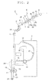
- a spinning machine 1 includes a plurality of spinning units 2, a yarn joining vehicle 3, a blower box 4, and a motor box 5.
- the plurality of spinning units 2 are arranged in a row, and each of the plurality of spinning units 2 is adapted to produce a yarn Y to wind around a package P.
- the yarn joining vehicle 3 is adapted to perform a yarn joining operation in a spinning unit 2 in which the yarn Y has been disconnected.
- the blower box 4 accommodates an air supply source adapted to generate, for example, suction flow and whirling flow in each section of the spinning unit 2, and the like.
- the motor box 5 accommodates a motor adapted to supply power to each section of the spinning unit 2, and the like.
- upstream and downstream in a travelling direction of a sliver S, a fiber bundle F, and the yarn Y are respectively referred to as “upstream” and “downstream” simply.
- a side where a travelling path of the yarn Y is located with respect to the yarn joining vehicle 3 is simply referred to as a "front side”, and a side opposite thereto is simply referred to as a "back side”.
- each spinning unit 2 includes a draft device 6, an injecting device 14 and a suction device 15, a pneumatic spinning device 7, a yarn monitoring device 8, a tension sensor 9, a yarn accumulating device 50, a waxing device 11, and a winding device 12 in this order from upstream.
- the devices are directly or indirectly supported by a machine frame 13 such that upstream becomes an upper side in a machine height direction (in other words, such that downstream becomes a lower side in the machine height direction).
- the draft device 6 is adapted to produce the fiber bundle F by drafting the sliver S.
- the draft device 6 includes a back roller pair 61, a third roller pair 62, a middle roller pair 64 each of the roller is provided with an apron belt 63, and a front roller pair 65 in this order from upstream.
- Each of the roller pairs 61, 62, 64, and 65 is adapted to transport the sliver S fed from a sliver can (not illustrated) from upstream to downstream while drafting.
- the front roller pair 65 is arranged closest to the pneumatic spinning device 7.
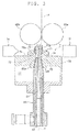
- the front roller pair 65 includes a bottom roller (a driving roller) 65a and a top roller (a driven roller) 65b.
- the bottom roller 65a is adapted to rotate by receiving a driving force from a drive motor (not illustrated).
- the top roller 65b is adapted to rotate in accordance with the bottom roller 65a.
- the pneumatic spinning device 7 is adapted to inject air and apply twists to the fiber bundle F drafted by the draft device 6 to produce the yarn Y while being located at a spinning position.
- the spinning position is a position where the pneumatic spinning device 7 is arranged to be close to the draft device 6 (specifically, the front roller pair 65) at the time of spinning, and is a position where the pneumatic spinning device 7 is located when the fiber bundle F is fed from the draft device 6 to the pneumatic spinning device 7.
- the pneumatic spinning device 7 includes a nozzle block 70 and a hollow guide shaft body 80.
- the hollow guide shaft body 80 is inserted into the nozzle block 70 from downstream.
- An internal space formed by the nozzle block 70 and the hollow guide shaft body 80 at this time is a spinning chamber 73.
- the nozzle block 70 includes a fiber guiding section 71 and a whirling flow generating section 72.
- the fiber guiding section 71 is provided with a guiding hole 71a adapted to guide the fiber bundle F fed from the draft device 6 to the spinning chamber 73.
- the fiber guiding section 71 is also provided with a needle 75.
- a tip-end portion 75a of the needle 75 is located in the spinning chamber 73.
- the needle 75 has a function to prevent twists from propagating upstream of the spinning chamber 73.
- the whirling flow generating section 72 is provided with a plurality of nozzles 74 that communicate to the spinning chamber 73. The plurality of nozzles 74 are arranged such that whirling flow is generated in the spinning chamber 73 when air is injected.
- the whirling flow generating section 72 is provided with a hole portion 72a through which the hollow guide shaft body 80 is inserted.
- the hole portion 72a is formed into a truncated cone shape that tapers off towards upstream and communicates to the spinning chamber 73.
- the hollow guide shaft body 80 can be inserted into the hole portion 72a of the whirling flow generating section 72.
- An upper-end portion 80a of the hollow guide shaft body 80 is formed into a truncated cone shape that tapers off towards upstream.
- the hollow guide shaft body 80 is provided with a passage 81 extending along a central axis of the hollow guide shaft body 80.
- the passage 81 communicates to the spinning chamber 73 at an upstream side thereof, and is formed in a widened manner towards an exit 83 located downstream.
- a collecting section 77 communicates to the spinning chamber 73 via a gap formed between the upper-end portion 80a of the hollow guide shaft body 80 and the hole portion 72a of the whirling flow generating section 72.
- the pneumatic spinning device 7 is movably (swingably) supported by a support shaft (not illustrated). As illustrated in FIGS. 4 and 5 , the pneumatic spinning device 7 can be moved to a receded position, which is located further away from the draft device 6 than the spinning position. When the pneumatic spinning device 7 is located at the receded position, the hollow guide shaft body 80 can be further moved from the nozzle block 70. When the pneumatic spinning device 7 is moved from the spinning position to the receded position, as illustrated in FIG. 4 , the nozzle block 70 and the hollow guide shaft body 80 are integrally moved away from the draft device 6. Then, as illustrated in FIG. 5 , only the nozzle block 70 stops at a predetermined position. The hollow guide shaft body 80 continues the movement in order to be located away from the nozzle block 70. Subsequently, the hollow guide shaft body 80 that has been moved away from the nozzle block 70 stops at a predetermined position.
- the yarn monitoring device 8 is adapted to monitor the travelling yarn Y between the pneumatic spinning device 7 and the yarn accumulating device 50.
- the yarn monitoring device 8 transmits a yarn defect detection signal to a unit controller (a control section) 10 upon detection of a yarn defect.
- the yarn monitoring device 8 detects as the yarn defect, for example, an abnormality in thickness of the yarn Y and/or a foreign substance in the yarn Y.
- the yarn monitoring device 8 detects a length of the yarn Y and transmits a length detection signal to the unit controller 10.
- the tension sensor 9 is adapted to measure tension of the travelling yarn Y between the pneumatic spinning device 7 and the yarn accumulating device 50, and to transmit a tension measurement signal to the unit controller 10.
- the waxing device 11 is adapted to apply wax to the travelling yarn Y between the yarn accumulating device 50 and the winding device 12.
- the unit controller 10 is formed of, for example, a Central Processing Unit (CPU) adapted to perform arithmetic processing, a Read Only Memory (ROM) and a Random Access Memory (RAM) each adapted to function as a storage section, and the like, and is provided to every spinning unit 2.
- the unit controller 10 receives the yarn defect detection signal transmitted from the yarn monitoring device 8.
- the unit controller 10 calculates a length of the yarn Y that has been wound by the winding device 12 based on the length detection signal of the yarn Y transmitted from the yarn monitoring device 8.
- the unit controller 10 determines based on the calculated result, whether or not the package P is fully-wound.
- the unit controller 10 may be provided to every predetermined number of spinning units 2. Alternatively, a controller adapted to control the entire spinning machine 1 may be provided, and all the spinning units 2 may be controlled by such a controller.
- the injecting device 14 is adapted to inject air towards a region C between the draft device 6 and the pneumatic spinning device 7 after the pneumatic spinning device 7 starts being moved from the spinning position to the receded position.
- the injecting device 14 is arranged to inject the air to cross a fiber passage (a path where the fiber bundle F travels) in the region C.
- the injecting device 14 is preferably arranged to inject the air along a direction orthogonal to the fiber passage.
- the injecting device 14 is controlled by the unit controller 10 to inject the air at a desired timing.
- the suction device 15 is arranged to face the injecting device 14 with the region C therebetween and is adapted to suck fibers that remain in and around the region C.
- the injecting device 14 is arranged to a side where the top roller 65b is arranged (a top roller 65b side) with respect to the region C, and the suction device 15 is arranged to a side where the bottom roller 65a is arranged (a bottom roller 65a side) with respect to the region C.
- the top roller 65b side means a region on a side where the top roller 65b is arranged with the fiber passage as a reference when seen in an axial direction of the front roller pair 65 (a direction penetrating a page of FIG. 3 ), and includes a region downstream of the top roller 65b.
- the bottom roller 65a side means a region on a side where the bottom roller 65a is arranged with the fiber passage as a reference when seen in the axial direction of the front roller pair 65, and includes a region downstream of the bottom roller 65a.
- the yarn accumulating device 50 is adapted to accumulate the travelling yarn Y between the pneumatic spinning device 7 and the winding device 12 by winding the travelling yarn Y around a yarn accumulating roller.
- the yarn accumulating device 50 has a function to stably draw the yarn Y from the pneumatic spinning device 7, a function to accumulate the yarn Y fed from the pneumatic spinning device 7 to prevent the yarn Y from slackening, for example, when the yarn joining vehicle 3 performs a yarn joining operation, and a function to adjust tension of the yarn Y located downstream of the yarn accumulating device 50 to prevent variation in the tension of the downstream yarn Y from propagating to the pneumatic spinning device 7.
- the winding device 12 is adapted to wind the yarn Y produced by the pneumatic spinning device 7 around a bobbin B to form the package P.
- the winding device 12 includes a cradle arm 21, a winding drum 22, and a traverse device 23.
- the cradle arm 21 is swingably supported by a support shaft 24 and brings a surface of the bobbin B or the package P each rotatably supported by the cradle arm 21 into contact with a surface of the winding drum 22 with an appropriate pressure.
- the winding drum 22 is driven by an electric motor (not illustrated) provided to every spinning unit 2, and rotates the bobbin B or the package P being in contact therewith.
- the traverse device 23 is driven by a shaft 25 provided in common to the plurality of spinning units 2 and traverses the yarn Y at a predetermined width with respect to the rotating bobbin B or the rotating package P.
- the yarn joining vehicle 3 travels to a spinning unit 2 in which the yarn Y has been disconnected, and performs a yarn joining operation in such a spinning unit 2.
- the yarn joining vehicle 3 includes a splicer 26, a suction pipe 27, and a suction mouth 28.
- the suction pipe 27 is swingably supported by a support shaft 31.
- the suction pipe 27 sucks and catches a yarn end of the yarn Y from the pneumatic spinning device 7 and guides the caught yarn end to the splicer 26.
- the suction mouth 28 is swingably supported by a support shaft 32.
- the suction mouth 28 sucks and catches a yarn end of the yarn Y from the winding device 12 and guides the caught yarn end to the splicer 26.
- the splicer 26 performs yarn joining of the guided yarn ends.
- the fiber bundle portion Y1 means a region to which twists have not been applied at a yarn end of the yarn Y connected to the package P. Operations to form the fiber bundle portion Y1 are performed, for example, when spinning is interrupted upon detection of a yarn defect or when the package P becomes fully-wound and spinning is finished.
- the yarn defect detection signal is transmitted to the unit controller 10.
- the unit controller 10 controls the draft device 6 to stop driving the back roller pair 61 (a drafting operation of the draft device 6). Since the front roller pair 65 is connected to a drive source (a drive source provided in common to front roller pairs 65 in other spinning units 2) different from a drive source of the back roller pair 61, driving of the front roller pair 65 continues. Consequently, the fiber bundle F is disconnected between the back roller pair 61 and the front roller pair 65.
- a timing at which the unit controller 10 controls the draft device 6 as described above is referred to as a "timing K to stop the drafting operation of the draft device 6".
- the unit controller 10 then controls the pneumatic spinning device 7 to stop the injection of the air from the plurality of nozzles 74.
- the whirling flow in the spinning chamber 73 disappears and thus twists are not applied to the yarn end of the yarn Y. Consequently, the fiber bundle portion Y1 to which twists have not been applied is formed at the yarn end of the yarn Y.
- a timing at which the unit controller 10 controls the pneumatic spinning device 7 as described above is referred to as a "first timing L to stop injection of air".
- the first timing L is set by the unit controller 10 to be after an elapse of a predetermined period of time from the timing K to be linked with the timing K to stop the drafting operation of the draft device 6.
- the unit controller 10 has a function as a setting section of the first timing L.
- the unit controller 10 controls the pneumatic spinning device 7 to start moving from the spinning position to the receded position (a moving step).
- a timing at which the unit controller 10 controls the pneumatic spinning device 7 as described above is referred to as a "second timing M to start moving the pneumatic spinning device 7 from the spinning position to the receded position".
- the second timing M is set by the unit controller 10 to be after an elapse of a predetermined period of time from the first timing L to be linked with the first timing L to stop the injection of the air.
- the unit controller 10 has a function as a setting section of the second timing M.
- the unit controller 10 controls the injecting device 14 to inject air after the pneumatic spinning device 7 starts moving from the spinning position to the receded position (after the second timing M) (an injecting step).
- a timing at which the unit controller 10 controls the injecting device 14 as described above is referred to as a "third timing N to inject air".
- the third timing N is set by the unit controller 10 with the second timing M to start moving the pneumatic spinning device 7 from the spinning position to the receded position as a reference.
- the unit controller 10 has a function as a setting section of the third timing N.
- the air is injected to the fiber bundle F that is passing the region C between the draft device 6 and the pneumatic spinning device 7.
- the fiber bundle F is disconnected by the injected air. In such a manner, the fiber bundle F is disconnected between the back roller pair 61 and the front roller pair 65, and is further disconnected by the injecting device 14.
- Fibers that are generated when the fiber bundle F is disconnected are sucked by the suction device 15.
- the unit controller 10 controls the injecting device 14 to stop the injection of the air before the pneumatic spinning device 7 reaches the receded position.
- the unit controller 10 has a function as an adjusting section of the third timing N.
- the unit controller 10 can adjust the third timing N by storing data selected by an operator via an input section (not illustrated) in the storage section and performing a control program in accordance with the selected data.
- the third timing N is adjusted to be relatively early (for example, to be earlier than the third timing N illustrated in FIG. 6B ). Accordingly, since a length of the yarn end of the yarn Y to be disconnected by the injecting device 14 becomes long, the length of the fiber bundle portion Y1 becomes short.
- the length of the fiber bundle portion Y1 is shortened, for example, in a case of preventing the fiber bundle portion Y1 from remaining at the yarn accumulating roller of the yarn accumulating device 50, or the like.
- the third timing N is adjusted to be relatively delayed (for example, to be later than the third timing N illustrated in FIG. 6A ). Accordingly, since the length of the yarn end of the yarn Y to be disconnected by the injecting device 14 becomes short, the length of the fiber bundle portion Y1 becomes long.
- the length of the fiber bundle portion Y1 is lengthened, for example, in a case of reliably catching the yarn end of the yarn Y when performing the yarn joining operation, or the like.
- the third timing N may be adjusted to be early by the unit controller 10 when shortening the length of the fiber bundle portion Y1.
- the length of the fiber bundle portion Y1 is preferably shortened such that a knot of the yarn Y is not disconnected when unwinding the package P by a warper in the following step.
- the third timing N is preferably adjusted to be early as illustrated in FIG. 6A , for example.
- the fiber bundle F is disconnected by the air.
- the length of the fiber bundle portion Y1 can be appropriately adjusted by adjusting the third timing N to inject the air.
- the air can be effectively injected to the fiber bundle F without being disturbed by the pneumatic spinning device 7.
- the length of the fiber bundle portion Y1 can be adjusted, for example, such that the fiber bundle portion Y1 does not remain at the yarn accumulating roller of the yarn accumulating device 50 located downstream of the pneumatic spinning device 7. Furthermore, the length of the fiber bundle portion Y1 can be adjusted such that the yarn end of the yarn Y can be reliably caught when performing the yarn joining operation. On the other hand, the length of the fiber bundle portion Y1 can be shortened when the package P becomes fully-wound such that a knot of the yarn Y is not disconnected when unwinding the package P by the warper in the following step.
- the injection of the air is stopped before the pneumatic spinning device 7 reaches the receded position.
- the air can be efficiently injected, and the length of the fiber bundle portion Y1 can be adjusted.
- the fibers that generate when the fiber bundle F is disconnected can be prevented from flying.
- the air is injected to cross the fiber passage in the region C between the draft device 6 and the pneumatic spinning device 7.
- the air is injected along a direction orthogonal to the fiber passage.
- the spinning machine 1 is provided with the suction device 15 arranged to face the injecting device 14 with the region C therebetween and adapted to suck fibers. With this configuration, since the fibers that generate when the fiber bundle F is disconnected by the air are sucked by the suction device 15, the fibers can be prevented from remaining in the spinning machine 1.
- the draft device 6 includes a plurality of the roller pairs 61, 62, 64, and 65.
- the front roller pair 65 arranged closest to the pneumatic spinning device 7 among the plurality of the roller pairs 61, 62, 64, and 65 includes the bottom roller 65a that rotates by receiving a driving force and the top roller 65b that rotates in accordance with the bottom roller 65a.
- the injecting device 14 is arranged to the side where the top roller 65b is arranged with respect to the region C between the draft device 6 and the pneumatic spinning device 7.
- the suction device 15 is arranged to the side where the bottom roller 65a is arranged with respect to the region C between the draft device 6 and the pneumatic spinning device 7.
- the spinning machine 1 includes the nozzle block 70 and the hollow guide shaft body 80 arranged to form the spinning chamber 73. Air is injected into the spinning chamber 73 from the plurality of nozzles 74 arranged in the nozzle block 70. With this configuration, the whirling flow is generated in the spinning chamber 73 by injecting the air from the plurality of nozzles 74 into the spinning chamber 73, and twists can be reliably applied to the fiber bundle F.
- the spinning machine 1 includes the unit controller 10 that controls the injecting device 14 to inject the air after the pneumatic spinning device 7 starts moving from the spinning position to the receded position.
- the length of the fiber bundle portion Y1 can be automatically adjusted in accordance with a condition set for the case in which spinning is interrupted upon detection of a yarn defect, the case in which the package P is determined to be fully-wound and spinning is finished, or the like.
- the third timing N is set to be after the second timing M.
- a timing at which the injecting device 14 starts injecting the air may be before the second timing M or simultaneous with the second timing M.
- the injecting device 14 is merely required to be injecting the air at least when the pneumatic spinning device 7 is moving from the spinning position to the receded position.
- the unit controller 10 controls operations relating to an adjustment of the third timing N.
- an adjustment mechanism to adjust the third timing N may be arranged separately, and an operator may directly adjust the third timing N by such an adjustment mechanism without the unit controller 10.
- the length of the air path may be adjusted by the operator. Since a timing at which air is injected from the injecting device 14 is varied by adjusting the length of the air path, the third timing N can be adjusted. In such a manner, the third timing N may be adjusted without the unit controller 10.
- the first timing L and the second timing M are set to be predetermined timings, but may be adjusted when shortening (or lengthening) the length of the fiber bundle portion Y1.
- the first timing L and the second timing M may be adjusted by the unit controller 10 or the operator with the timing K as a reference to be delayed when shortening the length of the fiber bundle portion Y1.
- the injecting device 14 is arranged to the side where the top roller 65b is arranged with respect to the region C, and the suction device 15 is arranged to the side where the bottom roller 65a is arranged with respect to the region C, but the positions of the injecting device 14 and the suction device 15 may be reversed.
- the needle 75 may be omitted, and a downstream end of the fiber guiding section 71 may function as the needle 75.
- the front roller pair 65 is not required to be connected to the drive source provided in common to the front roller pairs 65 in other spinning units 2, and driving force may be respectively applied from individual drive sources. Without being limited to the front roller pairs 65, driving force may be respectively applied from individual drive sources to each of other roller pairs 61, 62, and 64 in the same manner.
Landscapes
- Engineering & Computer Science (AREA)
- Mechanical Engineering (AREA)
- Textile Engineering (AREA)
- Spinning Or Twisting Of Yarns (AREA)
Applications Claiming Priority (1)
| Application Number | Priority Date | Filing Date | Title |
|---|---|---|---|
| JP2014108289A JP2015224398A (ja) | 2014-05-26 | 2014-05-26 | 紡績機及び紡績方法 |
Publications (2)
| Publication Number | Publication Date |
|---|---|
| EP2949794A1 true EP2949794A1 (fr) | 2015-12-02 |
| EP2949794B1 EP2949794B1 (fr) | 2018-12-19 |
Family
ID=53040428
Family Applications (1)
| Application Number | Title | Priority Date | Filing Date |
|---|---|---|---|
| EP15166315.0A Not-in-force EP2949794B1 (fr) | 2014-05-26 | 2015-05-05 | Métier à filer et procédé de filage |
Country Status (3)
| Country | Link |
|---|---|
| EP (1) | EP2949794B1 (fr) |
| JP (1) | JP2015224398A (fr) |
| CN (1) | CN105133100B (fr) |
Cited By (1)
| Publication number | Priority date | Publication date | Assignee | Title |
|---|---|---|---|---|
| EP3330416A1 (fr) * | 2016-12-01 | 2018-06-06 | Murata Machinery, Ltd. | Métier à filer et procédé de filage |
Citations (3)
| Publication number | Priority date | Publication date | Assignee | Title |
|---|---|---|---|---|
| EP0853149A2 (fr) * | 1997-01-13 | 1998-07-15 | Murata Kikai Kabushiki Kaisha | Procédé de rattachage et appareil pour une machine de filature |
| JP2001131834A (ja) * | 1999-08-24 | 2001-05-15 | Murata Mach Ltd | 紡績装置 |
| JP2006144136A (ja) | 2004-11-16 | 2006-06-08 | Murata Mach Ltd | 紡績装置の運転方法及び紡績装置 |
Family Cites Families (5)
| Publication number | Priority date | Publication date | Assignee | Title |
|---|---|---|---|---|
| JPH07122167B2 (ja) * | 1992-03-16 | 1995-12-25 | 村田機械株式会社 | 紡績装置の糸継ぎ方法 |
| JP2002155435A (ja) * | 2000-11-15 | 2002-05-31 | Murata Mach Ltd | 紡績機におけるピーシング方法及びその装置 |
| JP2011038210A (ja) * | 2009-08-11 | 2011-02-24 | Murata Machinery Ltd | 空気紡績装置及びこの空気紡績装置を備える紡績機 |
| JP2011038225A (ja) * | 2009-08-17 | 2011-02-24 | Murata Machinery Ltd | 紡績機 |
| JP2013067885A (ja) * | 2011-09-21 | 2013-04-18 | Murata Mach Ltd | 空気紡績装置、紡績ユニット、紡績機及び空気紡績方法 |
-
2014
- 2014-05-26 JP JP2014108289A patent/JP2015224398A/ja active Pending
-
2015
- 2015-04-22 CN CN201510194544.0A patent/CN105133100B/zh active Active
- 2015-05-05 EP EP15166315.0A patent/EP2949794B1/fr not_active Not-in-force
Patent Citations (3)
| Publication number | Priority date | Publication date | Assignee | Title |
|---|---|---|---|---|
| EP0853149A2 (fr) * | 1997-01-13 | 1998-07-15 | Murata Kikai Kabushiki Kaisha | Procédé de rattachage et appareil pour une machine de filature |
| JP2001131834A (ja) * | 1999-08-24 | 2001-05-15 | Murata Mach Ltd | 紡績装置 |
| JP2006144136A (ja) | 2004-11-16 | 2006-06-08 | Murata Mach Ltd | 紡績装置の運転方法及び紡績装置 |
Cited By (1)
| Publication number | Priority date | Publication date | Assignee | Title |
|---|---|---|---|---|
| EP3330416A1 (fr) * | 2016-12-01 | 2018-06-06 | Murata Machinery, Ltd. | Métier à filer et procédé de filage |
Also Published As
| Publication number | Publication date |
|---|---|
| CN105133100B (zh) | 2019-09-03 |
| CN105133100A (zh) | 2015-12-09 |
| EP2949794B1 (fr) | 2018-12-19 |
| JP2015224398A (ja) | 2015-12-14 |
Similar Documents
| Publication | Publication Date | Title |
|---|---|---|
| EP2573232A2 (fr) | Appareil permettant de relier un fil et machine de renvideur de fil et unité l'incluant | |
| EP2573023B1 (fr) | Machine de renvidage de fil et unité de renvidage de fil | |
| EP2876192B1 (fr) | Fileuse pneumatique et métier à filer | |
| EP2727870B1 (fr) | Machine de renvidage de fil et procédé de renvidage de fil | |
| EP2302115A1 (fr) | Fileuse | |
| CN110158207B (zh) | 空气纺纱机和空气纺纱方法 | |
| EP2573223A2 (fr) | Fileuse pneumatique, unité de filage, fileuse et procédé de filage pneumatique | |
| EP3025995B1 (fr) | Machine de renvideur de fil | |
| CN106567170B (zh) | 纺织机以及控制装置 | |
| EP2966200B1 (fr) | Métier à filer et procédé de filage | |
| EP2573217A2 (fr) | Unité de filage, métier à filer et procédé de traitement de fil | |
| EP2949793B1 (fr) | Métier à filer et procédé de filage | |
| CN104229555A (zh) | 纱线卷取机以及纱线卷取方法 | |
| EP2573030B1 (fr) | Machine de renvideur de fil | |
| EP3330416A1 (fr) | Métier à filer et procédé de filage | |
| EP2985371B1 (fr) | Fileuse | |
| EP3040458A1 (fr) | Dispositif et procédé d'alimentation de fil composé d'une âme et machine de filage | |
| EP2949794B1 (fr) | Métier à filer et procédé de filage | |
| EP3095742A1 (fr) | Machine de renvideur de fil | |
| CN110029412B (zh) | 纺纱机及纺纱方法 | |
| JP2016166067A (ja) | 糸継装置、紡績機、及び自動ワインダ | |
| EP2966199B1 (fr) | Métier à filer et procédé de filage | |
| EP2862825B1 (fr) | Dispositif de bobinage de fil et machine de bobinage de fil l'incluant | |
| JP2013057152A (ja) | 糸巻取機 | |
| JP2019119940A (ja) | 紡績機及び紡績方法 |
Legal Events
| Date | Code | Title | Description |
|---|---|---|---|
| AK | Designated contracting states |
Kind code of ref document: A1 Designated state(s): AL AT BE BG CH CY CZ DE DK EE ES FI FR GB GR HR HU IE IS IT LI LT LU LV MC MK MT NL NO PL PT RO RS SE SI SK SM TR |
|
| AX | Request for extension of the european patent |
Extension state: BA ME |
|
| PUAI | Public reference made under article 153(3) epc to a published international application that has entered the european phase |
Free format text: ORIGINAL CODE: 0009012 |
|
| 17P | Request for examination filed |
Effective date: 20160511 |
|
| RBV | Designated contracting states (corrected) |
Designated state(s): AL AT BE BG CH CY CZ DE DK EE ES FI FR GB GR HR HU IE IS IT LI LT LU LV MC MK MT NL NO PL PT RO RS SE SI SK SM TR |
|
| GRAP | Despatch of communication of intention to grant a patent |
Free format text: ORIGINAL CODE: EPIDOSNIGR1 |
|
| STAA | Information on the status of an ep patent application or granted ep patent |
Free format text: STATUS: GRANT OF PATENT IS INTENDED |
|
| INTG | Intention to grant announced |
Effective date: 20180629 |
|
| GRAS | Grant fee paid |
Free format text: ORIGINAL CODE: EPIDOSNIGR3 |
|
| GRAA | (expected) grant |
Free format text: ORIGINAL CODE: 0009210 |
|
| STAA | Information on the status of an ep patent application or granted ep patent |
Free format text: STATUS: THE PATENT HAS BEEN GRANTED |
|
| AK | Designated contracting states |
Kind code of ref document: B1 Designated state(s): AL AT BE BG CH CY CZ DE DK EE ES FI FR GB GR HR HU IE IS IT LI LT LU LV MC MK MT NL NO PL PT RO RS SE SI SK SM TR |
|
| REG | Reference to a national code |
Ref country code: GB Ref legal event code: FG4D |
|
| REG | Reference to a national code |
Ref country code: CH Ref legal event code: EP |
|
| REG | Reference to a national code |
Ref country code: IE Ref legal event code: FG4D |
|
| REG | Reference to a national code |
Ref country code: DE Ref legal event code: R096 Ref document number: 602015021751 Country of ref document: DE |
|
| REG | Reference to a national code |
Ref country code: AT Ref legal event code: REF Ref document number: 1078823 Country of ref document: AT Kind code of ref document: T Effective date: 20190115 |
|
| REG | Reference to a national code |
Ref country code: CH Ref legal event code: NV Representative=s name: BOVARD AG PATENT- UND MARKENANWAELTE, CH |
|
| REG | Reference to a national code |
Ref country code: NL Ref legal event code: MP Effective date: 20181219 |
|
| PG25 | Lapsed in a contracting state [announced via postgrant information from national office to epo] |
Ref country code: LT Free format text: LAPSE BECAUSE OF FAILURE TO SUBMIT A TRANSLATION OF THE DESCRIPTION OR TO PAY THE FEE WITHIN THE PRESCRIBED TIME-LIMIT Effective date: 20181219 Ref country code: BG Free format text: LAPSE BECAUSE OF FAILURE TO SUBMIT A TRANSLATION OF THE DESCRIPTION OR TO PAY THE FEE WITHIN THE PRESCRIBED TIME-LIMIT Effective date: 20190319 Ref country code: NO Free format text: LAPSE BECAUSE OF FAILURE TO SUBMIT A TRANSLATION OF THE DESCRIPTION OR TO PAY THE FEE WITHIN THE PRESCRIBED TIME-LIMIT Effective date: 20190319 Ref country code: HR Free format text: LAPSE BECAUSE OF FAILURE TO SUBMIT A TRANSLATION OF THE DESCRIPTION OR TO PAY THE FEE WITHIN THE PRESCRIBED TIME-LIMIT Effective date: 20181219 Ref country code: LV Free format text: LAPSE BECAUSE OF FAILURE TO SUBMIT A TRANSLATION OF THE DESCRIPTION OR TO PAY THE FEE WITHIN THE PRESCRIBED TIME-LIMIT Effective date: 20181219 Ref country code: FI Free format text: LAPSE BECAUSE OF FAILURE TO SUBMIT A TRANSLATION OF THE DESCRIPTION OR TO PAY THE FEE WITHIN THE PRESCRIBED TIME-LIMIT Effective date: 20181219 |
|
| REG | Reference to a national code |
Ref country code: LT Ref legal event code: MG4D |
|
| REG | Reference to a national code |
Ref country code: AT Ref legal event code: MK05 Ref document number: 1078823 Country of ref document: AT Kind code of ref document: T Effective date: 20181219 |
|
| PG25 | Lapsed in a contracting state [announced via postgrant information from national office to epo] |
Ref country code: RS Free format text: LAPSE BECAUSE OF FAILURE TO SUBMIT A TRANSLATION OF THE DESCRIPTION OR TO PAY THE FEE WITHIN THE PRESCRIBED TIME-LIMIT Effective date: 20181219 Ref country code: SE Free format text: LAPSE BECAUSE OF FAILURE TO SUBMIT A TRANSLATION OF THE DESCRIPTION OR TO PAY THE FEE WITHIN THE PRESCRIBED TIME-LIMIT Effective date: 20181219 Ref country code: AL Free format text: LAPSE BECAUSE OF FAILURE TO SUBMIT A TRANSLATION OF THE DESCRIPTION OR TO PAY THE FEE WITHIN THE PRESCRIBED TIME-LIMIT Effective date: 20181219 Ref country code: GR Free format text: LAPSE BECAUSE OF FAILURE TO SUBMIT A TRANSLATION OF THE DESCRIPTION OR TO PAY THE FEE WITHIN THE PRESCRIBED TIME-LIMIT Effective date: 20190320 |
|
| PG25 | Lapsed in a contracting state [announced via postgrant information from national office to epo] |
Ref country code: NL Free format text: LAPSE BECAUSE OF FAILURE TO SUBMIT A TRANSLATION OF THE DESCRIPTION OR TO PAY THE FEE WITHIN THE PRESCRIBED TIME-LIMIT Effective date: 20181219 |
|
| PG25 | Lapsed in a contracting state [announced via postgrant information from national office to epo] |
Ref country code: ES Free format text: LAPSE BECAUSE OF FAILURE TO SUBMIT A TRANSLATION OF THE DESCRIPTION OR TO PAY THE FEE WITHIN THE PRESCRIBED TIME-LIMIT Effective date: 20181219 Ref country code: IT Free format text: LAPSE BECAUSE OF FAILURE TO SUBMIT A TRANSLATION OF THE DESCRIPTION OR TO PAY THE FEE WITHIN THE PRESCRIBED TIME-LIMIT Effective date: 20181219 Ref country code: PL Free format text: LAPSE BECAUSE OF FAILURE TO SUBMIT A TRANSLATION OF THE DESCRIPTION OR TO PAY THE FEE WITHIN THE PRESCRIBED TIME-LIMIT Effective date: 20181219 Ref country code: PT Free format text: LAPSE BECAUSE OF FAILURE TO SUBMIT A TRANSLATION OF THE DESCRIPTION OR TO PAY THE FEE WITHIN THE PRESCRIBED TIME-LIMIT Effective date: 20190419 |
|
| PGFP | Annual fee paid to national office [announced via postgrant information from national office to epo] |
Ref country code: CZ Payment date: 20190502 Year of fee payment: 5 Ref country code: DE Payment date: 20190521 Year of fee payment: 5 |
|
| PG25 | Lapsed in a contracting state [announced via postgrant information from national office to epo] |
Ref country code: SK Free format text: LAPSE BECAUSE OF FAILURE TO SUBMIT A TRANSLATION OF THE DESCRIPTION OR TO PAY THE FEE WITHIN THE PRESCRIBED TIME-LIMIT Effective date: 20181219 Ref country code: RO Free format text: LAPSE BECAUSE OF FAILURE TO SUBMIT A TRANSLATION OF THE DESCRIPTION OR TO PAY THE FEE WITHIN THE PRESCRIBED TIME-LIMIT Effective date: 20181219 Ref country code: IS Free format text: LAPSE BECAUSE OF FAILURE TO SUBMIT A TRANSLATION OF THE DESCRIPTION OR TO PAY THE FEE WITHIN THE PRESCRIBED TIME-LIMIT Effective date: 20190419 Ref country code: EE Free format text: LAPSE BECAUSE OF FAILURE TO SUBMIT A TRANSLATION OF THE DESCRIPTION OR TO PAY THE FEE WITHIN THE PRESCRIBED TIME-LIMIT Effective date: 20181219 Ref country code: SM Free format text: LAPSE BECAUSE OF FAILURE TO SUBMIT A TRANSLATION OF THE DESCRIPTION OR TO PAY THE FEE WITHIN THE PRESCRIBED TIME-LIMIT Effective date: 20181219 |
|
| REG | Reference to a national code |
Ref country code: DE Ref legal event code: R097 Ref document number: 602015021751 Country of ref document: DE |
|
| PGFP | Annual fee paid to national office [announced via postgrant information from national office to epo] |
Ref country code: CH Payment date: 20190521 Year of fee payment: 5 |
|
| PLBE | No opposition filed within time limit |
Free format text: ORIGINAL CODE: 0009261 |
|
| STAA | Information on the status of an ep patent application or granted ep patent |
Free format text: STATUS: NO OPPOSITION FILED WITHIN TIME LIMIT |
|
| PG25 | Lapsed in a contracting state [announced via postgrant information from national office to epo] |
Ref country code: AT Free format text: LAPSE BECAUSE OF FAILURE TO SUBMIT A TRANSLATION OF THE DESCRIPTION OR TO PAY THE FEE WITHIN THE PRESCRIBED TIME-LIMIT Effective date: 20181219 Ref country code: DK Free format text: LAPSE BECAUSE OF FAILURE TO SUBMIT A TRANSLATION OF THE DESCRIPTION OR TO PAY THE FEE WITHIN THE PRESCRIBED TIME-LIMIT Effective date: 20181219 |
|
| 26N | No opposition filed |
Effective date: 20190920 |
|
| GBPC | Gb: european patent ceased through non-payment of renewal fee |
Effective date: 20190505 |
|
| PG25 | Lapsed in a contracting state [announced via postgrant information from national office to epo] |
Ref country code: MC Free format text: LAPSE BECAUSE OF FAILURE TO SUBMIT A TRANSLATION OF THE DESCRIPTION OR TO PAY THE FEE WITHIN THE PRESCRIBED TIME-LIMIT Effective date: 20181219 |
|
| REG | Reference to a national code |
Ref country code: BE Ref legal event code: MM Effective date: 20190531 |
|
| PG25 | Lapsed in a contracting state [announced via postgrant information from national office to epo] |
Ref country code: SI Free format text: LAPSE BECAUSE OF FAILURE TO SUBMIT A TRANSLATION OF THE DESCRIPTION OR TO PAY THE FEE WITHIN THE PRESCRIBED TIME-LIMIT Effective date: 20181219 Ref country code: LU Free format text: LAPSE BECAUSE OF NON-PAYMENT OF DUE FEES Effective date: 20190505 |
|
| PG25 | Lapsed in a contracting state [announced via postgrant information from national office to epo] |
Ref country code: TR Free format text: LAPSE BECAUSE OF FAILURE TO SUBMIT A TRANSLATION OF THE DESCRIPTION OR TO PAY THE FEE WITHIN THE PRESCRIBED TIME-LIMIT Effective date: 20181219 |
|
| PG25 | Lapsed in a contracting state [announced via postgrant information from national office to epo] |
Ref country code: IE Free format text: LAPSE BECAUSE OF NON-PAYMENT OF DUE FEES Effective date: 20190505 Ref country code: GB Free format text: LAPSE BECAUSE OF NON-PAYMENT OF DUE FEES Effective date: 20190505 |
|
| PG25 | Lapsed in a contracting state [announced via postgrant information from national office to epo] |
Ref country code: BE Free format text: LAPSE BECAUSE OF NON-PAYMENT OF DUE FEES Effective date: 20190531 |
|
| PG25 | Lapsed in a contracting state [announced via postgrant information from national office to epo] |
Ref country code: FR Free format text: LAPSE BECAUSE OF NON-PAYMENT OF DUE FEES Effective date: 20190531 |
|
| REG | Reference to a national code |
Ref country code: DE Ref legal event code: R119 Ref document number: 602015021751 Country of ref document: DE |
|
| PG25 | Lapsed in a contracting state [announced via postgrant information from national office to epo] |
Ref country code: LI Free format text: LAPSE BECAUSE OF NON-PAYMENT OF DUE FEES Effective date: 20200531 Ref country code: CH Free format text: LAPSE BECAUSE OF NON-PAYMENT OF DUE FEES Effective date: 20200531 Ref country code: CZ Free format text: LAPSE BECAUSE OF NON-PAYMENT OF DUE FEES Effective date: 20200505 |
|
| PG25 | Lapsed in a contracting state [announced via postgrant information from national office to epo] |
Ref country code: DE Free format text: LAPSE BECAUSE OF NON-PAYMENT OF DUE FEES Effective date: 20201201 Ref country code: CY Free format text: LAPSE BECAUSE OF FAILURE TO SUBMIT A TRANSLATION OF THE DESCRIPTION OR TO PAY THE FEE WITHIN THE PRESCRIBED TIME-LIMIT Effective date: 20181219 |
|
| PG25 | Lapsed in a contracting state [announced via postgrant information from national office to epo] |
Ref country code: MT Free format text: LAPSE BECAUSE OF FAILURE TO SUBMIT A TRANSLATION OF THE DESCRIPTION OR TO PAY THE FEE WITHIN THE PRESCRIBED TIME-LIMIT Effective date: 20181219 Ref country code: HU Free format text: LAPSE BECAUSE OF FAILURE TO SUBMIT A TRANSLATION OF THE DESCRIPTION OR TO PAY THE FEE WITHIN THE PRESCRIBED TIME-LIMIT; INVALID AB INITIO Effective date: 20150505 |
|
| PG25 | Lapsed in a contracting state [announced via postgrant information from national office to epo] |
Ref country code: MK Free format text: LAPSE BECAUSE OF FAILURE TO SUBMIT A TRANSLATION OF THE DESCRIPTION OR TO PAY THE FEE WITHIN THE PRESCRIBED TIME-LIMIT Effective date: 20181219 |