EP2949824B1 - Schlauchmutter, wasserschlauchanordnung mit der schlauchmutter und duschsystem mit der wasserschlauchanordnung - Google Patents
Schlauchmutter, wasserschlauchanordnung mit der schlauchmutter und duschsystem mit der wasserschlauchanordnung Download PDFInfo
- Publication number
- EP2949824B1 EP2949824B1 EP15275065.9A EP15275065A EP2949824B1 EP 2949824 B1 EP2949824 B1 EP 2949824B1 EP 15275065 A EP15275065 A EP 15275065A EP 2949824 B1 EP2949824 B1 EP 2949824B1
- Authority
- EP
- European Patent Office
- Prior art keywords
- hose
- nut
- upper portion
- hose nut
- stopper
- Prior art date
- Legal status (The legal status is an assumption and is not a legal conclusion. Google has not performed a legal analysis and makes no representation as to the accuracy of the status listed.)
- Not-in-force
Links
Images








Classifications
-
- E—FIXED CONSTRUCTIONS
- E03—WATER SUPPLY; SEWERAGE
- E03C—DOMESTIC PLUMBING INSTALLATIONS FOR FRESH WATER OR WASTE WATER; SINKS
- E03C1/00—Domestic plumbing installations for fresh water or waste water; Sinks
- E03C1/02—Plumbing installations for fresh water
- E03C1/06—Devices for suspending or supporting the supply pipe or supply hose of a shower-bath
-
- E—FIXED CONSTRUCTIONS
- E03—WATER SUPPLY; SEWERAGE
- E03C—DOMESTIC PLUMBING INSTALLATIONS FOR FRESH WATER OR WASTE WATER; SINKS
- E03C1/00—Domestic plumbing installations for fresh water or waste water; Sinks
- E03C1/02—Plumbing installations for fresh water
- E03C1/06—Devices for suspending or supporting the supply pipe or supply hose of a shower-bath
- E03C1/066—Devices for suspending or supporting the supply pipe or supply hose of a shower-bath allowing height adjustment of shower head
-
- E—FIXED CONSTRUCTIONS
- E03—WATER SUPPLY; SEWERAGE
- E03C—DOMESTIC PLUMBING INSTALLATIONS FOR FRESH WATER OR WASTE WATER; SINKS
- E03C1/00—Domestic plumbing installations for fresh water or waste water; Sinks
- E03C1/02—Plumbing installations for fresh water
- E03C1/025—Water supply lines as such, e.g. shower hoses
-
- F—MECHANICAL ENGINEERING; LIGHTING; HEATING; WEAPONS; BLASTING
- F16—ENGINEERING ELEMENTS AND UNITS; GENERAL MEASURES FOR PRODUCING AND MAINTAINING EFFECTIVE FUNCTIONING OF MACHINES OR INSTALLATIONS; THERMAL INSULATION IN GENERAL
- F16L—PIPES; JOINTS OR FITTINGS FOR PIPES; SUPPORTS FOR PIPES, CABLES OR PROTECTIVE TUBING; MEANS FOR THERMAL INSULATION IN GENERAL
- F16L3/00—Supports for pipes, cables or protective tubing, e.g. hangers, holders, clamps, cleats, clips, brackets
- F16L3/003—Supports for pipes, cables or protective tubing, e.g. hangers, holders, clamps, cleats, clips, brackets devices for holding the open end of a hose
Definitions
- This invention relates generally to fittings used for a shower network system and, more particularly, to a hose nut for connecting a shower head to a water hose, to a water hose assembly comprising the hose nut and to a shower system comprising the water hose assembly.
- the fittings of the invention allow to eliminate the need of drilling holes on the wall and of utilizing screws/bolts to mount the shower system.
- Current shower systems typically comprise a water hose, one end of which is connected to a faucet and the other end of which is connected to a shower head.
- the shower head is usually held by a shower head holder mounted on the wall by fasteners such as screws/bolts for firmly securing the shower head onto the wall.
- a common feature of this type of wall-mounted shower head is that the mounting of the shower head requires one or more holes to be drilled on the wall or even surface. By doing this, the wall surface would definitely be damaged and affected.
- Another disadvantage of this shower head is that it tends to be labor intensive to screw the shower head holder on the wall in place by screwing the screws and bolts or remove the holder from the wall. This is not a satisfactory task.
- DE 93 00 418 U1 discloses a shower with a shower head connected to a water supply and held by a mounting portion.
- the mounting portion is mounted on a plate, which consists of a magnetic conductive metal, by means of a magnetic force acting on the plate thereby allowing the slidable movement of the mounting section on the plate.
- DE 10 2006 056511A1 discloses a guiding device for use in a shower head holder, which is able to guide two objects to each other in a mutual manner.
- the guiding device has at least two successively arranged magnets arranged, along a straight line or in a circle, on the guide surfaces which are movable relative to each other.
- the shower head is held by high magnetic forces.
- the invention entails the task of creating a simple and cost-effective shower system comprising a hose nut for a shower head that is able to be surely and stably attached onto a wall or even surface.
- the hose nut according to the invention eliminates the use of any kind of fasteners, such as screws/bolts and the need of drilling holes on the wall, with a consequence of maintaining the surface of the wall or even surface not to be damaged or affected.
- the shower system also allows easy adjustment of the height of the shower head, preferably by one hand, which is simple in structure.
- the present invention has been developed to fulfill the needs noted above and therefore has a principle object of providing a hose nut for connecting a shower head to a water hose, which hose nut can be easily attached to the wall without any damage to the wall and the position of which can be conveniently adjusted.
- the present invention also aims to provide a water hose assembly comprising such a hose nut.
- the present invention aims to provide a shower system comprising said water hose assembly.
- a hose nut for connecting a shower head to a water hose, comprising a nut body having a throughbore formed therein, the body comprising: a lower portion for receiving at least a part of the water hose; a transition portion immovably secured to the lower portion; an upper portion for connection to the shower head and arranged on the transition portion in such a manner that the upper portion is rotatable relative to the transition portion around an axis of the upper portion; and at least one magnetic element mounted on a side of the lower portion, the magnetic element being selected such that it is slidably attached to a holding device on a wall for hanging the shower head on the wall by a magnetic attraction force generated between the magnetic element and the holding device, wherein the hose nut further comprises a locking mechanism for locking the upper portion with the shower head at a desirable angle and preventing the rotation of the upper portion relative to the transition portion around the axis of the upper portion; and the locking mechanism comprises a button, and a
- the hose nut may further comprise a mandrel assembly comprising a top flange having a central throughbore, and a mandrel extending downwardly from the top flange and having a central axially aligned through bore with the throughbore of the top flange to define a flow bore for water to pass through the mandrel assembly, wherein the mandrel assembly may be disposed within the throughbore of the nut body, with the flow bore of the mandrel assembly in communication with the throughbore of the nut body.
- the upper portion of the nut body may comprise a shoulder extending inwardly from an inner surface of the throughbore of the upper portion, the shoulder defining an opening that is configured for allowing passage of the mandrel to be fixed to the transition portion of the nut body but preventing the top flange from passing therethrough, such that the upper portion is rotatable about the mandrel assembly relative to the transition portion.
- the transition portion may have internal threads formed on the inner surface of the throughbore thereof for mating engagement with corresponding threads formed on an outside of the mandrel of the mandrel assembly.
- a first O-ring seal may be placed between a bottom surface of the top flange of the mandrel assembly and the shoulder of the upper portion of the nut body.
- a second O-ring seal may be placed between a top surface of the top flange of the mandrel assembly and the shower head.
- the at least one magnetic element may be recessed in an undercut portion formed on the side of the lower portion of the nut body and held by a holder which is configured to define together with a surface of the undercut portion a space in which the at least one magnetic element is enclosed.
- the holder for holding the at least one magnetic element may be provided to be flush with an outer surface of the lower portion of the nut body.
- the transition portion may be accommodated within the lower portion.
- a cover portion may extend upwardly from a top of the lower portion to form a one-piece housing of the hose nut, and the upper portion is accommodated within the cover portion.
- the transition portion and the upper portion of the nut body are provided such that the transition portion is secured at an angle to the lower portion but is aligned with the upper portion.
- the lower portion, the transition portion and the upper portion of the nut body are aligned.
- the upper portion may have internal threads formed on the inner surface of the throughbore thereof for mating engagement with corresponding threads formed on an outside of the shower head.
- the upper portion may be connected to the shower head by snap fit.
- the hose nut may further comprise a hose adapter connected to the lower portion of the nut body, enabling connection of the hose nut to different water hoses.
- the at least one magnetic element may be a flat magnet.
- a third O-ring seal may be provided between the hose nut and the water hose.
- the hose nut may further comprise a buffering pad mounted on an outer side surface of the holder, which surface is to be attached to the holding device on the wall for hanging the shower head; and the buffering pad is capable of increasing a friction between the outer side surface of the magnetic element holder and the holding device to reinforce the attachment therebetween.
- the buffering pad is made of rubber.
- a pair of posts may extend upwardly from a top of the holder and the stopper may be pivotally mounted between the pair of posts in such a manner that, when the button is pressed, the stopper is pushed by the button to pivot downwardly causing the at least one tooth of the stopper to disengage from the recess on the bottom of the upper portion.
- the stopper may comprise an arc-shaped portion arranged under the upper portion, and the at least one tooth may be formed on an inner surface of the arc-shaped portion.
- the locking mechanism may further comprise a spring compressed under the stopper to constantly apply an upward force to the stopper, such that when the button is released, the stopper is forced by the spring to pivot upwardly, causing the at least one tooth of the stopper to engage with the recess on the bottom of the upper portion.
- the magnetic element holder is made of a high density plastic material to maintain the magnetic attraction force between the magnetic element and the holding device.
- a second aspect of the present invention provides a water hose assembly for connecting a faucet and a shower head, comprising a water hose, and a hose nut of the present invention in connection with one end of the water hose.
- the water hose may be integral with the hose nut.
- a third aspect of the present invention provides a shower system comprising: a water hose assembly of the present invention, a shower head, and a holding device mounted on a wall for hanging the shower head on the wall by a magnetic attraction force generated between the magnetic element and the holding device.
- the holding device may be provided as a metallic or magnetic bar, or as a metallic or magnetic panel, such that the hose nut is able to be slidably attached to the bar or the panel at different heights or on different positions.
- the bar or the panel may be mounted on the wall with an adhesive, and may have a longitudinal slot into which the at least one magnetic element of the hose nut is inserted, thereby the hose nut is guided to slide in the slot.
- the shower system of the invention utilizes the magnetic attraction force generated between the hose hut and the magnetic bar or panel and eliminates the need of drilling holes on the wall and employing the screws and bolts, and thus leaving the wall to be unaffected. Further, adjustment of the position of the shower head is exceedingly simple owing to the fact that it is slidably hanged up on the wall conveniently and easily. Therefore, the shower system according to the invention is relatively simple in configuration, low in cost and fast to mount.
- the invention may have the following advantages:
- hose nut of the present invention may be produced in many different configurations, sizes, forms and materials.
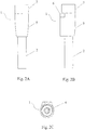
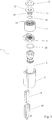
- Figs. 1-3 illustrate a hose nut 1 according to a first example not covered by the claims.
- the hose nut 1 comprises a nut body 3 having a throughbore 4 formed therein.
- the nut body 4 comprises a lower portion 5, a transition portion 6, an upper portion 7 and a magnetic element 8, preferably a flat magnet, mounted on a side of the lower portion 5.
- At least a part, for example an end portion, of the water hose 2 is received in the lower portion.
- the transition portion 6 is immovably secured to the lower portion 5, and the end portion of the water hose 2 is immovably secured to the transition portion 6, both by any one of the common manners in the art, such as threads and snap fit.
- the upper portion 7 for connection to a shower head (not shown) is arranged on the transition portion 6 in such a manner that the upper portion 7 is rotatable relative to the transition portion 6 around an axis 9 of the upper portion 7.
- the manner in which the upper portion 7 is rotatably connected to the transition portion 6 will be described in detail hereinbelow.
- the upper portion 7 has internal threads formed on the inner surface of the throughbore thereof for mating engagement with corresponding threads formed on an outside of the shower head.
- a holding device 10 (see Fig.
- the hose nut 1 of the present invention is slidably attached to the holding device 10 by a magnetic attraction force generated between the magnetic element 8 and the holding device 10.
- the holding device may be made of any material suitable to generate the magnetic attraction with respect to the magnetic element 8.
- the hose nut 1 further comprises a mandrel assembly 11 comprising a top flange 12 and a mandrel 13 extending downwardly from the top flange 12.
- the top flange 12 has a central throughbore formed therein, and the mandrel 13 has a central throughbore axially aligned with the throughbore of the top flange 12.
- the central throughbores of the top flange and the mandrel define a flow bore for water to pass through the mandrel assembly.
- the mandrel assembly 11 is disposed within the throughbore 4 of the nut body 3, with the flow bore of the mandrel assembly in communication with the throughbore of the nut body 3.
- the upper portion 7 of the nut body 3 comprises a shoulder 14 extending inwardly from an inner surface of the throughbore of the upper portion 7.
- the shoulder 14 defines an opening 15 that is configured for allowing passage of the mandrel 13 to be fixed to the transition portion 6 of the nut body 3 but preventing the top flange 12 from passing therethrough, such that the upper portion 7 is rotatable about the mandrel assembly 11 relative to the transition portion 6.
- the opening 15 has a diameter that is larger than a diameter of the mandrel 13 but smaller than an outer diameter of the top flange 12, such that the mandrel 13 is allowed to pass through the opening 15 while the top flange 12 is not.
- the mandrel assembly 11 is fixed to the transition portion 6 by mating engagement between internal threads formed on the inner surface of the throughbore of the transition portion 6 and corresponding threads formed on an outside of the mandrel 13.
- a first O-ring seal 16 is placed between a bottom surface of the top flange 12 of the mandrel assembly 11 and the shoulder 14 of the upper portion 7 of the nut body 3.
- the first O-ring seal 16 is placed around the mandrel 13 of the mandrel assembly 11.
- a second O-ring seal 17 is place between a top surface of the top flange 12 of the mandrel assembly 11 and the shower head, and a third O-ring seal 20 is provided between the end of the water hose 2 and the transition portion 6 of the nut body 3.
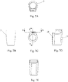
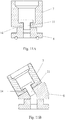
- an undercut portion 18 is formed on the side of the lower portion 5 of the nut body 3 (see Fig. 7D ), and the magnetic element 8 is recessed and embedded in the undercut portion.
- the magnetic element holder 19 is in the shape of a frame comprising a flat surface and two side plates extending from the opposite ends of the flat surface, respectively.
- the flat surface of the holder 19 is flush with an outer surface of the lower portion 5.
- the hose nut 1 and the water hose 2 thus form a water hose assembly 25 for connecting a faucet and a shower head, which can be easily and slidably attached to a holding device mounted on the wall.
- the water hose assembly can be provided as an integral product, that is, with the water hose being integrally formed or prefabricated with the hose nut.
- the second example differs from the first example in two aspects, which will be explained in detail as follows.
- the first difference between the second and the first examples is that, in the first example, the lower portion 5, the transition portion 6 and the upper portion 7 of the nut body 3 are aligned (as best seen in Fig. 3 ), while in the second example, the transition portion 6 is secured at an angle to the lower portion 5 but is aligned with the upper portion 7.
- the throughbore of the transition portion 6 of the second embodiment is formed to comprise a lower segment 21 and an upper segment 22 at an angle with each other.
- the lower segment 21 is aligned with the throughbore of the lower portion 5, while the upper segment 22 is aligned with the throughbore of the upper portion 7.
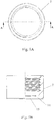
- the second aspect in which the second example differs from the first example is that, in the second example, two magnetic elements 8 are provided and are mounted in parallel on the side of the lower portion 5 of the nut body 3, as shown in Fig. 6 .
- the holder 19 is formed to comprise two compartments for accommodating the two magnetic elements respectively.
- Figs. 12 and 13 illustrate a hose nut according to a third example, not covered by the claims, which differs from the second example only in that the transition portion 6 is accommodated within the lower portion 5, instead of being placed on top of the lower portion 5.
- Such a configuration provides a more compact structure and appearance for the hose nut.
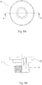
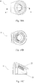
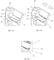
- Figs. 14A-17 illustrate a hose nut according to an embodiment of the present invention, which differs from the third example in that a cover portion 23 extends upwardly from a top of the lower portion 5 to form a one-piece housing 30 of the hose nut, in which housing the upper portion 7, the transition portion 6, the lower portion 5 and other components of the hose nut are all received, resulting in an even more compact structure and aesthetically desirable appearance for the hose nut.
- a locking mechanism is provided to lock the upper portion with the shower head at a desirable angle and prevent the rotation of the upper portion relative to the transition portion around the axis of the upper portion.
- the locking mechanism comprises a button 32, a stopper 33 coupled to the button 32, a pair of posts 34 and a spring 35.
- the stopper is configured to engage with the upper portion thereby creating a lock therebetween for prevention of the rotation of the upper portion when the button is released, and to disengage from the upper portion to allow the rotation of the upper portion when the button is pressed.
- the pair of posts 34 are integrally formed with the holder 19 and extend upwardly from a top of the holder 19 on opposite sides thereof.
- a hole 36 is drilled on each of the posts 34.
- the stopper 33 comprises an arc-shaped portion 37, a leg 38 extending downwardly from each of the two ends of the arc-shaped portion 37, and a pin 39 formed on an outer surface of each of the two legs 38.
- the two pins 39 are inserted into the two holes 36, respectively, such that the stopper 33 is pivotally mounted between the pair of posts 34.
- the stopper 33 further comprises a baffle plate 40 connecting the two ends of the arc-shaped portion 37, which baffle plate abuts against the button 32.
- the button 32 is movably mounted between the pair of posts 34 via a pair of protrusions 41 formed on opposite sides of the button 32 and received in a pair of slits 42 formed on the pair of posts 34, respectively.
- the slits 42 are sized to allow for free movement of the protrusions 41 therein along the length of the slits 42, when the button 32 is pressed or released.
- the length of the slits 42 is long enough to allow the button 32 to push the stopper 33 to completely disengage from the upper portion 7.
- a plurality of teeth 43 are formed on an inner surface of the arc-shaped portion 37 of the stopper 33, which teeth are provided to be able to engage with a plurality of respective recesses 44 formed on a circumference of a bottom of the upper portion 7 to prevent the rotation of the upper portion 7.
- the plurality of teeth 43 are provided in this embodiment to demonstrate the optimal effect of locking the upper portion 7.
- the spring 35 is arranged and compressed under the arc-shaped portion 37 of the stopper 33 to constantly apply an upward force to the stopper 33.
- a depressed portion is formed on a front side of the button 32 to receive the baffle plate 40 of the stopper 33, thereby preventing the stopper 33 from swaying to the left or to the right, and providing a higher stability of the locking mechanism.
- the locking mechanism allows the user to adjust the position of shower head such that the shower head is facing right in front of the user when the shower head is hanged on the magnetic or metallic bar by the magnetic element of the hose nut.
- part of the button extends beyond the one-piece housing 30 through a window formed on the one-piece housing 30, and when the button 32 is fully pressed, an outer surface of it becomes flush with an outer surface of the one-piece housing 30.
- a locking mechanism allows the shower head to be conveniently rotated and to be fixed at a certain desired angle.
- a buffering pad 31 preferably made of rubber materials, is mounted on an outer side surface of the holder, which surface is to be attached to the holding device on the wall for hanging the shower head.
- the buffering pad 31 is provided between the hose nut and the wall, to provide a "soft touch" feeling when mounting the hose nut onto the wall.
- the buffering pad 31 is able to increase the friction between the mounted hose nut and the wall, thus reinforcing the attachment of the hose nut to the wall.
- a hose adaptor 24 is provided and connected to the lower portion 5 of the nut body 3.
- the hose adaptor 24 allows for connection with water hoses of different sizes.
- the structures of the rest of the hose nut are identical to any one of the above embodiments.
- Fig. 19 illustrates a shower system 26 according to a further embodiment of the present invention, which comprises a water hose assembly 25 according to any one of the above embodiments, a shower head 27 connected to the water hose assembly 25 and a holding device 10 mounted on the wall.
- the water hose assembly 25 comprises a hose nut 1 connected to the shower head 27 and a water hose connected to a faucet 28.
- the holding device 10 is provided as a metallic or magnetic bar or panel having a longitudinal slot 29 formed thereon.
- the at least one magnetic element 8 of the hose nut 1 is inserted into the slot 29, and is guided to slide therein as a result of the smooth surface of the slot 29.
- the hose nut 1 is mounted on the holding device 10 and is slidable thereon such that its height can be easily adjusted.
- magnetic attraction forces are utilized to mount the hose nut of the present invention onto the wall, the structure of the hose nut is significantly simplified compared to existing products.
- the weight of the hose nut is substantially reduced, such that the holding device can be mounted onto the wall simply with an adhesive, without the need for fasteners that will cause damage to the wall, such as screws or nails.
Landscapes
- Health & Medical Sciences (AREA)
- Life Sciences & Earth Sciences (AREA)
- Engineering & Computer Science (AREA)
- Hydrology & Water Resources (AREA)
- Public Health (AREA)
- Water Supply & Treatment (AREA)
- Domestic Plumbing Installations (AREA)
Claims (24)
- Schlauchmutter (1) zum Verbinden eines Duschkopfes (27) mit einem Wasserschlauch (2), umfassend einen Mutterkörper (3) mit einer darin ausgebildeten Durchgangsbohrung (4), wobei der Mutterkörper Folgendes umfasst:einen unteren Abschnitt (5) zum Aufnehmen mindestens eines Teils des Wasserschlauchs (2);einen Übergangsabschnitt (6), der unbeweglich am unteren Abschnitt (5) befestigt ist;einen oberen Abschnitt (7) zur Verbindung mit dem Duschkopf (27) und derart am Übergangsabschnitt (6) angeordnet, dass der obere Abschnitt (7) relativ zum Übergangsabschnitt (6) um eine Achse des oberen Abschnitts (9) drehbar ist;mindestens ein an einer Seite des unteren Abschnitts (5) angebrachtes Magnetelement (8), wobei das Magnetelement (8) dazu geeignet ist, durch eine zwischen dem Magnetelement (8) und der Haltevorrichtung (10) erzeugte magnetische Anziehungskraft verschiebbar an einer Haltevorrichtung (10) an einer Wand zum Aufhängen des Duschkopfes (27) an der Wand befestigt zu werden,dadurch gekennzeichnet, dass die Schlauchmutter (1) ferner einen Verriegelungsmechanismus zum Verriegeln des oberen Abschnitts (7) mit dem Duschkopf (27) in einem gewünschten Winkel und zum Verhindern der Drehung des oberen Abschnitts (7) relativ zum Übergangsabschnitt (6) um die Achse des oberen Abschnitts (9) aufweist;wobei der Verriegelungsmechanismus einen Knopf (32) und einen mit dem Knopf (32) gekoppelten Stopper (33) umfasst, wobei der Stopper (33) so konfiguriert ist, dass er mit dem oberen Abschnitt (7) in Eingriff kommt und dadurch eine Verriegelung dazwischen erzeugt, um die Drehung des oberen Abschnitts (7) zu verhindern, wenn der Knopf (32) gelöst ist, und um sich von dem oberen Abschnitt (7) zu lösen, um die Drehung des oberen Abschnitts (7) zu ermöglichen, wenn der Knopf (32) gedrückt wird; undwobei der Stopper (33) mindestens einen Zahn an einer Innenwandfläche davon aufweist, wobei der mindestens eine Zahn (43) in eine von mehreren Aussparungen (44), die in Umfangsrichtung an einer Außenfläche eines Bodens des oberen Abschnitts (7) ausgebildet sind, eingreifen kann, wenn der Knopf (32) gelöst wird, und der mindestens eine Zahn (43) des Stoppers (33) gezwungen wird, sich aus der Aussparung (44) am Boden des oberen Abschnitts (7) zu lösen, wenn der Knopf (32) gedrückt wird.
- Schlauchmutter (1) nach Anspruch 1, die ferner eine Dornanordnung (11) mit einem oberen Flansch (12) mit einer zentralen Durchgangsbohrung und einem Dorn (13) aufweist, der sich von dem oberen Flansch (12) nach unten erstreckt und eine zentrale, axial mit der Durchgangsbohrung des oberen Flansches (12) ausgerichtete Durchgangsbohrung aufweist, um eine Durchflussbohrung für den Durchfluss von Wasser durch die Dornanordnung (11) zu definieren, wobei die Dornanordnung (11) innerhalb der Durchgangsbohrung des Mutterkörpers (3) angeordnet ist, wobei die Durchflussbohrung der Dornanordnung (11) mit der Durchgangsbohrung des Mutterkörpers (3) in Verbindung steht.
- Schlauchmutter (1) nach Anspruch 2, wobei der obere Abschnitt (7) des Mutterkörpers (3) eine Schulter (14) aufweist, die sich von einer Innenfläche der Durchgangsbohrung des oberen Abschnitts (7) nach innen erstreckt, wobei die Schulter (14) eine Öffnung (15) definiert, die so konfiguriert ist, dass sie den Durchgang des an dem Übergangsabschnitt (6) des Mutterkörpers (3) zu befestigenden Dornes (13) erlaubt, aber den oberen Flansch (12) daran hindert, dort hindurchzugehen, so dass der obere Abschnitt (7) um die Dornanordnung (11) relativ zu dem Übergangsabschnitt (6) drehbar ist.
- Schlauchmutter (1) nach Anspruch 3, wobei der Übergangsabschnitt (6) ein Innengewinde aufweist, das an der Innenfläche der Durchgangsbohrung davon für einen Passeingriff mit einem entsprechenden Gewinde ausgebildet ist, das an einer Außenseite des Dorns (13) der Dornanordnung (11) ausgebildet ist.
- Schlauchmutter (1) nach Anspruch 3, wobei eine erste O-Ring-Dichtung (16) zwischen einer unteren Fläche des oberen Flansches (12) der Dornanordnung (11) und der Schulter (14) des oberen Abschnitts (7) des Mutterkörpers (3) angeordnet ist.
- Schlauchmutter (1) nach Anspruch 3, wobei eine zweite O-Ring-Dichtung (17) enthalten ist, die zwischen einer oberen Fläche des oberen Flansches (12) der Dornbaugruppe (11) und dem Duschkopf (27) angeordnet werden kann.
- Schlauchmutter (1) nach einem der Ansprüche 1 bis 6, wobei das mindestens eine magnetische Element (8) in einen hinterschnittenen Abschnitt (18) eingelassen ist, der auf der Seite des unteren Abschnitts (5) des Mutterkörpers (3) ausgebildet ist und von einem Halter (19) gehalten wird, der konfiguriert ist, um zusammen mit einer Oberfläche des hinterschnittenen Abschnitts (18) einen Raum zu definieren, in dem das mindestens eine magnetische Element (8) eingeschlossen ist.
- Schlauchmutter (1) nach Anspruch 7, die ferner ein Pufferkissen (31), vorzugsweise ein Gummikissen, umfasst, das an einer äußeren Seitenfläche des Halters (19) angebracht ist, wobei diese Fläche an der Haltevorrichtung (10) an der Wand zum Aufhängen des Duschkopfes (27) zu befestigen ist; und
wobei das Pufferkissen (31) eine Reibung zwischen der äußeren Seitenfläche des Halters (19) des Magnetelements (8) und der Haltevorrichtung (10) erhöhen kann, um die Bindung dazwischen zu verstärken. - Schlauchmutter (1) nach Anspruch 7 oder 8, wobei der Halter (19) des Magnetelements (8) aus einem Kunststoffmaterial hoher Dichte hergestellt ist, um die magnetische Anziehungskraft zwischen dem Magnetelement (8) und der Haltevorrichtung (10) aufrechtzuerhalten.
- Schlauchmutter (1) nach einem der Ansprüche 7 bis 9, wobei der Halter (19) zum Halten des mindestens einen magnetischen Elements (8) so vorgesehen ist, dass er mit einer Außenfläche des unteren Abschnitts (5) des Mutterkörpers (3) bündig ist.
- Schlauchmutter (1) nach einem der Ansprüche 1 bis 10, wobei der Übergangsabschnitt (6) in dem unteren Abschnitt (5) untergebracht ist.
- Schlauchmutter (1) nach einem der Ansprüche 1 bis 11, wobei sich ein Abdeckabschnitt (23) von einer Oberseite des unteren Abschnitts (5) nach oben erstreckt, um ein einstückiges Gehäuse (30) der Schlauchmutter (1) zu bilden, und wobei der obere Abschnitt (7) in dem Abdeckabschnitt (23) untergebracht ist.
- Schlauchmutter (1) nach einem der Ansprüche 1 bis 12, wobei der untere Abschnitt (5), der Übergangsabschnitt (6) und der obere Abschnitt (7) des Mutterkörpers (3) so vorgesehen sind, dass der Übergangsabschnitt (6) in einem Winkel zum unteren Abschnitt (5) befestigt ist, aber mit dem oberen Abschnitt (7) ausgerichtet ist; oder wobei
der untere Abschnitt (5), der Übergangsabschnitt (6) und der obere Abschnitt (7) des Mutterkörpers (3) aufeinander ausgerichtet sind. - Schlauchmutter (1) nach einem der Ansprüche 1 bis 13, wobei der obere Abschnitt (7) ein Innengewinde aufweist, das an der Innenfläche seiner Durchgangsbohrung (4) für einen Passeingriff mit einem entsprechenden Gewinde ausgebildet ist, das an einer Außenseite des Duschkopfes (27) ausgebildet ist, oder wobei der obere Abschnitt (7) geeignet ist, mit dem Duschkopf (27) durch eine Schnappverbindung verbunden zu werden.
- Schlauchmutter (1) nach einem der Ansprüche 1 bis 14, die ferner einen Schlauchadapter (24) umfasst, der mit dem unteren Abschnitt (5) des Mutterkörpers (3) verbunden ist und die Verbindung der Schlauchmutter (1) an verschiedene Wasserschläuche ermöglicht.
- Schlauchmutter (1) nach einem der Ansprüche 1 bis 15, wobei eine dritte O-Ring-Dichtung (20) enthalten ist, die geeignet ist, zwischen der Schlauchmutter (1) und dem Wasserschlauch (2) vorgesehen zu werden.
- Schlauchmutter (1) nach einem der Ansprüche 1 bis 16, wobei sich ein Paar von Pfosten (34) von einer Oberseite des Halters (19) nach oben erstreckt und der Stopper (33) schwenkbar zwischen dem Paar von Pfosten (34) derart angebracht ist, dass, wenn der Knopf (32) gedrückt ist, der Stopper (33) durch den Knopf (32) gezwungen wird, nach unten zu schwenken, wodurch der mindestens eine Zahn (43) des Stoppers (33) aus der Aussparung (44) am Boden des oberen Abschnitts (7) gelöst wird.
- Schlauchmutter (1) nach Anspruch 17, wobei der Stopper (33) einen bogenförmigen Abschnitt (37) aufweist, der unter dem oberen Abschnitt (7) angeordnet ist, und der mindestens eine Zahn (43) an einer Innenfläche des bogenförmigen Abschnitts (37) ausgebildet ist.
- Schlauchmutter (1) nach Anspruch 18, wobei der Verriegelungsmechanismus ferner eine Feder (35) umfasst, die unter dem Stopper (33) zusammengedrückt ist, um ständig eine nach oben gerichtete Kraft auf den Stopper (33) auszuüben, so dass, wenn der Knopf (32) gelöst ist, der Stopper (33) durch die Feder (35) gezwungen wird, nach oben zu schwenken, wodurch der mindestens eine Zahn (43) des Stoppers (33) in die Aussparung (44) am Boden des oberen Abschnitts (7) eingreift.
- Wasserschlauchanordnung (25) zum Verbinden eines Wasserhahns (28) und eines Duschkopfes (27), umfassend einen Wasserschlauch (2) und eine Schlauchmutter (1) nach einem der Ansprüche 1 bis 19, wobei die Schlauchmutter (1) und der Wasserschlauch (2) einstückig vorgefertigt sind.
- Duschsystem (26), das Folgendes umfasst:eine Wasserschlauchanordnung (25) nach Anspruch 20,einen Duschkopf (27) undeine an einer Wand angebrachte Haltevorrichtung (10) zum Aufhängen des Duschkopfes (27) an der Wand durch eine zwischen dem Magnetelement (8) und der Haltevorrichtung (10) erzeugte magnetische Anziehungskraft.
- Duschsystem (26) nach Anspruch 21, wobei die Haltevorrichtung (10) als eine metallische oder magnetische Stange oder als eine metallische oder magnetische Platte vorgesehen ist, so dass die Schlauchmutter (1) an der Stange oder dem Paneel in verschiedenen Höhen der Wand oder an verschiedenen Positionen der Wand verschiebbar befestigt werden kann.
- Duschsystem (26) nach Anspruch 22, wobei die Stange oder die Platte an der Wand mit einem Klebemittel angebracht ist.
- Duschsystem (26) nach Anspruch 22 oder 23, wobei die Stange einen Längsschlitz (29) aufweist, in den das mindestens eine magnetische Element (8) der Schlauchmutter (1) eingesetzt ist, wodurch die Schlauchmutter (1) in dem Schlitz (29) gleitend geführt wird.
Applications Claiming Priority (2)
| Application Number | Priority Date | Filing Date | Title |
|---|---|---|---|
| US201462003629P | 2014-05-28 | 2014-05-28 | |
| DE202015101159.8U DE202015101159U1 (de) | 2014-05-28 | 2015-03-09 | Schlauchmutter, Wasserschlauchanordnung aufweisend die Schlauchmutter und Duschsystem aufweisend die Wasserschlauchanordnung |
Publications (2)
| Publication Number | Publication Date |
|---|---|
| EP2949824A1 EP2949824A1 (de) | 2015-12-02 |
| EP2949824B1 true EP2949824B1 (de) | 2020-11-04 |
Family
ID=52987994
Family Applications (1)
| Application Number | Title | Priority Date | Filing Date |
|---|---|---|---|
| EP15275065.9A Not-in-force EP2949824B1 (de) | 2014-05-28 | 2015-03-13 | Schlauchmutter, wasserschlauchanordnung mit der schlauchmutter und duschsystem mit der wasserschlauchanordnung |
Country Status (1)
| Country | Link |
|---|---|
| EP (1) | EP2949824B1 (de) |
Family Cites Families (6)
| Publication number | Priority date | Publication date | Assignee | Title |
|---|---|---|---|---|
| KR920007495Y1 (ko) * | 1989-10-14 | 1992-10-15 | 아메리칸스탠다아드 인코포레이팃드 | 욕실용 샤워헤드 연결구 |
| DE9300418U1 (de) * | 1993-01-11 | 1993-03-25 | Korhammer, Bernd, 4290 Bocholt | Duschvorrichtung |
| DE10030644A1 (de) * | 2000-06-29 | 2002-01-10 | Grohe Armaturen Friedrich | Handbrause |
| DE102006056511A1 (de) * | 2006-11-30 | 2008-06-05 | Fischerwerke Gmbh & Co. Kg | Führungseinrichtung und Vorrichtung mit Führungseinrichtung |
| GB0715624D0 (en) * | 2007-08-08 | 2007-09-19 | Kohler Daryl Ltd | Magnetically repositionable showerhead mounting |
| KR20120035521A (ko) * | 2010-10-05 | 2012-04-16 | 김강환 | 샤워기 헤드 높낮이 조절장치 |
-
2015
- 2015-03-13 EP EP15275065.9A patent/EP2949824B1/de not_active Not-in-force
Non-Patent Citations (1)
| Title |
|---|
| None * |
Also Published As
| Publication number | Publication date |
|---|---|
| EP2949824A1 (de) | 2015-12-02 |
Similar Documents
| Publication | Publication Date | Title |
|---|---|---|
| US9822512B2 (en) | Hose nut, water hose assembly comprising the hose nut and shower system comprising the water hose assembly | |
| US9551367B1 (en) | Structure of back clip of tool box | |
| CN205063531U (zh) | 用于门手柄和/或窗手柄的止挡体 | |
| EP2865816B1 (de) | Gewichtsanordnung für eine Mischarmatur umfassend einen ausziehbarem Schlauch mit einem Duschkopf | |
| US9963932B2 (en) | Safety gate and locking device for the same | |
| EP2593703B1 (de) | Schelle für eine rohranordnung, einrastvorrichtung für die schelle und rohranordnung mit der schelle | |
| EP2803305A1 (de) | Türanordnung | |
| EP3910204B1 (de) | Möbeln und anderen einrichtungsgegenständen mit kompaktem verbindungsstück zur verbindung einer ersten und einer zweiten platte | |
| US9915088B2 (en) | Door stop assembly with decorative member | |
| CN114206162A (zh) | 家具搁板的支撑装置 | |
| EP1688569A1 (de) | Schnappscharnier zur halterung von schliesselementen | |
| CN112930447B (zh) | 家具或其它家具用品的肩部和搁板之间的接头的改进的驱动和阻挡系统 | |
| CA2885447A1 (en) | Installation body for door and/or window handles and handle arrangement with one installation body | |
| US6112801A (en) | Pendant finial | |
| HK1217523B (en) | Hose nut, water hose assembly comprising the hose nut and shower system comprising the water hose assembly | |
| EP2949824A1 (de) | Schlauchmutter, wasserschlauchanordnung mit der schlauchmutter und duschsystem mit der wasserschlauchanordnung | |
| CA2876212C (en) | Hook device for hanging objects | |
| HK1217523A1 (en) | Hose nut, water hose assembly comprising the hose nut and shower system comprising the water hose assembly | |
| AU2015267876B2 (en) | Hose nut, water hose assembly comprising hose nut and shower system comprising water hose assembly | |
| US10954980B2 (en) | Connection fitting | |
| EP3271634A1 (de) | Verriegelungsanordnung für eine leuchte | |
| CN221722564U (zh) | 反弹器 | |
| EP1750021A1 (de) | Einstellbare Befestigungsvorrichtung, insbesondere zur Wandbefestigung einer Sanitäranlagestruktur | |
| EP3348716A1 (de) | Tragevorrichtung für einen duschkopf | |
| EP2891437A1 (de) | Verstellbarer Duschrahmen lösbar an einer Wand durch einen Riegelschieber |
Legal Events
| Date | Code | Title | Description |
|---|---|---|---|
| AK | Designated contracting states |
Kind code of ref document: A1 Designated state(s): AL AT BE BG CH CY CZ DE DK EE ES FI FR GB GR HR HU IE IS IT LI LT LU LV MC MK MT NL NO PL PT RO RS SE SI SK SM TR |
|
| AX | Request for extension of the european patent |
Extension state: BA ME |
|
| PUAI | Public reference made under article 153(3) epc to a published international application that has entered the european phase |
Free format text: ORIGINAL CODE: 0009012 |
|
| 17P | Request for examination filed |
Effective date: 20160602 |
|
| RBV | Designated contracting states (corrected) |
Designated state(s): AL AT BE BG CH CY CZ DE DK EE ES FI FR GB GR HR HU IE IS IT LI LT LU LV MC MK MT NL NO PL PT RO RS SE SI SK SM TR |
|
| REG | Reference to a national code |
Ref country code: HK Ref legal event code: DE Ref document number: 1217523 Country of ref document: HK |
|
| GRAP | Despatch of communication of intention to grant a patent |
Free format text: ORIGINAL CODE: EPIDOSNIGR1 |
|
| STAA | Information on the status of an ep patent application or granted ep patent |
Free format text: STATUS: GRANT OF PATENT IS INTENDED |
|
| INTG | Intention to grant announced |
Effective date: 20190513 |
|
| GRAS | Grant fee paid |
Free format text: ORIGINAL CODE: EPIDOSNIGR3 |
|
| GRAA | (expected) grant |
Free format text: ORIGINAL CODE: 0009210 |
|
| STAA | Information on the status of an ep patent application or granted ep patent |
Free format text: STATUS: THE PATENT HAS BEEN GRANTED |
|
| AK | Designated contracting states |
Kind code of ref document: B1 Designated state(s): AL AT BE BG CH CY CZ DE DK EE ES FI FR GB GR HR HU IE IS IT LI LT LU LV MC MK MT NL NO PL PT RO RS SE SI SK SM TR |
|
| REG | Reference to a national code |
Ref country code: GB Ref legal event code: FG4D |
|
| REG | Reference to a national code |
Ref country code: CH Ref legal event code: EP |
|
| REG | Reference to a national code |
Ref country code: AT Ref legal event code: REF Ref document number: 1330992 Country of ref document: AT Kind code of ref document: T Effective date: 20201115 |
|
| REG | Reference to a national code |
Ref country code: IE Ref legal event code: FG4D |
|
| REG | Reference to a national code |
Ref country code: DE Ref legal event code: R096 Ref document number: 602015061429 Country of ref document: DE |
|
| REG | Reference to a national code |
Ref country code: NL Ref legal event code: MP Effective date: 20201104 |
|
| REG | Reference to a national code |
Ref country code: AT Ref legal event code: MK05 Ref document number: 1330992 Country of ref document: AT Kind code of ref document: T Effective date: 20201104 |
|
| PG25 | Lapsed in a contracting state [announced via postgrant information from national office to epo] |
Ref country code: NO Free format text: LAPSE BECAUSE OF FAILURE TO SUBMIT A TRANSLATION OF THE DESCRIPTION OR TO PAY THE FEE WITHIN THE PRESCRIBED TIME-LIMIT Effective date: 20210204 Ref country code: PT Free format text: LAPSE BECAUSE OF FAILURE TO SUBMIT A TRANSLATION OF THE DESCRIPTION OR TO PAY THE FEE WITHIN THE PRESCRIBED TIME-LIMIT Effective date: 20210304 Ref country code: RS Free format text: LAPSE BECAUSE OF FAILURE TO SUBMIT A TRANSLATION OF THE DESCRIPTION OR TO PAY THE FEE WITHIN THE PRESCRIBED TIME-LIMIT Effective date: 20201104 Ref country code: FI Free format text: LAPSE BECAUSE OF FAILURE TO SUBMIT A TRANSLATION OF THE DESCRIPTION OR TO PAY THE FEE WITHIN THE PRESCRIBED TIME-LIMIT Effective date: 20201104 Ref country code: GR Free format text: LAPSE BECAUSE OF FAILURE TO SUBMIT A TRANSLATION OF THE DESCRIPTION OR TO PAY THE FEE WITHIN THE PRESCRIBED TIME-LIMIT Effective date: 20210205 |
|
| PGFP | Annual fee paid to national office [announced via postgrant information from national office to epo] |
Ref country code: FR Payment date: 20210331 Year of fee payment: 7 |
|
| PG25 | Lapsed in a contracting state [announced via postgrant information from national office to epo] |
Ref country code: PL Free format text: LAPSE BECAUSE OF FAILURE TO SUBMIT A TRANSLATION OF THE DESCRIPTION OR TO PAY THE FEE WITHIN THE PRESCRIBED TIME-LIMIT Effective date: 20201104 Ref country code: IS Free format text: LAPSE BECAUSE OF FAILURE TO SUBMIT A TRANSLATION OF THE DESCRIPTION OR TO PAY THE FEE WITHIN THE PRESCRIBED TIME-LIMIT Effective date: 20210304 Ref country code: SE Free format text: LAPSE BECAUSE OF FAILURE TO SUBMIT A TRANSLATION OF THE DESCRIPTION OR TO PAY THE FEE WITHIN THE PRESCRIBED TIME-LIMIT Effective date: 20201104 Ref country code: LV Free format text: LAPSE BECAUSE OF FAILURE TO SUBMIT A TRANSLATION OF THE DESCRIPTION OR TO PAY THE FEE WITHIN THE PRESCRIBED TIME-LIMIT Effective date: 20201104 Ref country code: AT Free format text: LAPSE BECAUSE OF FAILURE TO SUBMIT A TRANSLATION OF THE DESCRIPTION OR TO PAY THE FEE WITHIN THE PRESCRIBED TIME-LIMIT Effective date: 20201104 Ref country code: ES Free format text: LAPSE BECAUSE OF FAILURE TO SUBMIT A TRANSLATION OF THE DESCRIPTION OR TO PAY THE FEE WITHIN THE PRESCRIBED TIME-LIMIT Effective date: 20201104 Ref country code: BG Free format text: LAPSE BECAUSE OF FAILURE TO SUBMIT A TRANSLATION OF THE DESCRIPTION OR TO PAY THE FEE WITHIN THE PRESCRIBED TIME-LIMIT Effective date: 20210204 |
|
| REG | Reference to a national code |
Ref country code: LT Ref legal event code: MG9D |
|
| PG25 | Lapsed in a contracting state [announced via postgrant information from national office to epo] |
Ref country code: HR Free format text: LAPSE BECAUSE OF FAILURE TO SUBMIT A TRANSLATION OF THE DESCRIPTION OR TO PAY THE FEE WITHIN THE PRESCRIBED TIME-LIMIT Effective date: 20201104 |
|
| PG25 | Lapsed in a contracting state [announced via postgrant information from national office to epo] |
Ref country code: SK Free format text: LAPSE BECAUSE OF FAILURE TO SUBMIT A TRANSLATION OF THE DESCRIPTION OR TO PAY THE FEE WITHIN THE PRESCRIBED TIME-LIMIT Effective date: 20201104 Ref country code: RO Free format text: LAPSE BECAUSE OF FAILURE TO SUBMIT A TRANSLATION OF THE DESCRIPTION OR TO PAY THE FEE WITHIN THE PRESCRIBED TIME-LIMIT Effective date: 20201104 Ref country code: LT Free format text: LAPSE BECAUSE OF FAILURE TO SUBMIT A TRANSLATION OF THE DESCRIPTION OR TO PAY THE FEE WITHIN THE PRESCRIBED TIME-LIMIT Effective date: 20201104 Ref country code: SM Free format text: LAPSE BECAUSE OF FAILURE TO SUBMIT A TRANSLATION OF THE DESCRIPTION OR TO PAY THE FEE WITHIN THE PRESCRIBED TIME-LIMIT Effective date: 20201104 Ref country code: EE Free format text: LAPSE BECAUSE OF FAILURE TO SUBMIT A TRANSLATION OF THE DESCRIPTION OR TO PAY THE FEE WITHIN THE PRESCRIBED TIME-LIMIT Effective date: 20201104 Ref country code: CZ Free format text: LAPSE BECAUSE OF FAILURE TO SUBMIT A TRANSLATION OF THE DESCRIPTION OR TO PAY THE FEE WITHIN THE PRESCRIBED TIME-LIMIT Effective date: 20201104 |
|
| PGFP | Annual fee paid to national office [announced via postgrant information from national office to epo] |
Ref country code: DE Payment date: 20210421 Year of fee payment: 7 |
|
| REG | Reference to a national code |
Ref country code: DE Ref legal event code: R097 Ref document number: 602015061429 Country of ref document: DE |
|
| PG25 | Lapsed in a contracting state [announced via postgrant information from national office to epo] |
Ref country code: DK Free format text: LAPSE BECAUSE OF FAILURE TO SUBMIT A TRANSLATION OF THE DESCRIPTION OR TO PAY THE FEE WITHIN THE PRESCRIBED TIME-LIMIT Effective date: 20201104 |
|
| PGFP | Annual fee paid to national office [announced via postgrant information from national office to epo] |
Ref country code: GB Payment date: 20210422 Year of fee payment: 7 |
|
| PLBE | No opposition filed within time limit |
Free format text: ORIGINAL CODE: 0009261 |
|
| STAA | Information on the status of an ep patent application or granted ep patent |
Free format text: STATUS: NO OPPOSITION FILED WITHIN TIME LIMIT |
|
| 26N | No opposition filed |
Effective date: 20210805 |
|
| PG25 | Lapsed in a contracting state [announced via postgrant information from national office to epo] |
Ref country code: AL Free format text: LAPSE BECAUSE OF FAILURE TO SUBMIT A TRANSLATION OF THE DESCRIPTION OR TO PAY THE FEE WITHIN THE PRESCRIBED TIME-LIMIT Effective date: 20201104 Ref country code: IT Free format text: LAPSE BECAUSE OF FAILURE TO SUBMIT A TRANSLATION OF THE DESCRIPTION OR TO PAY THE FEE WITHIN THE PRESCRIBED TIME-LIMIT Effective date: 20201104 Ref country code: MC Free format text: LAPSE BECAUSE OF FAILURE TO SUBMIT A TRANSLATION OF THE DESCRIPTION OR TO PAY THE FEE WITHIN THE PRESCRIBED TIME-LIMIT Effective date: 20201104 Ref country code: NL Free format text: LAPSE BECAUSE OF FAILURE TO SUBMIT A TRANSLATION OF THE DESCRIPTION OR TO PAY THE FEE WITHIN THE PRESCRIBED TIME-LIMIT Effective date: 20201104 |
|
| REG | Reference to a national code |
Ref country code: CH Ref legal event code: PL |
|
| PG25 | Lapsed in a contracting state [announced via postgrant information from national office to epo] |
Ref country code: SI Free format text: LAPSE BECAUSE OF FAILURE TO SUBMIT A TRANSLATION OF THE DESCRIPTION OR TO PAY THE FEE WITHIN THE PRESCRIBED TIME-LIMIT Effective date: 20201104 |
|
| REG | Reference to a national code |
Ref country code: BE Ref legal event code: MM Effective date: 20210331 |
|
| PG25 | Lapsed in a contracting state [announced via postgrant information from national office to epo] |
Ref country code: CH Free format text: LAPSE BECAUSE OF NON-PAYMENT OF DUE FEES Effective date: 20210331 Ref country code: LU Free format text: LAPSE BECAUSE OF NON-PAYMENT OF DUE FEES Effective date: 20210313 Ref country code: LI Free format text: LAPSE BECAUSE OF NON-PAYMENT OF DUE FEES Effective date: 20210331 Ref country code: IE Free format text: LAPSE BECAUSE OF NON-PAYMENT OF DUE FEES Effective date: 20210313 |
|
| PG25 | Lapsed in a contracting state [announced via postgrant information from national office to epo] |
Ref country code: IS Free format text: LAPSE BECAUSE OF FAILURE TO SUBMIT A TRANSLATION OF THE DESCRIPTION OR TO PAY THE FEE WITHIN THE PRESCRIBED TIME-LIMIT Effective date: 20210304 |
|
| PG25 | Lapsed in a contracting state [announced via postgrant information from national office to epo] |
Ref country code: BE Free format text: LAPSE BECAUSE OF NON-PAYMENT OF DUE FEES Effective date: 20210331 |
|
| REG | Reference to a national code |
Ref country code: DE Ref legal event code: R119 Ref document number: 602015061429 Country of ref document: DE |
|
| GBPC | Gb: european patent ceased through non-payment of renewal fee |
Effective date: 20220313 |
|
| PG25 | Lapsed in a contracting state [announced via postgrant information from national office to epo] |
Ref country code: GB Free format text: LAPSE BECAUSE OF NON-PAYMENT OF DUE FEES Effective date: 20220313 Ref country code: FR Free format text: LAPSE BECAUSE OF NON-PAYMENT OF DUE FEES Effective date: 20220331 Ref country code: DE Free format text: LAPSE BECAUSE OF NON-PAYMENT OF DUE FEES Effective date: 20221001 |
|
| PG25 | Lapsed in a contracting state [announced via postgrant information from national office to epo] |
Ref country code: HU Free format text: LAPSE BECAUSE OF FAILURE TO SUBMIT A TRANSLATION OF THE DESCRIPTION OR TO PAY THE FEE WITHIN THE PRESCRIBED TIME-LIMIT; INVALID AB INITIO Effective date: 20150313 |
|
| PG25 | Lapsed in a contracting state [announced via postgrant information from national office to epo] |
Ref country code: CY Free format text: LAPSE BECAUSE OF FAILURE TO SUBMIT A TRANSLATION OF THE DESCRIPTION OR TO PAY THE FEE WITHIN THE PRESCRIBED TIME-LIMIT Effective date: 20201104 |
|
| PG25 | Lapsed in a contracting state [announced via postgrant information from national office to epo] |
Ref country code: MK Free format text: LAPSE BECAUSE OF FAILURE TO SUBMIT A TRANSLATION OF THE DESCRIPTION OR TO PAY THE FEE WITHIN THE PRESCRIBED TIME-LIMIT Effective date: 20201104 |
|
| PG25 | Lapsed in a contracting state [announced via postgrant information from national office to epo] |
Ref country code: TR Free format text: LAPSE BECAUSE OF FAILURE TO SUBMIT A TRANSLATION OF THE DESCRIPTION OR TO PAY THE FEE WITHIN THE PRESCRIBED TIME-LIMIT Effective date: 20201104 |
|
| PG25 | Lapsed in a contracting state [announced via postgrant information from national office to epo] |
Ref country code: MT Free format text: LAPSE BECAUSE OF FAILURE TO SUBMIT A TRANSLATION OF THE DESCRIPTION OR TO PAY THE FEE WITHIN THE PRESCRIBED TIME-LIMIT Effective date: 20201104 |