EP2949825A1 - Verbesserte doppelsteuerungsmodusartige desodorierung und wasserablaufventil - Google Patents
Verbesserte doppelsteuerungsmodusartige desodorierung und wasserablaufventil Download PDFInfo
- Publication number
- EP2949825A1 EP2949825A1 EP14743266.0A EP14743266A EP2949825A1 EP 2949825 A1 EP2949825 A1 EP 2949825A1 EP 14743266 A EP14743266 A EP 14743266A EP 2949825 A1 EP2949825 A1 EP 2949825A1
- Authority
- EP
- European Patent Office
- Prior art keywords
- odor removal
- water drainage
- piston
- venting pipe
- removal system
- Prior art date
- Legal status (The legal status is an assumption and is not a legal conclusion. Google has not performed a legal analysis and makes no representation as to the accuracy of the status listed.)
- Granted
Links
Images





Classifications
-
- E—FIXED CONSTRUCTIONS
- E03—WATER SUPPLY; SEWERAGE
- E03D—WATER-CLOSETS OR URINALS WITH FLUSHING DEVICES; FLUSHING VALVES THEREFOR
- E03D9/00—Sanitary or other accessories for lavatories ; Devices for cleaning or disinfecting the toilet room or the toilet bowl; Devices for eliminating smells
- E03D9/04—Special arrangement or operation of ventilating devices
- E03D9/05—Special arrangement or operation of ventilating devices ventilating the bowl
- E03D9/052—Special arrangement or operation of ventilating devices ventilating the bowl using incorporated fans
-
- E—FIXED CONSTRUCTIONS
- E03—WATER SUPPLY; SEWERAGE
- E03D—WATER-CLOSETS OR URINALS WITH FLUSHING DEVICES; FLUSHING VALVES THEREFOR
- E03D1/00—Water flushing devices with cisterns ; Setting up a range of flushing devices or water-closets; Combinations of several flushing devices
- E03D1/30—Valves for high or low level cisterns; Their arrangement ; Flushing mechanisms in the cistern, optionally with provisions for a pre-or a post- flushing and for cutting off the flushing mechanism in case of leakage
- E03D1/302—Valves for high or low level cisterns; Their arrangement ; Flushing mechanisms in the cistern, optionally with provisions for a pre-or a post- flushing and for cutting off the flushing mechanism in case of leakage with valves kept in open position by means of air or water pressure or by vacuum
-
- E—FIXED CONSTRUCTIONS
- E03—WATER SUPPLY; SEWERAGE
- E03D—WATER-CLOSETS OR URINALS WITH FLUSHING DEVICES; FLUSHING VALVES THEREFOR
- E03D1/00—Water flushing devices with cisterns ; Setting up a range of flushing devices or water-closets; Combinations of several flushing devices
- E03D1/30—Valves for high or low level cisterns; Their arrangement ; Flushing mechanisms in the cistern, optionally with provisions for a pre-or a post- flushing and for cutting off the flushing mechanism in case of leakage
- E03D1/34—Flushing valves for outlets; Arrangement of outlet valves
Definitions
- the invention relates to sanitary fixtures and more particularly to a flush valve adapted to activate to remove toilet odor by activating one of a linear control water drainage mechanism and a hydraulic water drainage mechanism.
- Chinese Patent No. ZL201110001526.8 discloses a device adapted to mount in a toilet for odor removal.
- the device comprises an odor exhaust unit, a flush system, an overflow assembly, and a water inlet system.
- the patent has advantages of excellent odor removal, adaptability, and being configured to modify.
- the patent also has following disadvantages because it adopts tap water and pressure as means for flushing: Flush valve and inlet valve are co-activated by a hydraulic switch.
- An inlet filter can be partially or completely blocked after one to two years of use if quality of tap water is not good. It can greatly decrease water pressure.
- the flush capability of the toilet can be compromised due to low water pressure.
- the amount of water per flushing is subject to water pressure because the flush valve is activated by tap water. This is disadvantageous to water saving toilets. Water stored in the toilet tank cannot be used to for flushing if the supply of tap water is cut off. This is because there is no activation of the device. Finally, there are excessive components which are difficult
- the flush valve has the advantages of simple components, superior adaptability, high efficiency, and eliminating odor after discharging feces.
- an odor removal system for removing odor from a toilet, comprising a flush valve disposed in a toilet tank, the flush valve including a valve base; a linear control water drainage mechanism disposed above the valve base; and a hydraulic water drainage mechanism disposed above the valve base; characterized by the linear control water drainage mechanism includes a piston and a central partition plate for forming a piston chamber in an upper portion of the piston, the piston chamber configured to accommodate reciprocation of the piston, and a water drainage fluid chamber for flushing in a lower portion of the piston, the water drainage fluid chamber for flushing configured to apply water pressure to the piston; and the hydraulic water drainage mechanism includes a micro-immersible pump including an inlet communicating with a reservoir which communicates with the toilet tank through a filter, and an outlet communicating with the water drainage fluid chamber for flushing.
- the central partition plate includes a plurality of through holes for communicating the piston chamber with the water drainage fluid chamber for flushing, and wherein a sum of areas of cross sections of the through holes is not greater than 15 mm 2 .
- a biasing member in the piston chamber biasing against the central partition plate, and a rope having a first end connected to the piston.
- a venting pipe extending from the valve base, and a waterproof spiral staircase disposed in the venting pipe, the spiral staircase including a plurality of step members equally spaced along an axis thereof.
- an odor removal device communicating with the valve base via a venting pipe, the odor removal device including a fan coaxial with the venting pipe and communicating therewith, an outlet member, and an odor removal medium.
- the odor removal medium is a high pressure ozone ceramic member controlled by an ozone generation control circuit.
- the odor removal medium is a mesh plate coated with catalyst, the mesh plate disposed in the outlet member.
- the flush valve is adapted to activate to remove toilet odor by activating one of the linear control water drainage mechanism and the hydraulic water drainage mechanism. It is understood that odor may exist in the lower chamber between flushing and an immediate next water refill and the remaining odor is adverse to provide a precise amount of water for flushing.
- the provision of the through holes in the central partition plate allows odor in the water drainage fluid chamber for flushing flowing to the piston chamber. As such, the water drainage fluid chamber for flushing is a vacuum, thereby precisely providing the desired amount of water for flushing. Variation of the amount of water for flushing is decreased to a minimum. A constant amount of water for flushing can be carried out with adverse factors of the environment being substantially eliminated. It is highly reliable. Its useful life is prolonged.
- the waterproof spiral staircase provided in the venting pipe can prevent water from drawing into the odor removal device when flushing. Otherwise, the odor removal device may malfunction.
- the odor removal medium in the odor removal device can effectively remove noxious vapors from the toilet.
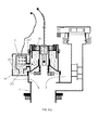
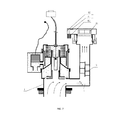
- a flush valve for removing toilet odor in accordance with the invention is disposed in a toilet tank.
- the flush valve includes a valve base 1.
- a linear control water drainage mechanism 2 and a hydraulic water drainage mechanism 3.
- the valve base 1 is in communication with a toilet. Both the linear control water drainage mechanism 2 and the hydraulic water drainage mechanism 3 are disposed above the valve base 1.
- the linear control water drainage mechanism 2 includes a hollow body, a piston 21 slidably disposed in the body, and a sealing rubber 22 under the piston 21 for sealing the valve base 1.
- a central partition plate 211 in the piston 21 separates space in the piston 21 into upper and lower chambers.
- at least one through hole 2111 is provided in the central partition plate 211 for communicating the upper chamber with the lower chamber or vise versa.
- the number, shape, and location of the through hole 2111 is not limited as long as it is provided in the central partition plate 211.
- the sum of areas of cross sections of all through holes 2111 is not greater than 15 mm 2 .
- the provision of the through holes 2111 is to communicate the upper chamber with the lower chamber or vise versa so that the following advantages can be achieved: Odor can be completely expelled out of the lower chamber between flushing and an immediate next water refill. A precise amount of water for flushing can be controlled. A stable water supply for flushing can be achieved. Variation of the amount of water for flushing is decreased to a minimum. Adverse effect of external factors is decreased to a minimum. The purpose of controlling the sum of areas of cross sections of all through holes 2111 is to keep water pressure in the lower chamber at an optimum range.
- a piston chamber 23 is provided in the upper chamber for accommodating the reciprocation of the piston 21.
- a water drainage fluid chamber 24 for flushing is provided in the lower chamber for exerting water pressure to the piston 21.
- the water drainage fluid chamber 24 for flushing communicates with the piston chamber 23 via the through hole 2111.
- the provision of at least one through hole 2111 is required. Odor may exist in the lower chamber between flushing and an immediate next water refill and the odor is adverse to provide a precise amount of water for flushing if there is no through hole through the central partition plate 211. That is, variation of the amount of water for flushing is great.
- the provision of the through holes 2111 allows the odor in the water drainage fluid chamber 24 for flushing flowing to the piston chamber 23 via the through holes 2111.
- the water drainage fluid chamber 24 for flushing is a vacuum, thereby precisely providing the desired amount of water for flushing. Variation of the amount of water for flushing is decreased to a minimum. A constant amount of water for flushing can be carried out with adverse factors of the environment being substantially eliminated.
- a torsion spring 25 biasing against the central partition plate 211.
- the torsion spring 25 can push the piston 21 to move downward when the water pressure does not exist or any external pushing and pulling force is removed.
- the sealing rubber 22 under the piston 21 can seal an outlet 4 on top of the valve base 1. As a result, a single flushing is finished.
- the linear control water drainage mechanism 2 includes a rope (e.g., steel rope) 26 having one end connected to a controller 5 and the other end connected to a metal block 261 in a chamber member 27 which is disposed above the central partition plate 211.
- An annular sliding member 212 disposed externally of the central partition plate 211 is slidably mounted onto an inner surface of the body.
- a piston rubber 213 is provided on a lower portion of an outer surface of the sliding member 212 for sealing the water drainage fluid chamber 24 for flushing.
- the piston 21 can move upward in response to water pressure applied thereto.
- the hydraulic water drainage mechanism 3 includes a micro-immersible pump 31 activated by a sunken pump controller 6, the micro-immersible pump 31 having an inlet 311 in communication with a reservoir 28 having a filter 281.
- the reservoir 28 communicates with the toilet tank through the filter 281 to ensure water stored in the reservoir 28 is filtered. Otherwise, impurities in the water may accumulate to cause the micro-immersible pump 31 to malfunction.
- An outlet 312 of the micro-immersible pump 31 communicates with the water drainage fluid chamber 24 for flushing.
- the outlet 4 above the valve base 1 is sealed by the sealing rubber 22 under the piston 21.
- a person may pull the rope 26 to lift the metal block 261 and thus the piston 21. And in turn, the piston 21 moves upward with the torsion spring 25 compressed. As such, the water in the reservoir 28 flows out of the outlet 4 to flush the feces in the toilet.
- the person may activate the micro-immersible pump 31 to draw water in the reservoir 28 into the water drainage fluid chamber 24 for flushing through the outlet 312 of the micro-immersible pump 31.
- Water pressure is built immediately in the water drainage fluid chamber 24 for flushing to lift the piston 21 with the torsion spring 25 compressed. As such, the water in the reservoir 28 flows out of the outlet 4 to flush the feces in the toilet.
- a venting pipe 7 communicates the outlet 4 with an odor removal device 8.
- a waterproof spiral staircase 9 is provided in the venting pipe 7 for preventing water from drawing into the odor removal device 8 when flushing.
- the waterproof spiral staircase 9 includes a plurality of wedge shaped step members 91 equally spaced along an axis thereof.
- the odor removal device 8 includes an odor removal medium (not shown), a fan 81 coaxial with the venting pipe 7 and communicating therewith, an outlet 82 in a housing, a mesh plate (not shown) coated with catalyst Ti0 2 is provided in the outlet 82.
- the mesh plate is made of ceramic, aluminum, or metal.
- the odor removal medium is implemented as a high pressure ozone ceramic member 84 controlled by an ozone generation control circuit 83.
- the high pressure ozone ceramic member 84 is provided on an underside of a top of the odor removal device 8 adjacent to the outlet 82.
Landscapes
- Health & Medical Sciences (AREA)
- Public Health (AREA)
- Life Sciences & Earth Sciences (AREA)
- Engineering & Computer Science (AREA)
- Hydrology & Water Resources (AREA)
- Water Supply & Treatment (AREA)
- Epidemiology (AREA)
- Sanitary Device For Flush Toilet (AREA)
Applications Claiming Priority (3)
| Application Number | Priority Date | Filing Date | Title |
|---|---|---|---|
| CN2013200363839U CN203284859U (zh) | 2013-01-23 | 2013-01-23 | 一种双控模式的除臭排水阀 |
| CN201320848276.6U CN203769022U (zh) | 2013-12-20 | 2013-12-20 | 一种改进的双控模式的除臭排水阀 |
| PCT/CN2014/070697 WO2014114202A1 (zh) | 2013-01-23 | 2014-01-16 | 改进的双控模式的除臭排水阀 |
Publications (3)
| Publication Number | Publication Date |
|---|---|
| EP2949825A1 true EP2949825A1 (de) | 2015-12-02 |
| EP2949825A4 EP2949825A4 (de) | 2016-09-07 |
| EP2949825B1 EP2949825B1 (de) | 2019-03-13 |
Family
ID=51226921
Family Applications (1)
| Application Number | Title | Priority Date | Filing Date |
|---|---|---|---|
| EP14743266.0A Active EP2949825B1 (de) | 2013-01-23 | 2014-01-16 | Verbesserte doppelsteuerungsmodusartige desodorierung und wasserablaufventil |
Country Status (4)
| Country | Link |
|---|---|
| US (1) | US9650774B2 (de) |
| EP (1) | EP2949825B1 (de) |
| ES (1) | ES2725775T3 (de) |
| WO (1) | WO2014114202A1 (de) |
Families Citing this family (2)
| Publication number | Priority date | Publication date | Assignee | Title |
|---|---|---|---|---|
| CN114541537B (zh) * | 2020-11-24 | 2025-10-10 | 厦门优胜卫厨科技有限公司 | 一种高效冲刷坐便器 |
| US11927201B2 (en) * | 2021-05-01 | 2024-03-12 | Xiamen Huierjie Sanitary Ware Technology Co., Ltd. | Integrated water fitting assembly |
Family Cites Families (13)
| Publication number | Priority date | Publication date | Assignee | Title |
|---|---|---|---|---|
| GB447056A (en) * | 1934-11-06 | 1936-05-06 | Hastings John Holford | Improvements in or relating to flushing-cisterns |
| FR2036149A5 (de) * | 1969-03-05 | 1970-12-24 | Henry Georges | |
| US4031574A (en) * | 1976-06-17 | 1977-06-28 | Werner Frank D | Timed ventilator for toilets |
| KR960000210B1 (ko) * | 1988-03-04 | 1996-01-03 | 가부시끼가이샤 닛뽄 쇼꾸바이 | 화장실 탈취방법 및 탈취장치 |
| DE3927200A1 (de) * | 1989-08-17 | 1991-02-21 | Heinrich Menge | Spuelkasten |
| US6694534B2 (en) * | 2002-03-04 | 2004-02-24 | Earlyn W. Stone | Toilet ventilation system |
| DE102005037122A1 (de) * | 2005-08-06 | 2007-02-08 | Abertax Research And Development Ltd. | Flüssigkeitsbehälter mit Organen für den Zulauf und/oder den Ablauf der Flüssigkeit |
| CN201276744Y (zh) * | 2008-08-29 | 2009-07-22 | 张永蔚 | 除臭排水阀 |
| WO2010091390A2 (en) * | 2009-02-09 | 2010-08-12 | Calgon Carbon Corporation | Odor removal system |
| CN201474041U (zh) * | 2009-08-05 | 2010-05-19 | 福建弘腾电子科技有限公司 | 一种用于抽气除臭排水阀的防吸水组合挡板 |
| CN202194210U (zh) * | 2011-07-01 | 2012-04-18 | 厦门惠尔洁卫浴科技有限公司 | 具有除臭功能的排水阀机构 |
| CN103074926B (zh) * | 2013-01-23 | 2014-10-01 | 厦门惠尔洁卫浴科技有限公司 | 一种双控模式的除臭排水阀 |
| CN203284859U (zh) * | 2013-01-23 | 2013-11-13 | 厦门惠尔洁卫浴科技有限公司 | 一种双控模式的除臭排水阀 |
-
2014
- 2014-01-16 WO PCT/CN2014/070697 patent/WO2014114202A1/zh not_active Ceased
- 2014-01-16 ES ES14743266T patent/ES2725775T3/es active Active
- 2014-01-16 EP EP14743266.0A patent/EP2949825B1/de active Active
- 2014-01-16 US US14/762,472 patent/US9650774B2/en active Active
Also Published As
| Publication number | Publication date |
|---|---|
| US9650774B2 (en) | 2017-05-16 |
| US20150361649A1 (en) | 2015-12-17 |
| ES2725775T3 (es) | 2019-09-27 |
| WO2014114202A1 (zh) | 2014-07-31 |
| EP2949825B1 (de) | 2019-03-13 |
| EP2949825A4 (de) | 2016-09-07 |
Similar Documents
| Publication | Publication Date | Title |
|---|---|---|
| EP3535459B1 (de) | Spülkasten | |
| CN106759817B (zh) | 一种井盖 | |
| US9650774B2 (en) | Dual control mode-type deodorising and water drainage valve | |
| WO2007030129B1 (en) | Fixture for disposing of bodily waste having an anti-overflow feature and a method for making the same | |
| US20060041995A1 (en) | Odor eliminating system for a toilet, toilet including the odor eliminating system, and toilet seat assembly | |
| CA2767337C (en) | Retractable bidet | |
| CA2791057A1 (en) | Part of toilet bowl for removing foul odor of excrement | |
| GB2447165A (en) | Systems and apparatus for toilet odour removal | |
| HK1206406A1 (en) | Toilet discharge valve assembly having moveable buoyant float therein | |
| CN103074926B (zh) | 一种双控模式的除臭排水阀 | |
| KR101582074B1 (ko) | 절수형 양변기 | |
| JP2009523988A (ja) | 液圧作動装置 | |
| CA2572273A1 (en) | Vacuum sewer system | |
| EP3553236A1 (de) | Wasserdichtungsvorrichtung zur entfernung von gerüchen aus der toilette | |
| GB2464425A (en) | Timer valve | |
| EP3751063B1 (de) | Flexible formveränderliche siphonweganordnung für toilettensystem | |
| CN210917626U (zh) | 一种防臭马桶 | |
| CN214574396U (zh) | 一种气控按钮触发的抽臭气用气控控制器 | |
| US20210395990A1 (en) | Vented Toilet System | |
| CN116254902B (zh) | 一种除臭装置及马桶 | |
| CN205100334U (zh) | 节水马桶 | |
| CN201474052U (zh) | 座便器异味抽排装置 | |
| CN101297084B (zh) | 配有电动液压作动器的盥洗室冲水器的开启装置 | |
| JP5383992B2 (ja) | 便器排水路の吸気装置 | |
| WO2022051331A1 (en) | Flush valve and toilet assembly |
Legal Events
| Date | Code | Title | Description |
|---|---|---|---|
| PUAI | Public reference made under article 153(3) epc to a published international application that has entered the european phase |
Free format text: ORIGINAL CODE: 0009012 |
|
| 17P | Request for examination filed |
Effective date: 20150821 |
|
| AK | Designated contracting states |
Kind code of ref document: A1 Designated state(s): AL AT BE BG CH CY CZ DE DK EE ES FI FR GB GR HR HU IE IS IT LI LT LU LV MC MK MT NL NO PL PT RO RS SE SI SK SM TR |
|
| AX | Request for extension of the european patent |
Extension state: BA ME |
|
| DAX | Request for extension of the european patent (deleted) | ||
| A4 | Supplementary search report drawn up and despatched |
Effective date: 20160804 |
|
| RIC1 | Information provided on ipc code assigned before grant |
Ipc: E03D 1/34 20060101AFI20160729BHEP Ipc: E03D 1/30 20060101ALI20160729BHEP Ipc: E03D 9/052 20060101ALI20160729BHEP |
|
| STAA | Information on the status of an ep patent application or granted ep patent |
Free format text: STATUS: EXAMINATION IS IN PROGRESS |
|
| 17Q | First examination report despatched |
Effective date: 20180622 |
|
| GRAP | Despatch of communication of intention to grant a patent |
Free format text: ORIGINAL CODE: EPIDOSNIGR1 |
|
| STAA | Information on the status of an ep patent application or granted ep patent |
Free format text: STATUS: GRANT OF PATENT IS INTENDED |
|
| INTG | Intention to grant announced |
Effective date: 20181211 |
|
| GRAS | Grant fee paid |
Free format text: ORIGINAL CODE: EPIDOSNIGR3 |
|
| GRAA | (expected) grant |
Free format text: ORIGINAL CODE: 0009210 |
|
| STAA | Information on the status of an ep patent application or granted ep patent |
Free format text: STATUS: THE PATENT HAS BEEN GRANTED |
|
| AK | Designated contracting states |
Kind code of ref document: B1 Designated state(s): AL AT BE BG CH CY CZ DE DK EE ES FI FR GB GR HR HU IE IS IT LI LT LU LV MC MK MT NL NO PL PT RO RS SE SI SK SM TR |
|
| REG | Reference to a national code |
Ref country code: GB Ref legal event code: FG4D |
|
| REG | Reference to a national code |
Ref country code: CH Ref legal event code: EP Ref country code: AT Ref legal event code: REF Ref document number: 1107844 Country of ref document: AT Kind code of ref document: T Effective date: 20190315 |
|
| REG | Reference to a national code |
Ref country code: IE Ref legal event code: FG4D |
|
| REG | Reference to a national code |
Ref country code: DE Ref legal event code: R096 Ref document number: 602014042828 Country of ref document: DE |
|
| REG | Reference to a national code |
Ref country code: NL Ref legal event code: MP Effective date: 20190313 |
|
| REG | Reference to a national code |
Ref country code: LT Ref legal event code: MG4D |
|
| PG25 | Lapsed in a contracting state [announced via postgrant information from national office to epo] |
Ref country code: SE Free format text: LAPSE BECAUSE OF FAILURE TO SUBMIT A TRANSLATION OF THE DESCRIPTION OR TO PAY THE FEE WITHIN THE PRESCRIBED TIME-LIMIT Effective date: 20190313 Ref country code: LT Free format text: LAPSE BECAUSE OF FAILURE TO SUBMIT A TRANSLATION OF THE DESCRIPTION OR TO PAY THE FEE WITHIN THE PRESCRIBED TIME-LIMIT Effective date: 20190313 Ref country code: NO Free format text: LAPSE BECAUSE OF FAILURE TO SUBMIT A TRANSLATION OF THE DESCRIPTION OR TO PAY THE FEE WITHIN THE PRESCRIBED TIME-LIMIT Effective date: 20190613 Ref country code: FI Free format text: LAPSE BECAUSE OF FAILURE TO SUBMIT A TRANSLATION OF THE DESCRIPTION OR TO PAY THE FEE WITHIN THE PRESCRIBED TIME-LIMIT Effective date: 20190313 |
|
| PG25 | Lapsed in a contracting state [announced via postgrant information from national office to epo] |
Ref country code: BG Free format text: LAPSE BECAUSE OF FAILURE TO SUBMIT A TRANSLATION OF THE DESCRIPTION OR TO PAY THE FEE WITHIN THE PRESCRIBED TIME-LIMIT Effective date: 20190613 Ref country code: HR Free format text: LAPSE BECAUSE OF FAILURE TO SUBMIT A TRANSLATION OF THE DESCRIPTION OR TO PAY THE FEE WITHIN THE PRESCRIBED TIME-LIMIT Effective date: 20190313 Ref country code: NL Free format text: LAPSE BECAUSE OF FAILURE TO SUBMIT A TRANSLATION OF THE DESCRIPTION OR TO PAY THE FEE WITHIN THE PRESCRIBED TIME-LIMIT Effective date: 20190313 Ref country code: RS Free format text: LAPSE BECAUSE OF FAILURE TO SUBMIT A TRANSLATION OF THE DESCRIPTION OR TO PAY THE FEE WITHIN THE PRESCRIBED TIME-LIMIT Effective date: 20190313 Ref country code: GR Free format text: LAPSE BECAUSE OF FAILURE TO SUBMIT A TRANSLATION OF THE DESCRIPTION OR TO PAY THE FEE WITHIN THE PRESCRIBED TIME-LIMIT Effective date: 20190614 Ref country code: LV Free format text: LAPSE BECAUSE OF FAILURE TO SUBMIT A TRANSLATION OF THE DESCRIPTION OR TO PAY THE FEE WITHIN THE PRESCRIBED TIME-LIMIT Effective date: 20190313 |
|
| REG | Reference to a national code |
Ref country code: AT Ref legal event code: MK05 Ref document number: 1107844 Country of ref document: AT Kind code of ref document: T Effective date: 20190313 |
|
| REG | Reference to a national code |
Ref country code: ES Ref legal event code: FG2A Ref document number: 2725775 Country of ref document: ES Kind code of ref document: T3 Effective date: 20190927 |
|
| PG25 | Lapsed in a contracting state [announced via postgrant information from national office to epo] |
Ref country code: AL Free format text: LAPSE BECAUSE OF FAILURE TO SUBMIT A TRANSLATION OF THE DESCRIPTION OR TO PAY THE FEE WITHIN THE PRESCRIBED TIME-LIMIT Effective date: 20190313 Ref country code: PT Free format text: LAPSE BECAUSE OF FAILURE TO SUBMIT A TRANSLATION OF THE DESCRIPTION OR TO PAY THE FEE WITHIN THE PRESCRIBED TIME-LIMIT Effective date: 20190713 Ref country code: SK Free format text: LAPSE BECAUSE OF FAILURE TO SUBMIT A TRANSLATION OF THE DESCRIPTION OR TO PAY THE FEE WITHIN THE PRESCRIBED TIME-LIMIT Effective date: 20190313 Ref country code: IT Free format text: LAPSE BECAUSE OF FAILURE TO SUBMIT A TRANSLATION OF THE DESCRIPTION OR TO PAY THE FEE WITHIN THE PRESCRIBED TIME-LIMIT Effective date: 20190313 Ref country code: EE Free format text: LAPSE BECAUSE OF FAILURE TO SUBMIT A TRANSLATION OF THE DESCRIPTION OR TO PAY THE FEE WITHIN THE PRESCRIBED TIME-LIMIT Effective date: 20190313 Ref country code: RO Free format text: LAPSE BECAUSE OF FAILURE TO SUBMIT A TRANSLATION OF THE DESCRIPTION OR TO PAY THE FEE WITHIN THE PRESCRIBED TIME-LIMIT Effective date: 20190313 Ref country code: CZ Free format text: LAPSE BECAUSE OF FAILURE TO SUBMIT A TRANSLATION OF THE DESCRIPTION OR TO PAY THE FEE WITHIN THE PRESCRIBED TIME-LIMIT Effective date: 20190313 |
|
| PG25 | Lapsed in a contracting state [announced via postgrant information from national office to epo] |
Ref country code: SM Free format text: LAPSE BECAUSE OF FAILURE TO SUBMIT A TRANSLATION OF THE DESCRIPTION OR TO PAY THE FEE WITHIN THE PRESCRIBED TIME-LIMIT Effective date: 20190313 Ref country code: PL Free format text: LAPSE BECAUSE OF FAILURE TO SUBMIT A TRANSLATION OF THE DESCRIPTION OR TO PAY THE FEE WITHIN THE PRESCRIBED TIME-LIMIT Effective date: 20190313 |
|
| REG | Reference to a national code |
Ref country code: DE Ref legal event code: R097 Ref document number: 602014042828 Country of ref document: DE |
|
| PG25 | Lapsed in a contracting state [announced via postgrant information from national office to epo] |
Ref country code: IS Free format text: LAPSE BECAUSE OF FAILURE TO SUBMIT A TRANSLATION OF THE DESCRIPTION OR TO PAY THE FEE WITHIN THE PRESCRIBED TIME-LIMIT Effective date: 20190713 Ref country code: AT Free format text: LAPSE BECAUSE OF FAILURE TO SUBMIT A TRANSLATION OF THE DESCRIPTION OR TO PAY THE FEE WITHIN THE PRESCRIBED TIME-LIMIT Effective date: 20190313 |
|
| PLBE | No opposition filed within time limit |
Free format text: ORIGINAL CODE: 0009261 |
|
| STAA | Information on the status of an ep patent application or granted ep patent |
Free format text: STATUS: NO OPPOSITION FILED WITHIN TIME LIMIT |
|
| PG25 | Lapsed in a contracting state [announced via postgrant information from national office to epo] |
Ref country code: DK Free format text: LAPSE BECAUSE OF FAILURE TO SUBMIT A TRANSLATION OF THE DESCRIPTION OR TO PAY THE FEE WITHIN THE PRESCRIBED TIME-LIMIT Effective date: 20190313 |
|
| 26N | No opposition filed |
Effective date: 20191216 |
|
| PG25 | Lapsed in a contracting state [announced via postgrant information from national office to epo] |
Ref country code: SI Free format text: LAPSE BECAUSE OF FAILURE TO SUBMIT A TRANSLATION OF THE DESCRIPTION OR TO PAY THE FEE WITHIN THE PRESCRIBED TIME-LIMIT Effective date: 20190313 |
|
| PG25 | Lapsed in a contracting state [announced via postgrant information from national office to epo] |
Ref country code: TR Free format text: LAPSE BECAUSE OF FAILURE TO SUBMIT A TRANSLATION OF THE DESCRIPTION OR TO PAY THE FEE WITHIN THE PRESCRIBED TIME-LIMIT Effective date: 20190313 |
|
| PG25 | Lapsed in a contracting state [announced via postgrant information from national office to epo] |
Ref country code: MC Free format text: LAPSE BECAUSE OF FAILURE TO SUBMIT A TRANSLATION OF THE DESCRIPTION OR TO PAY THE FEE WITHIN THE PRESCRIBED TIME-LIMIT Effective date: 20190313 |
|
| REG | Reference to a national code |
Ref country code: CH Ref legal event code: PL |
|
| REG | Reference to a national code |
Ref country code: BE Ref legal event code: MM Effective date: 20200131 |
|
| PG25 | Lapsed in a contracting state [announced via postgrant information from national office to epo] |
Ref country code: LU Free format text: LAPSE BECAUSE OF NON-PAYMENT OF DUE FEES Effective date: 20200116 Ref country code: FR Free format text: LAPSE BECAUSE OF NON-PAYMENT OF DUE FEES Effective date: 20200131 |
|
| PG25 | Lapsed in a contracting state [announced via postgrant information from national office to epo] |
Ref country code: CH Free format text: LAPSE BECAUSE OF NON-PAYMENT OF DUE FEES Effective date: 20200131 Ref country code: LI Free format text: LAPSE BECAUSE OF NON-PAYMENT OF DUE FEES Effective date: 20200131 Ref country code: BE Free format text: LAPSE BECAUSE OF NON-PAYMENT OF DUE FEES Effective date: 20200131 |
|
| PG25 | Lapsed in a contracting state [announced via postgrant information from national office to epo] |
Ref country code: IE Free format text: LAPSE BECAUSE OF NON-PAYMENT OF DUE FEES Effective date: 20200116 |
|
| PG25 | Lapsed in a contracting state [announced via postgrant information from national office to epo] |
Ref country code: MT Free format text: LAPSE BECAUSE OF FAILURE TO SUBMIT A TRANSLATION OF THE DESCRIPTION OR TO PAY THE FEE WITHIN THE PRESCRIBED TIME-LIMIT Effective date: 20190313 Ref country code: CY Free format text: LAPSE BECAUSE OF FAILURE TO SUBMIT A TRANSLATION OF THE DESCRIPTION OR TO PAY THE FEE WITHIN THE PRESCRIBED TIME-LIMIT Effective date: 20190313 |
|
| PG25 | Lapsed in a contracting state [announced via postgrant information from national office to epo] |
Ref country code: MK Free format text: LAPSE BECAUSE OF FAILURE TO SUBMIT A TRANSLATION OF THE DESCRIPTION OR TO PAY THE FEE WITHIN THE PRESCRIBED TIME-LIMIT Effective date: 20190313 |
|
| PGFP | Annual fee paid to national office [announced via postgrant information from national office to epo] |
Ref country code: GB Payment date: 20260127 Year of fee payment: 13 |
|
| PGFP | Annual fee paid to national office [announced via postgrant information from national office to epo] |
Ref country code: ES Payment date: 20260209 Year of fee payment: 13 |
|
| PGFP | Annual fee paid to national office [announced via postgrant information from national office to epo] |
Ref country code: DE Payment date: 20260114 Year of fee payment: 13 |