EP2949835A1 - Vorrichtung zum ausschalen von rahmenschalelementen - Google Patents
Vorrichtung zum ausschalen von rahmenschalelementen Download PDFInfo
- Publication number
- EP2949835A1 EP2949835A1 EP15405034.8A EP15405034A EP2949835A1 EP 2949835 A1 EP2949835 A1 EP 2949835A1 EP 15405034 A EP15405034 A EP 15405034A EP 2949835 A1 EP2949835 A1 EP 2949835A1
- Authority
- EP
- European Patent Office
- Prior art keywords
- frame
- distance
- elements
- length
- intermediate struts
- Prior art date
- Legal status (The legal status is an assumption and is not a legal conclusion. Google has not performed a legal analysis and makes no representation as to the accuracy of the status listed.)
- Granted
Links
Images
Classifications
-
- E—FIXED CONSTRUCTIONS
- E04—BUILDING
- E04G—SCAFFOLDING; FORMS; SHUTTERING; BUILDING IMPLEMENTS OR AIDS, OR THEIR USE; HANDLING BUILDING MATERIALS ON THE SITE; REPAIRING, BREAKING-UP OR OTHER WORK ON EXISTING BUILDINGS
- E04G19/00—Auxiliary treatment of forms, e.g. dismantling; Cleaning devices
-
- E—FIXED CONSTRUCTIONS
- E04—BUILDING
- E04G—SCAFFOLDING; FORMS; SHUTTERING; BUILDING IMPLEMENTS OR AIDS, OR THEIR USE; HANDLING BUILDING MATERIALS ON THE SITE; REPAIRING, BREAKING-UP OR OTHER WORK ON EXISTING BUILDINGS
- E04G9/00—Forming or shuttering elements for general use
- E04G9/02—Forming boards or similar elements
- E04G2009/028—Forming boards or similar elements with reinforcing ribs on the underside
Definitions
- the invention relates to a device for stripping frame scarf elements.
- Frame formwork elements also known as formwork panels, are used in the construction of mostly large concrete walls.
- This type of formwork panels includes a profile steel frame extending along their outer edges of mostly rectangular steel tubes.
- intermediate struts are mounted, which each connect the parallel side profiles and the horizontally extending side profiles together, so that a grid with rectangular openings is formed.
- the entire component, ie the formwork panel is covered on one side of a flat plate as a formwork skin made of wood, plastic or other waterproof material.
- Such frame scarf elements have dimensions of, for example, two by three meters or more and are correspondingly heavy and consequently displaceable only with the help of the crane on the construction site.
- An object of the present invention is to provide a simple device that makes it possible to simplify the stripping of frame scarf elements, in such a way that neither the expensive frame scarf elements even the wall of concrete just created when stripping be damaged.
- the inventive device makes it possible to be used at any point along the section steel frame of the frame scarf elements, so that at the most accessible and / or most suitable place the stripping can be started.
- the device is used on the frame scarf elements or their horizontally extending intermediate struts existing holes.
- the device comes to rest on one of the intermediate strut and one of the lateral areas projects beyond the vertical section steel frame profiles of two adjacent frame formwork elements at a predetermined distance, so that introduced between the frame profile of the adjacent frame formwork element a Geissfuss or Hebeeisen and by the leverage of the Geissfusses or lifting iron to be solved orologistsschalende frame formwork element can be pushed away from the wall.
- the device can be reattached to any other vertically spaced location of the scarf element to be scarfed off and also at this point detached from the surface of the concrete wall and then removed with a lifting tool such as a crane.
- the frame scarf elements 1 each comprise two parallel spaced apart vertically arranged profile tubes 3, which are connected at their ends by horizontally arranged profile tubes 5 firmly together.
- the connection is made at the corners by welding or other means of connection.
- rectangular tubes and U-profiles can be used.
- the two are vertical Profile tubes 3 between the horizontal extending profile tubes 5 by eight horizontally extending intermediate struts 7 firmly connected.
- intermediate struts 7 again rectangular tubes or U-shaped profiles can be used with downwardly directed away from the plate or legs.
- Frame formwork element 1 On the back of the frame formwork element 1 is a complete cross section of the frame formwork element 1 comprehensive formwork skin in the form of a plate made of wood, plastic or other material attached.
- the strength of the frame formwork element 1 increasing struts 11 be welded.
- the intermediate struts 7 are each in the vicinity of the vertical profile tubes 3 usually arranged in pairs, the intermediate struts in the vertical direction penetrating holes or holes 13 are formed. Further holes 13 may also be provided on the struts 11 in order to allow the placement of a device 15 there as well.
- Frame formwork elements 1 of the type shown and described are manufactured by various suppliers.
- the frame scarf elements 1 When building a formwork for the creation of a wall of concrete, the frame scarf elements 1 are joined together close together and by means of the two vertical profile tubes 3 are held together (clamps or clamps not shown, such as are well known in the art).
- the inventive device 15 described below allows this process in a simple manner.
- the device 15 for stripping the frame scarf elements 1 is in the FIGS. 2 to 5 shown and described below. It essentially comprises two band-shaped or strip-shaped rectangular elements made of steel 17, 19 and at least one bolt 21 arranged perpendicularly on the underside of the shorter element 19. Preferably, two bolts 21 lying at a distance a are provided.
- the two rectangular elements 17, 19 have different lengths and along each one of its longitudinal edges 17 'and 19' connected to each other, for example, welded.
- the overhead element 19 is Consequently, the longer element 17 protrudes beyond the shorter element 19 on both sides by an amount s which corresponds approximately to the width b of the respectively adjacent vertical profile tubes 3 (FIG. Fig. 3 . 5 ).
- two bolts 21 are fastened to the shorter element 19, they lie at a distance a which corresponds exactly to the distance a of paired holes 13 at the intermediate struts 7.
- the distance of the at least one bolt 21 from the surface of the longer element 17 is e.
- the amount e is dimensioned such that, when the device 15 is attached to the at least one, preferably the two bolts 21 from above on an intermediate strut 7, the bolt 21 facing side of the longer element 17 at a distance from the free front edge of the intermediate strut 7 and the vertical profile tubes 3 comes to rest.
- This gap S serves to be able to engage with a Geissfuss (not shown) or a hoisting iron and so the frame scarf element 1, on which the device 15 is mounted, translationally forward, in FIG. 5 down, can be pulled.
- the Geissfuss or the hoisting iron between the vertical profile tube 3 of the adjacent concursschalelements and the element 17 must be introduced. If the device 15 on a strut 11th attached, so the insertion of a Geissfusses between the device 15 and the adjacent horizontal profile tube. 5 Alternatively or in addition to the increased distance e of the bolts 21 to the leading edges on the intermediate struts 7, a spacer plate 18 can be placed on the longer element 17, for example welded or connected to the longer element 17 in a different way. The spacer plate 18 is shorter than the long element 17, so that the side of the spacer plate 18, the surface of the longer element 17 is free. The spacer element has a thickness t. In the gap caused by the spacer plate 18, when the device 15 is placed on a frame scarf element 1, there can insert the Geissfuss or a hoisting iron there. This ensures that there is always a sufficient distance S to the adjacent frame formwork element 1.
- two devices are placed at the same time on both sides of the scarfing-off first scarf element 1, so that they can be pulled simultaneously on both side edges, ie the vertical profile tubes 3, to the outside.
- the device 15 is not set at half height, but first up or down to first lift the frame scarf element 1 in the field of vertical profile tubes 3 of the created wall.
Landscapes
- Engineering & Computer Science (AREA)
- Architecture (AREA)
- Mechanical Engineering (AREA)
- Civil Engineering (AREA)
- Structural Engineering (AREA)
- Forms Removed On Construction Sites Or Auxiliary Members Thereof (AREA)
Abstract
Description
- Gegenstand der Erfindung ist eine Vorrichtung zum Ausschalen von Rahmenschalelementen.
- Rahmenschalelemente, auch Schalplatten genannt, werden bei der Erstellung von meist grossflächigen Wänden aus Beton eingesetzt. Diese Gattung von Schalplatten umfasst einen entlang deren Aussenkanten verlaufenden Profilstahlrahmen aus meist rechteckförmigen Stahlrohren. Um die Kräfte des flüssigen Betons auch im Zentrum der Schalplatte aufnehmen zu können, sind Zwischenstreben angebracht, welche jeweils die parallel verlaufenden Seitenprofile und die horizontal verlaufenden Seitenprofile miteinander verbinden, so dass ein Gitter mit rechteckförmigen Öffnungen entsteht. Das gesamte Bauelement, d. h. die Schalplatte, wird auf einer Seite von einer planen Platte als Schalhaut aus Holz, Kunststoff oder einem anderen wasserfesten Material überdeckt. Solche Rahmenschalelemente weisen Ausmasse von beispielsweise zwei mal drei Metern oder mehr auf und sind entsprechend schwer und folglich nur mit Hilfe des Krans auf der Baustelle versetzbar. Zur Schalung einer Wand sind folglich mehrere nebeneinander und allenfalls auch noch übereinander angeordnete Rahmenschalelemente notwendig. Diese werden jeweils mit Klemmwerkzeugen, welche die vertikalen und/oder die horizontalen Rahmenteile benachbarter Rahmenschalelemente zusammenpressen, temporär miteinander verbunden, gehalten.
Nach der Erstellung der Wand, das heisst nach dem mindestens teilweisen Aushärten des Betons, müssen die Rahmenschalelemente vom Kontakt mit der Oberfläche der erstellten Wand gelöst werden. Insbesondere schwierig ist das Herauslösen der ersten von mehreren dicht an dicht nebeneinander angeordneten Rahmenschalelemente. Da der die Wand bildende Beton zu diesem Zeitpunkt nicht vollständig ausgehärtet ist, darf zwischen die Oberfläche des Betons und des Rahmenschalelements folglich zum Ausschalen kein Keil oder dgl. eingeschlagen werden, ansonst die Oberfläche des Betons absplittern und damit verletzt würde. - Es ist bekannt, um das Ablösen der Rahmenschalelemente von der Wand zu erleichtern, an den Ecken von jeweils zwei miteinander verbundenen Rahmenschalelementen, ein Loch oder eine Öffnung vorzusehen, in welchem ein Hebelwerkzeug, wie ein Geissfuss oder Hebeeisen, angesetzt werden kann. Es hat sich allerdings herausgestellt, dass das Herauslösen einer schweren Platte mit einem Geissfuss an einer der Ecken und weit entfernt vom Zentrum des rechteckigen Rahmens sehr umständlich und vor allem zeitaufwendig ist.
- Eine Aufgabe der vorliegenden Erfindung besteht nun darin, eine einfache Vorrichtung zu schaffen, die es ermöglicht, das Ausschalen von Rahmenschalelementen zu vereinfachen, und zwar derart, dass weder die teuren Rahmenschalelemente noch die soeben erzeugte Wand aus Beton beim Ausschalen beschädigt werden.
- Gelöst wird diese Aufgabe durch eine Vorrichtung gemäss den Merkmalen des Patentanspruchs 1. Vorteilhafte Ausgestaltungen der Vorrichtung sind in den abhängigen Ansprüchen umschrieben.
- Die erfindungsgemässe Vorrichtung ermöglicht es, an jeder Stelle entlang des Profilstahlrahmens der Rahmenschalelemente eingesetzt zu werden, so dass an der jeweils am besten zugänglichen und/oder geeignetsten Stelle das Ausschalen begonnen werden kann. Die Vorrichtung wird an den Rahmenschalelementen bzw. deren horizontal verlaufenden Zwischenstreben vorhandenen Bohrungen eingesetzt. Dabei kommt die Vorrichtung zum Einen auf der Zwischenstrebe zu liegen und einer der seitlichen Bereiche überragt die vertikalen Profilstahlrahmen-Profile zweier benachbarter Rahmenschalelemente in einem vorgegebenen Abstand, so dass zwischen dem Rahmenprofil des benachbarten Rahmenschalelements ein Geissfuss oder ein Hebeeisen eingeführt und durch die Hebelwirkung des Geissfusses oder Hebeeisens das zu lösende bzw. auszuschalende Rahmenschalelement von der Wand weggeschoben werden kann. Gelingt dies nicht in einem Arbeitsgang, so lässt sich die Vorrichtung an beliebiger anderer vertikaler beabstandeter Stelle des auszuschalenden Rahmenschalelements erneut anbringen und auch an dieser Stelle von der Oberfläche der betonierten Wand ablösen und danach mit einem Hebewerkzeug, wie ein Kran, entfernen.
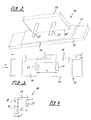
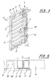
- Anhand eines illustrierten Ausführungsbeispiels wird die Erfindung näher erläutert. Es zeigen:
- Figur 1
- eine perspektivische Darstellung von zwei nebeneinander angeordneter ungleich grosser Rahmenschalelementen mit einer aufgesetzten Vorrichtung zum Ausschalen,
- Figur 2
- eine perspektivische Ansicht der Unterseite der Vorrichtung,
- Figur 3
- eine Vorderansicht der Vorrichtung,
- Figur 4
- eine Seitenansicht der Vorrichtung aus Richtung des Pfeiles P und
- Figur 5
- eine Aufsicht auf eine vergrösserte Darstellung des Bereichs A in
Figur 1 . - In der perspektivischen Darstellung gemäss
Figur 1 sind zwei Rahmenschalelemente 1 mit unterschiedlicher Breite, jedoch gleicher Höhe dargestellt. Die Rahmenschalelemente 1 umfassen je zwei parallel in einem Abstand liegende vertikal angeordnete Profilrohre 3, die an ihren Enden durch horizontal angeordnete Profilrohre 5 fest miteinander verbunden sind. Die Verbindung erfolgt an den Ecken durch Schweissungen oder durch andere Verbindungsmittel. Anstelle von rechteckförmigen Rohren können auch U-Profile verwendet werden. Im dargestellten Beispiel sind die beiden vertikalen verlaufenden Profilrohre 3 zwischen den horizontalen verlaufenden Profilrohren 5 durch acht horizontal verlaufende Zwischenstreben 7 miteinander fest verbunden. Als Zwischenstreben 7 können wiederum rechteckförmige Rohre oder U-förmige Profile mit nach unten oder von der Platte weggerichteten Schenkeln eingesetzt werden. Auf der Rückseite des Rahmenschalelements 1 ist eine den gesamten Querschnitt des Rahmenschalelements 1 umfassende Schalhaut in Gestalt einer Platte aus Holz, Kunststoff oder einem anderen Material befestigt. Zusätzlich können noch zwischen den vertikalen Profilrohren 3 die Zwischenraumstreben 7 untereinander verbindende, die Festigkeit des Rahmenschalelements 1 erhöhende Verstrebungen 11 eingeschweisst sein. An den Zwischenstreben 7 sind jeweils in der Nähe der vertikalen Profilrohre 3 meist paarweise angeordnete, die Zwischenstreben in vertikaler Richtung durchdringende Bohrungen oder Löcher 13 ausgebildet. Weitere Löcher 13 können auch an den Verstrebungen 11 vorgesehen sein, um auch dort das Aufsetzen einer Vorrichtung 15 zu ermöglichen. Rahmenschalelemente 1 der dargestellten und beschriebenen Art werden durch verschiedene Anbieter hergestellt. - Beim Aufbau einer Schalung für die Erstellung einer Wand aus Beton, werden die Rahmenschalelemente 1 dicht nebeneinander zusammengefügt und mittels die beiden vertikalen Profilrohre 3 zusammenpressenden Klammern oder Zwingen zusammengehalten (Klammern oder Zwingen nicht dargestellt; solche sind aus dem Stand der Technik hinlänglich bekannt).
- Damit die seitlich satt aneinander anliegenden Rahmenschalelemente 1 nach dem Giessen und mindestens teilweisem Aushärten des Betons von der erstellten Wand abgenommen werden können, muss mindestens eines der Rahmenschalelemente 1 translatorisch von der Wand weggezogen werden. Dabei ist die Reibung zwischen den jeweils aneinander anliegenden vertikalen Profilrohre 3 sowie die Haftung der Schalhaut 9 auf der Betonoberfläche zu überwinden.
Die erfindungsgemässe nachfolgend beschriebene Vorrichtung 15 ermöglicht diesen Vorgang auf einfache Weise. Die Vorrichtung 15 zum Ausschalen der Rahmenschalelemente 1 wird in denFiguren 2 bis 5 dargestellt und nachfolgend beschrieben. Sie umfasst im Wesentlichen zwei band- oder streifenförmige rechteckige Elemente aus Stahl 17, 19 und mindestens einen lotrecht auf der Unterseite des kürzeren Elementes 19 angeordneten Bolzen 21. Vorzugsweise sind zwei in einem Abstand a liegende Bolzen 21 vorgesehen. Die beiden rechteckförmigen Elemente 17, 19 weisen unterschiedliche Längen auf und sind entlang je einer ihrer Längskanten 17' und 19' miteinander verbunden, zum Beispiel verschweisst. Das oben liegende Element 19 ist kürzer als das unten liegende Element 17. Folglich überragt das längere Element 17 das kürzere Element 19 auf beiden Seiten um einen Betrag s, welcher in etwa der Breite b der jeweils nebeneinander liegenden vertikalen Profilrohre 3 entspricht (Fig. 3 ,5 ). Falls am kürzeren Element 19 zwei Bolzen 21 befestigt sind, so liegen diese in einem Abstand a, welcher exakt dem Abstand a von paarweise angeordneten Löcher 13 an den Zwischenstreben 7 entspricht. Der Abstand des mindestens einen Bolzens 21 von der Oberfläche des längeren Elements 17 beträgt e. Der Betrag e ist derart bemessen, dass, wenn die Vorrichtung 15 mit dem mindestens einen, vorzugsweise den zwei Bolzen 21 von oben auf eine Zwischenstrebe 7 aufgesteckt wird, die dem Bolzen 21 zugewendete Seite des längeren Elements 17 in einem Abstand zur freien Vorderkante der Zwischenstrebe 7 und der vertikalen Profilrohre 3 zu liegen kommt. Mit anderen Worten, zwischen den Profilrohren 3 und dem längeren Element 17 liegt ein Spalt S vor (Fig. 5 ). Dieser Spalt S dient dazu, um mit einem Geissfuss (nicht dargestellt) oder einem Hebeeisen eingreifen zu können und so das Rahmenschalelement 1, an welcher die Vorrichtung 15 eingehängt ist, translatorisch nach vorne, inFigur 5 nach unten, gezogen werden kann. Selbstverständlich muss der Geissfuss oder das Hebeeisen zwischen dem vertikalen Profilrohr 3 des benachbarten Rahmenschalelements und dem Element 17 eingeführt werden. Wird die Vorrichtung 15 an einer Verstrebung 11 angebracht, so erfolgt das Einführen eines Geissfusses zwischen die Vorrichtung 15 und dem benachbarten horizontalen Profilrohr 5.
Alternativ oder zusätzlich zum vergrösserten Abstand e der Bolzen 21 zu den Vorderkanten an den Zwischenstreben 7 kann auf dem längeren Element 17 eine Distanzplatte 18 aufgesetzt, zum Beispiel verschweisst oder mit dem längeren Element 17 auf andere Weise verbunden sein. Die Distanzplatte 18 ist kürzer als das lange Element 17, so dass seitlich der Distanzplatte 18 die Oberfläche des längeren Elements 17 freigestellt ist. Das Distanzelement weist eine Dicke t auf. In den durch die Distanzplatte 18 verursachten Spalt, wenn die Vorrichtung 15 an einem Rahmenschalelement 1 aufgesetzt ist, lässt sich dort der Geissfuss oder ein Hebeeisen einschieben. Damit ist sichergestellt, dass stets ein genügender Abstand S zum benachbarten Rahmenschalelement 1 vorhanden ist. - Der mindestens eine Bolzen 21 kann entweder auf das Element 19 aufgeschweisst oder in einer Bohrung im Element 19 geführt und dort befestigt sein. Selbstverständlich könnten die beiden Element 17 und 19 auch durch einen Stanz- und Biegeprozess aus einer einzigen Platte oder als Gussteil hergestellt sein und nicht wie oben beschrieben durch Schweissen miteinander verbunden sein.
- Vorzugsweise werden jeweils zwei Vorrichtungen gleichzeitig auf beiden Seiten am zuerst auszuschalenden Rahmenschalelement 1 aufgesetzt, so dass diese gleichzeitig an beiden Seitenkanten, d.h. die vertikalen Profilrohre 3, nach aussen gezogen werden können. Bei sehr grossen Rahmenschalelementen 1 kann es notwendig sein, dass die Vorrichtung 15 nicht auf halber Höhe angesetzt wird, sondern zuerst oben oder unten, um das Rahmenschalelement 1 im Bereich der vertikalen Profilrohre 3 zuerst von der erstellten Wand abzuheben.
-
- 1
- Rahmenschalelement.
- 3
- vertikales Profilrohr
- 5
- horizontales Profilrohr
- 7
- Zwischenstreben
- 9
- Schalhaut
- 11
- Verstrebung
- 13
- Löcher
- 15
- Vorrichtung
- 17
- Element lang
- 18
- Distanzplatte
- 19
- Element kurz
- 21
- Bolzen
Claims (8)
- Vorrichtung (15) zum Ausschalen von Rahmenschalelementen, (1) nach dem Erstellen von Wänden aus Beton, welche Rahmenschalelemente (1) einen rechteckigen Rahmen aus je zwei vertikalen Profilrohren (3) und zwei horizontalen Profilrohren (5) und mehrere mit Löchern (13) versehene Zwischenstreben (7), welche die beiden vertikalen Profilrohre (3) verbinden, umfassen, wobei die Vorrichtung (15)- ein erstes plattenförmiges Element (19) aus Stahl mit einer Breite b und einer Länge l aufweist, an welchem mindestens ein lotrecht zur Plattenoberfläche stehender Bolzen (21) befestigt ist und weiter- ein zweites Element (17), das in rechtem Winkel zum ersten Element (19) entlang einer Längskante mit diesem verbunden ist, umfasst, wobei das zweite Element (17) eine grössere Länge L aufweist als die Länge l des ersten Elements (19) aufweist, so dass das zweite Element (17) mindestens eine der Seitenkanten des ersten Elements (19) seitlich überragt.
- Vorrichtung nach Anspruch 1, dadurch gekennzeichnet, dass zwischen dem ersten (19) und dem zweiten Element (17) eine Distanzplatte (18) angeordnet ist, deren Länge kleiner ist als die Länge L des zweiten Elements (17).
- Vorrichtung nach Anspruch 1 oder 2, dadurch gekennzeichnet, dass am ersten Element (19) zwei Bolzen (21) in einem Abstand a nebeneinander und je in einem Abstand e zur Oberfläche des zweiten Elements (17) angeordnet sind.
- Vorrichtung nach einem der Ansprüche 2 oder 3, dadurch gekennzeichnet, dass der gegenseitige Abstand a der Bolzen (21) dem Abstand von an den Zwischenstreben (7) des Rahmenschalelements (1) ausgebildeten Löchern (13) entspricht.
- Vorrichtung nach einem der Ansprüche 3 oder 4, dadurch gekennzeichnet, dass der Abstand e des mindestens einen Bolzens (21) vom zweiten Element (17) und/oder von der Distanzplatte (18) grösser ist als der Abstand der Löcher (13) an den Zwischenstreben (7) von der aussenliegenden freien Kante der Zwischenstreben (7).
- Vorrichtung nach einem der Ansprüche 1 bis 5, dadurch gekennzeichnet, dass das zweite Element (17) die Seitenkanten des ersten Elements (19) beidseitig überragt.
- Vorrichtung nach einem der Ansprüche 1 bis 6, dadurch gekennzeichnet, dass das erste und das zweite Element (19,17) miteinander verschweisst oder verschraubt und in einem rechten Winkel zueinander angeordnet sind.
- Vorrichtung nach einem der Ansprüche 1 bis 6, dadurch gekennzeichnet, dass die beiden Elemente (17, 19) aus Guss hergestellt sind und eine Einheit bilden.
Applications Claiming Priority (1)
| Application Number | Priority Date | Filing Date | Title |
|---|---|---|---|
| CH00808/14A CH709699A1 (de) | 2014-05-27 | 2014-05-27 | Vorrichtung zum Ausschalen von Rahmenschalelementen. |
Publications (3)
| Publication Number | Publication Date |
|---|---|
| EP2949835A1 true EP2949835A1 (de) | 2015-12-02 |
| EP2949835C0 EP2949835C0 (de) | 2024-02-28 |
| EP2949835B1 EP2949835B1 (de) | 2024-02-28 |
Family
ID=53540702
Family Applications (1)
| Application Number | Title | Priority Date | Filing Date |
|---|---|---|---|
| EP15405034.8A Active EP2949835B1 (de) | 2014-05-27 | 2015-05-01 | Vorrichtung zum ausschalen von rahmenschalelementen |
Country Status (2)
| Country | Link |
|---|---|
| EP (1) | EP2949835B1 (de) |
| CH (1) | CH709699A1 (de) |
Citations (3)
| Publication number | Priority date | Publication date | Assignee | Title |
|---|---|---|---|---|
| JPS5273924U (de) * | 1975-12-01 | 1977-06-02 | ||
| JPS63111547U (de) * | 1987-01-09 | 1988-07-18 | ||
| JPS63165043U (de) * | 1987-04-17 | 1988-10-27 |
Family Cites Families (5)
| Publication number | Priority date | Publication date | Assignee | Title |
|---|---|---|---|---|
| GB910699A (en) * | 1960-08-16 | 1962-11-14 | Alexander Feldmann | Improvements in means for and methods of separating shuttering from cast concrete |
| DE3213482C1 (de) * | 1982-04-10 | 1983-06-01 | Maier, Josef, 7611 Steinach | Ausschalhilfe |
| US20050120672A1 (en) * | 2001-12-07 | 2005-06-09 | Form Puller Tool Co., Inc. | Method and apparatus for removing modular forms |
| AU2003304537A1 (en) * | 2003-10-16 | 2004-06-06 | Form Puller Tool Co., Inc. | Device for removing modular forms |
| US7204480B1 (en) * | 2006-06-20 | 2007-04-17 | Mark Simmons | Prying tool for dislodging concrete forms from poured concrete walls |
-
2014
- 2014-05-27 CH CH00808/14A patent/CH709699A1/de unknown
-
2015
- 2015-05-01 EP EP15405034.8A patent/EP2949835B1/de active Active
Patent Citations (3)
| Publication number | Priority date | Publication date | Assignee | Title |
|---|---|---|---|---|
| JPS5273924U (de) * | 1975-12-01 | 1977-06-02 | ||
| JPS63111547U (de) * | 1987-01-09 | 1988-07-18 | ||
| JPS63165043U (de) * | 1987-04-17 | 1988-10-27 |
Also Published As
| Publication number | Publication date |
|---|---|
| CH709699A1 (de) | 2015-11-30 |
| EP2949835C0 (de) | 2024-02-28 |
| EP2949835B1 (de) | 2024-02-28 |
Similar Documents
| Publication | Publication Date | Title |
|---|---|---|
| EP3384108B1 (de) | Schalungsteil und deckenschalung mit einem solchen schalungsteil | |
| EP0410079A1 (de) | Anschlussschalung für aneinander anschliessende Betonplatten | |
| DE102010035330A1 (de) | Vorrichtung zur Befestigung eines Bohrständers für eine Bohrmaschine | |
| EP0002814B2 (de) | Betonschalung aus Schaltafeln mit Keilverbindung | |
| DE202011004223U1 (de) | Bewehrungsrahmen für eine Betonplatte | |
| EP2949835B1 (de) | Vorrichtung zum ausschalen von rahmenschalelementen | |
| DE202011100030U1 (de) | Vorrichtung zur Verbindung und Befestigung von Gittermatten | |
| DE202020102278U1 (de) | Eckkonsole | |
| DE19950226A1 (de) | Schalung zur Errichtung einer Säule oder einer Stütze eines Bauwerks | |
| DE202006009860U1 (de) | Aussteifungsstruktur und Befestigungselement zur Aussteifung einer Stützen aufweisenden Unterstellung einer Deckenschalung | |
| EP2921610B9 (de) | Vorrichtung zum befestigen von verkleidungen an gerüsten | |
| EP2980333B1 (de) | Baugerüst mit einem gerüstelement | |
| EP2524781B1 (de) | Pressvorrichtung mit einer Lochplatte | |
| AT521074A2 (de) | Abschalwinkel und ein Erweiterungselement für einen Abschalwinkel | |
| DE1684303C3 (de) | Schalung für Beton- oder Stahlbetonwände | |
| DE4336157C2 (de) | Schalungssystem für ein Mantelbeton-Mauerwerk | |
| DE1534897C (de) | Vorrichtung zum Ausschalen von Stahlbetonrippen oder Kassettendecken od dgl | |
| DE4332526A1 (de) | Vorrichtung zum Einschalen von Bauwerksöffnungen, -Türen -Fenster | |
| DE3546590C2 (de) | ||
| DE2504162C3 (de) | In Betonkonstruktionen bündig einbettbarer Schwerlastanker | |
| DE202015102013U1 (de) | Transporthilfe | |
| DE29923274U1 (de) | Klemmvorrichtung zum Aneinanderklemmen von zwei sich im wesentlichen rechtwinklig kreuzenden Balken | |
| DE19939844A1 (de) | Verbindungselement für Schalungsplatten | |
| DE1684349A1 (de) | Eckenanschlussvorrichtung fuer Bauverschalungen | |
| DE10302284A1 (de) | Verbrauvorrichtung und Verbauplatte sowie Kammerplatte hierfür |
Legal Events
| Date | Code | Title | Description |
|---|---|---|---|
| AK | Designated contracting states |
Kind code of ref document: A1 Designated state(s): AL AT BE BG CH CY CZ DE DK EE ES FI FR GB GR HR HU IE IS IT LI LT LU LV MC MK MT NL NO PL PT RO RS SE SI SK SM TR |
|
| AX | Request for extension of the european patent |
Extension state: BA ME |
|
| PUAI | Public reference made under article 153(3) epc to a published international application that has entered the european phase |
Free format text: ORIGINAL CODE: 0009012 |
|
| 17P | Request for examination filed |
Effective date: 20160427 |
|
| RBV | Designated contracting states (corrected) |
Designated state(s): AL AT BE BG CH CY CZ DE DK EE ES FI FR GB GR HR HU IE IS IT LI LT LU LV MC MK MT NL NO PL PT RO RS SE SI SK SM TR |
|
| STAA | Information on the status of an ep patent application or granted ep patent |
Free format text: STATUS: EXAMINATION IS IN PROGRESS |
|
| 17Q | First examination report despatched |
Effective date: 20190903 |
|
| GRAP | Despatch of communication of intention to grant a patent |
Free format text: ORIGINAL CODE: EPIDOSNIGR1 |
|
| STAA | Information on the status of an ep patent application or granted ep patent |
Free format text: STATUS: GRANT OF PATENT IS INTENDED |
|
| INTG | Intention to grant announced |
Effective date: 20230210 |
|
| RIC1 | Information provided on ipc code assigned before grant |
Ipc: E04G 9/02 20060101ALN20230130BHEP Ipc: E04G 19/00 20060101AFI20230130BHEP |
|
| GRAJ | Information related to disapproval of communication of intention to grant by the applicant or resumption of examination proceedings by the epo deleted |
Free format text: ORIGINAL CODE: EPIDOSDIGR1 |
|
| STAA | Information on the status of an ep patent application or granted ep patent |
Free format text: STATUS: EXAMINATION IS IN PROGRESS |
|
| INTC | Intention to grant announced (deleted) | ||
| RIC1 | Information provided on ipc code assigned before grant |
Ipc: E04G 9/02 20060101ALN20230710BHEP Ipc: E04G 19/00 20060101AFI20230710BHEP |
|
| GRAP | Despatch of communication of intention to grant a patent |
Free format text: ORIGINAL CODE: EPIDOSNIGR1 |
|
| STAA | Information on the status of an ep patent application or granted ep patent |
Free format text: STATUS: GRANT OF PATENT IS INTENDED |
|
| INTG | Intention to grant announced |
Effective date: 20230921 |
|
| RIC1 | Information provided on ipc code assigned before grant |
Ipc: E04G 9/02 20060101ALN20230911BHEP Ipc: E04G 19/00 20060101AFI20230911BHEP |
|
| GRAS | Grant fee paid |
Free format text: ORIGINAL CODE: EPIDOSNIGR3 |
|
| GRAA | (expected) grant |
Free format text: ORIGINAL CODE: 0009210 |
|
| STAA | Information on the status of an ep patent application or granted ep patent |
Free format text: STATUS: THE PATENT HAS BEEN GRANTED |
|
| AK | Designated contracting states |
Kind code of ref document: B1 Designated state(s): AL AT BE BG CH CY CZ DE DK EE ES FI FR GB GR HR HU IE IS IT LI LT LU LV MC MK MT NL NO PL PT RO RS SE SI SK SM TR |
|
| REG | Reference to a national code |
Ref country code: GB Ref legal event code: FG4D Free format text: NOT ENGLISH |
|
| REG | Reference to a national code |
Ref country code: CH Ref legal event code: EP |
|
| REG | Reference to a national code |
Ref country code: DE Ref legal event code: R096 Ref document number: 502015016759 Country of ref document: DE |
|
| REG | Reference to a national code |
Ref country code: IE Ref legal event code: FG4D Free format text: LANGUAGE OF EP DOCUMENT: GERMAN |
|
| U01 | Request for unitary effect filed |
Effective date: 20240328 |
|
| U07 | Unitary effect registered |
Designated state(s): AT BE BG DE DK EE FI FR IT LT LU LV MT NL PT SE SI Effective date: 20240409 |
|
| U20 | Renewal fee for the european patent with unitary effect paid |
Year of fee payment: 10 Effective date: 20240516 |
|
| PG25 | Lapsed in a contracting state [announced via postgrant information from national office to epo] |
Ref country code: IS Free format text: LAPSE BECAUSE OF FAILURE TO SUBMIT A TRANSLATION OF THE DESCRIPTION OR TO PAY THE FEE WITHIN THE PRESCRIBED TIME-LIMIT Effective date: 20240628 |
|
| PG25 | Lapsed in a contracting state [announced via postgrant information from national office to epo] |
Ref country code: GR Free format text: LAPSE BECAUSE OF FAILURE TO SUBMIT A TRANSLATION OF THE DESCRIPTION OR TO PAY THE FEE WITHIN THE PRESCRIBED TIME-LIMIT Effective date: 20240529 |
|
| PG25 | Lapsed in a contracting state [announced via postgrant information from national office to epo] |
Ref country code: HR Free format text: LAPSE BECAUSE OF FAILURE TO SUBMIT A TRANSLATION OF THE DESCRIPTION OR TO PAY THE FEE WITHIN THE PRESCRIBED TIME-LIMIT Effective date: 20240228 Ref country code: RS Free format text: LAPSE BECAUSE OF FAILURE TO SUBMIT A TRANSLATION OF THE DESCRIPTION OR TO PAY THE FEE WITHIN THE PRESCRIBED TIME-LIMIT Effective date: 20240528 |
|
| PG25 | Lapsed in a contracting state [announced via postgrant information from national office to epo] |
Ref country code: ES Free format text: LAPSE BECAUSE OF FAILURE TO SUBMIT A TRANSLATION OF THE DESCRIPTION OR TO PAY THE FEE WITHIN THE PRESCRIBED TIME-LIMIT Effective date: 20240228 |
|
| PG25 | Lapsed in a contracting state [announced via postgrant information from national office to epo] |
Ref country code: RS Free format text: LAPSE BECAUSE OF FAILURE TO SUBMIT A TRANSLATION OF THE DESCRIPTION OR TO PAY THE FEE WITHIN THE PRESCRIBED TIME-LIMIT Effective date: 20240528 Ref country code: NO Free format text: LAPSE BECAUSE OF FAILURE TO SUBMIT A TRANSLATION OF THE DESCRIPTION OR TO PAY THE FEE WITHIN THE PRESCRIBED TIME-LIMIT Effective date: 20240528 Ref country code: IS Free format text: LAPSE BECAUSE OF FAILURE TO SUBMIT A TRANSLATION OF THE DESCRIPTION OR TO PAY THE FEE WITHIN THE PRESCRIBED TIME-LIMIT Effective date: 20240628 Ref country code: HR Free format text: LAPSE BECAUSE OF FAILURE TO SUBMIT A TRANSLATION OF THE DESCRIPTION OR TO PAY THE FEE WITHIN THE PRESCRIBED TIME-LIMIT Effective date: 20240228 Ref country code: GR Free format text: LAPSE BECAUSE OF FAILURE TO SUBMIT A TRANSLATION OF THE DESCRIPTION OR TO PAY THE FEE WITHIN THE PRESCRIBED TIME-LIMIT Effective date: 20240529 Ref country code: ES Free format text: LAPSE BECAUSE OF FAILURE TO SUBMIT A TRANSLATION OF THE DESCRIPTION OR TO PAY THE FEE WITHIN THE PRESCRIBED TIME-LIMIT Effective date: 20240228 |
|
| PG25 | Lapsed in a contracting state [announced via postgrant information from national office to epo] |
Ref country code: PL Free format text: LAPSE BECAUSE OF FAILURE TO SUBMIT A TRANSLATION OF THE DESCRIPTION OR TO PAY THE FEE WITHIN THE PRESCRIBED TIME-LIMIT Effective date: 20240228 |
|
| PG25 | Lapsed in a contracting state [announced via postgrant information from national office to epo] |
Ref country code: PL Free format text: LAPSE BECAUSE OF FAILURE TO SUBMIT A TRANSLATION OF THE DESCRIPTION OR TO PAY THE FEE WITHIN THE PRESCRIBED TIME-LIMIT Effective date: 20240228 |
|
| PG25 | Lapsed in a contracting state [announced via postgrant information from national office to epo] |
Ref country code: SM Free format text: LAPSE BECAUSE OF FAILURE TO SUBMIT A TRANSLATION OF THE DESCRIPTION OR TO PAY THE FEE WITHIN THE PRESCRIBED TIME-LIMIT Effective date: 20240228 |
|
| PG25 | Lapsed in a contracting state [announced via postgrant information from national office to epo] |
Ref country code: CZ Free format text: LAPSE BECAUSE OF FAILURE TO SUBMIT A TRANSLATION OF THE DESCRIPTION OR TO PAY THE FEE WITHIN THE PRESCRIBED TIME-LIMIT Effective date: 20240228 |
|
| PG25 | Lapsed in a contracting state [announced via postgrant information from national office to epo] |
Ref country code: SK Free format text: LAPSE BECAUSE OF FAILURE TO SUBMIT A TRANSLATION OF THE DESCRIPTION OR TO PAY THE FEE WITHIN THE PRESCRIBED TIME-LIMIT Effective date: 20240228 |
|
| PG25 | Lapsed in a contracting state [announced via postgrant information from national office to epo] |
Ref country code: SM Free format text: LAPSE BECAUSE OF FAILURE TO SUBMIT A TRANSLATION OF THE DESCRIPTION OR TO PAY THE FEE WITHIN THE PRESCRIBED TIME-LIMIT Effective date: 20240228 Ref country code: SK Free format text: LAPSE BECAUSE OF FAILURE TO SUBMIT A TRANSLATION OF THE DESCRIPTION OR TO PAY THE FEE WITHIN THE PRESCRIBED TIME-LIMIT Effective date: 20240228 Ref country code: RO Free format text: LAPSE BECAUSE OF FAILURE TO SUBMIT A TRANSLATION OF THE DESCRIPTION OR TO PAY THE FEE WITHIN THE PRESCRIBED TIME-LIMIT Effective date: 20240228 Ref country code: CZ Free format text: LAPSE BECAUSE OF FAILURE TO SUBMIT A TRANSLATION OF THE DESCRIPTION OR TO PAY THE FEE WITHIN THE PRESCRIBED TIME-LIMIT Effective date: 20240228 |
|
| REG | Reference to a national code |
Ref country code: DE Ref legal event code: R097 Ref document number: 502015016759 Country of ref document: DE |
|
| PLBE | No opposition filed within time limit |
Free format text: ORIGINAL CODE: 0009261 |
|
| STAA | Information on the status of an ep patent application or granted ep patent |
Free format text: STATUS: NO OPPOSITION FILED WITHIN TIME LIMIT |
|
| PG25 | Lapsed in a contracting state [announced via postgrant information from national office to epo] |
Ref country code: MC Free format text: LAPSE BECAUSE OF FAILURE TO SUBMIT A TRANSLATION OF THE DESCRIPTION OR TO PAY THE FEE WITHIN THE PRESCRIBED TIME-LIMIT Effective date: 20240228 |
|
| PG25 | Lapsed in a contracting state [announced via postgrant information from national office to epo] |
Ref country code: MC Free format text: LAPSE BECAUSE OF FAILURE TO SUBMIT A TRANSLATION OF THE DESCRIPTION OR TO PAY THE FEE WITHIN THE PRESCRIBED TIME-LIMIT Effective date: 20240228 |
|
| 26N | No opposition filed |
Effective date: 20241129 |
|
| PG25 | Lapsed in a contracting state [announced via postgrant information from national office to epo] |
Ref country code: IE Free format text: LAPSE BECAUSE OF NON-PAYMENT OF DUE FEES Effective date: 20240501 |
|
| U20 | Renewal fee for the european patent with unitary effect paid |
Year of fee payment: 11 Effective date: 20250520 |
|
| PGFP | Annual fee paid to national office [announced via postgrant information from national office to epo] |
Ref country code: GB Payment date: 20250527 Year of fee payment: 11 |
|
| PGFP | Annual fee paid to national office [announced via postgrant information from national office to epo] |
Ref country code: CH Payment date: 20250601 Year of fee payment: 11 |
|
| PG25 | Lapsed in a contracting state [announced via postgrant information from national office to epo] |
Ref country code: CY Free format text: LAPSE BECAUSE OF FAILURE TO SUBMIT A TRANSLATION OF THE DESCRIPTION OR TO PAY THE FEE WITHIN THE PRESCRIBED TIME-LIMIT; INVALID AB INITIO Effective date: 20150501 |
|
| PG25 | Lapsed in a contracting state [announced via postgrant information from national office to epo] |
Ref country code: HU Free format text: LAPSE BECAUSE OF FAILURE TO SUBMIT A TRANSLATION OF THE DESCRIPTION OR TO PAY THE FEE WITHIN THE PRESCRIBED TIME-LIMIT; INVALID AB INITIO Effective date: 20150501 |