EP2949846A1 - Vorrichtung zum bewegen einer möbelklappe und möbel - Google Patents
Vorrichtung zum bewegen einer möbelklappe und möbel Download PDFInfo
- Publication number
- EP2949846A1 EP2949846A1 EP15167464.5A EP15167464A EP2949846A1 EP 2949846 A1 EP2949846 A1 EP 2949846A1 EP 15167464 A EP15167464 A EP 15167464A EP 2949846 A1 EP2949846 A1 EP 2949846A1
- Authority
- EP
- European Patent Office
- Prior art keywords
- actuating arm
- furniture
- bearing
- flap
- arm
- Prior art date
- Legal status (The legal status is an assumption and is not a legal conclusion. Google has not performed a legal analysis and makes no representation as to the accuracy of the status listed.)
- Granted
Links
Images



Classifications
-
- E—FIXED CONSTRUCTIONS
- E05—LOCKS; KEYS; WINDOW OR DOOR FITTINGS; SAFES
- E05D—HINGES OR SUSPENSION DEVICES FOR DOORS, WINDOWS OR WINGS
- E05D15/00—Suspension arrangements for wings
- E05D15/26—Suspension arrangements for wings for folding wings
- E05D15/262—Suspension arrangements for wings for folding wings folding vertically
-
- E—FIXED CONSTRUCTIONS
- E05—LOCKS; KEYS; WINDOW OR DOOR FITTINGS; SAFES
- E05Y—INDEXING SCHEME ASSOCIATED WITH SUBCLASSES E05D AND E05F, RELATING TO CONSTRUCTION ELEMENTS, ELECTRIC CONTROL, POWER SUPPLY, POWER SIGNAL OR TRANSMISSION, USER INTERFACES, MOUNTING OR COUPLING, DETAILS, ACCESSORIES, AUXILIARY OPERATIONS NOT OTHERWISE PROVIDED FOR, APPLICATION THEREOF
- E05Y2600/00—Mounting or coupling arrangements for elements provided for in this subclass
- E05Y2600/50—Mounting methods; Positioning
- E05Y2600/52—Toolless
- E05Y2600/528—Hooking, e.g. using bayonets; Locking
-
- E—FIXED CONSTRUCTIONS
- E05—LOCKS; KEYS; WINDOW OR DOOR FITTINGS; SAFES
- E05Y—INDEXING SCHEME ASSOCIATED WITH SUBCLASSES E05D AND E05F, RELATING TO CONSTRUCTION ELEMENTS, ELECTRIC CONTROL, POWER SUPPLY, POWER SIGNAL OR TRANSMISSION, USER INTERFACES, MOUNTING OR COUPLING, DETAILS, ACCESSORIES, AUXILIARY OPERATIONS NOT OTHERWISE PROVIDED FOR, APPLICATION THEREOF
- E05Y2600/00—Mounting or coupling arrangements for elements provided for in this subclass
- E05Y2600/50—Mounting methods; Positioning
- E05Y2600/56—Positioning, e.g. re-positioning, or pre-mounting
-
- E—FIXED CONSTRUCTIONS
- E05—LOCKS; KEYS; WINDOW OR DOOR FITTINGS; SAFES
- E05Y—INDEXING SCHEME ASSOCIATED WITH SUBCLASSES E05D AND E05F, RELATING TO CONSTRUCTION ELEMENTS, ELECTRIC CONTROL, POWER SUPPLY, POWER SIGNAL OR TRANSMISSION, USER INTERFACES, MOUNTING OR COUPLING, DETAILS, ACCESSORIES, AUXILIARY OPERATIONS NOT OTHERWISE PROVIDED FOR, APPLICATION THEREOF
- E05Y2900/00—Application of doors, windows, wings or fittings thereof
- E05Y2900/20—Application of doors, windows, wings or fittings thereof for furniture, e.g. cabinets
Definitions
- Devices for moving a furniture flap movably received on a furniture body are known. Such devices act between the furniture body and the furniture flap and are designed as hinges or flap fittings to allow a swinging out of the furniture flap from a closed position on the furniture body in the direction of an open position of the furniture flap and back to the closed position.
- the device For furniture flaps with two hingedly connected cooperating flap segments, the device must be more complex with respect to a device for a single flap.
- Modern flap fittings regularly have additional facilities such as a damper assembly and a power unit, which affect the furniture flap movement.
- the invention has for its object, advantageously advantageous to further improve said devices, in particular with regard to the prevention of malfunction and the installation of the device to the furniture.
- This object is solved by the independent claims.
- the dependent claims thematize advantageous developments of the invention.
- the invention relates to a device for moving a on a furniture body movably received furniture flap with an upper flap element and a lower flap element, which are coupled together, wherein the device comprises a pivotable support arm which is connectable to the upper flap element, and an actuating arm of the furniture body side taken over a first bearing point of the actuating arm and with the lower flap element via a second bearing point of the actuating arm is connectable.
- the bearings are provided by the device itself.
- the device according to the invention is in particular a furniture flap fitting such as a folding flap fitting for two hingedly cooperating folding flap elements of a furniture flap of a piece of furniture.
- the flap fitting can be designed, in particular, as a 7-joint or as a 4-joint with a plurality of articulated arms which interact with one another in an articulated manner.
- attachment means are provided for releasably connecting the actuator arm to a bearing point of the actuator arm, wherein the attachment means comprises an actuator arm connection part on the actuator arm and a connection part on a connectable to the actuator arm connection portion of the bearing point, and wherein the attachment means are formed such that the Connection can be established by a combination of a plug movement and a rotational movement of the actuator arm connection part.
- the combination of the plugging movement and the rotational movement of the actuating arm connecting part is advantageous in that initially only one movement and then only the other type of movement takes place, so for example initially only the plug movement without rotational movement and then after Termination of the plug-in motion alone, the rotational movement takes place without a movement in the direction of the plug-in movement or vice versa.
- This allows for a particularly simple attachment, since the translational or linear plug movement and the rotary rotational movement do not take place superimposed, but this is not excluded.
- first a first plugging movement then comprise a first rotational movement and then a second plugging movement and / or a second rotational movement of the Stellarm-connecting part, optionally, the second Rotational movement in the opposite direction of rotation for the first rotational movement.
- the arrangement according to the invention is particularly advantageous for a procedure during assembly, according to which the actuating arm to be attached to the bearing in question is freely movable or not connected to the flap element or furniture body side via any other bearing point, as is the case in the fully assembled state.
- the plug-in and rotary movement can take place without problems, in particular since a corresponding assembly movement of the actuating arm is not limited in space.
- the relevant bearing point on which the attachment is made by a combined plugging and turning may be the first or second bearing point of the actuator arm. After attaching the actuating arm to the relevant bearing point of the entire arm still spatially so adjusted, for example, in particular be pivoted about the provided with the bearing pivot axis of the actuating arm, that the actuating arm can be attached to the other bearing point.
- the attachment to the other bearing usually takes place in a different way or not with a combined plug and rotary movement of another actuator arm connecting part, for example by clipping, snapping or screwing.
- the two bearing points of the actuator arm are respectively in particular at least rotary or pivot bearings.
- the rotary and plug movement of the actuating arm connecting part relates to a mounting of the device or the actuating arm on the furniture, which z. B. is necessary at the first attachment of the device to the furniture. Since the actuator arm is a rigidly behaving in operation mechanical component, the actuator arm connection part is fixed to the actuator arm available. Accordingly, the plug-in and rotary movement of the actuator arm connecting part is realized with a corresponding movement of the entire actuator arm.
- the cooperating with the actuator arm connecting part for mounting the actuating arm connecting part at the bearing point is provided separately from the actuating arm on the device or on the furniture body or on the flap element.
- the actuating arm connecting part and the associated connecting part are designed coordinated so that only in the thus predetermined combination or sequence of plug and rotary movement of the actuating arm connecting part attachment of the actuating arm on or decrease of the bearing can take place. This is z. B. accidental attachment of the actuator arm in a non-functional orientation or incorrect assembly excluded.
- the device according to the invention optionally has a power unit, which in the assembled state of the device, an opening and / or closing movement of the furniture flap by a force provided by the power unit force at least supported.
- the power unit acts in particular on the support and / or actuator arm.
- the attachment means are designed as bayonet closure means.
- the bayonet closure means comprise all variants or concrete implementations which allow a connection in the manner of a bayonet closure.
- the attachment means are space-saving, stable and functionally advantageous for attaching and detaching the connection.
- the attachment means for releasably connecting the actuator arm to the furniture body side bearing point of the actuator arm are present.
- the connectable with the actuator arm connection part connecting part of the bearing can be advantageously prepared prepared on a fitting part of the device.
- the fitting part comprises the other parts of the device and is attached to the furniture body in particular on an inner side of a side wall of the furniture body. With the correct positioning of the fitting on the furniture body is thus advantageously also the connecting part of the bearing, which is not formed on the actuating arm provided.
- the attachment means are tuned such that a device of the connection of the actuating arm to the bearing is possible only in a spatial orientation of the actuating arm, which does not occupy the actuating arm in the assembled state of the device during a movement of the furniture flap. This ensures that the connection of the actuating arm at the bearing point, which takes place via the actuating arm connecting part and the connecting part, during operation of the device is not solvable. Because the actuator arm is in all possible operating conditions in the functional opening and closing of the furniture flap in a spatial orientation, which differs from the spatial orientation, which is assumed to be the Disconnect connection of the actuator arm at the bearing point again. The spatial orientation of the actuating arm, which is absolutely necessary in the establishment of the connection to the bearing, the spatial orientation, which is necessary to cancel the connection of the actuator arm at the bearing point.
- An advantageous modification of the subject invention is characterized in that the attachment means are designed such that a necessary for a connection of the actuator arm to the bearing plug movement of Stellarm connecting part relative to the connecting part of the bearing only in a spatial orientation of the actuator arm is possible, which is Based on the mounted state of the device differs from all the different orientations of the actuator arm, which occupies the actuator arm during movement of the furniture flap when opening or closing the furniture flap.
- This is with respect to a combination of the plug and the rotary movement of the actuating arm connecting part, in which, for example, first a plug movement takes place before the rotational movement takes place or can take place, advantageous.
- the connection process is z. B.
- the plug-in motion is a prerequisite for this or represents the initiating process, which must be mandatory before the subsequent phase of the connection process can begin with the rotational movement.
- a rotation of the actuating arm connection part is only possible if the plug movement has previously been completed.
- the rotation of the actuator arm connection part mentioned in this context means twisting, which contributes to the connection of the actuator arm that can be realized with the attachment means. This means that the twisting a funk-right interaction of actuator arm connection part and the associated connecting part at the bearing requires and z. B. does not affect any kind of twisting the actuator arm connection part, which does not take place in properly functioning interaction with the bearing.
- the positioning arm separates from the relevant, in particular furniture body-side, bearing point.
- the prerequisite is that the actuating arm knows at least one spatial orientation in which the actuating arm connecting part can be brought relative to the associated connecting part at the bearing point, which differs from all spatial orientations of the actuating arm when moving the furniture flap during operation of the device.
- These also as z. B. mounting orientation designated alignment is particularly possible only if the actuator arm to be mounted is not added to the other bearing.
- Attachment to the other bearing which is done in particular by not inventive or known attachment means, for variants according to the invention basically only take place when the bearing point of the actuator arm is completely set up with the attachment means according to the invention.
- the attachment means comprises a journal section with a projection protruding radially outward from a bearing axis of the bearing point on the section of the bearing point which can be connected to the actuator arm connection part. This is compact and easy to implement.
- the attachment means on the actuating arm connecting part on an opening which has a radially outwardly projecting recess to the bearing axis.
- a pin portion with a bearing axis to a bearing axis of the bearing radially outwardly projecting projection on the connectable to the actuator arm connection portion of the bearing point is present, and on Stellarm-connecting part adapted to the pin portion opening exists, which has a radially outwardly projecting recess to the bearing axis, wherein the opening is adapted for attachment to the pin portion, so that the projection fits through the recess.
- the projection is present in particular only over part of the length of the pin section.
- the journal section has, in addition to the section with the projection, a section, in particular in a slender or oblong shape, which is set back relative to the projection radially to the longitudinal axis of the journal section.
- the section in oblong shape is z. B. cylindrical or otherwise regularly z. B. polygonal shaped.
- a section without a projection adjoins the region with the projection. The correct orientation of the actuating arm when attaching the actuating arm or the actuating arm connecting part on the journal portion results from the position in which the recess is fitting pushed over the projection.
- the actuator arm connection part and connectable to the actuator arm connection portion of the bearing point after the key-lock principle can be formed.
- the opening with the recess on the actuating arm connecting part is advantageously formed in shape and size complementary to the journal portion with the projection.
- the outline of the opening coincides with the recess and the outline of the pin portion with the projection at least substantially or is possibly such that during the insertion movement of the actuator arm or the Stellarm-connecting part is a slight clearance or small air gap between the Outlines of the opening with the recess on the one hand and the pin portion with the projection on the other hand results.
- the dimension of the recess or corresponding to the dimension of the projection in circumferential direction to the bearing axis or in the insertion direction is formed to the entire circumferential dimension only over a partial circumference or in particular comparatively narrow, designed for example over about 40 to 80 degrees.
- the opening on the actuating arm connecting part for attaching the Stellarm-connecting part on the journal portion aligned on the actuating arm connecting part is present, that the actuating arm can be attached only in a predetermined orientation on the furniture body side bearing, wherein the predetermined Alignment is not Solutionsstbare in the operation of the device for moving the furniture flaps of the actuator arm orientation.
- a furniture body side mountable base member which includes the connectable to the actuator arm connection portion of the furniture body side bearing point of the actuator arm.
- the basic component the essential or all furniture body-side parts of the device or the flap fitting can be provided on a component by the manufacturer. After the assembly of the basic component to the furniture body, the connection with the furniture flap or the flap elements via articulated elements of the device, in particular hinge arms is to make.
- the device according to the invention is advantageously designed such that an arrangement with a damper arrangement for damping the movement of the movable furniture part is provided, wherein the damper assembly comprises a damper, wherein for a damping effect of the damper arrangement a temporary contact of the damper takes place with a movable counter portion of the device , and wherein in the assembled state of the device, a movement of the counter portion is carried out depending on a movement of the furniture part.
- the movement of the movable furniture part or the furniture flap can be advantageously damped in an opening and / or closing movement of the furniture flap element.
- the damping of the movement can be set up, in particular, before reaching a completely closed or fully open position of the furniture flap relative to the furniture body. As a result, impact noises or damage to the furniture and the device can be avoided.
- the damper is designed in particular as a fluid damper such as an air or oil damper.
- the invention also relates to a piece of furniture having a furniture flap accommodated on a furniture body with an upper flap element and a lower flap element which are coupled to one another, wherein the furniture flap is movable in an opening direction and in a closing direction relative to the furniture body, wherein a device according to the above training is provided.
- a piece of furniture with a furniture flap can be provided, in which the explained advantages can be achieved.
- FIG. 1 shows a part of a piece of furniture 1 with a furniture body 2, of which only one side wall 3 of two identical vertical side walls is shown.
- the furniture body 2 comprises between the side walls a horizontal lower bottom part 4 and an upper lid part 5.
- an optionally present rear wall of the furniture body 2 is also not shown.
- an inventive device for moving a folding furniture flap 6 is mounted below the lid part 5, which is designed as a furniture fitting or as a flap fitting 7 for pivoting the folding furniture flap 6 relative to the furniture body 2.
- a front opening 2a of the furniture body 2 can be covered or released, so that when the folding furniture flap 6 is open according to FIG. 1 an internal volume of the furniture body 2 is accessible from the front in the direction P1.
- the folding furniture flap 6 is constructed of two flap elements with an upper folding flap 8 and a lower folding flap 9. Between the lower region of the folding flap 8 and the upper region of the folding flap 9, a joint arrangement 10 is provided on the inside, via which the folding flaps 8 and 9 are connected to one another in an articulated manner.
- the flap fitting 7 which is designed here as a multi-joint, for example as a 7-joint, has a fitting part 7a mounted on the inside of the side wall 3 and a holding part 7b mounted on an upper folding flap 8 with hinge elements acting therebetween.
- the hinge elements comprise articulated support arms 17 and 18 and intermediate arms 19 and 20, which serve for pivotal movement of the upper folding flap 8.
- flap fitting 7 could basically also a flap fitting, which is constructed as a 4-joint, may be provided.
- the flap fitting 7 for movable guidance of the lower folding flap 9 comprises a positioning arm 21 designed control lever for the lower folding flap 9, the articulated on the one hand via a bearing 28 furniture body side and on the other hand via a further bearing point or a support joint 22 and a hinge fitting is added to the inside of the lower folding flap 9.
- the flap fitting 7 is provided with a damper assembly comprising a damper 12 and with a power unit 11 for power assisted movement of an opening and / or closing movement of the folding furniture flap 6.
- the equipped with three coil springs power unit 11 is not explained in detail.
- the damper assembly serves to dampen the closing and / or opening movement of the folding furniture flap 6 by means of the flap fitting 7, in particular before reaching a fully open or closed end position of the folding furniture flap 6 relative to the furniture body.
- the damper 12 is here exemplified as a fluid damper or as a gas or oil damper.
- the damper 12 comprises a damper housing 13 and a damper piston 14 displaceable relative thereto.
- a bearing housing 15 is provided, in which the damper housing 13 and thus the damper 12 are displaceably mounted on the fitting part 7a.
- adjusting means 16 for adjusting the spatial orientation of the bearing housing 15 together with the damper 12 are additionally present.
- the bearing housing 15 is pivotally mounted on the fitting part 7a by means of a pivot bearing.
- the adjusting means 16 comprise an adjusting element 16a, which is coupled in motion with the bearing housing 15, so that the adjustment takes place with a pivoting movement of the bearing housing 15, wherein a pivoting movement of the adjusting element 16a is transferable to the bearing housing 15, whereby the damper 12 can be brought in different orientations ,
- the completely opened folding furniture flap 6 shows FIG. 1 , wherein the upper folding flap 8 is angled slightly upwards to the horizontal and the lower folding flap 9 on the Joint assembly 10 is oriented relative to the vertical slightly inwardly towards furniture body 2 inclined.
- the folding flaps 8 and 9 are aligned vertically with each other.
- the actuator arm 21 is on the body side via attachment means, with which a bayonet connection 23 is formed, received on the fitting part 7a.
- the bayonet connection 23 can be set up or canceled again by a combined plug-in and rotary movement of the actuating arm 21 or its body-side actuator end 21b.
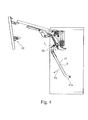
- FIG. 4 shows the opened folding furniture flap 6, wherein the actuating arm 21 with a flap-side Stellarmende 21 a detached from the support joint 22 and is aligned aus calmk to separate the actuator arm 21 from the fitting part 7 a.
- alignment of the actuating arm 21 requires manual intervention from the outside, for example, by a person (not shown), since the dissolved from the support joint 22 and hanging alone on the bayonet joint 23 on the fitting part 7 a actuating arm 21 otherwise clockwise P2 according to the bearing axis L so far would pivot until the center of gravity S of the articulated actuator arm 21 is positioned vertically below the bearing axis L of the bearing 28.
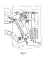
- FIG. 2a clarifies the details of the bayonet connection 23.
- the z. B. consists of a flat sheet material, a round hole 24 formed with a polygonal lug-shaped recess 25.
- the recess 25 is formed in the direction of the longitudinal extension of a body-side end piece of the actuating arm 21.
- On the fitting part 7a is complementary to the hole 24 and the recess 25 is formed in the basic form a cylindrical pin 26 with an outwardly projecting projection 27.
- the bearing 28 In the connected state of the actuating arm 21 with the fitting part 7a so that the bearing 28 is formed with the bayonet joint 23, which on the actuating arm 21 an actuating arm connecting part with the hole 24 and the recess 25th includes.
- the bearing 28 also has a connecting part on the fitting part 7a with the pin 26 and the projection 27, which together with the actuating arm connecting part form the bearing point 28.
- the connecting part on the fitting part 7a is divided into a first portion of the pin 26, which is cylindrical on its own and protrudes perpendicularly on a flat side of the fitting part 7a, which is parallel to the plane of the drawing.
- a second portion of the pin 26 which extends to the front to a free end of the pin 26 is over a circumferential range or angle ⁇ of about 40 degrees (s. FIG. 2a ) to the bearing axis L of the projection 27 is formed.
- the projection 27 is formed on the outside of the cylindrical part of the pin 26 as a projecting web with three mutually perpendicular longitudinal outer sides. The projection 27 extends in pin longitudinal direction over a partial length of the pin 26th
- FIG. 5 shows in detail the situation in the first sub-step of the assembly of the Stellarmendes 21b, after which the hole 24 with the recess 25 is exactly aligned or aligned with the pin 26th with the projection 27, so that a plug movement of the actuating arm 21 in the direction perpendicular to the plane in the first step of the assembly can be carried out.
- the actuator arm 21 and the body-side part of the bearing 28 In this position or during the insertion movement of the actuator arm 21 and the body-side part of the bearing 28 is secured against rotation about the bearing axis L, which is realized via the intermeshing parts of the projection 27 and the recess 25. But these parts allow a sliding guide in the direction of the bearing axis L.
- the actuating arm 21 is plugged so far in the direction of the fitting part 7a until the Stellarmende 21b is shifted according to its material thickness over the length of the projection 27 or until possibly one side of the Stellarmendes 21b abuts on the flat side of the fitting part 7a. Only then can the actuating arm 21 in a second sub-step of the assembly execute a rotational movement about the bearing axis L, which in the direction P2 (see FIG. FIG. 4 ) until the Stellarmende 21 a is connected to the folding flap 9 via the support joint 22.
- a rotation or pivoting of the actuating arm 21 takes place about the bearing axis L or at the bearing point 28 according to the bayonet connection 23 between the open position of the folding furniture flap 6 according to the FIGS. 1 . 2 and 2a in the direction opposite P2 to a maximum of the closed position of the folding furniture flap 6 according to FIG. 3 ,
- the actuating arm 21 is not allowed to move or release the actuating arm 21 from the bearing 28 perpendicular to the drawing plane or in the direction of the bearing axis L or mechanically blocked.
- the actuator arm 21 To disassemble the actuator arm 21, for example, in a disassembly of the furniture 1, the actuator arm 21 must be separated from the support joint 22 and then in accordance with FIG. 5 shown position to be pivoted. Then, the actuator arm 21 can be pulled away in the direction of the bearing axis L and separated from the bearing 28.
Landscapes
- Engineering & Computer Science (AREA)
- Mechanical Engineering (AREA)
- Cabinets, Racks, Or The Like Of Rigid Construction (AREA)
- Closing And Opening Devices For Wings, And Checks For Wings (AREA)
- Hinges (AREA)
Abstract
Description
- Vorrichtungen zum Bewegen einer an einem Möbelkorpus bewegbar aufgenommenen Möbelklappe sind bekannt. Derartige Vorrichtungen wirken zwischen dem Möbelkorpus und der Möbelklappe und sind als Scharniere beziehungsweise Klappenbeschläge ausgestaltet, um ein Herausschwenken der Möbelklappe aus einer Schließposition am Möbelkorpus in Richtung einer Offenstellung der Möbelklappe und zurück in die Schließposition zu ermöglichen. Bei Möbelklappen mit zwei gelenkig verbunden zusammenwirkenden Klappensegmenten muss die Vorrichtung gegenüber einer Vorrichtung für eine Einfachklappe komplexer aufgebaut sein.
- Moderne Klappenbeschläge weisen regelmäßig zusätzlich Einrichtungen wie eine Dämpferanordnung und eine Krafteinheit auf, welche die Möbelklappenbewegung beeinflussen.
- Der Erfindung liegt die Aufgabe zugrunde, einleitend genannte Vorrichtungen vorteilhaft weiter zu verbessern, insbesondere im Hinblick auf die Vermeidung von Betriebsstörungen und die Montage der Vorrichtung an dem Möbel. Diese Aufgabe wird durch die unabhängigen Ansprüche gelöst. Die abhängigen Ansprüche thematisieren vorteilhafte Weiterbildungen der Erfindung.
- Die Erfindung geht aus von einer Vorrichtung zum Bewegen einer an einem Möbelkorpus bewegbar aufgenommenen Möbelklappe mit einem oberen Klappenelement und einem unterem Klappenelement, die miteinander gekoppelt sind, wobei die Vorrichtung einen schwenkbaren Tragarm aufweist, der mit dem oberen Klappenelement verbindbar ist, und einen Stellarm der möbelkorpusseitig über eine erste Lagerstelle des Stellarms aufgenommen und mit dem unteren Klappenelement über eine zweite Lagerstelle des Stellarms verbindbar ist. Insbesondere sind die Lagerstellen durch die Vorrichtung selbst bereitgestellt. Die erfindungsgemäße Vorrichtung ist insbesondere ein Möbel-Klappenbeschlag wie ein Falt-Klappenbeschlag für zwei gelenkig zusammenwirkende Faltklappenelemente einer Möbelklappe eines Möbels. Der Klappenbeschlag kann insbesondere als 7-Gelenk oder als 4-Gelenk mit mehreren miteinander gelenkig zusammenwirkenden Gelenkarmen ausgebildet sein.
- Erfindungsgemäß sind Anbringmittel zur lösbaren Verbindung des Stellarms an einer Lagerstelle des Stellarms vorgesehen, wobei die Anbringmittel ein Stellarm-Verbindungsteil am Stellarm und ein Verbindungsteil an einem mit dem Stellarm-Verbindungsteil verbindbaren Abschnitt der Lagerstelle aufweist, und wobei die Anbringmittel derart ausgebildet sind, dass die Verbindung durch eine Kombination einer Steckbewegung und einer Drehbewegung des Stellarm-Verbindungsteils einrichtbar ist. Damit ist vorteilhaft sowohl eine einfache Anbringung als auch eine sichere Verbindung des Stellarms an der Lagerstelle möglich. Die Steck- und Drehbewegung des Stellarm-Verbindungsteils erfolgt insbesondere von Hand durch eine Person, indem der Stellarm als Ganzes entsprechend bewegt und mit dem Stellarm-Verbindungsteil an der Lagerstelle angebracht wird. Aufgrund der einfachen Montageschritte durch Stecken und Drehen ist dies selbst für Laien ohne weiteres möglich.
- Die Kombination der Steckbewegung und der Drehbewegung des Stellarm-Verbindungsteils ist vorteilhaft derart, dass zunächst allein die eine Bewegungsart und anschließend allein die andere Bewegungsart erfolgt, also zum Beispiel zunächst nur die Steckbewegung ohne Drehbewegung und anschließend nach Beendigung der Steckbewegung allein die Drehbewegung ohne eine Bewegung in Richtung der Steckbewegung erfolgt oder anders herum. Dies lässt eine besonders einfache Anbringung zu, da die translatorische bzw. lineare Steckbewegung und die rotatorische Drehbewegung nicht überlagert stattfinden, was aber nicht ausgeschlossen ist.
- Auch ist es möglich, dass die Anbringung durch eine andere Abfolge von Steck- und Drehbewegungen vornehmbar ist, beispielsweise zuerst eine erste Steckbewegung dann eine erste Drehbewegung und dann eine zweite Steckbewegung und/oder eine zweite Drehbewegung des Stellarm-Verbindungsteils umfassen, gegebenenfalls kann die zweite Drehbewegung in zur ersten Drehbewegung entgegengesetzter Drehrichtung erfolgen.
- Die erfindungsgemäße Anordnung ist insbesondere für eine Vorgehensweise bei der Montage vorteilhaft, wonach der an der betreffenden Lagerstelle anzubringende Stellarm frei beweglich bzw. noch über keine andere Lagerstelle mit dem Klappenelement oder möbelkorpusseitig verbunden ist, wie dies im vollständig montierten Zustand der Fall ist. Dadurch kann die Steck- und Drehbewegung problemlos stattfinden, insbesondere da eine entsprechende Montagebewegung des Stellarms räumlich nicht eingeschränkt ist.
- Die betreffende Lagerstelle, an welcher die Anbringung durch ein kombiniertes Anstecken und Drehen erfolgt, kann die erste oder zweite Lagerstelle des Stellarms sein. Nach der Anbringung des Stellarms an der betreffenden Lagerstelle muss der gesamte Stellarm noch räumlich so verstellt zum Beispiel insbesondere um die mit der Lagerstelle bereitgestellte Schwenkachse des Stellarmes verschwenkt werden, dass der Stellarm an der weiteren Lagerstelle angebracht werden kann. Die Anbringung an der andere Lagerstelle erfolgt in der Regel auf eine andere Art bzw. nicht mit einer kombinierten Steck- und Drehbewegung eines weiteren Stellarm-Verbindungsteils, zum Beispiel durch Aufclipsen, Aufrasten oder Anschrauben.
- Die beiden Lagerstellen des Stellarms sind jeweils insbesondere zumindest Dreh- bzw. Schwenklagerstellen.
- Die Dreh- und Steckbewegung des Stellarm-Verbindungsteils betrifft eine Montage der Vorrichtung bzw. des Stellarms am Möbel, welche z. B. bei der erstmaligen Anbringung der Vorrichtung am Möbel nötig ist. Da der Stellarm ein im Betrieb sich starr verhaltendes mechanisches Bauteil ist, ist das Stellarm-Verbindungsteil am Stellarm festgelegt vorhanden. Demgemäß wird die Steck- und Drehbewegung des Stellarm-Verbindungsteils mit einer entsprechenden Bewegung des gesamten Stellarms realisiert.
- Wenn eine Demontage des Stellarms von der Vorrichtung stattfindet, wird eine entsprechende Abfolge der Kombination der Steckbewegung und der Drehbewegung des Stellarm-Verbindungsteils in umgekehrter Reihenfolge durchgeführt, was gleichermaßen einfach und problemlos möglich ist, zum Beispiel durch eine kombinierte geringe Verdrehung und eine kurze lineare zur Steckbewegung beim Anbringen entgegengerichtete Wegziehbewegung des Stellarms bzw. des Stellarm-Verbindungsteils.
- Das mit dem Stellarm-Verbindungsteil zur Anbringung des Stellarms zusammenwirkende Verbindungsteil an der Lagerstelle ist getrennt vom Stellarm an der Vorrichtung bzw. am Möbelkorpus bzw. am Klappenelement vorhanden. Das Stellarm-Verbindungsteil und das dazugehörige Verbindungsteil sind so aufeinander abgestimmt ausgebildet, dass nur in der damit vorgegebenen Kombination bzw. Abfolge der Steck- und Drehbewegung des Stellarm-Verbindungsteils eine Anbringung des Stellarms an bzw. Abnahme von der Lagerstelle erfolgen kann. Damit wird z. B. eine versehentliche Anbringung des Stellarms in einer nicht funktionsgemäßen Ausrichtung bzw. eine Fehlmontage ausgeschlossen.
- Die erfindungsgemäße Vorrichtung weist gegebenenfalls eine Krafteinheit auf, welche im montierten Zustand der Vorrichtung eine Öffnungs- und/oder Schließbewegung der Möbelklappe durch eine von der Krafteinheit bereitstellbare Kraftwirkung zumindest unterstützt. Die Krafteinheit wirkt insbesondere am Trag- und/oder Stellarm.
- Vorteilhafterweise sind die Anbringmittel als Bajonettverschlussmittel ausgestaltet. Die Bajonettverschlussmittel umfassen sämtliche Varianten bzw. konkrete Realisierungen, welche eine Verbindung nach der Art eines Bajonettverschlusses ermöglichen. Mit den Bajonettverschlussmitteln sind die Anbringmittel platzsparend, stabil und für ein anbringen und Lösen der Verbindung funktional vorteilhaft ausgebildet.
- Weiter wird vorgeschlagen, dass die Anbringmittel zur lösbaren Verbindung des Stellarms an der möbelkorpusseitigen Lagerstelle des Stellarms vorhanden sind. Dies ist im Hinblick auf eine Montage und Demontage vorteilhaft. Das mit dem Stellarm-Verbindungsteil verbindbare Verbindungsteil der Lagerstelle kann vorteilhaft an einem Beschlagteil der Vorrichtung vorbereitet bereitgestellt werden. Das Beschlagteil umfasst die weiteren Teile der Vorrichtung und wird an dem Möbelkorpus insbesondere an einer Innenseite einer Seitenwand des Möbelkorpus angebracht. Mit der richtigen Positionierung des Beschlagteils am Möbelkorpus wird damit vorteilhaft auch das Verbindungsteil der Lagerstelle, das nicht am Stellarm ausgebildet ist, bereitgestellt.
- Es ist überdies vorteilhaft, dass die Anbringmittel derart abgestimmt sind, dass eine Einrichtung der Verbindung des Stellarms an der Lagerstelle nur in einer räumlichen Ausrichtung des Stellarms möglich ist, welche der Stellarm im montierten Zustand der Vorrichtung bei einer Bewegung der Möbelklappe nicht einnimmt. Damit wird sichergestellt, dass die Verbindung des Stellarms an der Lagerstelle, was über das Stellarm-Verbindungsteil und das Verbindungsteil erfolgt, im Betrieb der Vorrichtung nicht lösbar ist. Denn der Stellarm befindet sich in sämtlichen möglichen Betriebszuständen beim funktionsgemäßen Öffnen und Schließen der Möbelklappe in einer räumlichen Ausrichtung, welche sich von der räumlichen Ausrichtung unterscheidet, die vorausgesetzt ist, um die Verbindung des Stellarms an der Lagerstelle wieder aufzuheben. Dabei entspricht die räumliche Ausrichtung des Stellarms, die bei der Einrichtung der Verbindung an der Lagerstelle zwingend notwendig ist, der räumlichen Ausrichtung, welche zur Aufhebung der Verbindung des Stellarms an der Lagerstelle notwendig ist.
- Eine vorteilhafte Modifikation des Erfindungsgegenstandes zeichnet sich dadurch aus, dass die Anbringmittel derart ausgestaltet sind, dass eine für eine Verbindung des Stellarms an der Lagerstelle notwendige Steckbewegung des Stellarm-Verbindungsteils relativ zum Verbindungsteil der Lagerstelle nur in einer räumlichen Ausrichtung des Stellarms möglich ist, welche sich bezogen auf den montierten Zustand der Vorrichtung von sämtlichen unterschiedlichen Ausrichtungen des Stellarms unterscheidet, die der Stellarm bei einer Bewegung der Möbelklappe beim Öffnen oder Schließen der Möbelklappe einnimmt. Dies ist bezüglich einer Kombination der Steck- und der Drehbewegung des Stellarm-Verbindungsteils, bei welcher beispielsweise zuerst eine Steckbewegung erfolgt, bevor die Drehbewegung stattfindet bzw. stattfinden kann, vorteilhaft. Der Verbindungsvorgang ist dabei z. B. derart, dass beim Zusammenbringen des Stellarm-Verbindungsteils und des damit zusammenwirkenden Verbindungsteils an der Lagerstelle erst mit der Steckbewegung beginnt, welche nur bei positionsrichtiger Ausrichtung der betreffenden Abschnitte am Stellarm und dem dazugehörigen Verbindungsteil möglich ist. Demgemäß ist die Steckbewegung Voraussetzung dafür bzw. stellt den initiierenden Vorgang dar, der obligatorisch erfüllt sein muss, bevor die nachfolgende Phase des Verbindungsvorgangs mit der Drehbewegung beginnen kann. Bezogen auf das dazugehörige Verbindungsteil an der Lagerstelle ist ein Verdrehen des Stellarm-Verbindungsteils erst dann möglich, wenn zuvor die Steckbewegung abgeschlossen ist. Damit ist auch klar, dass mit dem in diesem Zusammenhang genannten Verdrehen des Stellarm-Verbindungsteils ein Verdrehen gemeint ist, welches zur mit den Anbringmitteln realisierbaren Verbindung des Stellarms beiträgt. Dies bedeutet, dass das Verdrehen ein funkrichtiges Zusammenwirken von Stellarm-Verbindungsteil und dem dazugehörigen Verbindungsteil an der Lagerstelle voraussetzt und z. B. nicht ein irgendwie geartetes Verdrehen des Stellarm-Verbindungsteils betrifft, was nicht im funktionsrichtigen Zusammenspiel mit der Lagerstelle erfolgt.
- Mit den wie vorgenannt ausgestalteten Anbringmitteln bzw. Bajonett-Verschlussmitteln wird sicher ausgeschlossen, dass im Betrieb beim Bewegen der Möbelklappe der Stellarm sich von der betreffenden insbesondere möbelkorpusseitigen Lagerstelle trennt. Voraussetzung ist, dass der Stellarm zumindest eine räumliche Ausrichtung kennt, in welcher das Stellarm-Verbindungsteil relativ zum dazugehörigen Verbindungsteil an der Lagerstelle bringbar ist, die sich von sämtlichen räumlichen Ausrichtungen des Stellarms beim Bewegen der Möbelklappe im Betrieb der Vorrichtung unterscheidet. Diese auch als z. B. Montageausrichtung bezeichnete Ausrichtung ist insbesondere nur dann möglich, wenn der zu montierende Stellarm an der anderen Lagerstelle nicht aufgenommen ist.
- Das Anbringen an der anderen Lagerstelle, was insbesondere über nicht erfindungsgemäße bzw. bekannte Anbringmittel erfolgt, findet für erfindungsgemäße Varianten grundsätzlich erst statt, wenn die Lagerstelle des Stellarms mit den erfindungsgemäßen Anbringmitteln vollständig eingerichtet ist.
- Des Weiteren ist es vorteilhaft, dass die Anbringmittel einen Zapfenabschnitt mit einem zu einer Lagerachse der Lagerstelle radial nach außen vorstehenden Vorsprung am mit dem Stellarm-Verbindungsteil verbindbaren Abschnitt der Lagerstelle umfassen. Dies ist kompakt und einfach realisierbar.
- Vorteilhaft weisen die Anbringmittel am Stellarm-Verbindungsteil eine Öffnung auf, welche zur Lagerachse eine radial nach außen vorspringende Ausnehmung aufweist.
- Demgemäß ist es vorteilhaft, dass ein Zapfenabschnitt mit einem zu einer Lagerachse der Lagerstelle radial nach außen vorstehenden Vorsprung am mit dem Stellarm-Verbindungsteil verbindbaren Abschnitt der Lagerstelle vorhanden ist, und am Stellarm-Verbindungsteil eine auf den Zapfenabschnitt abgestimmte Öffnung existiert, welche zur Lagerachse eine radial nach außen vorspringende Ausnehmung aufweist, wobei die Öffnung für ein Aufstecken auf den Zapfenabschnitt abgestimmt ist, so dass der Vorsprung passend durch die Ausnehmung greift.
- Der Vorsprung ist insbesondere nur über einen Teil der Länge des Zapfenabschnitts vorhanden. Der Zapfenabschnitt weist neben dem Abschnitt mit dem Vorsprung einen Abschnitt insbesondere in einer schlanken bzw. länglichen Form auf, welche gegenüber dem Vorsprung radial zur Längsachse des Zapfenabschnitts zurückversetzt ist. Der Abschnitt in länglicher Form ist z. B. zylindrisch oder anders regelmäßig z. B. mehrkantartig geformt. Vom freien Ende des Zapfenabschnitts aus betrachtet schließt sich an den Bereich mit dem Vorsprung ein Abschnitt ohne Vorsprung an. Die richtige Ausrichtung des Stellarms beim Aufstecken des Stellarms bzw. des Stellarm-Verbindungsteils am Zapfenabschnitt ergibt sich aus der Stellung, in welcher die Aussparung passend über den Vorsprung aufschiebbar ist.
- Damit ist das Stellarm-Verbindungsteil und der mit dem Stellarm-Verbindungsteil verbindbare Abschnitt der Lagerstelle nach dem Schlüssel-Schloss-Prinzip ausbildbar. Die Öffnung mit der Ausnehmung am Stellarm-Verbindungsteil ist in Form und Größe vorteilhaft komplementär zum Zapfenabschnitt mit dem Vorsprung ausgebildet. Insbesondere stimmt der Umriss der Öffnung mit der Ausnehmung und der Umriss des Zapfenabschnitts mit dem Vorsprung zumindest im Wesentlichen überein bzw. ist ggf. derart, dass bei der Steckbewegung des Stellarms bzw. des Stellarm-Verbindungsteils sich ein geringes Spiel bzw. geringer Luftspalt zwischen den Umrissen der Öffnung mit der Ausnehmung einerseits und dem Zapfenabschnitt mit dem Vorsprung andererseits ergibt. Beim Einrichten der Verbindung des Stellarms wird dieser so ausgerichtet an den dazugehörigen Abschnitt der Lagerstelle herangeführt, dass die Öffnung auf den Zapfenabschnitt mit der Steckbewegung aufsteckbar ist, wobei das Stellarm-Verbindungsteil mit der Öffnung etwas in Richtung der Längsachse des Zapfenabschnitts verschoben wird. Dies ist vorteilhaft nur in einer einzigen Stellung bzw. Drehstellung des Stellarm-Verbindungsteils zum dazugehörigen Abschnitt der Lagerstelle möglich, in welcher die Ausnehmung passend über den bzw. am Vorsprung entlang geschoben wird, ohne dass die Ränder der Ausnehmung und des Vorsprungs aneinander anstoßen, was andernfalls eine Steckbewegung blockieren würde.
- Das Entlangschieben des Stellarm-Verbindungsteils erfolgt so weit, bis die Ausnehmung den Vorsprung passiert hat. Im Anschluss daran folgt die Drehbewegung des Stellarm-Verbindungsteils und damit des Stellarms selbst, so dass die Ausnehmung in Steckrichtung hinter dem Vorsprung relativ zum Vorsprung verdreht wird. Dadurch kann der Stellarm nicht mehr entgegen der Steckrichtung bewegt und damit nicht von der Lagerstelle gelöst bzw. entfernt werden. Dies ist erst dann wieder möglich, wenn der Stellarm mit dem Stellarm-Verbindungsteils bzw. die Ausnehmung wieder relativ zum Zapfenabschnitt zurückgedreht wird, so dass die Ausnehmung exakt fluchtend zum Vorsprung gelangt. Die Abmessung der Ausnehmung bzw. entsprechend die Abmessung des Vorsprungs in zur Lagerachse bzw. in Steckrichtung umfänglicher Richtung ist zur gesamten umfänglichen Abmessung nur über einen Teilumfang ausgebildet bzw. insbesondere vergleichsweise schmal, zum Beispiel über ca. 40 bis 80 Winkelgrade ausgestaltet.
- Auch ist es von Vorteil, dass die Öffnung am Stellarm-Verbindungsteil für ein Aufstecken des Stellarm-Verbindungsteils auf den Zapfenabschnitt derart ausgerichtet am Stellarm-Verbindungsteil vorhanden ist, dass der Stellarm nur in einer vorgebbaren Ausrichtung an der möbelkorpusseitigen Lagerstelle anbringbar ist, wobei die vorgebbare Ausrichtung keine im Betrieb der Vorrichtung zum Bewegen der Möbelklappen vom Stellarm einnehmbare Ausrichtung ist.
- Bei einer vorteilhaften Variante der Erfindung ist ein möbelkorpusseitig montierbares Grundbauteil vorhanden, welches den mit dem Stellarm-Verbindungsteil verbindbaren Abschnitt der möbelkorpusseitigen Lagerstelle des Stellarms umfasst. Mit dem Grundbauteil können herstellerseitig die wesentlichen bzw. sämtlichen möbelkorpusseitigen Teile der Vorrichtung bzw. des Klappenbeschlags an einem Bauteil bereitgestellt werden. Nach der Montage des Grundbauteils an dem Möbelkorpus ist die Verbindung mit der Möbelklappe bzw. den Klappenelementen über gelenkige Elemente der Vorrichtung wie insbesondere Scharnierarme vorzunehmen.
- Schließlich ist die erfindungsgemäße Vorrichtung vorteilhaft derart gestaltet, dass eine Anordnung mit einer Dämpferanordnung zur Dämpfung der Bewegung des bewegbaren Möbelteils vorgesehen ist, wobei die Dämpferanordnung einen Dämpfer aufweist, wobei für eine Dämpfwirkung der Dämpfanordnung ein zeitweiser Kontakt des Dämpfers mit einem bewegbaren Gegenabschnitt der Vorrichtung stattfindet, und wobei im montierten Zustand der Vorrichtung eine Bewegung des Gegenabschnittes abhängig von einer Bewegung des Möbelteils erfolgt. Damit kann die Bewegung des bewegbaren Möbelteils beziehungsweise der Möbelklappe bei einer Öffnungs- und/oder Schließbewegung des Möbelklappenelements vorteilhaft gedämpft erfolgen. Die Dämpfung der Bewegung kann insbesondere vor dem Erreichen einer vollständig geschlossenen beziehungsweise vollständige geöffneten Stellung der Möbelklappe relativ zum Möbelkorpus eingerichtet werden. Dadurch können Anschlaggeräusche bzw. Beschädigungen am Möbel und der Vorrichtung vermieden werden.
- Der Dämpfer ist insbesondere als Fluid-Dämpfer wie beispielsweise als Luft- beziehungsweise Öl-Dämpfer ausgestaltet.
- Die Erfindung betrifft außerdem ein Möbel mit einer an einem Möbelkorpus aufgenommenen Möbelklappe mit einem oberen Klappenelement und einem unterem Klappenelement, die miteinander gekoppelt sind, wobei die Möbelklappe in eine Öffnungsrichtung und in eine Schließrichtung relativ zum Möbelkorpus bewegbar ist, wobei eine Vorrichtung nach einem der oben genannten Ausbildungen vorgesehen ist. Damit kann ein Möbel mit einer Möbelklappe bereitgestellt werden, bei dem die erläuterten Vorteile erzielbar sind.
- Weitere Merkmale und Vorteile der Erfindung sind anhand eines erfindungsgemäßen Ausführungsbeispiels näher erläutert.
- Im Einzelnen zeigt:
- Figur 1
- eine erfindungsgemäße Vorrichtung von der Seite im an einer Seitenwand eines Möbelkorpus montierten und mit einer Möbelklappe verbundenen Zustand bei vollständig geöffneter Möbelklappe,
- Figur 2
- einen Ausschnitt der Anordnung gemäß
Figur 1 , - Figur 2a
- den in
Figur 2 mit A bezeichneten Bereich in vergrößerter Detailansicht, - Figur 3
- einen Ausschnitt der Anordnung gemäß
Figur 1 , bei vollständig geschlossener Möbelklappe, - Figur 4
- die Anordnung gemäß
Figur 1 mit möbelklappenseitig ausgehängtem Stellarm und - Figur 5
- die Anordnung gemäß
Figur 4 jedoch bei geschlossener Möbelklappe. -
Figur 1 zeigt einen Teil eines Möbels 1 mit einem Möbelkorpus 2, von dem lediglich eine Seitenwand 3 von zwei gleichartigen vertikalen Seitenwänden gezeigt ist. Der Möbelkorpus 2 umfasst zwischen den Seitenwänden ein horizontales unteres Bodenteil 4 und ein oberes Deckelteil 5. Außerdem ist eine gegebenenfalls vorhandene Rückwand des Möbelkorpus 2 ebenfalls nicht dargestellt. Innen an der Seitenwand 3 ist unterhalb des Deckelteils 5 eine erfindungsgemäße Vorrichtung zum Bewegen einer Falt-Möbelklappe 6 montiert, welche als Möbelbeschlag bzw. als Klappenbeschlag 7 zum Verschwenken der Falt-Möbelklappe 6 relativ zum Möbelkorpus 2 ausgebildet ist. Mit der Falt-Möbelklappe 6 kann eine vorderseitige Öffnung 2a des Möbelkorpus 2 abgedeckt oder freigegeben werden, so dass bei geöffneter Falt-Möbelklappe 6 gemäßFigur 1 ein Innenvolumen des Möbelkorpus 2 von vorne gemäß Richtung P1 zugänglich ist. - Zur sicheren Halterung und Bewegung der Falt-Möbelklappe 6 am Möbelkorpus 2 ist innen an der gegenüberliegenden nicht dargestellten Seitenwand in der Regel ein weiterer zwischen dem Möbelkorpus 2 und der Falt-Möbelklappe 6 wirkender Klappenbeschlag vorhanden, der dem Klappenbeschlag 7 in Aufbau und Funktion entspricht.
- Die Falt-Möbelklappe 6 ist aus zwei Klappenelementen mit einer oberen Faltklappe 8 und einer unteren Faltklappe 9 aufgebaut. Zwischen dem unteren Bereich der Faltklappe 8 und dem oberen Bereich der Faltklappe 9 ist innenseitig eine Gelenkanordnung 10 vorhanden, über welche die Faltklappen 8 und 9 miteinander gelenkig verbunden sind.
- Der erfindungsgemäße Klappenbeschlag 7, der als Mehrfachgelenk hier beispielsweise als 7-Gelenk ausgebildet ist, weist ein an der Innenseite der Seitenwand 3 montiertes Beschlagteil 7a und ein innen an einer oberen Faltklappe 8 angebrachtes Halteteil 7b mit dazwischen wirkenden Gelenkelementen auf. Die Gelenkelemente umfassen gelenkig wirkende Tragarme 17 und 18 und Zwischenarme 19 und 20, welche zur Schwenkbewegung der oberen Faltklappe 8 dienen.
- Anstelle des Klappenbeschlags 7 könnte grundsätzlich auch ein Klappenbeschlag, der als 4-Gelenk aufgebaut ist, vorgesehen sein.
- Des Weiteren umfasst der Klappenbeschlag 7 zur beweglichen Führung der unteren Faltklappe 9 einen als Stellarm 21 ausgestalteten Steuerhebel für die untere Faltklappe 9, der gelenkig einerseits über eine Lagerstelle 28 möbelkorpusseitig und andererseits über eine weitere Lagerstelle bzw. ein Haltegelenk 22 bzw. einen Gelenkbeschlag innenseitig an der unteren Faltklappe 9 aufgenommen ist.
- Außerdem ist der Klappenbeschlag 7 mit einer Dämpferanordnung umfassend einen Dämpfer 12 und mit einer Krafteinheit 11 zur kraftunterstützten Bewegung einer Öffnungs- und/oder Schließbewegung der Falt-Möbelklappe 6 versehen. Die mit drei Schraubenfedern bestückte Krafteinheit 11 ist nicht näher erläutert.
- Die Dämpferanordnung dient zur Dämpfung der Schließ- und/oder Öffnungsbewegung der Falt-Möbelklappe 6 mittels des Klappenbeschlags 7, insbesondere vor Erreichen einer vollständig geöffneten bzw. geschlossenen Endstellung der Falt-Möbelklappe 6 relativ zum Möbelkorpus 2.
- Der Dämpfer 12 ist hier beispielhaft als Fluiddämpfer bzw. als Gas- oder Öldämpfer ausgebildet. Der Dämpfer 12 umfasst ein Dämpfergehäuse 13 und einen dazu relativ verschieblichen Dämpferkolben 14. Des Weiteren ist ein Lagergehäuse 15 vorgesehen, in dem das Dämpfergehäuse 13 und damit der Dämpfer 12 verschieblich am Beschlagteil 7a gelagert ist. Diesbezüglich sind zusätzlich Verstellmittel 16 zur Verstellung der räumlichen Ausrichtung des Lagergehäuses 15 samt dem Dämpfer 12 vorhanden. Das Lagergehäuse 15 ist mittels eines Schwenklagers schwenkbar am Beschlagteil 7a gelagert. Die Verstellmittel 16 umfassen ein Verstellelement 16a, das mit dem Lagergehäuse 15 bewegungsgekoppelt ist, so dass die Verstellung mit einer Schwenkbewegung des Lagergehäuses 15 erfolgt, wobei eine Schwenkbewegung des Verstellelements 16a auf das Lagergehäuse 15 übertragbar ist, womit der Dämpfer 12 in verschiedene Ausrichtungen bringbar ist.
- Die komplett geöffnete Falt-Möbelklappe 6 zeigt
Figur 1 , wobei die obere Faltklappe 8 zur Horizontalen etwas nach oben abgewinkelt ist und die untere Faltklappe 9 über die Gelenkanordnung 10 bezogen auf die Vertikale etwas nach innen Richtung Möbelkorpus 2 geneigt ausgerichtet ist. Im komplett geschlossenen Zustand der Falt-Möbelklappe 6, gemäßFigur 3 sind die Faltklappen 8 und 9 fluchtend zueinander vertikal ausgerichtet. - Der Stellarm 21 ist korpusseitig über Anbringmittel, mit denen eine Bajonettverbindung 23 ausgebildet ist, am Beschlagteil 7a aufgenommen. Die Bajonettverbindung 23 ist durch eine kombinierte Steck- und Drehbewegung des Stellarms 21 bzw. dessen korpusseitigem Stellarmende 21b einrichtbar bzw. wieder aufhebbar.
-
Figur 4 zeigt die geöffnete Falt-Möbelklappe 6, wobei der Stellarm 21 mit einem klappenseitigen Stellarmende 21a vom Haltegelenk 22 gelöst und aushängebereit ausgerichtet ist, um den Stellarm 21 vom Beschlagteil 7a zu trennen. Die inFigur 4 gezeigte Ausrichtung des Stellarms 21 bedarf eines manuellen Einwirkens von außen zum Beispiel durch eine Person (nicht gezeigt), da der vom Haltegelenk 22 gelöste und allein über die Bajonettverbindung 23 am Beschlagteil 7a hängende Stellarm 21 ansonsten im Uhrzeigersinn gemäß P2 um die Lagerachse L so weit schwenken würde, bis der Schwerpunkt S des ausgependelten Stellarms 21 vertikal unter der Lagerachse L der Lagerstelle 28 positioniert ist. -
Figur 2a verdeutlicht die Einzelheiten der Bajonettverbindung 23. Am Stellarm 21 ist am korpusseitigen Ende, das z. B. aus einem flachen Blechmaterial besteht, ein rundes Loch 24 mit einer eckigen laschenförmigen Aussparung 25 ausgebildet. Die Aussparung 25 ist in Richtung der Längserstreckung eines korpusseitigen Endstücks des Stellarms 21 ausgebildet. Am Beschlagteil 7a ist komplementär zum Loch 24 und der Aussparung 25 ein in der Grundform zylindrischer Zapfen 26 mit einem nach außen vorstehenden Vorsprung 27 ausgebildet. Im verbundenen Zustand des Stellarms 21 mit dem Beschlagteil 7a wird damit die Lagerstelle 28 mit der Bajonettverbindung 23 gebildet, welche am Stellarm 21 ein Stellarm-Verbindungsteil mit dem Loch 24 und der Aussparung 25 umfasst. Die Lagerstelle 28 weist außerdem ein Verbindungsteil am Beschlagteil 7a auf mit dem Zapfen 26 und dem Vorsprung 27, die mit dem Stellarm-Verbindungsteil zusammen die Lagerstelle 28 bilden. - Das Verbindungsteil am Beschlagteil 7a unterteilt sich in einen ersten Abschnitt des Zapfens 26, der allein zylindrisch ist und an einer flachen Seite des Beschlagteils 7a, welche parallel zur Zeichenebene liegt, senkrecht vorsteht. Am zweiten Abschnitt des Zapfens 26, der sich bis vorne zu einem freien Ende des Zapfens 26 erstreckt ist über einen umfänglichen Bereich bzw. Winkel α von ca. 40 Winkelgraden (s.
Figur 2a ) zur Lagerachse L der Vorsprung 27 ausgebildet. Der Vorsprung 27 ist außen am zylindrischen Teil des Zapfens 26 als vorstehender Steg mit drei rechtwinklig zueinander ausgerichteten Längs-Außenseiten gebildet. Der Vorsprung 27 verläuft in Zapfen-Längsrichtung über eine Teillänge des Zapfens 26. - Zur manuellen Montage des Stellarms 21 am korpusseitigen Teil der Lagerstelle 28 am vorbereitet an der Seitenwand 3 angebrachtem Beschlagteil 7a wird der Stellarm 21 bzw. das korpusseitige Stellarmende 21b in die räumliche Ausrichtung gemäß der
Figuren 4 bzw. 5 gebracht. Diese Stellung erreicht der Stellarm 21 beim funktionsrichtigen Bewegen der Falt-Möbelklappe 6 in die geöffnete Endstellung gemäßFigur 1 und zurück in die geschlossene Endstellung gemäßFigur 3 nicht. Zur z. B. erstmaligen Montage des Stellarms 21 muss dieser daher vom Haltegelenk 22 getrennt bzw. ausgehängt sein, nur so kann der Stellarm 21 an der Lagerstelle 28 angebracht werden. Dies verdeutlichtFigur 4 und5 , welche den Stellarm 21 bzw. ein in der zur Montage notwendigen Ausrichtung zeigt, womit klar wird, dass diese Ausrichtung des Stellarms 21 nur möglich ist, wenn das klappenseitige Stellarmende 21a am Haltegelenk 22 nicht verbunden ist bzw. von diesem gelöst ist. -
Figur 5 zeigt im Detail die Situation beim ersten Teilschritt der Montage des Stellarmendes 21b, wonach das Loch 24 mit der Aussparung 25 exakt ausgerichtet bzw. fluchtend zum Zapfen 26 mit dem Vorsprung 27 ist, so dass eine Steckbewegung des Stellarms 21 in Richtung senkrecht zur Zeichenebene in dem ersten Teilschritt der Montage erfolgen kann. In dieser Stellung bzw. während der Steckbewegung ist der Stellarm 21 und der korpusseitige Teil der Lagerstelle 28 gegen Verdrehen um die Lagerachse L gesichert, was über die ineinandergreifenden Teile des Vorsprungs 27 und der Aussparung 25 realisiert ist. Diese Teile ermöglichen aber eine Schiebeführung in Richtung der Lagerachse L. - Der Stellarm 21 wird so weit in Richtung zum Beschlagteil 7a hin aufgesteckt, bis das Stellarmende 21b entsprechend seiner Materialdicke über die Länge des Vorsprungs 27 verschoben ist bzw. bis ggf. eine Seite des Stellarmendes 21b an der flachen Seite des Beschlagteils 7a anstößt. Erst dann kann der Stellarm 21 in einem zweiten Teilschritt der Montage eine Drehbewegung um die Lagerachse L ausführen, was in Richtung P2 (s.
Figur 4 ) so weit erfolgt, bis das Stellarmende 21a mit der Faltklappe 9 über das Haltegelenk 22 verbindbar ist. - Damit ist die Montage des Stellarms 21 am Beschlagteil 7a mit einer Kombination einer Steckbewegung und einer anschließenden Drehbewegung vorteilhaft realisierbar.
- Im Betrieb des Klappenbeschlags 7 erfolgt ein Drehen bzw. Schwenken des Stellarms 21 um die Lagerachse L bzw. an der Lagerstelle 28 gemäß der Bajonettverbindung 23 zwischen der Offenstellung der Falt-Möbelklappe 6 gemäß der
Figuren 1 ,2 und2a in Richtung entgegen P2 bis maximal zur Schließstellung der Falt-Möbelklappe 6 gemäßFigur 3 . Dabei ist beim im Nutzbetrieb maximal weit in Schließrichtung verschwenkten Stellarm 21 bei geschlossener Falt-Möbelklappe 6 ein Wegziehen bzw. Lösen des Stellarms 21 von der Lagerstelle 28 senkrecht zur Zeichenebene bzw. in Richtung der Lagerachse L nicht möglich bzw. mechanisch blockiert. Dies wird dadurch erreicht, dass in sämtlichen Stellungen des Stellarms 21 im Betriebszustand, also verbunden mit der Faltklappe 9 und dem Beschlagteil 7a, einschließlich in der Schließstellung gemäßFigur 3 , die Aussparung 25 am Loch 24 am Stellarmende 21b nicht passend bzw. versetzt zum Vorsprung 27 am Zapfen 26 ist und somit der Stellarm 21 an der Lagerstelle 28 zwar um die Lagerachse L schwenkbar bzw. verdrehbar ist aber nicht parallel zur bzw. entlang der Lagerachse L wegziehbar ist. Dementsprechend ist der Vorsprung 27 abgestimmt auf die Aussparung 25 bzw. den Stellarm 21 ausgerichtet vorhanden, hier senkrecht nach unten vorstehend am Zapfen 26. - Zur Demontage des Stellarms 21 zum Beispiel bei einem Auseinanderbau des Möbels 1, muss der Stellarm 21 vom Haltegelenk 22 getrennt und dann in die gemäß
Figur 5 gezeigte Stellung verschwenkt werden. Dann kann der Stellarm 21 in Richtung der Lagerachse L weggezogen und von der Lagerstelle 28 getrennt werden. -
- 1
- Möbel
- 2
- Möbelkorpus
- 2a
- Öffnung
- 3
- Seitenwand
- 4
- Bodenteil
- 5
- Deckelteil
- 6
- Falt-Möbelklappe
- 7
- Klappenbeschlag
- 7a
- Beschlagteil
- 7b
- Halteteil
- 8
- Faltklappe
- 9
- Faltklappe
- 10
- Gelenkanordnung
- 11
- Krafteinheit
- 12
- Dämpfer
- 13
- Dämpfergehäuse
- 14
- Dämpferkolben
- 15
- Lagergehäuse
- 16
- Verstellmittel
- 16a
- Verstellelement
- 17
- Tragarm
- 18
- Tragarm
- 19
- Zwischenarm
- 20
- Zwischenarm
- 21
- Stellarm
- 21a
- Stellarmende
- 21b
- Stellarmende
- 22
- Haltegelenk
- 23
- Bajonettverbindung
- 24
- Loch
- 25
- Aussparung
- 26
- Zapfen
- 27
- Vorsprung
- 28
- Lagerstelle
Claims (12)
- Vorrichtung (7) zum Bewegen einer an einem Möbelkorpus (2) bewegbar aufgenommenen Möbelklappe (6) mit einem oberen Klappenelement (8) und einem unteren Klappenelement (9), die miteinander gekoppelt sind, wobei die Vorrichtung (7) einen schwenkbaren Tragarm (17, 18) aufweist, der mit dem oberen Klappenelement (8) verbindbar ist, und einen Stellarm (21), der möbelkorpusseitig über eine erste Lagerstelle (28) des Stellarms (21) aufgenommen und mit dem unteren Klappenelement (9) über eine zweite Lagerstelle des Stellarms (21) verbindbar ist, dadurch gekennzeichnet, dass Anbringmittel zur lösbaren Verbindung des Stellarms (21) an einer Lagerstelle (28) des Stellarms (21) vorgesehen sind, wobei die Anbringmittel ein Stellarm-Verbindungsteil am Stellarm (21) und ein Verbindungsteil an einem mit dem Stellarm-Verbindungsteil verbindbaren Abschnitt der Lagerstelle (28) aufweist, und wobei die Anbringmittel derart ausgebildet sind, dass die Verbindung durch eine Kombination einer Steckbewegung und einer Drehbewegung des Stellarm-Verbindungsteils einrichtbar ist.
- Vorrichtung nach Anspruch 1, dadurch gekennzeichnet, dass die Anbringmittel als Bajonettverschlussmittel ausgestaltet sind.
- Vorrichtung nach Anspruch 1 oder Anspruch 2, dadurch gekennzeichnet, dass die Anbringmittel zur lösbaren Verbindung des Stellarms (21) an der möbelkorpusseitigen Lagerstelle (28) des Stellarms (21) vorhanden sind.
- Vorrichtung nach einem der vorhergehenden Ansprüche, dadurch gekennzeichnet, dass die Anbringmittel derart abgestimmt sind, dass eine Einrichtung der Verbindung des Stellarms (21) an der Lagerstelle (28) nur in einer räumlichen Ausrichtung des Stellarms (21) möglich ist, welche der Stellarm (21) im montierten Zustand der Vorrichtung (7) bei einer Bewegung der Möbelklappe (6) nicht einnimmt.
- Vorrichtung nach einem der vorhergehenden Ansprüche, dadurch gekennzeichnet, dass die Anbringmittel derart ausgestaltet sind, dass eine für eine Verbindung des Stellarms (21) an der Lagerstelle (28) notwendige Steckbewegung des Stellarm-Verbindungsteils relativ zum Verbindungsteil der Lagerstelle nur in einer räumlichen Ausrichtung des Stellarms (21) möglich ist, welche sich bezogen auf den montierten Zustand der Vorrichtung (7) von sämtlichen unterschiedlichen Ausrichtungen des Stellarms (21) unterscheidet, die der Stellarm (21) bei einer Bewegung der Möbelklappe (6) beim Öffnen oder Schließen der Möbelklappe (6) einnimmt.
- Vorrichtung nach einem der vorhergehenden Ansprüche, dadurch gekennzeichnet, dass die Anbringmittel einen Zapfenabschnitt (26) mit einem zu einer Lagerachse der Lagerstelle (28) radial nach außen vorstehenden Vorsprung (27) am mit dem Stellarm-Verbindungsteil verbindbaren Abschnitt der Lagerstelle (28) umfassen.
- Vorrichtung nach einem der vorhergehenden Ansprüche, dadurch gekennzeichnet, dass die Anbringmittel am Stellarm-Verbindungsteil eine Öffnung (24) aufweisen, welche zur Lagerachse eine radial nach außen vorspringende Ausnehmung (25) aufweist.
- Vorrichtung nach einem der vorhergehenden Ansprüche, dadurch gekennzeichnet, dass ein Zapfenabschnitt (26) mit einem zu einer Lagerachse der Lagerstelle (28) radial nach außen vorstehenden Vorsprung (27) am mit dem Stellarm-Verbindungsteil verbindbaren Abschnitt der Lagerstelle (28) vorhanden ist, und am Stellarm-Verbindungsteil eine auf den Zapfenabschnitt (26) abgestimmte Öffnung (24) existiert, welche zur Lagerachse eine radial nach außen vorspringende Ausnehmung (25) aufweist, wobei die Öffnung (24) für ein Aufstecken auf den Zapfenabschnitt (26) abgestimmt ist, so dass der Vorsprung (27) passend durch die Ausnehmung (25) greift.
- Vorrichtung nach einem der vorhergehenden Ansprüche, dadurch gekennzeichnet, dass die Öffnung (24) am Stellarm-Verbindungsteil für ein Aufstecken des Stellarm-Verbindungsteils auf den Zapfenabschnitt (26) derart ausgerichtet am Stellarm-Verbindungsteil vorhanden ist, dass der Stellarm (21) nur in einer vorgebbaren Ausrichtung an der möbelkorpusseitigen Lagerstelle (28) anbringbar ist, wobei die vorgebbare Ausrichtung keine im Betrieb der Vorrichtung (7) zum Bewegen der Möbelklappe vom Stellarm (21) einnehmbare Ausrichtung ist.
- Vorrichtung nach einem der vorhergehenden Ansprüche, dadurch gekennzeichnet, dass ein möbelkorpusseitig montierbares Grundbauteil (7a) vorhanden ist, welches den mit dem Stellarm-Verbindungsteil verbindbaren Abschnitt der möbelkorpusseitigen Lagerstelle (28) des Stellarms (21) umfasst.
- Vorrichtung nach einem der vorhergehenden Ansprüche, dadurch gekennzeichnet, dass eine Dämpferanordnung zur Dämpfung der Bewegung der bewegbaren Möbelklappe (6) vorgesehen ist, wobei die Dämpferanordnung einen Dämpfer (12) aufweist, wobei für eine Dämpfwirkung der Dämpferanordnung ein zeitweiser Kontakt des Dämpfers (12) mit einem bewegbaren Gegenabschnitt der Vorrichtung (7) stattfindet, und wobei im montierten Zustand der Vorrichtung (7) eine Bewegung des Gegenabschnitts abhängig von einer Bewegung der Möbelklappe (6) erfolgt.
- Möbel (1) mit einer an einem Möbelkorpus (2) aufgenommenen Möbelklappe (6) mit einem oberen Klappenelement (8) und einem unteren Klappenelement (9), die miteinander gekoppelt sind, wobei die Möbelklappe (6) in eine Öffnungsrichtung und in eine Schließrichtung relativ zum Möbelkorpus (2) bewegbar ist, wobei eine Vorrichtung (7) nach einem der vorhergehenden Ansprüche vorhanden ist.
Applications Claiming Priority (1)
| Application Number | Priority Date | Filing Date | Title |
|---|---|---|---|
| DE202014102478.6U DE202014102478U1 (de) | 2014-05-27 | 2014-05-27 | Vorrichtung zum Bewegen einer Möbelklappe und Möbel |
Publications (2)
| Publication Number | Publication Date |
|---|---|
| EP2949846A1 true EP2949846A1 (de) | 2015-12-02 |
| EP2949846B1 EP2949846B1 (de) | 2020-02-12 |
Family
ID=53298127
Family Applications (1)
| Application Number | Title | Priority Date | Filing Date |
|---|---|---|---|
| EP15167464.5A Active EP2949846B1 (de) | 2014-05-27 | 2015-05-13 | Vorrichtung zum bewegen einer möbelklappe und möbel |
Country Status (2)
| Country | Link |
|---|---|
| EP (1) | EP2949846B1 (de) |
| DE (1) | DE202014102478U1 (de) |
Cited By (2)
| Publication number | Priority date | Publication date | Assignee | Title |
|---|---|---|---|---|
| DE102017114775A1 (de) * | 2017-07-03 | 2019-01-03 | Hettich-Oni Gmbh & Co. Kg | Klappenbeschlag und Möbel |
| DE102017114776A1 (de) * | 2017-07-03 | 2019-01-03 | Hettich-Oni Gmbh & Co. Kg | Dämpferanordnung und Klappenbeschlag |
Families Citing this family (3)
| Publication number | Priority date | Publication date | Assignee | Title |
|---|---|---|---|---|
| DE102016100606B8 (de) * | 2016-01-14 | 2017-08-10 | Flap Competence Center Kft | Deckelsteller |
| CN107461100A (zh) * | 2017-08-21 | 2017-12-12 | 广东东泰五金精密制造有限公司 | 一种家具上翻装置的弹性作用力结构 |
| DE102023105221A1 (de) * | 2023-03-02 | 2024-09-05 | Hettich-Oni Gmbh & Co. Kg | Möbel |
Citations (2)
| Publication number | Priority date | Publication date | Assignee | Title |
|---|---|---|---|---|
| WO2006053352A1 (de) * | 2004-11-18 | 2006-05-26 | Julius Blum Gmbh | Stellantrieb |
| DE102006043186A1 (de) * | 2006-09-14 | 2008-03-27 | Webasto Ag | Gelenkeinrichtung |
Family Cites Families (1)
| Publication number | Priority date | Publication date | Assignee | Title |
|---|---|---|---|---|
| DE202010015092U1 (de) * | 2010-11-04 | 2012-02-06 | Grass Gmbh | Möbelbeschlag und Möbel |
-
2014
- 2014-05-27 DE DE202014102478.6U patent/DE202014102478U1/de not_active Expired - Lifetime
-
2015
- 2015-05-13 EP EP15167464.5A patent/EP2949846B1/de active Active
Patent Citations (2)
| Publication number | Priority date | Publication date | Assignee | Title |
|---|---|---|---|---|
| WO2006053352A1 (de) * | 2004-11-18 | 2006-05-26 | Julius Blum Gmbh | Stellantrieb |
| DE102006043186A1 (de) * | 2006-09-14 | 2008-03-27 | Webasto Ag | Gelenkeinrichtung |
Cited By (3)
| Publication number | Priority date | Publication date | Assignee | Title |
|---|---|---|---|---|
| DE102017114775A1 (de) * | 2017-07-03 | 2019-01-03 | Hettich-Oni Gmbh & Co. Kg | Klappenbeschlag und Möbel |
| DE102017114776A1 (de) * | 2017-07-03 | 2019-01-03 | Hettich-Oni Gmbh & Co. Kg | Dämpferanordnung und Klappenbeschlag |
| US11098516B2 (en) | 2017-07-03 | 2021-08-24 | Hettich-Oni Gmbh & Co. Kg | Damper assembly and flap fitting |
Also Published As
| Publication number | Publication date |
|---|---|
| EP2949846B1 (de) | 2020-02-12 |
| DE202014102478U1 (de) | 2015-08-28 |
Similar Documents
| Publication | Publication Date | Title |
|---|---|---|
| EP3198097B1 (de) | Möbelscharnier | |
| EP2622159B1 (de) | Möbelbeschlag und möbel | |
| EP3198096B1 (de) | Möbelscharnier | |
| EP2430274B1 (de) | Möbelklappenantrieb für verschiedene klappentypen | |
| WO2006113953A1 (de) | Schrankförmiges möbel | |
| EP2949846B1 (de) | Vorrichtung zum bewegen einer möbelklappe und möbel | |
| EP2250929B1 (de) | Schrankteil mit herausziehbarem Ausziehteil | |
| AT516784B1 (de) | Möbel | |
| EP3580420B1 (de) | Möbelscharnier mit einem sperrelement für einen lineardämpfer | |
| EP2758618B1 (de) | Bewegliche montageplatte für möbelscharniere | |
| EP2949852B1 (de) | Vorrichtung zum bewegen eines an einem möbelkorpus aufgenommenen möbelteils und möbel | |
| EP2430273B1 (de) | Aufschwenkbarer möbelklappenantrieb | |
| DE102010007129A1 (de) | Beschlag für Eckschränke | |
| WO2018147818A1 (de) | Einfach zu montierendes möbelscharnier | |
| EP3021047B1 (de) | Tür für ein haushaltsgerät und haushaltsgerät | |
| WO2018208239A1 (de) | Haltevorrichtung für eine frontblende einer schublade | |
| EP2085554B1 (de) | Verfahren zur Regelung der Öffnungsfolge von zweiflügeligen Schwenktüren | |
| EP3198098B1 (de) | Möbelscharnier | |
| EP1988242A2 (de) | Klappenhalter für eine Möbelklappe | |
| EP1835107B1 (de) | Klappenhalter für eine Möbelklappe | |
| EP3192956B1 (de) | Deckelsteller | |
| EP2558668B1 (de) | Vorrichtung zur bewegungsführung einer hausgerätetür, hausgerätetür, hausgerät mit einer hausgerätetür und verfahren zum betätigen einer hausgerätetür | |
| DE202018104752U1 (de) | Vorrichtung zum Bewegen einer Möbelklappe, Möbelklappe und Möbel | |
| DE102018100672A1 (de) | Möbelscharnier, Möbelplatte und Möbelkorpus | |
| EP3184720B1 (de) | Vorrichtung zum bewegen eines bewegbaren möbelteils |
Legal Events
| Date | Code | Title | Description |
|---|---|---|---|
| AK | Designated contracting states |
Kind code of ref document: A1 Designated state(s): AL AT BE BG CH CY CZ DE DK EE ES FI FR GB GR HR HU IE IS IT LI LT LU LV MC MK MT NL NO PL PT RO RS SE SI SK SM TR |
|
| AX | Request for extension of the european patent |
Extension state: BA ME |
|
| PUAI | Public reference made under article 153(3) epc to a published international application that has entered the european phase |
Free format text: ORIGINAL CODE: 0009012 |
|
| 17P | Request for examination filed |
Effective date: 20160531 |
|
| RBV | Designated contracting states (corrected) |
Designated state(s): AL AT BE BG CH CY CZ DE DK EE ES FI FR GB GR HR HU IE IS IT LI LT LU LV MC MK MT NL NO PL PT RO RS SE SI SK SM TR |
|
| STAA | Information on the status of an ep patent application or granted ep patent |
Free format text: STATUS: EXAMINATION IS IN PROGRESS |
|
| 17Q | First examination report despatched |
Effective date: 20170821 |
|
| RAP1 | Party data changed (applicant data changed or rights of an application transferred) |
Owner name: GRASS GMBH |
|
| GRAP | Despatch of communication of intention to grant a patent |
Free format text: ORIGINAL CODE: EPIDOSNIGR1 |
|
| STAA | Information on the status of an ep patent application or granted ep patent |
Free format text: STATUS: GRANT OF PATENT IS INTENDED |
|
| INTG | Intention to grant announced |
Effective date: 20191022 |
|
| GRAS | Grant fee paid |
Free format text: ORIGINAL CODE: EPIDOSNIGR3 |
|
| GRAA | (expected) grant |
Free format text: ORIGINAL CODE: 0009210 |
|
| STAA | Information on the status of an ep patent application or granted ep patent |
Free format text: STATUS: THE PATENT HAS BEEN GRANTED |
|
| AK | Designated contracting states |
Kind code of ref document: B1 Designated state(s): AL AT BE BG CH CY CZ DE DK EE ES FI FR GB GR HR HU IE IS IT LI LT LU LV MC MK MT NL NO PL PT RO RS SE SI SK SM TR |
|
| REG | Reference to a national code |
Ref country code: GB Ref legal event code: FG4D Free format text: NOT ENGLISH |
|
| REG | Reference to a national code |
Ref country code: CH Ref legal event code: EP |
|
| REG | Reference to a national code |
Ref country code: AT Ref legal event code: REF Ref document number: 1232313 Country of ref document: AT Kind code of ref document: T Effective date: 20200215 |
|
| REG | Reference to a national code |
Ref country code: DE Ref legal event code: R096 Ref document number: 502015011672 Country of ref document: DE |
|
| REG | Reference to a national code |
Ref country code: IE Ref legal event code: FG4D Free format text: LANGUAGE OF EP DOCUMENT: GERMAN |
|
| PG25 | Lapsed in a contracting state [announced via postgrant information from national office to epo] |
Ref country code: RS Free format text: LAPSE BECAUSE OF FAILURE TO SUBMIT A TRANSLATION OF THE DESCRIPTION OR TO PAY THE FEE WITHIN THE PRESCRIBED TIME-LIMIT Effective date: 20200212 Ref country code: NO Free format text: LAPSE BECAUSE OF FAILURE TO SUBMIT A TRANSLATION OF THE DESCRIPTION OR TO PAY THE FEE WITHIN THE PRESCRIBED TIME-LIMIT Effective date: 20200512 Ref country code: FI Free format text: LAPSE BECAUSE OF FAILURE TO SUBMIT A TRANSLATION OF THE DESCRIPTION OR TO PAY THE FEE WITHIN THE PRESCRIBED TIME-LIMIT Effective date: 20200212 |
|
| REG | Reference to a national code |
Ref country code: LT Ref legal event code: MG4D |
|
| REG | Reference to a national code |
Ref country code: NL Ref legal event code: MP Effective date: 20200212 |
|
| PG25 | Lapsed in a contracting state [announced via postgrant information from national office to epo] |
Ref country code: IS Free format text: LAPSE BECAUSE OF FAILURE TO SUBMIT A TRANSLATION OF THE DESCRIPTION OR TO PAY THE FEE WITHIN THE PRESCRIBED TIME-LIMIT Effective date: 20200612 Ref country code: BG Free format text: LAPSE BECAUSE OF FAILURE TO SUBMIT A TRANSLATION OF THE DESCRIPTION OR TO PAY THE FEE WITHIN THE PRESCRIBED TIME-LIMIT Effective date: 20200512 Ref country code: SE Free format text: LAPSE BECAUSE OF FAILURE TO SUBMIT A TRANSLATION OF THE DESCRIPTION OR TO PAY THE FEE WITHIN THE PRESCRIBED TIME-LIMIT Effective date: 20200212 Ref country code: LV Free format text: LAPSE BECAUSE OF FAILURE TO SUBMIT A TRANSLATION OF THE DESCRIPTION OR TO PAY THE FEE WITHIN THE PRESCRIBED TIME-LIMIT Effective date: 20200212 Ref country code: GR Free format text: LAPSE BECAUSE OF FAILURE TO SUBMIT A TRANSLATION OF THE DESCRIPTION OR TO PAY THE FEE WITHIN THE PRESCRIBED TIME-LIMIT Effective date: 20200513 Ref country code: HR Free format text: LAPSE BECAUSE OF FAILURE TO SUBMIT A TRANSLATION OF THE DESCRIPTION OR TO PAY THE FEE WITHIN THE PRESCRIBED TIME-LIMIT Effective date: 20200212 |
|
| PG25 | Lapsed in a contracting state [announced via postgrant information from national office to epo] |
Ref country code: NL Free format text: LAPSE BECAUSE OF FAILURE TO SUBMIT A TRANSLATION OF THE DESCRIPTION OR TO PAY THE FEE WITHIN THE PRESCRIBED TIME-LIMIT Effective date: 20200212 |
|
| PG25 | Lapsed in a contracting state [announced via postgrant information from national office to epo] |
Ref country code: DK Free format text: LAPSE BECAUSE OF FAILURE TO SUBMIT A TRANSLATION OF THE DESCRIPTION OR TO PAY THE FEE WITHIN THE PRESCRIBED TIME-LIMIT Effective date: 20200212 Ref country code: SM Free format text: LAPSE BECAUSE OF FAILURE TO SUBMIT A TRANSLATION OF THE DESCRIPTION OR TO PAY THE FEE WITHIN THE PRESCRIBED TIME-LIMIT Effective date: 20200212 Ref country code: EE Free format text: LAPSE BECAUSE OF FAILURE TO SUBMIT A TRANSLATION OF THE DESCRIPTION OR TO PAY THE FEE WITHIN THE PRESCRIBED TIME-LIMIT Effective date: 20200212 Ref country code: SK Free format text: LAPSE BECAUSE OF FAILURE TO SUBMIT A TRANSLATION OF THE DESCRIPTION OR TO PAY THE FEE WITHIN THE PRESCRIBED TIME-LIMIT Effective date: 20200212 Ref country code: ES Free format text: LAPSE BECAUSE OF FAILURE TO SUBMIT A TRANSLATION OF THE DESCRIPTION OR TO PAY THE FEE WITHIN THE PRESCRIBED TIME-LIMIT Effective date: 20200212 Ref country code: RO Free format text: LAPSE BECAUSE OF FAILURE TO SUBMIT A TRANSLATION OF THE DESCRIPTION OR TO PAY THE FEE WITHIN THE PRESCRIBED TIME-LIMIT Effective date: 20200212 Ref country code: PT Free format text: LAPSE BECAUSE OF FAILURE TO SUBMIT A TRANSLATION OF THE DESCRIPTION OR TO PAY THE FEE WITHIN THE PRESCRIBED TIME-LIMIT Effective date: 20200705 Ref country code: CZ Free format text: LAPSE BECAUSE OF FAILURE TO SUBMIT A TRANSLATION OF THE DESCRIPTION OR TO PAY THE FEE WITHIN THE PRESCRIBED TIME-LIMIT Effective date: 20200212 Ref country code: LT Free format text: LAPSE BECAUSE OF FAILURE TO SUBMIT A TRANSLATION OF THE DESCRIPTION OR TO PAY THE FEE WITHIN THE PRESCRIBED TIME-LIMIT Effective date: 20200212 |
|
| REG | Reference to a national code |
Ref country code: DE Ref legal event code: R097 Ref document number: 502015011672 Country of ref document: DE |
|
| PLBE | No opposition filed within time limit |
Free format text: ORIGINAL CODE: 0009261 |
|
| STAA | Information on the status of an ep patent application or granted ep patent |
Free format text: STATUS: NO OPPOSITION FILED WITHIN TIME LIMIT |
|
| 26N | No opposition filed |
Effective date: 20201113 |
|
| PG25 | Lapsed in a contracting state [announced via postgrant information from national office to epo] |
Ref country code: MC Free format text: LAPSE BECAUSE OF FAILURE TO SUBMIT A TRANSLATION OF THE DESCRIPTION OR TO PAY THE FEE WITHIN THE PRESCRIBED TIME-LIMIT Effective date: 20200212 Ref country code: LI Free format text: LAPSE BECAUSE OF NON-PAYMENT OF DUE FEES Effective date: 20200531 Ref country code: CH Free format text: LAPSE BECAUSE OF NON-PAYMENT OF DUE FEES Effective date: 20200531 |
|
| PG25 | Lapsed in a contracting state [announced via postgrant information from national office to epo] |
Ref country code: SI Free format text: LAPSE BECAUSE OF FAILURE TO SUBMIT A TRANSLATION OF THE DESCRIPTION OR TO PAY THE FEE WITHIN THE PRESCRIBED TIME-LIMIT Effective date: 20200212 Ref country code: PL Free format text: LAPSE BECAUSE OF FAILURE TO SUBMIT A TRANSLATION OF THE DESCRIPTION OR TO PAY THE FEE WITHIN THE PRESCRIBED TIME-LIMIT Effective date: 20200212 |
|
| REG | Reference to a national code |
Ref country code: BE Ref legal event code: MM Effective date: 20200531 |
|
| GBPC | Gb: european patent ceased through non-payment of renewal fee |
Effective date: 20200513 |
|
| PG25 | Lapsed in a contracting state [announced via postgrant information from national office to epo] |
Ref country code: LU Free format text: LAPSE BECAUSE OF NON-PAYMENT OF DUE FEES Effective date: 20200513 |
|
| PG25 | Lapsed in a contracting state [announced via postgrant information from national office to epo] |
Ref country code: IE Free format text: LAPSE BECAUSE OF NON-PAYMENT OF DUE FEES Effective date: 20200513 Ref country code: GB Free format text: LAPSE BECAUSE OF NON-PAYMENT OF DUE FEES Effective date: 20200513 Ref country code: FR Free format text: LAPSE BECAUSE OF NON-PAYMENT OF DUE FEES Effective date: 20200531 |
|
| PG25 | Lapsed in a contracting state [announced via postgrant information from national office to epo] |
Ref country code: BE Free format text: LAPSE BECAUSE OF NON-PAYMENT OF DUE FEES Effective date: 20200531 |
|
| PGFP | Annual fee paid to national office [announced via postgrant information from national office to epo] |
Ref country code: IT Payment date: 20210426 Year of fee payment: 7 |
|
| PG25 | Lapsed in a contracting state [announced via postgrant information from national office to epo] |
Ref country code: TR Free format text: LAPSE BECAUSE OF FAILURE TO SUBMIT A TRANSLATION OF THE DESCRIPTION OR TO PAY THE FEE WITHIN THE PRESCRIBED TIME-LIMIT Effective date: 20200212 Ref country code: MT Free format text: LAPSE BECAUSE OF FAILURE TO SUBMIT A TRANSLATION OF THE DESCRIPTION OR TO PAY THE FEE WITHIN THE PRESCRIBED TIME-LIMIT Effective date: 20200212 Ref country code: CY Free format text: LAPSE BECAUSE OF FAILURE TO SUBMIT A TRANSLATION OF THE DESCRIPTION OR TO PAY THE FEE WITHIN THE PRESCRIBED TIME-LIMIT Effective date: 20200212 |
|
| PG25 | Lapsed in a contracting state [announced via postgrant information from national office to epo] |
Ref country code: MK Free format text: LAPSE BECAUSE OF FAILURE TO SUBMIT A TRANSLATION OF THE DESCRIPTION OR TO PAY THE FEE WITHIN THE PRESCRIBED TIME-LIMIT Effective date: 20200212 Ref country code: AL Free format text: LAPSE BECAUSE OF FAILURE TO SUBMIT A TRANSLATION OF THE DESCRIPTION OR TO PAY THE FEE WITHIN THE PRESCRIBED TIME-LIMIT Effective date: 20200212 |
|
| PG25 | Lapsed in a contracting state [announced via postgrant information from national office to epo] |
Ref country code: IT Free format text: LAPSE BECAUSE OF NON-PAYMENT OF DUE FEES Effective date: 20220513 |
|
| REG | Reference to a national code |
Ref country code: DE Ref legal event code: R082 Ref document number: 502015011672 Country of ref document: DE Representative=s name: RAVENSPAT PATENTANWAELTE PARTNERSCHAFT MBB, DE |
|
| PGFP | Annual fee paid to national office [announced via postgrant information from national office to epo] |
Ref country code: DE Payment date: 20250523 Year of fee payment: 11 |
|
| PGFP | Annual fee paid to national office [announced via postgrant information from national office to epo] |
Ref country code: AT Payment date: 20250526 Year of fee payment: 11 |