EP2949863A1 - Luftverdichtereinheit für ein fahrzeug - Google Patents
Luftverdichtereinheit für ein fahrzeug Download PDFInfo
- Publication number
- EP2949863A1 EP2949863A1 EP15166868.8A EP15166868A EP2949863A1 EP 2949863 A1 EP2949863 A1 EP 2949863A1 EP 15166868 A EP15166868 A EP 15166868A EP 2949863 A1 EP2949863 A1 EP 2949863A1
- Authority
- EP
- European Patent Office
- Prior art keywords
- air compressor
- air
- vehicle
- cooling
- unit
- Prior art date
- Legal status (The legal status is an assumption and is not a legal conclusion. Google has not performed a legal analysis and makes no representation as to the accuracy of the status listed.)
- Granted
Links
Images






Classifications
-
- F—MECHANICAL ENGINEERING; LIGHTING; HEATING; WEAPONS; BLASTING
- F04—POSITIVE - DISPLACEMENT MACHINES FOR LIQUIDS; PUMPS FOR LIQUIDS OR ELASTIC FLUIDS
- F04C—ROTARY-PISTON, OR OSCILLATING-PISTON, POSITIVE-DISPLACEMENT MACHINES FOR LIQUIDS; ROTARY-PISTON, OR OSCILLATING-PISTON, POSITIVE-DISPLACEMENT PUMPS
- F04C18/00—Rotary-piston pumps specially adapted for elastic fluids
- F04C18/02—Rotary-piston pumps specially adapted for elastic fluids of arcuate-engagement type, i.e. with circular translatory movement of co-operating members, each member having the same number of teeth or tooth-equivalents
- F04C18/0207—Rotary-piston pumps specially adapted for elastic fluids of arcuate-engagement type, i.e. with circular translatory movement of co-operating members, each member having the same number of teeth or tooth-equivalents both members having co-operating elements in spiral form
-
- B—PERFORMING OPERATIONS; TRANSPORTING
- B61—RAILWAYS
- B61D—BODY DETAILS OR KINDS OF RAILWAY VEHICLES
- B61D27/00—Heating, cooling, ventilating, or air-conditioning
- B61D27/0072—Means for cooling only
-
- F—MECHANICAL ENGINEERING; LIGHTING; HEATING; WEAPONS; BLASTING
- F04—POSITIVE - DISPLACEMENT MACHINES FOR LIQUIDS; PUMPS FOR LIQUIDS OR ELASTIC FLUIDS
- F04C—ROTARY-PISTON, OR OSCILLATING-PISTON, POSITIVE-DISPLACEMENT MACHINES FOR LIQUIDS; ROTARY-PISTON, OR OSCILLATING-PISTON, POSITIVE-DISPLACEMENT PUMPS
- F04C23/00—Combinations of two or more pumps, each being of rotary-piston or oscillating-piston type, specially adapted for elastic fluids; Pumping installations specially adapted for elastic fluids; Multi-stage pumps specially adapted for elastic fluids
- F04C23/02—Pumps characterised by combination with, or adaptation to, specific driving engines or motors
-
- F—MECHANICAL ENGINEERING; LIGHTING; HEATING; WEAPONS; BLASTING
- F01—MACHINES OR ENGINES IN GENERAL; ENGINE PLANTS IN GENERAL; STEAM ENGINES
- F01C—ROTARY-PISTON OR OSCILLATING-PISTON MACHINES OR ENGINES
- F01C21/00—Component parts, details or accessories not provided for in groups F01C1/00 - F01C20/00
- F01C21/007—General arrangements of parts; Frames and supporting elements
-
- F—MECHANICAL ENGINEERING; LIGHTING; HEATING; WEAPONS; BLASTING
- F04—POSITIVE - DISPLACEMENT MACHINES FOR LIQUIDS; PUMPS FOR LIQUIDS OR ELASTIC FLUIDS
- F04C—ROTARY-PISTON, OR OSCILLATING-PISTON, POSITIVE-DISPLACEMENT MACHINES FOR LIQUIDS; ROTARY-PISTON, OR OSCILLATING-PISTON, POSITIVE-DISPLACEMENT PUMPS
- F04C23/00—Combinations of two or more pumps, each being of rotary-piston or oscillating-piston type, specially adapted for elastic fluids; Pumping installations specially adapted for elastic fluids; Multi-stage pumps specially adapted for elastic fluids
- F04C23/005—Combinations of two or more pumps, each being of rotary-piston or oscillating-piston type, specially adapted for elastic fluids; Pumping installations specially adapted for elastic fluids; Multi-stage pumps specially adapted for elastic fluids of dissimilar working principle
-
- F—MECHANICAL ENGINEERING; LIGHTING; HEATING; WEAPONS; BLASTING
- F04—POSITIVE - DISPLACEMENT MACHINES FOR LIQUIDS; PUMPS FOR LIQUIDS OR ELASTIC FLUIDS
- F04C—ROTARY-PISTON, OR OSCILLATING-PISTON, POSITIVE-DISPLACEMENT MACHINES FOR LIQUIDS; ROTARY-PISTON, OR OSCILLATING-PISTON, POSITIVE-DISPLACEMENT PUMPS
- F04C29/00—Component parts, details or accessories of pumps or pumping installations, not provided for in groups F04C18/00 - F04C28/00
- F04C29/04—Heating; Cooling; Heat insulation
-
- F—MECHANICAL ENGINEERING; LIGHTING; HEATING; WEAPONS; BLASTING
- F04—POSITIVE - DISPLACEMENT MACHINES FOR LIQUIDS; PUMPS FOR LIQUIDS OR ELASTIC FLUIDS
- F04C—ROTARY-PISTON, OR OSCILLATING-PISTON, POSITIVE-DISPLACEMENT MACHINES FOR LIQUIDS; ROTARY-PISTON, OR OSCILLATING-PISTON, POSITIVE-DISPLACEMENT PUMPS
- F04C2230/00—Manufacture
- F04C2230/60—Assembly methods
Definitions
- the present invention relates to an air compressor unit for vehicle to be mounted on a vehicle.
- a device mounted on a vehicle to generate compressed air to be used in the vehicle is known as disclosed in Japanese Utility Model Registration No. 3150077 .
- the device disclosed in Japanese Utility Model Registration No. 3150077 includes a plurality of air compressors and a plurality of drive motors. Each air compressor is driven by each drive motor. Each air compressor is coupled in series to the corresponding drive motor. Note that each air compressor is configured as a scroll air compressor.
- the air compressor unit as described above is installed below a floor of the vehicle as also disclosed in Japanese Utility Model Registration No. 3150077 .
- a large and wide area is necessary below the floor of the vehicle.
- a large and wide area is necessary on the roof of the vehicle. Accordingly, in the case of installing the above air compressor unit, it leads to an increase of the installation area on the vehicle. Further, in the case of installing a plurality of air compressor units in the vehicle, it leads to a further increase of the installation area.
- the present invention aims to provide an air compressor unit for vehicle capable of a suppressing an increase of an installation area on a vehicle.
- An air compressor unit for vehicle is an air compressor unit for vehicle to be mounted on a vehicle and includes an air compressor for compressing sucked air and an electric motor for driving the air compressor.
- the air compressor and the electric motor are arranged one above the other.
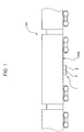
- FIG. 1 is a diagram showing a state where an air compression apparatus for vehicle 1 and air compressor units for vehicle 2 according to one embodiment of the present invention are installed on a vehicle 100 configured as a railway vehicle.
- FIG. 2 is a plan view diagrammatically showing an installation position of the air compression apparatus for vehicle 1 and the air compressor units for vehicle 2 on the vehicle 100.
- the air compression apparatus for vehicle 1 includes a plurality of air compressor units for vehicle 2.
- the air compressor unit for vehicle 2 of this embodiment is also configured as an air compressor unit 2 to be provided in the air compression apparatus 1 for vehicle of this embodiment.
- the air compression apparatus for vehicle 1 is also merely referred to as the "air compression apparatus 1”.
- the air compressor unit for vehicle 2 is also merely referred to as the "air compressor unit 2".
- the air compression apparatus 1 is illustrated to include two air compressor units 2. However, there is no need to have this configuration.
- the air compression apparatus 1 may include three or more air compressor units.
- the air compression apparatus 1 and the air compressor units 2 are installed, for example, below a floor 100a of the vehicle 100 (see FIG. 1 ).
- the air compression apparatus 1 and the air compressor units 2 are mounted on the vehicle 100 to generate compressed air to be used in the vehicle 100.
- the compressed air generated in the air compression apparatus 1 and the air compressor units 2 is used to operate each pneumatic device mounted in the vehicle 100.
- FIG. 2 shows a state of a part of the vehicle 100 viewed from above.
- the air compression apparatus 1 and the air compressor units 2 installed below the floor 100a of the vehicle 100 are shown by chain double-dashed line.
- rails 101 and crossties 102 of a track on which the vehicle 100 travels are also shown by chain double-dashed line in FIG. 2 .
- the air compression apparatus 1 and the air compressor units 2 are installed at a position shifted toward one side from a widthwise center of the vehicle 100 in a width direction of the vehicle 100.
- the width direction of the vehicle 100 is shown by a line A with arrows on both ends.
- the width direction of the vehicle 100 is a direction perpendicular to a traveling direction of the vehicle 100 and parallel to a longitudinal direction of the crossties 102 perpendicular to an extending direction of the rails 101.
- the plurality of (two in this embodiment) air compressor units 2 are installed below the floor 100a of the vehicle 100 while being juxtaposed in the traveling direction of the vehicle 100. Note that the installation mode of the air compression apparatus 1 and the air compressor units 2 shown in FIGS. 1 and 2 is an example.
- FIG. 3 is a perspective view showing the air compression apparatus 1 and the air compressor units 2.
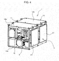
- FIG. 4 is a perspective view of the air compression apparatus 1 with some elements of the air compression apparatus 1 omitted to enable parts of the air compressor unit 2 arranged in the air compression apparatus 1 to be seen.
- FIG. 5 is a diagram showing a system configuration of the air compression apparatus 1 and the air compressor units 2 shown in FIG. 3 .
- the air compression apparatus 1 includes the plurality of (two in this embodiment) air compressor units 2 and a case unit 11.
- the case unit 11 includes a plurality of (two in this embodiment) individual cases 12.
- Each individual case 12 is configured as a housing for holding the air compressor unit 2.
- Each individual case 12 includes a frame body 12a assembled into a rectangular parallelepiped and a plurality of panel bodies 12b attached to the frame body 12a. The plurality of panel bodies 12b are so attached to the frame body 12a as to surround the air compressor unit 2. Note that, in FIG. 4 , the air compression apparatus 1 is shown in a state where one panel body 12b is omitted in one of the plurality of individual cases 12.
- the plurality of individual cases 12 each for holding the air compressor unit 2 are integrally fixed and installed on the vehicle 100 while being juxtaposed in a line.
- the case unit 11 is configured to be installable on the vehicle 100 while holding the plurality of air compressor units 2 juxtaposed in a line.
- FIG. 6 is a perspective view showing one of the two air compressor units shown in FIG. 4 .
- FIG. 7 is a perspective view showing the air compressor unit 2 shown in FIG. 6 when viewed in a direction different from that in FIG. 6 . Note that, in the perspective view of FIG. 7 , the air compressor unit 2 is shown with the individual case 12, which is an element arranged around the air compressor unit 2, omitted.
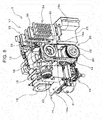
- FIG. 8 is a perspective view showing the air compressor unit 2 shown in FIG. 7 when viewed in a direction different from that in FIG. 7 with some elements omitted to enable an internal structure to be seen.
- each of the plurality of (two in this embodiment) air compressor units 2 includes an air compressor 13, an electric motor 14, air compressor cooling fans 15, a base unit 16, an after-cooler 17, an after-cooler cooling fan 18, a dehumidifier 19, a drive force transmission unit 20, a filter unit 21, a controller 22 and the like.
- the two air compressor units 2 are identically configured. Accordingly, one of the two air compressor units 2 is described below and repeated description on the other air compressor unit 2 is omitted.
- the air compressor 13 for compressing sucked air is configured as a scroll type air compressor including a swing scroll and a fixed scroll. Further, the air compressor 13 is configured as an oil-free type air compressor for compressing air without using oil.
- a suction port as an inlet through which air is sucked in the air compressor 13 is connected to an air suction unit 23 via a suction pipe 24.
- the suction port communicates with outside through the suction pipe 24 and the suction unit 23. Outside air is sucked into the air compressor 13 via the air suction unit 23 and the suction pipe 24.
- the air suction unit 23 is provided with a dust filter for suppressing the passage of dust such as sand dust when the sucked air passes.
- the air compressor 13 is driven by a drive force from the electric motor 14. At this time, the swing scroll rotates while swinging relative to the fixed scroll. In this way, the air is compressed between the swing scroll and the fixed scroll.
- a discharge port as an outlet for discharging the compressed air in the air compressor 13 is connected to the after-cooler 17 via a discharge pipe 25. That is, the discharge port communicates with the after-cooler 17.
- the compressed air generated in the air compressor 13 is supplied to the after-cooler 17 via the discharge pipe 25.
- the discharge pipe 25 may be configured by a pipe formed of an elastic body such as Teflon (registered trademark) or by a copper pipe or a steel pipe. Note that, in this embodiment, not a pipe formed of an elastic body such as Teflon, but a steel pipe is used as the discharge pipe 25 connecting the air compressor 13 and the after-cooler 17.
- an air compressor unit 2 including the air compressor 13 that is the scroll type air compressor is illustrated in this embodiment, a configuration different from this may be adopted.
- An air compressor unit including a screw type air compressor may be configured.
- an air compressor unit may be configured which includes a reciprocating type air compressor to be driven by a reciprocating drive force transmitted thereto while being translated from a rotational drive force from the electric motor 14 via a crank shaft.
- an air compressor unit may be configured which includes an oil type air compressor for compressing air using oil.
- the filter unit 21 is provided as a filter element through which air sucked into the air suction unit 23 and the air compressor cooling fans 15 to be described later passes. Foreign substances are removed when outside air passes through the filter unit 21. As shown in FIGS. 3 and 4 , the filter unit 21 is attached to the individual case 12.
- the filter unit 21 is configured, for example, by a metal plate with a plurality of holes. Alternatively, the filter unit 21 may be configured by a metal net.
- the filter unit 21 is attached to the individual case 12 in such a posture that a surface-like flat wide part of a metal plate or a metal net faces the air suction unit 23 and the air compressor cooling fans 15. Note that a state where the filter unit 21 is removed from the individual case 12 is shown in FIG. 6 .
- the electric motor 14 shown in FIGS. 5 to 8 is provided as a drive source for driving the air compressor 13.
- the electric motor 14 drives the air compressor 13 via the drive force transmission unit 20 to be described later. Specifically, a drive force generated by the electric motor 14 is transmitted to the air compressor 13 via the drive force transmission unit 20. In this way, the swing scroll of the air compressor 13 is rotationally driven while being swung.
- the controller 22 shown in FIGS. 6 to 8 is configured as a control device for controlling the drive of the electric motor 14 by supplying a current from a power supply (not shown) to the electric motor 14.
- the current supplied to the electric motor 14 and a number of revolutions (rotation speed) of the electric motor 14 are controlled by the controller 12.
- a plurality of the air compressor cooling fans 15 is provided.
- two air compressor cooling fans 15 are provided.
- Each of the two air compressor cooling fans 15 is configured as an axial fan including a propeller which rotates about an axis.
- the two air compressor cooling fans 15 are driven by another electric motor provided separately from the electric motor 14.
- the two air compressor cooling fans 15 are arranged side by side in a line in the axial direction. Specifically, the respective air compressor cooling fans 15 are so arranged that axes of rotation are aligned on the same straight line.
- air compressor unit 2 is illustrated to include two air compressor cooling fans 15 in this embodiment, a configuration different from this may be adopted.
- An air compressor unit may be configured which includes only one air compressor cooling fan 15. Further, an air compressor unit may be configured which includes three or more air compressor cooling fans 15.
- the base unit 16 shown in FIGS. 6 to 8 is provided as a member to which the air compressor 13, the electric motor 14 and the like are mounted and fixed and configured, for example, by a steel-made member.
- the base unit 16 is configured as a plate unit in the form of a flat plate.
- the base unit 16 is configured by a flat and wide member and has a first surface 16a and a second surface 16b constituting opposite surfaces thereof. Specifically, the first and second surfaces 16a, 16b are configured as flat surfaces substantially parallel to each other.
- the air compressor 13 is mounted and fixed to the first surface 16a of the base unit 16.
- the electric motor 14 is mounted and fixed to the second surface 16b of the base unit 16.
- the air compressor 13 and the electric motor 14 are arranged side by side along a vertical direction while vertically sandwiching the base unit 16.
- the air compressor unit 2 is installed on the vehicle 100 to have such an arrangement. If this state is viewed from above, at least a part of the electric motor 14 overlaps with the air compressor 13. Further, the air compressor 13 and the electric motor 14 in each of the plurality of air compressor units 2 are arranged side by side along the vertical direction while sandwiching the base unit 16. The case unit 11 and the plurality of air compressor units 2 are installed on the vehicle 100 to have such an arrangement. As just described, in the air compressor unit 2, the air compressor 13 and the electric motor 14 are arranged side by side along the vertical direction.
- the air compressor 13 and the electric motor 14 are separately arranged above and below the base unit 16.
- the air compressor cooling fans 15 provided laterally to the air compressor 13 to cool the air compressor 13 are arranged on the first surface 16a similarly to the air compressor 13.
- the air compressor cooling fans 15 and the electric motor 14 are also separately arranged above and below the base unit 16.
- the air compressor 13 and the air compressor cooling fans 15 are thermally separated from the electric motor 14 by the base unit 16.
- the controller 22 is arranged laterally to the electric motor 14.
- the controller 22 is arranged at a side opposite to the side of the first surface 16a where the air compressor 13 is arranged (side of the second surface 16b where the electric motor 14 is arranged) with respect to the base unit 16.
- the controller 22 is arranged on the side of the second surface 16b with respect to the base unit 16 in a state not fixed to the second surface 16b of the base unit 16.
- a configuration different from this may be adopted.
- the controller 22 may be arranged on the side of the second surface 16b with respect to the base unit 16 in a state fixed to the second surface 16b of the base unit 16.
- the air compressor 13 and the air compressor cooling fans 15 are arranged above the base unit 16 and the electric motor 14 and the controller 20 are arranged below the base unit 16 in a state where the air compressor unit 2 is installed on the vehicle 100.
- a configuration different from this may be adopted.
- the air compressor 13 and the air compressor cooling fans 15 may be arranged below the base unit 16 and the electric motor 14 and the controller 20 may be arranged above the base unit 16 in the state where the air compressor unit 2 is installed on the vehicle 100.
- the after-cooler cooling fan 18 shown in FIGS. 5 , 7 and 8 is configured as a blower to be driven by a drive force of the electric motor 14.
- the after-cooler cooling fan 18 is configured as a centrifugal blower. More specifically, the cooling fan 18 is configured as a sirocco fan.
- the after-cooler cooling fan 18 generates cooling air flow for the after-cooler 17 to be described later and cools the after-cooler 17 from outside. Note that, as described above, the flowing direction of the cooling air for the after-cooler 17 is shown by broken-line arrows in FIG. 5 .
- the after-cooler cooling fan 18 is adjacent to the air compressor 13 in a direction perpendicular to an axial direction of the air compressor cooling fans 15.
- a rotary shaft 26 of the after-cooler cooling fan 18 and a rotary shaft 27 of the air compressor 13 are coaxially provided (see FIG. 5 ).
- the rotary shafts 26, 27 are arranged side by side in a line and provided to integrally rotate.
- an air suction side of the after-cooler cooling fan 18 is provided near the rotary shaft 27 of the air compressor 13.
- the air compressor 13 is provided adjacent to the air suction side of the after-cooler cooling fan 18.
- a blowout port of the after-cooler cooling fan 18 is a direction parallel to a blowout direction of the air compressor cooling fans 15.
- the drive force transmission unit 20 shown in FIGS. 5 and 8 is provided as a mechanism for transmitting a drive force generated by the electric motor 14 to the after-cooler cooling fan 18 and the air compressor 13 and driving the after-cooler cooling fan 18 and the air compressor 13.
- the drive force transmission unit 20 includes a drive pulley 29, a driven pulley 30 and a drive belt 31.
- the drive pulley 29 is configured to integrally rotate with a rotary shaft 32 of the electric motor 14.
- the driven pulley 30 is coupled to the rotary shaft 26 of the after-cooler cooling fan 18.
- the drive belt 31 is wound on the drive pulley 29 and the driven pulley 30 to rotate and configured as an endless belt for transmitting the drive force of the electric motor 14 to the after-cooler cooling fan 18 and the air compressor 13.
- the drive pulley 29 rotates together with the rotary shaft 32.
- the drive belt 31 rotates to rotate the driven pulley 30.
- the rotary shaft 26 of the after-cooler cooling fan 18 rotates together with the driven pulley 30, whereby the after-cooler cooling fan 18 operates.
- the rotary shaft 26 of the after-cooler cooling fan 18 and the rotary shaft 27 of the air compressor 13 are coupled.
- the rotary shaft 27 of the air compressor 13 also rotates together with the rotary shaft 26 of the after-cooler cooling fan 18.
- the air compressor 13 operates together with the after-cooler cooling fan 18.
- the after-cooler 17 shown in FIGS. 5 to 8 is provided as a mechanism for cooling the compressed air generated in the air compressor 13. As described above, the after-cooler 17 is connected to the air compressor 13 via the discharge pipe 25. The after-cooler 17 cools the compressed air generated in the air compressor 13 and supplied via the discharge pipe 25. As shown in FIGS. 6 to 8 , the after-cooler 17 is fixed and mounted on the first surface 16a with respect to the base unit 16.
- the after-cooler 17 includes a first cooler unit 33 and a second cooler unit 34.
- the first cooling unit 33 includes a first flow passage 35.
- the compressed air generated in the air compressor 13 flows in the first flow passage 35. This compressed air is cooled by the cooling air flow generated by the air compressor cooling fans 15.
- the first cooling unit 33 (after-cooler 17) is arranged at a side opposite to the air compressor cooling fans 15 with respect to the air compressor 13. Specifically, the first cooling unit 33 (after-cooler 17) is arranged on an extension line of the rotary shaft of the cooling fans 15.
- the first cooling unit 33 is arranged downstream of the air compressor 13 in a flowing direction of the cooling air generated by the air compressor cooling fans 15 and blown toward the air compressor 13.
- the cooling air generated by the air compressor cooling fans 15 and having cooled the air compressor 13 cools the first flow passage 35 of the first cooling unit 33 from outside. Then, the compressed air flowing in the first flow passage 35 is cooled by the cooled first flow passage 35.
- a duct 37 is disposed around an area downstream of the air compressor 13 in the flowing direction of the cooling air generated by the air compressor cooling fans 15 and having cooled the air compressor 13 (see FIG. 5 ). The duct 37 is provided to guide the cooling air generated by the air compressor cooling fans 15 and having cooled the air compressor 13 to the first cooling unit 33.
- the second cooling unit 34 is connected to the first cooling unit 33.
- the second cooling unit 34 includes a second flow passage 36 into which the compressed air cooled by the first cooling unit 33 after being compressed by the air compressor 13 flows.
- the second flow passage 36 is connected to a downstream side of the first flow passage 33.
- the second cooling unit 34 is cooled by the cooling air flow generated by the after-cooler cooling fan 18. Specifically, the cooling air generated by the after-cooler cooling fan 18 cools the second flow passage 36 of the second cooling unit 34 from outside. Then, the compressed air flowing in the second flow passage 36 is cooled by the cooled second flow passage 36. Thus, the compressed air generated by the air compressor 13 is first cooled in the first cooling unit 33 and then in the second cooling unit 34.
- first cooling unit 33 is arranged laterally to the air compressor 13 and the second cooling unit 34 is arranged laterally to the after-cooler cooling fan 18.
- first and second cooling units 33, 34 are arranged side by side along a horizontal direction in the state where the air compressor unit 2 is installed on the vehicle 100.
- first and second cooling units 33, 34 are arranged side by side along the horizontal direction in each of the plurality of air compressor units 2 in the state where the case unit 11 and the plurality of air compressor units 2 are installed on the vehicle 100.
- FIG. 9 is a view of the after-cooler 17 of the air compressor unit 2 shown in FIGS. 6 to 8 diagrammatically showing a flow passage configuration for the compressed air in the after-cooler 17.
- the first flow passage 35 includes a plurality of first horizontal flow passages 38 extending along the horizontal direction in the state where the air compressor unit 2 is installed on the vehicle 100.
- the first flow passage 35 is configured to meander along the horizontal direction by connecting the plurality of first horizontal flow passages 38 via U-shaped portions.
- the second flow passage 36 includes a plurality of second horizontal flow passages 39 extending along the horizontal direction in the state where the air compressor unit 2 is installed on the vehicle 100.
- the second flow passage 36 is configured to meander along the horizontal direction by connecting the plurality of second horizontal flow passages 39 via U-shaped portions.
- the horizontal direction in the state where the air compressor unit 2 is installed on the vehicle 100 is shown by a line B with arrows on both ends in FIG. 9 .
- a vertical direction in the state where the air compressor unit 2 is installed on the vehicle 100 is shown by a line C with arrows on both ends in FIG. 9 .
- a flowing direction of the compressed air flowing into the first flow passage 35 is shown by an arrow D and that of the compressed air flowing out of the second flow passage 36 is shown by an arrow E in FIG. 9 .
- the plurality of first horizontal flow passages 38 are successively connected via bent flow passages.
- the plurality of second horizontal flow passages 39 are successively connected via bent flow passages.
- the plurality of first horizontal flow passages 38 are arranged in a row or in a plurality of rows along the vertical direction in the state where the air compressor unit 2 is installed on the vehicle 100.
- the plurality of second horizontal flow passages 39 are arranged in a row or in a plurality of rows along the vertical direction in the state where the air compressor unit 2 is installed on the vehicle 100.
- the plurality of first horizontal flow passages 38 are arranged in a plurality of rows along the vertical direction in the state where the air compressor unit 2 is installed on the vehicle 100. Specifically, there are a plurality of rows of the first horizontal flow passages 38 arranged side by side along the vertical direction and the plurality of rows are arranged side by side in the horizontal direction. In the first flow passage 35, the compressed air is cooled successively in the first horizontal flow passages 38 in each row.
- the plurality of second horizontal flow passages 39 are arranged in a plurality of rows along the vertical direction in the state where the air compressor unit 2 is installed on the vehicle 100. Specifically, there are a plurality of rows of the second horizontal flow passages 39 arranged side by side along the vertical direction and the plurality of rows are arranged side by side in the horizontal direction. In the second flow passage 36, the compressed air is cooled successively in the second horizontal flow passages 39 in each row.
- a state where the plurality of first horizontal flow passages 38 are arranged side by side in the vertical direction in one row is shown to facilitate the description of the state where the plurality of first horizontal flow passages 38 are arranged side by side along the vertical direction.
- a state where the plurality of second horizontal flow passages 39 are arranged side by side in the vertical direction in one row is shown to facilitate the description of the state where the plurality of second horizontal flow passages 39 are arranged side by side along the vertical direction.
- the dehumidifier 19 shown in FIGS. 5 to 8 is provided as a mechanism for dehumidifying the compressed air generated by the air compressor 13 and cooled by the after-cooler 17.
- the dehumidifier 19 is connected to a downstream side of the second cooling unit 34 and configured such that the compressed air cooled in the second cooling unit 34 flows thereinto. Further, the dehumidifier 19 is also connected to a compressed air feeding unit 40 for feeding the compressed air generated in the air compressor unit 2 to outside. Note that the compressed air fed from the compressed air feeding unit 40 is supplied to an accumulator (not shown) installed outside the case unit 11 to store the compressed air.
- the compressed air cooled in the second cooling unit 34 and having flowed into the dehumidifier 19 is first dehumidified in the dehumidifier 19. Subsequently, the compressed air dehumidified in the dehumidifier 19 is fed from the compressed air feeding unit 40 and supplied to the accumulator.
- the air compression apparatus 1 By operating each of the plurality of air compressor units 2, the air compression apparatus 1 operates. Note that flows of air during the operations of the air compression apparatus 1 and the air compressor units 2 are shown by solid-line arrows in the diagram of FIG. 5 .
- air as outside air is sucked into the air suction unit 23 by a negative pressure generated by the operation of the air compressor 13.
- the air compressor 13 operates by the operation of the electric motor 14 operated by the control of the controller 22. Further, the air compressor 13 is cooled by the cooling air flow generated by the air compressor cooling fans 15.
- the air sucked into the air suction unit 23 flows into the air compressor 13 and compressed in the air compressor 13.
- the air (compressed air) compressed in the air compressor 13 flows into the after-cooler 17 and cooled in the after-cooler 17.
- the compressed air first passes in the first flow passage 35 of the first cooling unit 33 cooled from outside by the cooling air generated by the air compressor cooling fans 15 and having cooled the air compressor 13. In this way, the compressed air is cooled in the first flow passage 35.
- the compressed air cooled in the first cooling unit 35 passes in the second flow passage 36 of the second cooling unit 34 cooled from outside by the cooling air generated by the after-cooler cooling fan 18. In this way, the compressed air is cooled in the second flow passage 36.
- the compressed air cooled in the after-cooler 17 flows into the dehumidifier 19 and dehumidified in the dehumidifier 19.
- the compressed air dehumidified in the dehumidifier 19 is fed from the compressed air feeding unit 40 and supplied to the accumulator.
- the air compressor unit for vehicle 2 is so mounted and installed on the vehicle 100 that the air compressor 13 and the electric motor 14 are arranged along the vertical direction. This efficiently suppresses the extension and expansion of an installation area necessary in mounting and installing the air compressor unit for vehicle 2 on the vehicle 100. In this way, an increase of the installation area of the air compressor unit for vehicle 2 on the vehicle 100 is suppressed. Further, an increase of the installation area in installing a plurality of air compressor units for vehicle 2 on the vehicle 100 is also suppressed.
- the air compressor unit for vehicle 2 capable of suppressing an increase of the installation area on the vehicle 100. Since an increase of the installation area on the vehicle 100 is suppressed according to this embodiment, a degree of freedom in rigging the air compressor unit for vehicle 2 on the vehicle 100 can be improved.
- the after-cooler cooling fan 18 for generating the cooling air for the after-cooler 17 for cooling the compressed air generated in the air compressor 13 is driven by the drive force of the electric motor 14.
- the after-cooler cooling fan 18 can be driven by efficiently utilizing power of the electric motor 14.
- the structure of the air compressor unit for vehicle 2 as a whole can be compacted and the installation area can be drastically reduced.
- the air suction port of the after-cooler cooling fan 18 is facing toward the air compressor 13.
- the after-cooler cooling fan 18 generates the flow of air around the air compressor 13 adjacent to the air suction side of the after-cooler cooling fan 18 in sucking surrounding air.
- the air compressor 13 is cooled.
- a configuration for cooling the air compressor 13 can be realized by a compact structure. Then, the structure of the air compressor unit for vehicle 2 as a whole can be compacted and the installation area can be drastically reduced.
- the rotary shaft 26 of the after-cooler cooling fan 18 and the rotary shaft 27 of the air compressor 13 are coaxially provided.
- a power transmission mechanism such as a gear is not necessary. Therefore, the structure of the air compressor unit for vehicle 2 as a whole can be compacted and the installation area can be drastically reduced.
- the after-cooler cooling fan 18 is configured as a centrifugal blower capable of easily generating a large air flow.
- the after-cooler 17 can be efficiently cooled by the after-cooler cooling fan 18 as the centrifugal blower.
- the compressed air generated in the air compressor 13 can be efficiently cooled.
- the air compressor 13 can be efficiently cooled by the air compressor cooling fans 15 and the after-cooler 17 can be efficiently cooled by the after-cooler cooling fan 18.
- the compressed air generated in the air compressor 13 can be efficiently cooled.
- the compressed air could be cooled to about 40°C by the air compressor unit for vehicle 2 when the temperature of the compressed air discharged from the air compressor 13 was about 250°C.
- the rotary shafts (26, 27) of the after-cooler cooling fan 18 as the centrifugal blower and the air compressor 13 are coaxially provided.
- the after-cooler 17 can be arranged laterally to, above or below the after-cooler cooling fan 18 and the air compressor 13.
- the after-cooler 17 is arranged laterally to the after-cooler cooling fan 18 and the air compressor 13.
- a duct for guiding the cooling air from the after-cooler cooling fan 18 to the after-cooler 17 can be shortened in length. In this way, the structure of the air compressor unit for vehicle 2 as a whole can be compacted and the installation area can be drastically reduced.
- the rotary shaft 26 of the after-cooler cooling fan 18 configured as the centrifugal blower and the rotary shaft 27 of the air compressor 13 are coaxially provided.
- air near the rotary shaft 27 of the air compressor 13 warmed by heat generated by the air compressor 13 is easily sucked into the after-cooler cooling fan 18.
- devices such as a bearing mounted on the rotary shaft 27 of the air compressor 13 are heated by the heat generated by the air compressor 13.
- the scroll type air compressor including the swing scroll and the fixed scroll is used as the air compressor 13.
- the after-cooler cooling fan 18 that is the centrifugal blower can be arranged at a swing scroll side of the fixed scroll.
- cooling air from the centrifugal blower needs to be guided to the air compressor 13 via a bent duct.
- a pressure loss may be created and cooling efficiency may be reduced.
- the air compressor cooling fans 15 are configured as the axial fans provided laterally to the air compressor 13, the bent duct is not necessary. As a result, the air compressor 13 can be efficiently cooled. Further, if the air compressor cooling fans 15 are axial fans, they are driven by the electric motor provided separately from the electric motor 14 for driving the air compressor 13. Thus, even if the operation of the air compressor 13 is stopped, the air compressor 13 can be cooled by the air compressor cooling fans 15.
- the compressed air generated in the air compressor 13 and having a relatively high temperature is cooled in the first cooling unit 33.
- the first cooling unit 33 is cooled by the cooling air coming from the air compressor cooling fans 15 that are the axial fans, having cooled the air compressor 13 and having a relatively high temperature.
- the compressed air cooled in the first cooling unit 33 is cooled in the second cooling unit 34.
- the second cooling unit 34 is cooled by the cooling air having a low temperature from the after-cooler cooling fan 18 that is the centrifugal blower.
- the first cooling unit 33 is arranged laterally to the air compressor 13 and the second cooling unit 34 is arranged laterally to the after-cooler cooling fan 18.
- the air compressor 13, the after-cooler cooling fan 18 and the after-cooler 17 can be arranged in a compact manner.
- the cooling air from the axial fans for cooling the air compressor 13 can be used to cool the after-cooler 17.
- cooling performance of the after-cooler cooling fan 18 can be set low, wherefore the miniaturization of the after-cooler cooling fan 18 can also be realized.
- the flow passage configuration of the after-cooler 17 is such that cooling by the cooling air from the air compressor cooling fans 15 and cooling by the cooling air from the after-cooler cooling fan 18 are alternately repeated, a state may occur where the compressed air temporarily cooled is warmed and cooled again. In this case, cooling efficiency in cooling the compressed air may be reduced.
- the compressed air can be efficiently cooled since there is no possibility of causing such a reduction in cooling efficiency.
- the air compressor 13 and the electric motor 14 are arranged one above the other and the controller 22 for the electric motor 14 is arranged laterally to the electric motor 14.
- the controller 22 can be arranged at a distance from the air compressor 13 and it can be suppressed that the heat generated from the air compressor 13 affects the controller 22.
- the electric motor 14 and the controller 22 can be arranged proximate to each other.
- a structure can be compacted by proximately arranging the electric motor 14 and the controller 22 while the air compressor 13 and the controller 22 are thermally separated.
- the after-cooler 17 that does not generate vibration is also mounted on the base unit 16 together with the air compressor 13 and the electric motor 14 serving as vibration generation sources.
- the air compressor 13, the electric motor 14, the after-cooler 17 and the base unit 16 are integrally fixed.
- the air compressor 13, the electric motor 14, the after-cooler 17 and the base unit 16 are integrated into a structure.
- the air compressor 13, the electric motor 14, the after-cooler 17 and the base unit 16 have substantially the same natural frequency and substantially the same vibration mode. In this way, not a pipe configured by an elastic body such as Teflon, but a steel pipe available at low cost can be used as the pipe for the flow of the compressed air connecting the air compressor 13 and the after-cooler 17.
- a steel pipe can be used as the discharge pipe 25.
- the after-cooler 17 is mounted on the first surface 16a of the base unit 16 similarly to the air compressor 13.
- the air compressor 13 and the after-cooler 17 can be easily connected by the short discharge pipe 25.
- a pipe structure can be simplified and reduced in cost in the air compressor unit for vehicle 2.
- the steel pipe can be used as the discharge pipe 25 connecting the air compressor 13 and the after-cooler 17, the discharge pipe 25 can be used semipermanently or over a very long time. Therefore, the maintenance of the air compressor unit for vehicle 2 is facilitated.
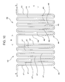
- FIG. 10 is a view of an after-cooler 41 of an air compressor unit for vehicle according to a modification diagrammatically showing a flow passage configuration for compressed air in the after-cooler 41. Note that, in the following description on the modification shown in FIG. 10 , elements configured as in the above embodiment in the air compressor unit for vehicle according to the modification are denoted by the same reference signs as in the above embodiment and not described.
- the after-cooler 41 shown in FIG. 10 is provided as a mechanism for cooling compressed air generated in an air compressor 13.
- the after-cooler 41 is connected to the air compressor 13 via a discharge pipe 25.
- the after-cooler 41 cools the compressed air generated in the air compressor 13 and supplied via the discharge pipe 25.
- the after-cooler 41 is mounted on a base unit 16 by being fixed to a first surface 16a of the base unit 16.
- the after-cooler 41 includes a first cooling unit 42 and a second cooling unit 43.
- the first cooling unit 42 includes a first flow passage 44 in which the compressed air generated in the air compressor 13 flows.
- the first flow passage 44 is cooled by cooling air flow generated by air compressor cooling fans 15.
- the first cooling unit 42 is arranged downstream of the air compressor 13 in a flowing direction of the cooling air generated by the air compressor cooling fans 15 and blown toward the air compressor 13.
- the cooling air generated by the air compressor cooling fans 15 and having cooled the air compressor 13 cools the first flow passage 44 of the first cooling unit 42 from outside. Then, the compressed air flowing in the cooled first flow passage 44 is cooled by the first flow passage 44.
- the second cooling unit 43 is connected to the first cooling unit 42.
- the second cooling unit 43 includes a second flow passage 45 into which the compressed air compressed by the air compressor 13 and cooled by the first cooling unit 42 flows.
- the second flow passage 45 is connected to a downstream side of the first flow passage 44.
- the second cooling unit 43 is cooled by the cooling air generated by an after-cooler cooling fan 18. Specifically, the cooling air generated by the after-cooler cooling fan 18 cools the second flow passage 45 of the second cooling unit 43 from outside. Then, the compressed air flowing in the cooled second flow passage 45 is cooled by the second flow passage 45. Thus, the compressed air generated in the air compressor 13 is first cooled in the first cooling unit 42 and then in the second cooling unit 43.
- first cooling unit 42 is arranged laterally to the air compressor 13 and the second cooling unit 43 is arranged laterally to the after-cooler cooling fan 18.
- first and second cooling units 42, 43 are arranged side by side along a horizontal direction in a state where the air compressor unit according to this modification is installed on the vehicle 100.
- first and second cooling units 42, 43 are arranged side by side along the horizontal direction in each of a plurality of air compressor units 2 in a state where a case unit 11 and the plurality of air compressor units 2 are installed on the vehicle 100.
- the horizontal direction in the state where the air compressor unit according to this modification is installed on the vehicle 100 is shown by a line B with arrows on both ends in FIG. 10 .
- the vertical direction in the state where the air compressor unit according to this modification is installed on the vehicle 100 is shown by a line C with arrows on both ends in FIG. 10 .
- a flowing direction of the compressed air flowing into the first flow passage 44 is shown by an arrow D and that of the compressed air flowing out of the second flow passage 45 is shown by an arrow E in FIG. 10 .
- the plurality of first vertical flow passages 46 are successively connected via bent flow passages.
- the plurality of second vertical flow passages 47 are successively connected via bent flow passages.
- the plurality of first vertical flow passages 46 are arranged in a row or in a plurality of rows along the horizontal direction in the state where the air compressor unit according to this modification is installed on the vehicle 100.
- the plurality of second vertical flow passages 47 are arranged in a row or in a plurality of rows along the horizontal direction in the state where the air compressor unit according to this modification is installed on the vehicle 100.
- the first flow passage 44 that is a flow passage for the compressed air in the first cooling unit 42 is provided to meander along the vertical direction.
- the second flow passage 45 that is a flow passage for the compressed air in the second cooling unit 43 is provided to meander along the vertical direction.
- the air compressor unit 4 operates on operating conditions to provide a smaller amount of heat generation in the air compressor 13.
- the after-cooler cooling fan 18 as provided in the air compressor unit 2 is not provided.
- a driven pulley 30 is fixed to a rotary shaft 27 of the air compressor 13.
- the rotary shaft 27 of the air compressor 13 rotates together with the driven pulley 30.
- a drive force of an electric motor 14 is transmitted to the air compressor 13 via a drive pulley 29, a drive belt 31 and the driven pulley 30.
- the after-cooler 48 is provided as a mechanism for cooling compressed air generated in the air compressor 13.
- the after-cooler 48 is connected to a discharge pipe 25 of the air compressor 13 and a dehumidifier 19.
- the after-cooler 48 cools the compressed air generated in the air compressor 13 and supplied via the discharge pipe 25.
- the after-cooler 48 is arranged downstream of the air compressor 13 in a flowing direction of cooling air generated by air compressor cooling fans 15 and provided adjacent to the air compressor 13 laterally to the air compressor 13. For example, as illustrated in FIG. 11 , the after-cooler 48 is arranged to face a duct 37 in which the cooling air generated by the air compressor cooling fans 15 and having cooled the air compressor 13 flows.
- the after-cooler 48 can be provided adjacent to the air compressor 13 while the influence of the heated air is suppressed to a minimum level. Therefore, the structure of the air compressor unit for vehicle 4 as a whole can be compacted and an installation area can be drastically reduced. Further, since the after-cooler cooling fan 18 as in the above embodiment is not necessary according to the above modification, the structure of the air compressor unit for vehicle 4 as a whole can be compacted and the installation area can be drastically reduced. Note that the number of components can be reduced and low noise and noise reduction can be realized by actively omitting the after-cooler cooling fan 18 as used in the above embodiment when the amount of heat generation in the air compressor 13 is small as in this modification.
- the air compressor unit for vehicle is so installed on the vehicle that the air compressor and the electric motor are arranged along the vertical direction.
- an installation area necessary in installing the air compressor unit for vehicle on the vehicle becomes long and wide.
- an increase of the installation area of the air compressor unit for vehicle on the vehicle is suppressed.
- an increase of an installation area in installing a plurality of air compressor units for vehicle on the vehicle is also suppressed.
- an air compressor unit for vehicle capable of suppressing an increase of an installation area on a vehicle. Since the increase of the installation area on the vehicle is suppressed according to the above configuration, a degree of freedom in rigging the air compressor unit for vehicle on the vehicle can be improved.
- a configuration for arranging the air compressor and the electric motor one above the other is not limited to the one for arranging the air compressor and the electric motor along one vertically extending straight line.
- a configuration for arranging the air compressor and the electric motor along the vertical direction with the air compressor and the electric motor shifted from each other with respect to one vertically extending straight line, i.e. with the air compressor and the electric motor offset is also included.
- the after-cooler cooling fan for generating the cooling air flow for the after-cooler is driven by the drive force of the electric motor.
- the structure of the air compressor unit for vehicle as a whole can be compacted and the installation area can be drastically reduced.
- the after-cooler cooling fan generates an air flow around the air compressor in sucking surrounding air.
- the air compressor is cooled.
- a configuration for cooling the air compressor can be realized by a compact structure. Then, the structure of the air compressor unit for vehicle as a whole can be compacted and the installation area can be drastically reduced.
- the after-cooler cooling fan is configured as the centrifugal blower capable of easily generating a large air flow.
- the after-cooler can be efficiently cooled by the after-cooler cooling fan as the centrifugal blower.
- the compressed air generated in the air compressor can be efficiently cooled.
- the after-cooler can be arranged laterally to, above or below the after-cooler cooling fan and the air compressor.
- a duct for guiding the cooling air from the after-cooler cooling fan to the after-cooler can be shortened in length. In this way, the structure of the air compressor unit for vehicle as a whole can be compacted and the installation area can be drastically reduced.
- Air heated by heat generated in the air compressor moves upward.
- the after-cooler By providing the after-cooler laterally to the air compressor, the after-cooler can be provided adjacent to the air compressor while the influence of the heated air is suppressed to a minimum level. Therefore, the structure of the air compressor unit for vehicle as a whole can be compacted and the installation area can be drastically reduced.
- the compressed air generated in the air compressor and having a relatively high temperature is cooled in the first cooling unit.
- the first cooling unit is cooled by the cooling air coming from the air compressor cooling fan, which is the axial fan, and having a relatively high temperature after having cooled the air compressor.
- the compressed air cooled in the first cooling unit is further cooled in the second cooling unit.
- the second cooling unit is cooled by the cooling air having a lower temperature than that from the after-cooler cooling fan that is the centrifugal blower.
- the first cooling unit is arranged laterally to the air compressor and the second cooling unit is arranged laterally to the after-cooler cooling fan.
- the air compressor, the after-cooler cooling fan and the after-cooler can be arranged in a compact manner.
- the cooling air from the axial fan for cooling the air compressor can be used to cool the after-cooler.
- the miniaturization of the after-cooler cooling fan can also be realized by setting cooling performance of the after-cooler cooling fan low.
- a flow passage configuration of the after-cooler is such that cooling by the cooling air flow from the air compressor cooling fan and cooling by the cooling air from the after-cooler cooling fan are alternately repeated, a state may occur where the compressed air temporarily cooled is warmed and cooled again. In this case, cooling efficiency in cooling the compressed air may be reduced.
- the compressed air can be efficiently cooled since there is no possibility of causing such a reduction in cooling efficiency.
- the first flow passage that is a flow passage for the compressed air in the first cooling unit is provided to meander along the horizontal direction.
- the second flow passage that is a flow passage for the compressed air in the second cooling unit is also provided to meander along the horizontal direction.
- the first flow passage that is a flow passage for the compressed air in the first cooling unit is provided to meander along the vertical direction.
- the second flow passage that is a flow passage for the compressed air in the second cooling unit is also provided to meander along the vertical direction.
- the air compressor and the electric motor are arranged along the vertical direction and the controller for the electric motor is arranged laterally to the electric motor.
- the controller can be arranged at a distance from the air compressor and it can be suppressed that the controller is affected by heat generated in the air compressor.
- the electric motor and the controller can be proximately arranged. Therefore, the structure can be compacted by proximately arranging the electric motor and the controller while the air compressor and the controller are thermally separated.
- an air compressor unit for vehicle capable of suppressing an increase of an installation area on a vehicle.
- the present invention can be widely applied to air compressor units for vehicle to be mounted on vehicles.
Landscapes
- Engineering & Computer Science (AREA)
- Mechanical Engineering (AREA)
- General Engineering & Computer Science (AREA)
- Compressor (AREA)
- Compressors, Vaccum Pumps And Other Relevant Systems (AREA)
Applications Claiming Priority (1)
| Application Number | Priority Date | Filing Date | Title |
|---|---|---|---|
| JP2014101848A JP6325336B2 (ja) | 2014-05-15 | 2014-05-15 | 車両用空気圧縮機ユニット |
Publications (2)
| Publication Number | Publication Date |
|---|---|
| EP2949863A1 true EP2949863A1 (de) | 2015-12-02 |
| EP2949863B1 EP2949863B1 (de) | 2019-09-04 |
Family
ID=53051729
Family Applications (1)
| Application Number | Title | Priority Date | Filing Date |
|---|---|---|---|
| EP15166868.8A Active EP2949863B1 (de) | 2014-05-15 | 2015-05-08 | Luftverdichtereinheit für ein fahrzeug |
Country Status (5)
| Country | Link |
|---|---|
| US (1) | US10137909B2 (de) |
| EP (1) | EP2949863B1 (de) |
| JP (1) | JP6325336B2 (de) |
| KR (2) | KR20150131991A (de) |
| CN (2) | CN106884795B (de) |
Families Citing this family (11)
| Publication number | Priority date | Publication date | Assignee | Title |
|---|---|---|---|---|
| JP2016014381A (ja) * | 2014-07-03 | 2016-01-28 | ナブテスコ株式会社 | 車両用空気圧縮装置 |
| CN105351192B (zh) * | 2015-11-25 | 2017-09-29 | 中车唐山机车车辆有限公司 | 磁浮车用风源装置 |
| CN105526164A (zh) * | 2016-01-26 | 2016-04-27 | 东莞市康驰实业有限公司 | 一种车载直流直联式无油涡旋空气压缩机 |
| US10704552B2 (en) * | 2016-02-02 | 2020-07-07 | Powerex/Iwata Air Technology Inc. | Vacuum system |
| CN107956693A (zh) * | 2016-10-14 | 2018-04-24 | 泉州市华德机电设备有限公司 | 永磁无油涡旋空气压缩机 |
| US11959492B2 (en) * | 2018-11-05 | 2024-04-16 | Powerex-Iwata Air Technology, Inc. | Hybrid after cooling system and method of operation |
| JP7658711B2 (ja) * | 2019-02-12 | 2025-04-08 | ナブテスコ株式会社 | 空気圧縮装置 |
| CN110821789A (zh) * | 2019-12-13 | 2020-02-21 | 南京恒达压缩机有限公司 | 空气压缩机的冷却系统及冷却方法 |
| JP2021143596A (ja) * | 2020-03-10 | 2021-09-24 | ナブテスコ株式会社 | 圧縮装置及び車両用圧縮装置ユニット |
| JP2024503798A (ja) * | 2020-12-21 | 2024-01-29 | サルエアー エルエルシー | ガス圧縮機用クーラーマウント配置 |
| WO2025223652A1 (en) * | 2024-04-24 | 2025-10-30 | Zf Cv Systems Global Gmbh | Compressor unit, housing for a compressor unit and vehicle |
Citations (14)
| Publication number | Priority date | Publication date | Assignee | Title |
|---|---|---|---|---|
| JPS59165951A (ja) * | 1983-03-08 | 1984-09-19 | Aisin Seiki Co Ltd | リニアモ−タ−カ−のためのスタ−リングサイクル冷凍機用の冷却装置 |
| EP0587157A2 (de) * | 1992-09-11 | 1994-03-16 | Hitachi, Ltd. | Schraubenverdichteranlage angeordnet in einem kompakten Gehäuse |
| WO2004101998A1 (de) * | 2003-05-19 | 2004-11-25 | Ilmvac Gmbh | Scrollpumpe |
| JP2004332557A (ja) * | 2003-04-30 | 2004-11-25 | Tokico Ltd | スクロール式流体機械 |
| EP1500819A2 (de) * | 2003-06-06 | 2005-01-26 | Kabushiki Kaisha Toyota Jidoshokki | Rootsverdichteraggregat |
| JP2005076481A (ja) * | 2003-08-29 | 2005-03-24 | Mitsubishi Electric Corp | 車両用空気圧縮装置 |
| US20050169788A1 (en) * | 2003-12-26 | 2005-08-04 | Yuji Komai | Scroll type fluid machinery |
| JP2005207414A (ja) * | 2003-12-26 | 2005-08-04 | Hitachi Ltd | スクロール式流体機械 |
| EP1967735A1 (de) * | 2005-12-27 | 2008-09-10 | Sekisui Chemical Co., Ltd. | Einstufige roots-vakuumpumpe und die einstufige roots-vakuumpumpe einsetzendes vakuumfluidtransportsystem |
| DE202008013732U1 (de) * | 2008-10-08 | 2009-02-12 | Relo Gmbh | Wassereingespritzte Schraubenkompressoranlage |
| JP3150077U (ja) | 2009-01-29 | 2009-04-30 | 三菱重工業株式会社 | 鉄道車両用空気圧縮装置 |
| JP2011153534A (ja) * | 2010-01-26 | 2011-08-11 | Nabtesco Corp | 鉄道車両用空気圧縮装置 |
| JP2011169220A (ja) * | 2010-02-18 | 2011-09-01 | Nabtesco Corp | 鉄道車両用空気圧縮装置 |
| WO2012085833A1 (en) * | 2010-12-22 | 2012-06-28 | Koninklijke Philips Electronics N.V. | Nebulizer device |
Family Cites Families (36)
| Publication number | Priority date | Publication date | Assignee | Title |
|---|---|---|---|---|
| US2921732A (en) * | 1956-04-16 | 1960-01-19 | Vin Henry E De | Control for compressors |
| CA1279856C (en) * | 1985-10-09 | 1991-02-05 | Akira Suzuki | Oilless rotary type compressor system |
| US4929161A (en) * | 1987-10-28 | 1990-05-29 | Hitachi, Ltd. | Air-cooled oil-free rotary-type compressor |
| JP2716934B2 (ja) * | 1994-04-08 | 1998-02-18 | 株式会社神戸製鋼所 | パッケージ形油冷式空気圧縮機 |
| US5417554A (en) * | 1994-07-19 | 1995-05-23 | Ingersoll-Rand Company | Air cooling system for scroll compressors |
| JP3423514B2 (ja) * | 1995-11-30 | 2003-07-07 | アネスト岩田株式会社 | スクロール流体機械 |
| JPH1030594A (ja) | 1996-07-15 | 1998-02-03 | Kobe Steel Ltd | 空冷パッケージ形圧縮機 |
| US6027311A (en) * | 1997-10-07 | 2000-02-22 | General Electric Company | Orifice controlled bypass system for a high pressure air compressor system |
| US6247314B1 (en) | 1998-01-30 | 2001-06-19 | Ingersoll-Rand Company | Apparatus and method for continuously disposing of condensate in a fluid compressor system |
| JP3488825B2 (ja) * | 1998-03-19 | 2004-01-19 | 株式会社日立産機システム | パッケージ型スクロール圧縮機 |
| JP4026099B2 (ja) * | 1998-10-15 | 2007-12-26 | アネスト岩田株式会社 | スクロール流体機械 |
| US6357242B1 (en) | 2000-07-20 | 2002-03-19 | Delphi Technologies, Inc. | Control system and method for suppressing head pressure spikes in a vehicle air conditioning system |
| JP2002155879A (ja) * | 2000-11-22 | 2002-05-31 | Hitachi Ltd | オイルフリースクリュー圧縮機 |
| JP4208620B2 (ja) * | 2003-03-27 | 2009-01-14 | 三洋電機株式会社 | 冷媒サイクル装置 |
| JP4673136B2 (ja) * | 2005-06-09 | 2011-04-20 | 株式会社日立産機システム | スクリュー圧縮機 |
| DE102005033084B4 (de) * | 2005-07-15 | 2007-10-11 | Knorr-Bremse Systeme für Schienenfahrzeuge GmbH | Öleingespritzter Verdichter mit Mitteln zur Öltemperaturregelung |
| JP4629546B2 (ja) * | 2005-09-30 | 2011-02-09 | アネスト岩田株式会社 | スクロール流体機械 |
| JP2007270665A (ja) * | 2006-03-30 | 2007-10-18 | Hitachi Ltd | パッケージ型圧縮機 |
| JP4938436B2 (ja) * | 2006-12-15 | 2012-05-23 | カルソニックカンセイ株式会社 | 車両用冷却ファン制御システム |
| JP4325668B2 (ja) | 2006-12-25 | 2009-09-02 | トヨタ自動車株式会社 | 車両用空調装置 |
| JP4885077B2 (ja) | 2007-07-03 | 2012-02-29 | 株式会社日立産機システム | 無給油式スクリュー圧縮機 |
| US8821131B2 (en) | 2008-02-05 | 2014-09-02 | Hitachi Koki Co., Ltd. | Air compressor |
| JP5210777B2 (ja) | 2008-09-25 | 2013-06-12 | 株式会社日立産機システム | パッケージ型圧縮機 |
| JP4864063B2 (ja) * | 2008-10-27 | 2012-01-25 | 株式会社日立産機システム | 圧縮機ユニット |
| US8177534B2 (en) * | 2008-10-30 | 2012-05-15 | Advanced Scroll Technologies (Hangzhou), Inc. | Scroll-type fluid displacement apparatus with improved cooling system |
| US8128379B2 (en) * | 2008-11-19 | 2012-03-06 | Wabtec Holding Corp. | Temperature management system for a 2CD type air compressor |
| JP5452908B2 (ja) * | 2008-11-28 | 2014-03-26 | 株式会社日立産機システム | 無給油式スクリュー圧縮機 |
| JP5286108B2 (ja) * | 2009-03-02 | 2013-09-11 | 株式会社日立産機システム | スクロール式流体機械 |
| JP2011080366A (ja) | 2009-10-02 | 2011-04-21 | Anest Iwata Corp | モータ直結型圧縮機ユニット |
| JP5769332B2 (ja) | 2010-06-02 | 2015-08-26 | アネスト岩田株式会社 | スクロール膨張機 |
| JP5606181B2 (ja) | 2010-06-30 | 2014-10-15 | 株式会社日立産機システム | 圧縮機 |
| EP2644895A4 (de) * | 2010-11-22 | 2018-01-31 | UD Trucks Corporation | Druckluftzufuhrvorrichtung |
| JP5779463B2 (ja) | 2011-09-26 | 2015-09-16 | 株式会社日立産機システム | パッケージ型圧縮機 |
| JP5774455B2 (ja) * | 2011-11-30 | 2015-09-09 | 株式会社日立産機システム | 無給油式圧縮機 |
| JP5998028B2 (ja) * | 2012-11-30 | 2016-09-28 | 株式会社日立産機システム | スクロール式流体機械 |
| JP5899150B2 (ja) * | 2013-04-19 | 2016-04-06 | 株式会社日立産機システム | パッケージ型流体機械 |
-
2014
- 2014-05-15 JP JP2014101848A patent/JP6325336B2/ja active Active
-
2015
- 2015-05-05 US US14/704,370 patent/US10137909B2/en active Active
- 2015-05-08 EP EP15166868.8A patent/EP2949863B1/de active Active
- 2015-05-12 KR KR1020150066093A patent/KR20150131991A/ko not_active Ceased
- 2015-05-14 CN CN201710182612.0A patent/CN106884795B/zh active Active
- 2015-05-14 CN CN201510246747.XA patent/CN105089973B/zh active Active
-
2017
- 2017-05-04 KR KR1020170057015A patent/KR101777089B1/ko active Active
Patent Citations (14)
| Publication number | Priority date | Publication date | Assignee | Title |
|---|---|---|---|---|
| JPS59165951A (ja) * | 1983-03-08 | 1984-09-19 | Aisin Seiki Co Ltd | リニアモ−タ−カ−のためのスタ−リングサイクル冷凍機用の冷却装置 |
| EP0587157A2 (de) * | 1992-09-11 | 1994-03-16 | Hitachi, Ltd. | Schraubenverdichteranlage angeordnet in einem kompakten Gehäuse |
| JP2004332557A (ja) * | 2003-04-30 | 2004-11-25 | Tokico Ltd | スクロール式流体機械 |
| WO2004101998A1 (de) * | 2003-05-19 | 2004-11-25 | Ilmvac Gmbh | Scrollpumpe |
| EP1500819A2 (de) * | 2003-06-06 | 2005-01-26 | Kabushiki Kaisha Toyota Jidoshokki | Rootsverdichteraggregat |
| JP2005076481A (ja) * | 2003-08-29 | 2005-03-24 | Mitsubishi Electric Corp | 車両用空気圧縮装置 |
| US20050169788A1 (en) * | 2003-12-26 | 2005-08-04 | Yuji Komai | Scroll type fluid machinery |
| JP2005207414A (ja) * | 2003-12-26 | 2005-08-04 | Hitachi Ltd | スクロール式流体機械 |
| EP1967735A1 (de) * | 2005-12-27 | 2008-09-10 | Sekisui Chemical Co., Ltd. | Einstufige roots-vakuumpumpe und die einstufige roots-vakuumpumpe einsetzendes vakuumfluidtransportsystem |
| DE202008013732U1 (de) * | 2008-10-08 | 2009-02-12 | Relo Gmbh | Wassereingespritzte Schraubenkompressoranlage |
| JP3150077U (ja) | 2009-01-29 | 2009-04-30 | 三菱重工業株式会社 | 鉄道車両用空気圧縮装置 |
| JP2011153534A (ja) * | 2010-01-26 | 2011-08-11 | Nabtesco Corp | 鉄道車両用空気圧縮装置 |
| JP2011169220A (ja) * | 2010-02-18 | 2011-09-01 | Nabtesco Corp | 鉄道車両用空気圧縮装置 |
| WO2012085833A1 (en) * | 2010-12-22 | 2012-06-28 | Koninklijke Philips Electronics N.V. | Nebulizer device |
Also Published As
| Publication number | Publication date |
|---|---|
| KR101777089B1 (ko) | 2017-09-08 |
| US10137909B2 (en) | 2018-11-27 |
| CN105089973B (zh) | 2017-08-18 |
| KR20150131991A (ko) | 2015-11-25 |
| EP2949863B1 (de) | 2019-09-04 |
| CN106884795B (zh) | 2019-01-25 |
| CN106884795A (zh) | 2017-06-23 |
| US20150329125A1 (en) | 2015-11-19 |
| CN105089973A (zh) | 2015-11-25 |
| JP6325336B2 (ja) | 2018-05-16 |
| JP2015218639A (ja) | 2015-12-07 |
| KR20170055022A (ko) | 2017-05-18 |
Similar Documents
| Publication | Publication Date | Title |
|---|---|---|
| EP2949863B1 (de) | Luftverdichtereinheit für ein fahrzeug | |
| KR101765441B1 (ko) | 공기 압축 장치 | |
| US11473582B2 (en) | Package-type compressor | |
| KR101729847B1 (ko) | 공기 압축 장치 | |
| CN104110364B (zh) | 箱式流体机械 | |
| JP5314456B2 (ja) | 空冷式スクロール圧縮機 | |
| US20060061222A1 (en) | Air bearing and motor cooling | |
| JP2012020728A (ja) | キャビン空気コンプレッサ装置およびその冷却方法 | |
| US8674565B2 (en) | System and method for increasing airflow in electric machines | |
| JP6678302B2 (ja) | 温度調和ユニット、温度調和システム、車両 | |
| US10704552B2 (en) | Vacuum system | |
| CN103370516B (zh) | 封装体收纳型发动机式作业机械 | |
| RU2463697C2 (ru) | Вентилятор | |
| KR20100037693A (ko) | 터보 블로워의 외함 | |
| EP1431679A2 (de) | Lüftungskasten | |
| EP3696421A1 (de) | Luftkompressionsvorrichtung | |
| KR20110036676A (ko) | 모터 직결형 압축기 유닛 |
Legal Events
| Date | Code | Title | Description |
|---|---|---|---|
| AK | Designated contracting states |
Kind code of ref document: A1 Designated state(s): AL AT BE BG CH CY CZ DE DK EE ES FI FR GB GR HR HU IE IS IT LI LT LU LV MC MK MT NL NO PL PT RO RS SE SI SK SM TR |
|
| AX | Request for extension of the european patent |
Extension state: BA ME |
|
| PUAI | Public reference made under article 153(3) epc to a published international application that has entered the european phase |
Free format text: ORIGINAL CODE: 0009012 |
|
| 17P | Request for examination filed |
Effective date: 20160530 |
|
| RBV | Designated contracting states (corrected) |
Designated state(s): AL AT BE BG CH CY CZ DE DK EE ES FI FR GB GR HR HU IE IS IT LI LT LU LV MC MK MT NL NO PL PT RO RS SE SI SK SM TR |
|
| STAA | Information on the status of an ep patent application or granted ep patent |
Free format text: STATUS: EXAMINATION IS IN PROGRESS |
|
| 17Q | First examination report despatched |
Effective date: 20171025 |
|
| GRAP | Despatch of communication of intention to grant a patent |
Free format text: ORIGINAL CODE: EPIDOSNIGR1 |
|
| STAA | Information on the status of an ep patent application or granted ep patent |
Free format text: STATUS: GRANT OF PATENT IS INTENDED |
|
| INTG | Intention to grant announced |
Effective date: 20190522 |
|
| GRAS | Grant fee paid |
Free format text: ORIGINAL CODE: EPIDOSNIGR3 |
|
| GRAA | (expected) grant |
Free format text: ORIGINAL CODE: 0009210 |
|
| STAA | Information on the status of an ep patent application or granted ep patent |
Free format text: STATUS: THE PATENT HAS BEEN GRANTED |
|
| AK | Designated contracting states |
Kind code of ref document: B1 Designated state(s): AL AT BE BG CH CY CZ DE DK EE ES FI FR GB GR HR HU IE IS IT LI LT LU LV MC MK MT NL NO PL PT RO RS SE SI SK SM TR |
|
| REG | Reference to a national code |
Ref country code: GB Ref legal event code: FG4D |
|
| REG | Reference to a national code |
Ref country code: CH Ref legal event code: EP |
|
| REG | Reference to a national code |
Ref country code: AT Ref legal event code: REF Ref document number: 1175611 Country of ref document: AT Kind code of ref document: T Effective date: 20190915 |
|
| REG | Reference to a national code |
Ref country code: DE Ref legal event code: R096 Ref document number: 602015037028 Country of ref document: DE |
|
| REG | Reference to a national code |
Ref country code: IE Ref legal event code: FG4D |
|
| REG | Reference to a national code |
Ref country code: NL Ref legal event code: MP Effective date: 20190904 |
|
| REG | Reference to a national code |
Ref country code: LT Ref legal event code: MG4D |
|
| PG25 | Lapsed in a contracting state [announced via postgrant information from national office to epo] |
Ref country code: BG Free format text: LAPSE BECAUSE OF FAILURE TO SUBMIT A TRANSLATION OF THE DESCRIPTION OR TO PAY THE FEE WITHIN THE PRESCRIBED TIME-LIMIT Effective date: 20191204 Ref country code: HR Free format text: LAPSE BECAUSE OF FAILURE TO SUBMIT A TRANSLATION OF THE DESCRIPTION OR TO PAY THE FEE WITHIN THE PRESCRIBED TIME-LIMIT Effective date: 20190904 Ref country code: LT Free format text: LAPSE BECAUSE OF FAILURE TO SUBMIT A TRANSLATION OF THE DESCRIPTION OR TO PAY THE FEE WITHIN THE PRESCRIBED TIME-LIMIT Effective date: 20190904 Ref country code: NO Free format text: LAPSE BECAUSE OF FAILURE TO SUBMIT A TRANSLATION OF THE DESCRIPTION OR TO PAY THE FEE WITHIN THE PRESCRIBED TIME-LIMIT Effective date: 20191204 Ref country code: FI Free format text: LAPSE BECAUSE OF FAILURE TO SUBMIT A TRANSLATION OF THE DESCRIPTION OR TO PAY THE FEE WITHIN THE PRESCRIBED TIME-LIMIT Effective date: 20190904 Ref country code: SE Free format text: LAPSE BECAUSE OF FAILURE TO SUBMIT A TRANSLATION OF THE DESCRIPTION OR TO PAY THE FEE WITHIN THE PRESCRIBED TIME-LIMIT Effective date: 20190904 |
|
| PG25 | Lapsed in a contracting state [announced via postgrant information from national office to epo] |
Ref country code: RS Free format text: LAPSE BECAUSE OF FAILURE TO SUBMIT A TRANSLATION OF THE DESCRIPTION OR TO PAY THE FEE WITHIN THE PRESCRIBED TIME-LIMIT Effective date: 20190904 Ref country code: LV Free format text: LAPSE BECAUSE OF FAILURE TO SUBMIT A TRANSLATION OF THE DESCRIPTION OR TO PAY THE FEE WITHIN THE PRESCRIBED TIME-LIMIT Effective date: 20190904 Ref country code: GR Free format text: LAPSE BECAUSE OF FAILURE TO SUBMIT A TRANSLATION OF THE DESCRIPTION OR TO PAY THE FEE WITHIN THE PRESCRIBED TIME-LIMIT Effective date: 20191205 Ref country code: ES Free format text: LAPSE BECAUSE OF FAILURE TO SUBMIT A TRANSLATION OF THE DESCRIPTION OR TO PAY THE FEE WITHIN THE PRESCRIBED TIME-LIMIT Effective date: 20190904 Ref country code: AL Free format text: LAPSE BECAUSE OF FAILURE TO SUBMIT A TRANSLATION OF THE DESCRIPTION OR TO PAY THE FEE WITHIN THE PRESCRIBED TIME-LIMIT Effective date: 20190904 |
|
| REG | Reference to a national code |
Ref country code: AT Ref legal event code: MK05 Ref document number: 1175611 Country of ref document: AT Kind code of ref document: T Effective date: 20190904 |
|
| PG25 | Lapsed in a contracting state [announced via postgrant information from national office to epo] |
Ref country code: RO Free format text: LAPSE BECAUSE OF FAILURE TO SUBMIT A TRANSLATION OF THE DESCRIPTION OR TO PAY THE FEE WITHIN THE PRESCRIBED TIME-LIMIT Effective date: 20190904 Ref country code: EE Free format text: LAPSE BECAUSE OF FAILURE TO SUBMIT A TRANSLATION OF THE DESCRIPTION OR TO PAY THE FEE WITHIN THE PRESCRIBED TIME-LIMIT Effective date: 20190904 Ref country code: AT Free format text: LAPSE BECAUSE OF FAILURE TO SUBMIT A TRANSLATION OF THE DESCRIPTION OR TO PAY THE FEE WITHIN THE PRESCRIBED TIME-LIMIT Effective date: 20190904 Ref country code: NL Free format text: LAPSE BECAUSE OF FAILURE TO SUBMIT A TRANSLATION OF THE DESCRIPTION OR TO PAY THE FEE WITHIN THE PRESCRIBED TIME-LIMIT Effective date: 20190904 Ref country code: PL Free format text: LAPSE BECAUSE OF FAILURE TO SUBMIT A TRANSLATION OF THE DESCRIPTION OR TO PAY THE FEE WITHIN THE PRESCRIBED TIME-LIMIT Effective date: 20190904 Ref country code: PT Free format text: LAPSE BECAUSE OF FAILURE TO SUBMIT A TRANSLATION OF THE DESCRIPTION OR TO PAY THE FEE WITHIN THE PRESCRIBED TIME-LIMIT Effective date: 20200106 |
|
| PG25 | Lapsed in a contracting state [announced via postgrant information from national office to epo] |
Ref country code: CZ Free format text: LAPSE BECAUSE OF FAILURE TO SUBMIT A TRANSLATION OF THE DESCRIPTION OR TO PAY THE FEE WITHIN THE PRESCRIBED TIME-LIMIT Effective date: 20190904 Ref country code: SK Free format text: LAPSE BECAUSE OF FAILURE TO SUBMIT A TRANSLATION OF THE DESCRIPTION OR TO PAY THE FEE WITHIN THE PRESCRIBED TIME-LIMIT Effective date: 20190904 Ref country code: IS Free format text: LAPSE BECAUSE OF FAILURE TO SUBMIT A TRANSLATION OF THE DESCRIPTION OR TO PAY THE FEE WITHIN THE PRESCRIBED TIME-LIMIT Effective date: 20200224 Ref country code: SM Free format text: LAPSE BECAUSE OF FAILURE TO SUBMIT A TRANSLATION OF THE DESCRIPTION OR TO PAY THE FEE WITHIN THE PRESCRIBED TIME-LIMIT Effective date: 20190904 |
|
| REG | Reference to a national code |
Ref country code: DE Ref legal event code: R097 Ref document number: 602015037028 Country of ref document: DE |
|
| PLBE | No opposition filed within time limit |
Free format text: ORIGINAL CODE: 0009261 |
|
| STAA | Information on the status of an ep patent application or granted ep patent |
Free format text: STATUS: NO OPPOSITION FILED WITHIN TIME LIMIT |
|
| PG2D | Information on lapse in contracting state deleted |
Ref country code: IS |
|
| PG25 | Lapsed in a contracting state [announced via postgrant information from national office to epo] |
Ref country code: DK Free format text: LAPSE BECAUSE OF FAILURE TO SUBMIT A TRANSLATION OF THE DESCRIPTION OR TO PAY THE FEE WITHIN THE PRESCRIBED TIME-LIMIT Effective date: 20190904 Ref country code: IS Free format text: LAPSE BECAUSE OF FAILURE TO SUBMIT A TRANSLATION OF THE DESCRIPTION OR TO PAY THE FEE WITHIN THE PRESCRIBED TIME-LIMIT Effective date: 20200105 |
|
| 26N | No opposition filed |
Effective date: 20200605 |
|
| PG25 | Lapsed in a contracting state [announced via postgrant information from national office to epo] |
Ref country code: SI Free format text: LAPSE BECAUSE OF FAILURE TO SUBMIT A TRANSLATION OF THE DESCRIPTION OR TO PAY THE FEE WITHIN THE PRESCRIBED TIME-LIMIT Effective date: 20190904 |
|
| PG25 | Lapsed in a contracting state [announced via postgrant information from national office to epo] |
Ref country code: CH Free format text: LAPSE BECAUSE OF NON-PAYMENT OF DUE FEES Effective date: 20200531 Ref country code: LI Free format text: LAPSE BECAUSE OF NON-PAYMENT OF DUE FEES Effective date: 20200531 Ref country code: MC Free format text: LAPSE BECAUSE OF FAILURE TO SUBMIT A TRANSLATION OF THE DESCRIPTION OR TO PAY THE FEE WITHIN THE PRESCRIBED TIME-LIMIT Effective date: 20190904 |
|
| REG | Reference to a national code |
Ref country code: BE Ref legal event code: MM Effective date: 20200531 |
|
| PG25 | Lapsed in a contracting state [announced via postgrant information from national office to epo] |
Ref country code: LU Free format text: LAPSE BECAUSE OF NON-PAYMENT OF DUE FEES Effective date: 20200508 |
|
| PG25 | Lapsed in a contracting state [announced via postgrant information from national office to epo] |
Ref country code: IE Free format text: LAPSE BECAUSE OF NON-PAYMENT OF DUE FEES Effective date: 20200508 |
|
| PG25 | Lapsed in a contracting state [announced via postgrant information from national office to epo] |
Ref country code: BE Free format text: LAPSE BECAUSE OF NON-PAYMENT OF DUE FEES Effective date: 20200531 |
|
| PG25 | Lapsed in a contracting state [announced via postgrant information from national office to epo] |
Ref country code: TR Free format text: LAPSE BECAUSE OF FAILURE TO SUBMIT A TRANSLATION OF THE DESCRIPTION OR TO PAY THE FEE WITHIN THE PRESCRIBED TIME-LIMIT Effective date: 20190904 Ref country code: MT Free format text: LAPSE BECAUSE OF FAILURE TO SUBMIT A TRANSLATION OF THE DESCRIPTION OR TO PAY THE FEE WITHIN THE PRESCRIBED TIME-LIMIT Effective date: 20190904 Ref country code: CY Free format text: LAPSE BECAUSE OF FAILURE TO SUBMIT A TRANSLATION OF THE DESCRIPTION OR TO PAY THE FEE WITHIN THE PRESCRIBED TIME-LIMIT Effective date: 20190904 |
|
| PG25 | Lapsed in a contracting state [announced via postgrant information from national office to epo] |
Ref country code: MK Free format text: LAPSE BECAUSE OF FAILURE TO SUBMIT A TRANSLATION OF THE DESCRIPTION OR TO PAY THE FEE WITHIN THE PRESCRIBED TIME-LIMIT Effective date: 20190904 |
|
| P01 | Opt-out of the competence of the unified patent court (upc) registered |
Effective date: 20230523 |
|
| PGFP | Annual fee paid to national office [announced via postgrant information from national office to epo] |
Ref country code: DE Payment date: 20250521 Year of fee payment: 11 |
|
| PGFP | Annual fee paid to national office [announced via postgrant information from national office to epo] |
Ref country code: GB Payment date: 20250527 Year of fee payment: 11 |
|
| PGFP | Annual fee paid to national office [announced via postgrant information from national office to epo] |
Ref country code: IT Payment date: 20250527 Year of fee payment: 11 |
|
| PGFP | Annual fee paid to national office [announced via postgrant information from national office to epo] |
Ref country code: FR Payment date: 20250528 Year of fee payment: 11 |