EP2949876B1 - System und verfahren zur kontrolle von triebwerkstransienten für schnelle änderungen der triebwerksleistungsanfordung - Google Patents
System und verfahren zur kontrolle von triebwerkstransienten für schnelle änderungen der triebwerksleistungsanfordung Download PDFInfo
- Publication number
- EP2949876B1 EP2949876B1 EP15169329.8A EP15169329A EP2949876B1 EP 2949876 B1 EP2949876 B1 EP 2949876B1 EP 15169329 A EP15169329 A EP 15169329A EP 2949876 B1 EP2949876 B1 EP 2949876B1
- Authority
- EP
- European Patent Office
- Prior art keywords
- engine
- heating element
- gas turbine
- power demand
- engine power
- Prior art date
- Legal status (The legal status is an assumption and is not a legal conclusion. Google has not performed a legal analysis and makes no representation as to the accuracy of the status listed.)
- Not-in-force
Links
Images

Classifications
-
- F—MECHANICAL ENGINEERING; LIGHTING; HEATING; WEAPONS; BLASTING
- F01—MACHINES OR ENGINES IN GENERAL; ENGINE PLANTS IN GENERAL; STEAM ENGINES
- F01D—NON-POSITIVE DISPLACEMENT MACHINES OR ENGINES, e.g. STEAM TURBINES
- F01D25/00—Component parts, details, or accessories, not provided for in, or of interest apart from, other groups
- F01D25/02—De-icing means for engines having icing phenomena
-
- F—MECHANICAL ENGINEERING; LIGHTING; HEATING; WEAPONS; BLASTING
- F01—MACHINES OR ENGINES IN GENERAL; ENGINE PLANTS IN GENERAL; STEAM ENGINES
- F01D—NON-POSITIVE DISPLACEMENT MACHINES OR ENGINES, e.g. STEAM TURBINES
- F01D15/00—Adaptations of machines or engines for special use; Combinations of engines with devices driven thereby
- F01D15/10—Adaptations for driving, or combinations with, electric generators
-
- F—MECHANICAL ENGINEERING; LIGHTING; HEATING; WEAPONS; BLASTING
- F02—COMBUSTION ENGINES; HOT-GAS OR COMBUSTION-PRODUCT ENGINE PLANTS
- F02C—GAS-TURBINE PLANTS; AIR INTAKES FOR JET-PROPULSION PLANTS; CONTROLLING FUEL SUPPLY IN AIR-BREATHING JET-PROPULSION PLANTS
- F02C3/00—Gas-turbine plants characterised by the use of combustion products as the working fluid
- F02C3/04—Gas-turbine plants characterised by the use of combustion products as the working fluid having a turbine driving a compressor
-
- F—MECHANICAL ENGINEERING; LIGHTING; HEATING; WEAPONS; BLASTING
- F02—COMBUSTION ENGINES; HOT-GAS OR COMBUSTION-PRODUCT ENGINE PLANTS
- F02C—GAS-TURBINE PLANTS; AIR INTAKES FOR JET-PROPULSION PLANTS; CONTROLLING FUEL SUPPLY IN AIR-BREATHING JET-PROPULSION PLANTS
- F02C7/00—Features, components parts, details or accessories, not provided for in, or of interest apart form groups F02C1/00 - F02C6/00; Air intakes for jet-propulsion plants
- F02C7/04—Air intakes for gas-turbine plants or jet-propulsion plants
- F02C7/047—Heating to prevent icing
-
- H—ELECTRICITY
- H02—GENERATION; CONVERSION OR DISTRIBUTION OF ELECTRIC POWER
- H02P—CONTROL OR REGULATION OF ELECTRIC MOTORS, ELECTRIC GENERATORS OR DYNAMO-ELECTRIC CONVERTERS; CONTROLLING TRANSFORMERS, REACTORS OR CHOKE COILS
- H02P9/00—Arrangements for controlling electric generators for the purpose of obtaining a desired output
- H02P9/008—Arrangements for controlling electric generators for the purpose of obtaining a desired output wherein the generator is controlled by the requirements of the prime mover
-
- F—MECHANICAL ENGINEERING; LIGHTING; HEATING; WEAPONS; BLASTING
- F05—INDEXING SCHEMES RELATING TO ENGINES OR PUMPS IN VARIOUS SUBCLASSES OF CLASSES F01-F04
- F05D—INDEXING SCHEME FOR ASPECTS RELATING TO NON-POSITIVE-DISPLACEMENT MACHINES OR ENGINES, GAS-TURBINES OR JET-PROPULSION PLANTS
- F05D2220/00—Application
- F05D2220/30—Application in turbines
- F05D2220/32—Application in turbines in gas turbines
-
- F—MECHANICAL ENGINEERING; LIGHTING; HEATING; WEAPONS; BLASTING
- F05—INDEXING SCHEMES RELATING TO ENGINES OR PUMPS IN VARIOUS SUBCLASSES OF CLASSES F01-F04
- F05D—INDEXING SCHEME FOR ASPECTS RELATING TO NON-POSITIVE-DISPLACEMENT MACHINES OR ENGINES, GAS-TURBINES OR JET-PROPULSION PLANTS
- F05D2220/00—Application
- F05D2220/70—Application in combination with
- F05D2220/76—Application in combination with an electrical generator
-
- F—MECHANICAL ENGINEERING; LIGHTING; HEATING; WEAPONS; BLASTING
- F05—INDEXING SCHEMES RELATING TO ENGINES OR PUMPS IN VARIOUS SUBCLASSES OF CLASSES F01-F04
- F05D—INDEXING SCHEME FOR ASPECTS RELATING TO NON-POSITIVE-DISPLACEMENT MACHINES OR ENGINES, GAS-TURBINES OR JET-PROPULSION PLANTS
- F05D2270/00—Control
Definitions
- the present disclosure generally relates to a system and a method for managing engine transients for rapid power demand changes, such as during engine loading and unloading.
- Gas turbine engines may be used to supply power in various types of vehicles and systems, including, but not limited to, aircraft, naval propulsion, and the like.
- a gas turbine engine generally includes a compressor section, a combustor section, and a turbine section.
- the compressor section receives and compresses a flow of intake air.
- the compressed air then enters the combustor section in which a steady stream of fuel is injected, mixed with the compressed air, and ignited, resulting in high energy combustion gas, which is then directed to the turbine section.
- the combustion gas causes turbine blades to rotate and generate energy, from which electrical power may be extracted via an electrical generator coupled mechanically or hydraulically to the gas turbine engine.
- the electrical power may be used by various loads within the vehicle or system, such as control systems, actuators, climate control systems, and the like.
- a heater is powered by generator to selectively add heat to a gas turbine cycle.
- an electrical, hydraulic, or mechanical load may suddenly be removed, thereby reducing engine power demand, such that the gas turbine engine may be generating excess engine power. This in turn may result in rapid and undesirable acceleration of the gas turbine engine.
- the gas turbine engine may require several seconds to achieve this state. At or near idle speeds, the gas turbine engine may be near the compressor surge line, and as such may need to be managed accordingly. This in turn affects the ability for the gas turbine engine to have a quick response.
- An exemplary system for managing engine transients may include a gas turbine engine having at least one compressor section configured to receive an inlet air stream, and at least one turbine section mounted on at least one spool.
- the gas turbine engine may be configured to operate at an engine power level to satisfy an engine power demand.
- the exemplary system may also include at least one generator operatively coupled to the gas turbine engine.
- the at least one generator may be configured to generate electrical power based at least in part on the engine power demand.
- the system further may include at least one heating element in communication with the at least one generator, and at least one control unit coupled to the at least one heating element.
- the at least one heating element may be configured to receive electrical power from the at least one generator to generate thermal energy.
- the at least one control unit may be configured to energize the at least one heating element if a first condition and/or a second condition exists.
- the first condition may include the engine power demand dropping below the engine power level, and the second condition may include an anticipated increase in the engine power demand.
- the at least one heating element may be located upstream of the at least one compressor section, such as in an inlet duct of the gas turbine engine, such that the thermal energy may be transferred to the inlet air stream.
- An exemplary method of managing the engine transients may include first commanding the gas turbine engine and the generator to operate at an optimum speed for a current power setpoint. The method then may include determining if the first condition and/or the second condition exists. If so, the method then may include energizing the at least one heating element to convert at least a portion of the electrical power into thermal energy to exchange heat with an inlet air stream into the gas turbine engine.
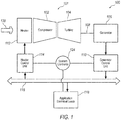
- the system 100 may include a gas turbine engine 101, as depicted in FIG. 2 . While the gas turbine engine 101 is depicted in FIG. 2 as a turbofan, it should be appreciated that it may be, but is not limited to, a turbofan, a turboshaft, or a turboprop.
- the gas turbine engine 101 generally may include a compressor section 102 and a turbine section 104 mounted on a common shaft or spool. As seen in FIG. 2 , the gas turbine engine 101 may be a multi-spool engine having low pressure (LP) and high pressure (HP) compressors and/or turbines.
- LP low pressure
- HP high pressure
- the gas turbine engine 101 may be a single spool engine.
- the compressor section 102 generally may be configured to receive and compress an inlet air stream 120.
- the compressed air may then be mixed with a steady stream of fuel and ignited in a combustor section 103.
- the resulting combustion gas may then enter the turbine section 104 in which the combustion gas causes turbine blades to rotate and generate energy.
- the system 100 may also include a generator 106 coupled to the spool of the gas turbine engine 101 via a shaft 108, and a generator control unit 110 coupled to the generator 106.
- the generator 106 may be coupled to any one of the spools, for example a LP spool such that the generator 106 may be a LP generator.
- the generator 106 generally may be an electrical generator configured to extract energy from the gas turbine engine 101 and generate electrical power. The electrical power may then be used by one or more application electrical loads 118 within the vehicle.
- the application electrical loads 118 may include, but are not limited to, control systems, actuators, climate control systems, and the like.
- the generator control unit 110 may be configured to control the operation of the generator 106, and to communicate with other system components, such as the application electrical loads 118. For example, the generator control unit 110 may command the generator 106 to distribute electrical power to the application electrical loads 118 via a power bus 116.
- the system 100 may further include a heater 112 and a heater control unit 114 coupled to the heater 112.
- the heater 112 generally may be any electrically operated heating element or circuit configured to receive electrical power to generate thermal energy, including, but not limited to, a heater pad.
- the heater 112 generally may have a steady state power limit and a transient power limit. While only one heater 112 is shown, it should be appreciated that there may be any number of heaters 112, where each heater 112 may be coupled to a separate heater control unit 114, or multiple heaters 112 may be coupled to at least one heater control unit 114.
- the heater 112 may be located upstream of the compressor 102 such that it may provide the thermal energy to the inlet air stream 120, i.e., heat the inlet air stream 120.
- the heater 112 may be located in an inlet duct 122 of the gas turbine engine 101. In another exemplary approach in which the gas turbine engine 101 is a turboprop having a propeller (not shown), the heater 112 may be located in or around the propeller. It should be appreciated that the heater 112 may be located anywhere within the gas turbine engine 101 or the vehicle that thermal energy may be required or desirable, not just upstream of the compressor section 102. For example, vehicles often include anti-icing or de-icing systems and/or circuits at various locations where ice buildup is undesirable, such as at the engine inlet, the wings of an aircraft, etc. Such existing systems may be utilized as the heater 112, which would eliminate the need to install additional equipment, thereby saving costs to implement the system 100. Furthermore, the heater 112 may be used in lieu of or in addition to batteries, capacitance banks, flywheels, or the like to store excess electrical energy generated by the generator 106, as described in more detail hereinafter.
- the heater control unit 114 generally may be configured to control the operation of the heater 112.
- the heater control unit 114 may be in communication with the generator control unit 110 and/or the power bus 116 such that electrical power may be supplied from the generator 106 to the heater 112 when required, such as for engine transient conditions. For example, one or more of the application electrical loads 118 may be suddenly removed, thereby reducing the engine power demand from the gas turbine engine 101. However, the gas turbine engine 101 may not adjust its power output quickly enough to counter the load removal, thereby resulting in excess power, i.e., the engine power is greater than the engine power demand. As such, it may be desirable to transfer the excess power to another load, i.e., the heater 112, to prevent the gas turbine engine 101 from rapidly accelerating.
- the heater control unit 114 may energize the heater 112 such that the excess power may be transferred to the inlet air stream 120 via electrical heat to help maintain engine loading and reduce engine speed increases, thereby helping the engine decelerate.
- the energy may be reclaimed by the gas turbine engine 101 for the period during and after the electrical heat is applied. Due to the relatively long time constant (slow response) of the heating system, the reabsorption of heat by the gas turbine engine 101 may occur after the fuel has been reduced and the gas turbine engine 101 is decelerating or is at a low power condition.
- the gas turbine engine 101 may be a multi-spool engine having a LP spool and a HP spool, where the generator 106 is coupled to the LP spool, as mentioned above.
- the heater control unit 114 may energize the heater 112 to increase the electrical power generated by the generator 106 and generator loading on the LP spool, thereby resulting in an increase in HP speed and fueling.
- the heater control unit 114 may turn off the heater 112 in order to reduce the engine power if the power demand exceeds the power available from the gas turbine engine 101.
- the added electrical heat introduced at the engine inlet by the heater 112 may be at least partially recovered by the gas turbine engine 101 to assist the HP speed to accelerate.
- the HP idle speed will increase when the heater 112 is switched on to provide the benefit of higher engine power and higher HP speed with the onset of the higher power demand.
- the heater control unit 114 may energize the heater 112 at a predetermined time frame, for example five seconds, before the engine power demand actually increases. During this time frame, the heater 112 may be allowed to exceed its steady state limits transiently. However, if power demand increase is impending but the exact timing is unknown, the heater 112 may be energized for a longer period of time, where the heater 112 may not exceed its steady state limit.
- the engine can take a much larger fuel rate increase and therefore sustain a faster acceleration without problems.
- the previously generated heat from the inlet may be released during the engine acceleration such that the heat energy is partially re-absorbed into the engine to temporarily boost the inlet energy to assist the acceleration.
- the engine speed driving the generator 106 may be raised to the maximum speed limit for low power operation of the generator 106 and the gas turbine engine 101. This may store additional rotational kinetic energy in the system 100 that may be absorbed as the generator and engine speed droops when the engine power increase occurs.
- Installation of the heater 112 and/or the static structure of the gas turbine engine 101 at the engine inlet may be designed to have significant heat capacity to allow the release of electrical heat to the inlet air stream 120 to occur over an extended period of time after the heater 112 has been switched off, such as when the gas turbine engine 101 is no longer generating excess power.
- multiple heaters 112 may be located at various locations at the engine inlet and staged in operation.
- the gas turbine engine 101 at the inlet for example the inlet duct 122, may be made of a material having a high heat capacity above a predetermined threshold, and/or may be a relatively large structure such that there may be a large available area for heat transfer to the inlet air stream 120 to occur.
- This may help reduce the peak temperature of the heater 112, increase the specific heat capacity to allow larger amounts of heat to be absorbed, and allow a larger heat flow to the inlet air stream 120. In icing conditions, this may allow the heater 112 to be switched off when the application electrical loads 118 are applied to reduce the peak electrical power off take. This may also help to minimize the variation in electrical load and therefore loading of the generator 106 that may occur due to electrical power transients and drop-outs that may occur, as explained above.
- the system 100 may include a system controller 124 in communication with the gas turbine engine 101, the generator control unit 110, the heater control unit 114, and/or the application electrical loads 118.
- the system controller 124 may determine when a condition exists, and direct the generator control unit 110 and/or the heater control unit 114 to control the operation of the generator 106 and the heater 112, respectively.
- the condition may be where the engine power demand drops below the engine power, such as when one of the application electrical loads 118 and/or a mechanical or hydraulic load is removed.
- Another condition may be when an increase in the engine power demand is anticipated or requested, such as when the gas turbine engine 101 accelerates from an idle speed within a predetermined time frame.
- the system of dissipating and storing electrical heat energy and rotational kinetic energy may also be applied to rapidly changing hydraulic or mechanical loads to the system that occur faster than the gas turbine engine 101 may respond. It should further be appreciated that this system may be applied for cases in which the generator 106 is driven by a hydraulic motor powered by an engine driven hydraulic pump.
- Computing devices such as the generator control unit 110 and the heater control unit 114, generally include computer-executable instructions such as the instructions of the system controller 18, where the instructions may be executable by one or more computing devices such as those listed above.
- Computer-executable instructions may be compiled or interpreted from computer programs created using a variety of programming languages and/or technologies, including, without limitation, and either alone or in combination, JavaTM, C, C++, C#, Objective C, Visual Basic, Java Script, Perl, etc.
- a processor e.g., a microprocessor
- receives instructions e.g., from a memory, a computer-readable medium, etc., and executes these instructions, thereby performing one or more processes, including one or more of the processes described herein.
- Such instructions and other data may be stored and transmitted using a variety of computer-readable media.
- a computer-readable medium includes any non-transitory (e.g., tangible) medium that participates in providing data (e.g., instructions) that may be read by a computer (e.g., by a processor of a computer).
- a medium may take many forms, including, but not limited to, non-volatile media and volatile media.
- Non-volatile media may include, for example, optical or magnetic disks and other persistent memory.
- Volatile media may include, for example, dynamic random access memory (DRAM), which typically constitutes a main memory.
- Such instructions may be transmitted by one or more transmission media, including coaxial cables, copper wire and fiber optics, including the wires that comprise a system bus coupled to a processor of a computer.
- Computer-readable media include, for example, a floppy disk, a flexible disk, hard disk, magnetic tape, any other magnetic medium, a CD-ROM, DVD, any other optical medium, punch cards, paper tape, any other physical medium with patterns of holes, a RAM, a PROM, an EPROM, a FLASH-EEPROM, any other memory chip or cartridge, or any other medium from which a computer can read.
- Databases, data repositories or other data stores described herein may include various kinds of mechanisms for storing, accessing, and retrieving various kinds of data, including a hierarchical database, a set of files in a file system, an application database in a proprietary format, a relational database management system (RDBMS), etc.
- Each such data store is generally included within a computing device employing a computer operating system such as one of those mentioned above, and are accessed via a network in any one or more of a variety of manners.
- a file system may be accessible from a computer operating system, and may include files stored in various formats.
- An RDBMS generally employs the Structured Query Language (SQL) in addition to a language for creating, storing, editing, and executing stored procedures, such as the PL/SQL language mentioned above.
- SQL Structured Query Language
- system elements may be implemented as computer-readable instructions (e.g., software) on one or more computing devices (e.g., servers, personal computers, etc.), stored on computer readable media associated therewith (e.g., disks, memories, etc.).
- a computer program product may comprise such instructions stored on computer readable media for carrying out the functions described herein.
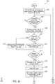
- Method 200 begins at block 202 at which the heater 112 may be switched off if it is on, and the gas turbine engine 101 and the generator 106 may be commanded, for example by the system controller 124, to operate at optimum speed for a current power setpoint.
- method 200 may include determining, if an increased engine power demand is anticipated or requested. If no, then block 204 may proceed to block 222. If yes, then method 200 may proceed to block 206 at which the speed of the generator 106 may be increased to a low power generator/engine speed limit.
- method 200 may then include determining if a transient heater limit is exceeded.
- method 200 may proceed to block 212 at which the heater 112 may be energized to the transient heater power limit. If yes, then method 200 may proceed to block 210 at which the heater 112 may be energized to a steady state power limit. After either block 210 or 212, method 200 may proceed to block 214 at which it may be determined whether there has been an actual engine power demand increase. If no, method 200 may go back to block 204. If yes, then method 200 may proceed to blocks 216 through 220 at which the gas turbine engine 101 may be commanded to rapidly increase in power, the heater 112 may be switched off, and the engine speed may be allowed to droop to optimal speed for high power operation.
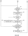
- method 200 may include determining if the engine power demand is below the engine power, for example if any of the application electrical loads 118 have been removed. If no, method 200 may go back to block 202 to repeat method 200 until one of the conditions from blocks 204 and 222 are present. Alternatively, method 200 may end. If yes, method 200 may proceed to block 224 at which the engine 101 may be commanded to rapidly decrease in engine power. At block 226, method 200 may then include determining if a transient heater limit is exceeded. If no, such as when the heater 112 is turned off, method 200 may proceed to block 230 at which the heater 112 may be energized to the transient heater power limit.
- method 200 may proceed to block 228 at which the heater 112 may be energized to a steady state power limit. After either block 228 or 230, method 200 may proceed to block 232 at which it may be determined if the engine power is less than the engine power demand or if the engine speed is decreasing and is below an engine speed transient limit. If either one of these conditions is present, method 200 may proceed to block 234 at which the heater 112 may be switched off. If neither one is present, method 200 may go back to block 222. After block 234, method 200 may go back to block 202 to repeat itself, or alternatively, method 200 may end.
Landscapes
- Engineering & Computer Science (AREA)
- Chemical & Material Sciences (AREA)
- Combustion & Propulsion (AREA)
- Mechanical Engineering (AREA)
- General Engineering & Computer Science (AREA)
- Power Engineering (AREA)
- Engine Equipment That Uses Special Cycles (AREA)
Claims (15)
- System (100), umfassend:ein Gasturbinentriebwerk (101) mit mindestens einem Verdichterabschnitt (102) und mindestens einem Turbinenabschnitt (104), der auf mindestens einer Welle (108) montiert ist, wobei der mindestens eine Verdichterabschnitt (102) dazu ausgestaltet ist, einen Zuluftstrom (120) aufzunehmen, wobei das Gasturbinentriebwerk (101) dazu ausgestaltet ist, auf einem eine Triebwerksleistungsanforderung erfüllenden Triebwerksleistungspegel zu arbeiten;mindestens einen Generator (106), der mit dem Gasturbinentriebwerk (101) in Wirkverbindung steht, wobei der mindestens eine Generator (106) dazu ausgestaltet ist, elektrische Leistung zumindest teilweise auf der Grundlage der Triebwerksleistungsanforderung zu erzeugen;mindestens ein Heizelement (112) in Verbindung mit dem mindestens einen Generator (106), wobei das mindestens eine Heizelement (112) dazu ausgestaltet ist, elektrische Leistung aus dem mindestens einen Generator (106) aufzunehmen, um Wärmeenergie zu erzeugen und Wärme mit dem Zuluftstrom (120) auszutauschen; undmindestens eine Steuereinheit (114), die an das mindestens eine Heizelement (112) gekoppelt ist,dadurch gekennzeichnet, dass die mindestens eine Steuereinheit (114) dazu ausgestaltet ist, bei einem voraussichtlichen Anstieg derTriebwerksleistungsanforderung in einem vorgegebenen Zeitrahmen vor einem tatsächlichen Anstieg der Triebwerksleistungsanforderung das mindestens eine Heizelement (112) unter Strom zu setzen und das mindestens eine Heizelement (112) auszuschalten, wenn ein tatsächlicher Anstieg der Triebwerksleistungsanforderung eintritt.
- System (100) nach Anspruch 1, dadurch gekennzeichnet, dass die mindestens eine Steuereinheit (114) ferner dazu ausgestaltet ist, das mindestens eine Heizelement (112) unter Strom zu setzen, wenn die Triebwerksleistungsanforderung unter den Triebwerksleistungspegel sinkt.
- System (100) nach einem der Ansprüche 1 oder 2, wobei das Gasturbinentriebwerk (101) eines aus einem Wellenleistungstriebwerk, einem Turboprop-Triebwerk und einem Mantelstromtriebwerk ist.
- System (100) nach einem der Ansprüche 1 bis 3, wobei das Gasturbinentriebwerk (101) ein Turboprop-Triebwerk mit einem Propeller ist und das mindestens eine Heizelement (112) sich an dem Propeller befindet.
- System (100) nach einem der Ansprüche 1 bis 4, wobei das mindestens eine Heizelement (112) dem mindestens einen Verdichterabschnitt (102) derart vorgeschaltet ist, dass das mindestens eine Heizelement (112) die Wärmeenergie auf den Zuluftstrom überträgt.
- System (100) nach einem der Ansprüche 1 bis 5, wobei das Gasturbinentriebwerk (101) einen Einlasskanal (122) aufweist, durch den der Zuluftstrom in das Gasturbinentriebwerk (101) gesaugt wird, wobei das mindestens eine Heizelement (112) sich innerhalb des Einlasskanals (122) befindet.
- System (100) nach einem der Ansprüche 1 bis 6, wobei zumindest ein Teil des Einlasskanals (122) aus einem Material hergestellt ist, das eine Wärmekapazität aufweist, die über einem vorgegebenen Schwellenwert liegt.
- System (106) nach einem der Ansprüche 1 bis 7, wobei das mindestens eine Heizelement (112) eine stationäre Leistungsgrenze und eine transiente Leistungsgrenze aufweist und die mindestens eine Steuereinheit (114) dazu ausgestaltet ist, das mindestens eine Heizelement (112) bis an eine stationäre Leistungsgrenze unter Strom zu setzen, wenn die transiente Heizergrenze überschritten wird, und das mindestens eine Heizelement (112) bis an die transiente Leistungsgrenze unter Strom zu setzen, wenn sie nicht überschritten wird.
- System (106) nach einem der Ansprüche 1 bis 8, wobei das mindestens eine Heizelement (112) eine elektrische Heizmatte ist.
- System (106) nach einem der Ansprüche 1 bis 9, wobei das mindestens eine Heizelement (112) ein Enteisungskreis ist.
- System (106) nach einem der Ansprüche 1 bis 10, wobei der elektrische Generator (106) durch eine Hydropumpe, die durch das Gasturbinentriebwerk (101) mechanisch angetrieben wird, hydraulisch angetrieben wird.
- Verfahren (200), umfassend:Betätigen eines Gasturbinentriebwerkes (101) und eines Generators (106), der mit dem Gasturbinentriebwerk (101) in Wirkverbindung steht, derart, dass diese mit einer optimalen Drehzahl für einen aktuellen Leistungssollwert arbeiten, wobei das Gasturbinentriebwerk (101) auf einem eine Triebwerksleistungsanforderung erfüllenden Triebwerksleistungspegel arbeitet und der Generator (106) elektrische Leistung zumindest teilweise auf der Grundlage der Triebwerksleistungsanforderung erzeugt;Bestimmen (124), ob ein voraussichtlicher Anstieg der Triebwerksleistungsanforderung vorliegt;dadurch gekennzeichnet, dass, falls ein voraussichtlicher Anstieg der Triebwerksleistungsanforderung vorliegt, das Verfahren ferner Unterstromsetzen (230) mindestens eines Heizelementes (112) einschließt, um zumindest einen Teil der elektrischen Leistung in Wärmeenergie umzuwandeln, um Wärme mit einem Zuluftstrom (120) in das Gasturbinentriebwerk (101) auszutauschen, in einem vorgegebenen Zeitrahmen vor einem tatsächlichen Anstieg der Triebwerksleistungsanforderung, und um das mindestens eine Heizelement (112) auszuschalten, wenn ein tatsächlicher Anstieg der Triebwerksleistungsanforderung eintritt.
- Verfahren (200) nach Anspruch 12, wobei der voraussichtliche Anstieg der Triebwerksleistungsanforderung eintritt, wenn das Gasturbinentriebwerk (101) innerhalb des vorgegebenen Zeitrahmens von einer Leerlaufdrehzahl aus beschleunigt.
- Verfahren (200) nach einem der Ansprüche 12 bis 13, wobei das Unterstromsetzen (210) des mindestens einen Heizelementes eine transiente Grenze des mindestens einen Heizelementes (112) nicht überschreitet, wenn ein voraussichtlicher Anstieg der Triebwerksleistungsanforderung vorliegt.
- Verfahren (200) nach einem der Ansprüche 12 bis 14, ferner umfassend, falls die Triebwerksleistungsanforderung unter den Triebwerksleistungspegel sinkt, das Ausschalten (234) des mindestens einen Heizelementes (112), wenn entweder die Triebwerksleistung geringer als die Triebwerksleistungsanforderung ist oder die Triebwerksleistungsdrehzahl unter eine Triebwerksdrehzahlgrenze sinkt.
Applications Claiming Priority (1)
| Application Number | Priority Date | Filing Date | Title |
|---|---|---|---|
| US201462004534P | 2014-05-29 | 2014-05-29 |
Publications (2)
| Publication Number | Publication Date |
|---|---|
| EP2949876A1 EP2949876A1 (de) | 2015-12-02 |
| EP2949876B1 true EP2949876B1 (de) | 2020-07-08 |
Family
ID=53267256
Family Applications (1)
| Application Number | Title | Priority Date | Filing Date |
|---|---|---|---|
| EP15169329.8A Not-in-force EP2949876B1 (de) | 2014-05-29 | 2015-05-27 | System und verfahren zur kontrolle von triebwerkstransienten für schnelle änderungen der triebwerksleistungsanfordung |
Country Status (2)
| Country | Link |
|---|---|
| US (1) | US9765640B2 (de) |
| EP (1) | EP2949876B1 (de) |
Families Citing this family (4)
| Publication number | Priority date | Publication date | Assignee | Title |
|---|---|---|---|---|
| US10036321B2 (en) * | 2014-05-29 | 2018-07-31 | General Electric Company | Systems and methods for utilizing gas turbine compartment ventilation discharge air |
| US11035300B2 (en) * | 2019-03-29 | 2021-06-15 | Rolls-Royce Corporation | Control of a gas turbine driving a generator of an electrical system based on faults detected in the electrical system |
| CN111044362B (zh) * | 2019-12-05 | 2021-09-14 | 武汉理工大学 | 瞬态卸荷装置和岩体瞬态卸荷模拟试验系统 |
| US12687132B1 (en) | 2025-03-24 | 2026-07-21 | Pratt & Whitney Canada Corp. | Control system and method for powering a low inertia generator with a gas turbine engine and maintaining speed governing tolerance |
Family Cites Families (20)
| Publication number | Priority date | Publication date | Assignee | Title |
|---|---|---|---|---|
| GB1174969A (en) * | 1967-10-20 | 1969-12-17 | Rolls Royce | Gas Turbine Engine Provided with an Alternator |
| US4773212A (en) * | 1981-04-01 | 1988-09-27 | United Technologies Corporation | Balancing the heat flow between components associated with a gas turbine engine |
| US4696156A (en) * | 1986-06-03 | 1987-09-29 | United Technologies Corporation | Fuel and oil heat management system for a gas turbine engine |
| US4782658A (en) * | 1987-05-07 | 1988-11-08 | Rolls-Royce Plc | Deicing of a geared gas turbine engine |
| US5114100A (en) * | 1989-12-29 | 1992-05-19 | The Boeing Company | Anti-icing system for aircraft |
| GB2243412B (en) * | 1990-03-30 | 1994-11-23 | United Technologies Corp | Aircraft engine propulsor blade deicing |
| US5353370A (en) | 1993-03-11 | 1994-10-04 | Calspan Corporation | Non-uniform temperature profile generator for use in short duration wind tunnels |
| US6725645B1 (en) * | 2002-10-03 | 2004-04-27 | General Electric Company | Turbofan engine internal anti-ice device |
| US7690186B2 (en) * | 2005-11-09 | 2010-04-06 | Pratt & Whitney Canada Corp. | Gas turbine engine including apparatus to transfer power between multiple shafts |
| FR2911848B1 (fr) | 2007-01-31 | 2009-12-25 | Hispano Suiza Sa | Circuit d'alimentation en energie electrique dans un aeronef pour des equipements electriques comprenant un circuit de degivrage |
| US7854582B2 (en) * | 2007-05-08 | 2010-12-21 | Pratt & Whitney Canada Corp. | Operation of an aircraft engine after emergency shutdown |
| FR2935357B1 (fr) | 2008-09-03 | 2010-08-27 | Aircelle Sa | Procede de fabrication d'un element de nacelle |
| US9004407B2 (en) * | 2008-12-24 | 2015-04-14 | Middle River Aircraft Systems | Anti-icing system and method for preventing ice accumulation |
| US20100162720A1 (en) * | 2008-12-31 | 2010-07-01 | Bowman Ray F | Gas turbine engine |
| FR2941439B1 (fr) | 2009-01-28 | 2011-01-14 | Aircelle Sa | Dispositif de degivrage electrique et systeme de controle associe |
| US20100326041A1 (en) * | 2009-06-30 | 2010-12-30 | Wayne Garcia Edmondson | Heated guide vane |
| US20110154805A1 (en) | 2009-12-31 | 2011-06-30 | Craig Heathco | Power augmentation system for an engine powered air vehicle |
| US20130076120A1 (en) * | 2011-02-28 | 2013-03-28 | Hamilton Sundstrand Corporation | Aircraft emergency power system |
| US20130219916A1 (en) | 2012-02-24 | 2013-08-29 | General Electric Company | Apparatus and method for conditioning air received by a power generation system |
| GB201415078D0 (en) * | 2014-08-26 | 2014-10-08 | Rolls Royce Plc | Gas turbine engine anti-icing system |
-
2015
- 2015-05-27 EP EP15169329.8A patent/EP2949876B1/de not_active Not-in-force
- 2015-05-27 US US14/722,339 patent/US9765640B2/en active Active
Non-Patent Citations (1)
| Title |
|---|
| None * |
Also Published As
| Publication number | Publication date |
|---|---|
| US9765640B2 (en) | 2017-09-19 |
| EP2949876A1 (de) | 2015-12-02 |
| US20160160682A1 (en) | 2016-06-09 |
Similar Documents
| Publication | Publication Date | Title |
|---|---|---|
| EP2930335B1 (de) | Kraftstoff-luft-verhältnissteuerung von gasturbinenmotoren | |
| US10583931B2 (en) | System and method for coordinated control of a power system | |
| US9688414B2 (en) | Intelligent integrated control system and method | |
| EP2990626B1 (de) | Betrieb von flugzeugmotoren während transient-bedingungen | |
| JP6609566B2 (ja) | マルチエンジンヘリコプターの待機状態にあるターボシャフトエンジンを支援する方法、および待機状態になることが可能な少なくとも1つのターボシャフトエンジンを備えるヘリコプターの推進システムのアーキテクチャ | |
| KR102318629B1 (ko) | 다발 엔진 헬리콥터 추진 시스템의 구성, 및 대응하는 헬리콥터 | |
| US7854582B2 (en) | Operation of an aircraft engine after emergency shutdown | |
| US9765640B2 (en) | System and method to manage transients for rapid power demand changes | |
| EP3502444B1 (de) | Verfahren und vorrichtung zur steuerung der elektrischen leistung, die einem bauteil eines fahrzeugs zugeführt wird | |
| EP4086446B1 (de) | Hybrider elektrischer leerlauf und bremsung für ein flugzeug | |
| US20160083106A1 (en) | Device for cutting-off power to the alternators of a turbine engine during acceleration | |
| EP2887536B1 (de) | Steuersystem für einen doppelt redundanten Motor/Generator und Motor | |
| US20150308347A1 (en) | Method to control electric starter generator for gas turbine engines | |
| CN112292517B (zh) | 具有热量回收的非对称推进系统 | |
| EP3832096A1 (de) | Elektrisches assistenzsystem für eine turbomaschine eines flugzeugs, verfahren zum betreiben einer turbomaschine eines flugzeugs und flugzeug | |
| US20130291549A1 (en) | Device and a method of regulating a power plant including at least one turbine engine, and an aircraft | |
| CN108150293B (zh) | 用于限制喘振风险的涡轮发动机上的提取的控制方法和装置 | |
| CA2472409C (en) | Aircraft secondary electric load controlling system | |
| US20050229838A1 (en) | Aircraft secondary electric load controlling system | |
| JP7511536B2 (ja) | 航空機の推進システム | |
| CN120523075A (zh) | 用于基于apu能力进行负载管理的方法和系统 | |
| CN117597506A (zh) | 用于控制混合推进系统的能量设置的方法 |
Legal Events
| Date | Code | Title | Description |
|---|---|---|---|
| AK | Designated contracting states |
Kind code of ref document: A1 Designated state(s): AL AT BE BG CH CY CZ DE DK EE ES FI FR GB GR HR HU IE IS IT LI LT LU LV MC MK MT NL NO PL PT RO RS SE SI SK SM TR |
|
| AX | Request for extension of the european patent |
Extension state: BA ME |
|
| PUAI | Public reference made under article 153(3) epc to a published international application that has entered the european phase |
Free format text: ORIGINAL CODE: 0009012 |
|
| 17P | Request for examination filed |
Effective date: 20160602 |
|
| RBV | Designated contracting states (corrected) |
Designated state(s): AL AT BE BG CH CY CZ DE DK EE ES FI FR GB GR HR HU IE IS IT LI LT LU LV MC MK MT NL NO PL PT RO RS SE SI SK SM TR |
|
| STAA | Information on the status of an ep patent application or granted ep patent |
Free format text: STATUS: EXAMINATION IS IN PROGRESS |
|
| 17Q | First examination report despatched |
Effective date: 20170616 |
|
| GRAP | Despatch of communication of intention to grant a patent |
Free format text: ORIGINAL CODE: EPIDOSNIGR1 |
|
| STAA | Information on the status of an ep patent application or granted ep patent |
Free format text: STATUS: GRANT OF PATENT IS INTENDED |
|
| INTG | Intention to grant announced |
Effective date: 20200302 |
|
| GRAS | Grant fee paid |
Free format text: ORIGINAL CODE: EPIDOSNIGR3 |
|
| GRAA | (expected) grant |
Free format text: ORIGINAL CODE: 0009210 |
|
| STAA | Information on the status of an ep patent application or granted ep patent |
Free format text: STATUS: THE PATENT HAS BEEN GRANTED |
|
| AK | Designated contracting states |
Kind code of ref document: B1 Designated state(s): AL AT BE BG CH CY CZ DE DK EE ES FI FR GB GR HR HU IE IS IT LI LT LU LV MC MK MT NL NO PL PT RO RS SE SI SK SM TR |
|
| REG | Reference to a national code |
Ref country code: CH Ref legal event code: EP Ref country code: AT Ref legal event code: REF Ref document number: 1288670 Country of ref document: AT Kind code of ref document: T Effective date: 20200715 |
|
| REG | Reference to a national code |
Ref country code: DE Ref legal event code: R096 Ref document number: 602015055319 Country of ref document: DE |
|
| REG | Reference to a national code |
Ref country code: IE Ref legal event code: FG4D |
|
| REG | Reference to a national code |
Ref country code: LT Ref legal event code: MG4D |
|
| REG | Reference to a national code |
Ref country code: AT Ref legal event code: MK05 Ref document number: 1288670 Country of ref document: AT Kind code of ref document: T Effective date: 20200708 |
|
| REG | Reference to a national code |
Ref country code: NL Ref legal event code: MP Effective date: 20200708 |
|
| PG25 | Lapsed in a contracting state [announced via postgrant information from national office to epo] |
Ref country code: FI Free format text: LAPSE BECAUSE OF FAILURE TO SUBMIT A TRANSLATION OF THE DESCRIPTION OR TO PAY THE FEE WITHIN THE PRESCRIBED TIME-LIMIT Effective date: 20200708 Ref country code: HR Free format text: LAPSE BECAUSE OF FAILURE TO SUBMIT A TRANSLATION OF THE DESCRIPTION OR TO PAY THE FEE WITHIN THE PRESCRIBED TIME-LIMIT Effective date: 20200708 Ref country code: LT Free format text: LAPSE BECAUSE OF FAILURE TO SUBMIT A TRANSLATION OF THE DESCRIPTION OR TO PAY THE FEE WITHIN THE PRESCRIBED TIME-LIMIT Effective date: 20200708 Ref country code: ES Free format text: LAPSE BECAUSE OF FAILURE TO SUBMIT A TRANSLATION OF THE DESCRIPTION OR TO PAY THE FEE WITHIN THE PRESCRIBED TIME-LIMIT Effective date: 20200708 Ref country code: NO Free format text: LAPSE BECAUSE OF FAILURE TO SUBMIT A TRANSLATION OF THE DESCRIPTION OR TO PAY THE FEE WITHIN THE PRESCRIBED TIME-LIMIT Effective date: 20201008 Ref country code: GR Free format text: LAPSE BECAUSE OF FAILURE TO SUBMIT A TRANSLATION OF THE DESCRIPTION OR TO PAY THE FEE WITHIN THE PRESCRIBED TIME-LIMIT Effective date: 20201009 Ref country code: BG Free format text: LAPSE BECAUSE OF FAILURE TO SUBMIT A TRANSLATION OF THE DESCRIPTION OR TO PAY THE FEE WITHIN THE PRESCRIBED TIME-LIMIT Effective date: 20201008 Ref country code: SE Free format text: LAPSE BECAUSE OF FAILURE TO SUBMIT A TRANSLATION OF THE DESCRIPTION OR TO PAY THE FEE WITHIN THE PRESCRIBED TIME-LIMIT Effective date: 20200708 Ref country code: PT Free format text: LAPSE BECAUSE OF FAILURE TO SUBMIT A TRANSLATION OF THE DESCRIPTION OR TO PAY THE FEE WITHIN THE PRESCRIBED TIME-LIMIT Effective date: 20201109 Ref country code: AT Free format text: LAPSE BECAUSE OF FAILURE TO SUBMIT A TRANSLATION OF THE DESCRIPTION OR TO PAY THE FEE WITHIN THE PRESCRIBED TIME-LIMIT Effective date: 20200708 |
|
| PG25 | Lapsed in a contracting state [announced via postgrant information from national office to epo] |
Ref country code: RS Free format text: LAPSE BECAUSE OF FAILURE TO SUBMIT A TRANSLATION OF THE DESCRIPTION OR TO PAY THE FEE WITHIN THE PRESCRIBED TIME-LIMIT Effective date: 20200708 Ref country code: PL Free format text: LAPSE BECAUSE OF FAILURE TO SUBMIT A TRANSLATION OF THE DESCRIPTION OR TO PAY THE FEE WITHIN THE PRESCRIBED TIME-LIMIT Effective date: 20200708 Ref country code: LV Free format text: LAPSE BECAUSE OF FAILURE TO SUBMIT A TRANSLATION OF THE DESCRIPTION OR TO PAY THE FEE WITHIN THE PRESCRIBED TIME-LIMIT Effective date: 20200708 Ref country code: IS Free format text: LAPSE BECAUSE OF FAILURE TO SUBMIT A TRANSLATION OF THE DESCRIPTION OR TO PAY THE FEE WITHIN THE PRESCRIBED TIME-LIMIT Effective date: 20201108 |
|
| PG25 | Lapsed in a contracting state [announced via postgrant information from national office to epo] |
Ref country code: NL Free format text: LAPSE BECAUSE OF FAILURE TO SUBMIT A TRANSLATION OF THE DESCRIPTION OR TO PAY THE FEE WITHIN THE PRESCRIBED TIME-LIMIT Effective date: 20200708 |
|
| REG | Reference to a national code |
Ref country code: DE Ref legal event code: R097 Ref document number: 602015055319 Country of ref document: DE |
|
| PG25 | Lapsed in a contracting state [announced via postgrant information from national office to epo] |
Ref country code: EE Free format text: LAPSE BECAUSE OF FAILURE TO SUBMIT A TRANSLATION OF THE DESCRIPTION OR TO PAY THE FEE WITHIN THE PRESCRIBED TIME-LIMIT Effective date: 20200708 Ref country code: SM Free format text: LAPSE BECAUSE OF FAILURE TO SUBMIT A TRANSLATION OF THE DESCRIPTION OR TO PAY THE FEE WITHIN THE PRESCRIBED TIME-LIMIT Effective date: 20200708 Ref country code: RO Free format text: LAPSE BECAUSE OF FAILURE TO SUBMIT A TRANSLATION OF THE DESCRIPTION OR TO PAY THE FEE WITHIN THE PRESCRIBED TIME-LIMIT Effective date: 20200708 Ref country code: DK Free format text: LAPSE BECAUSE OF FAILURE TO SUBMIT A TRANSLATION OF THE DESCRIPTION OR TO PAY THE FEE WITHIN THE PRESCRIBED TIME-LIMIT Effective date: 20200708 Ref country code: CZ Free format text: LAPSE BECAUSE OF FAILURE TO SUBMIT A TRANSLATION OF THE DESCRIPTION OR TO PAY THE FEE WITHIN THE PRESCRIBED TIME-LIMIT Effective date: 20200708 Ref country code: IT Free format text: LAPSE BECAUSE OF FAILURE TO SUBMIT A TRANSLATION OF THE DESCRIPTION OR TO PAY THE FEE WITHIN THE PRESCRIBED TIME-LIMIT Effective date: 20200708 |
|
| PLBE | No opposition filed within time limit |
Free format text: ORIGINAL CODE: 0009261 |
|
| STAA | Information on the status of an ep patent application or granted ep patent |
Free format text: STATUS: NO OPPOSITION FILED WITHIN TIME LIMIT |
|
| PG25 | Lapsed in a contracting state [announced via postgrant information from national office to epo] |
Ref country code: AL Free format text: LAPSE BECAUSE OF FAILURE TO SUBMIT A TRANSLATION OF THE DESCRIPTION OR TO PAY THE FEE WITHIN THE PRESCRIBED TIME-LIMIT Effective date: 20200708 |
|
| 26N | No opposition filed |
Effective date: 20210409 |
|
| PG25 | Lapsed in a contracting state [announced via postgrant information from national office to epo] |
Ref country code: SK Free format text: LAPSE BECAUSE OF FAILURE TO SUBMIT A TRANSLATION OF THE DESCRIPTION OR TO PAY THE FEE WITHIN THE PRESCRIBED TIME-LIMIT Effective date: 20200708 |
|
| PG25 | Lapsed in a contracting state [announced via postgrant information from national office to epo] |
Ref country code: SI Free format text: LAPSE BECAUSE OF FAILURE TO SUBMIT A TRANSLATION OF THE DESCRIPTION OR TO PAY THE FEE WITHIN THE PRESCRIBED TIME-LIMIT Effective date: 20200708 |
|
| REG | Reference to a national code |
Ref country code: DE Ref legal event code: R119 Ref document number: 602015055319 Country of ref document: DE |
|
| REG | Reference to a national code |
Ref country code: CH Ref legal event code: PL |
|
| GBPC | Gb: european patent ceased through non-payment of renewal fee |
Effective date: 20210527 |
|
| PG25 | Lapsed in a contracting state [announced via postgrant information from national office to epo] |
Ref country code: LI Free format text: LAPSE BECAUSE OF NON-PAYMENT OF DUE FEES Effective date: 20210531 Ref country code: LU Free format text: LAPSE BECAUSE OF NON-PAYMENT OF DUE FEES Effective date: 20210527 Ref country code: MC Free format text: LAPSE BECAUSE OF FAILURE TO SUBMIT A TRANSLATION OF THE DESCRIPTION OR TO PAY THE FEE WITHIN THE PRESCRIBED TIME-LIMIT Effective date: 20200708 Ref country code: CH Free format text: LAPSE BECAUSE OF NON-PAYMENT OF DUE FEES Effective date: 20210531 |
|
| REG | Reference to a national code |
Ref country code: BE Ref legal event code: MM Effective date: 20210531 |
|
| PG25 | Lapsed in a contracting state [announced via postgrant information from national office to epo] |
Ref country code: IE Free format text: LAPSE BECAUSE OF NON-PAYMENT OF DUE FEES Effective date: 20210527 Ref country code: GB Free format text: LAPSE BECAUSE OF NON-PAYMENT OF DUE FEES Effective date: 20210527 Ref country code: DE Free format text: LAPSE BECAUSE OF NON-PAYMENT OF DUE FEES Effective date: 20211201 |
|
| PG25 | Lapsed in a contracting state [announced via postgrant information from national office to epo] |
Ref country code: BE Free format text: LAPSE BECAUSE OF NON-PAYMENT OF DUE FEES Effective date: 20210531 |
|
| PG25 | Lapsed in a contracting state [announced via postgrant information from national office to epo] |
Ref country code: HU Free format text: LAPSE BECAUSE OF FAILURE TO SUBMIT A TRANSLATION OF THE DESCRIPTION OR TO PAY THE FEE WITHIN THE PRESCRIBED TIME-LIMIT; INVALID AB INITIO Effective date: 20150527 |
|
| PG25 | Lapsed in a contracting state [announced via postgrant information from national office to epo] |
Ref country code: CY Free format text: LAPSE BECAUSE OF FAILURE TO SUBMIT A TRANSLATION OF THE DESCRIPTION OR TO PAY THE FEE WITHIN THE PRESCRIBED TIME-LIMIT Effective date: 20200708 |
|
| P01 | Opt-out of the competence of the unified patent court (upc) registered |
Effective date: 20230528 |
|
| PGFP | Annual fee paid to national office [announced via postgrant information from national office to epo] |
Ref country code: FR Payment date: 20230523 Year of fee payment: 9 |
|
| PG25 | Lapsed in a contracting state [announced via postgrant information from national office to epo] |
Ref country code: MK Free format text: LAPSE BECAUSE OF FAILURE TO SUBMIT A TRANSLATION OF THE DESCRIPTION OR TO PAY THE FEE WITHIN THE PRESCRIBED TIME-LIMIT Effective date: 20200708 |
|
| PG25 | Lapsed in a contracting state [announced via postgrant information from national office to epo] |
Ref country code: MT Free format text: LAPSE BECAUSE OF FAILURE TO SUBMIT A TRANSLATION OF THE DESCRIPTION OR TO PAY THE FEE WITHIN THE PRESCRIBED TIME-LIMIT Effective date: 20200708 |
|
| PG25 | Lapsed in a contracting state [announced via postgrant information from national office to epo] |
Ref country code: FR Free format text: LAPSE BECAUSE OF NON-PAYMENT OF DUE FEES Effective date: 20240531 |
|
| PG25 | Lapsed in a contracting state [announced via postgrant information from national office to epo] |
Ref country code: TR Free format text: LAPSE BECAUSE OF FAILURE TO SUBMIT A TRANSLATION OF THE DESCRIPTION OR TO PAY THE FEE WITHIN THE PRESCRIBED TIME-LIMIT Effective date: 20200708 |