EP2949930A1 - Piston pour une pompe de dosage - Google Patents
Piston pour une pompe de dosage Download PDFInfo
- Publication number
- EP2949930A1 EP2949930A1 EP15001487.6A EP15001487A EP2949930A1 EP 2949930 A1 EP2949930 A1 EP 2949930A1 EP 15001487 A EP15001487 A EP 15001487A EP 2949930 A1 EP2949930 A1 EP 2949930A1
- Authority
- EP
- European Patent Office
- Prior art keywords
- piston
- spring
- inner part
- sealing lip
- outer part
- Prior art date
- Legal status (The legal status is an assumption and is not a legal conclusion. Google has not performed a legal analysis and makes no representation as to the accuracy of the status listed.)
- Granted
Links
- 238000007789 sealing Methods 0.000 claims abstract description 48
- 239000000463 material Substances 0.000 claims abstract description 12
- 230000009969 flowable effect Effects 0.000 claims abstract description 9
- 239000004033 plastic Substances 0.000 claims abstract description 9
- 229920003023 plastic Polymers 0.000 claims abstract description 9
- 230000000694 effects Effects 0.000 claims description 5
- 238000003780 insertion Methods 0.000 claims description 5
- 230000037431 insertion Effects 0.000 claims description 5
- 229910001220 stainless steel Inorganic materials 0.000 claims description 5
- 239000010935 stainless steel Substances 0.000 claims description 5
- 239000002184 metal Substances 0.000 claims description 3
- 238000006073 displacement reaction Methods 0.000 claims description 2
- 238000004891 communication Methods 0.000 abstract description 2
- 230000001954 sterilising effect Effects 0.000 description 9
- 229920001343 polytetrafluoroethylene Polymers 0.000 description 7
- 239000004810 polytetrafluoroethylene Substances 0.000 description 6
- 238000004659 sterilization and disinfection Methods 0.000 description 6
- 238000009434 installation Methods 0.000 description 5
- 239000012530 fluid Substances 0.000 description 4
- 239000005060 rubber Substances 0.000 description 4
- -1 Polytetrafluorethylene Polymers 0.000 description 2
- 238000005299 abrasion Methods 0.000 description 2
- 150000001875 compounds Chemical class 0.000 description 2
- 239000000945 filler Substances 0.000 description 2
- 239000007788 liquid Substances 0.000 description 2
- 208000003028 Stuttering Diseases 0.000 description 1
- 230000002411 adverse Effects 0.000 description 1
- 239000002131 composite material Substances 0.000 description 1
- 230000001419 dependent effect Effects 0.000 description 1
- 238000005461 lubrication Methods 0.000 description 1
- 230000003068 static effect Effects 0.000 description 1
- 239000000126 substance Substances 0.000 description 1
- 239000000725 suspension Substances 0.000 description 1
- 230000007704 transition Effects 0.000 description 1
Images


Classifications
-
- F—MECHANICAL ENGINEERING; LIGHTING; HEATING; WEAPONS; BLASTING
- F04—POSITIVE - DISPLACEMENT MACHINES FOR LIQUIDS; PUMPS FOR LIQUIDS OR ELASTIC FLUIDS
- F04B—POSITIVE-DISPLACEMENT MACHINES FOR LIQUIDS; PUMPS
- F04B15/00—Pumps adapted to handle specific fluids, e.g. by selection of specific materials for pumps or pump parts
- F04B15/02—Pumps adapted to handle specific fluids, e.g. by selection of specific materials for pumps or pump parts the fluids being viscous or non-homogeneous
-
- B—PERFORMING OPERATIONS; TRANSPORTING
- B65—CONVEYING; PACKING; STORING; HANDLING THIN OR FILAMENTARY MATERIAL
- B65B—MACHINES, APPARATUS OR DEVICES FOR, OR METHODS OF, PACKAGING ARTICLES OR MATERIALS; UNPACKING
- B65B3/00—Packaging plastic material, semiliquids, liquids or mixed solids and liquids, in individual containers or receptacles, e.g. bags, sacks, boxes, cartons, cans, or jars
- B65B3/26—Methods or devices for controlling the quantity of the material fed or filled
- B65B3/30—Methods or devices for controlling the quantity of the material fed or filled by volumetric measurement
- B65B3/32—Methods or devices for controlling the quantity of the material fed or filled by volumetric measurement by pistons co-operating with measuring chambers
-
- F—MECHANICAL ENGINEERING; LIGHTING; HEATING; WEAPONS; BLASTING
- F04—POSITIVE - DISPLACEMENT MACHINES FOR LIQUIDS; PUMPS FOR LIQUIDS OR ELASTIC FLUIDS
- F04B—POSITIVE-DISPLACEMENT MACHINES FOR LIQUIDS; PUMPS
- F04B53/00—Component parts, details or accessories not provided for in, or of interest apart from, groups F04B1/00 - F04B23/00 or F04B39/00 - F04B47/00
- F04B53/14—Pistons, piston-rods or piston-rod connections
-
- F—MECHANICAL ENGINEERING; LIGHTING; HEATING; WEAPONS; BLASTING
- F04—POSITIVE - DISPLACEMENT MACHINES FOR LIQUIDS; PUMPS FOR LIQUIDS OR ELASTIC FLUIDS
- F04B—POSITIVE-DISPLACEMENT MACHINES FOR LIQUIDS; PUMPS
- F04B53/00—Component parts, details or accessories not provided for in, or of interest apart from, groups F04B1/00 - F04B23/00 or F04B39/00 - F04B47/00
- F04B53/14—Pistons, piston-rods or piston-rod connections
- F04B53/143—Sealing provided on the piston
-
- F—MECHANICAL ENGINEERING; LIGHTING; HEATING; WEAPONS; BLASTING
- F04—POSITIVE - DISPLACEMENT MACHINES FOR LIQUIDS; PUMPS FOR LIQUIDS OR ELASTIC FLUIDS
- F04B—POSITIVE-DISPLACEMENT MACHINES FOR LIQUIDS; PUMPS
- F04B53/00—Component parts, details or accessories not provided for in, or of interest apart from, groups F04B1/00 - F04B23/00 or F04B39/00 - F04B47/00
- F04B53/14—Pistons, piston-rods or piston-rod connections
- F04B53/144—Adaptation of piston-rods
-
- F—MECHANICAL ENGINEERING; LIGHTING; HEATING; WEAPONS; BLASTING
- F16—ENGINEERING ELEMENTS AND UNITS; GENERAL MEASURES FOR PRODUCING AND MAINTAINING EFFECTIVE FUNCTIONING OF MACHINES OR INSTALLATIONS; THERMAL INSULATION IN GENERAL
- F16J—PISTONS; CYLINDERS; SEALINGS
- F16J1/00—Pistons; Trunk pistons; Plungers
- F16J1/005—Pistons; Trunk pistons; Plungers obtained by assembling several pieces
- F16J1/006—Pistons; Trunk pistons; Plungers obtained by assembling several pieces of different materials
- F16J1/008—Pistons; Trunk pistons; Plungers obtained by assembling several pieces of different materials with sealing lips
-
- F—MECHANICAL ENGINEERING; LIGHTING; HEATING; WEAPONS; BLASTING
- F04—POSITIVE - DISPLACEMENT MACHINES FOR LIQUIDS; PUMPS FOR LIQUIDS OR ELASTIC FLUIDS
- F04B—POSITIVE-DISPLACEMENT MACHINES FOR LIQUIDS; PUMPS
- F04B2201/00—Pump parameters
- F04B2201/02—Piston parameters
- F04B2201/0208—Leakage across the piston
Definitions
- the invention relates to a piston for a metering pump for metering flowable filling material, in particular food under sterile conditions, in the form of a piston-cylinder unit with coaxial metallic piston rod and metallic piston core as the inner part, in which unit a radially expanded portion of the piston as the outer part a Truncated cone-shaped collar made of plastic having an annular sealing lip which is determined to hermetically seal with its largest diameter on the cylinder inner surface of the cylinder of the piston-cylinder unit back and forth, wherein the sealing lip having the outer part of the piston with the interposition of a spring the piston core surrounds.
- Such dosing pumps are used for dosing, for example, sterile foodstuffs in a variety of containers.
- the piston core and the piston rod are regularly made of stainless steel.
- a piston of this type which consists of a one-piece composite material with the components stainless steel, rubber and PTFE compound, wherein the piston core is surrounded by a fitting inner jacket made of rubber as a spring, in turn, an outer jacket made of PTFE (Polytetrafluorethylene ) adjacent enclosing, which has the sealing lip.
- PTFE Polytetrafluorethylene
- the inner rubber should allow the outer PTFE a radial suspension, such that the same rests resiliently with the sealing lip on the cylinder inner surface.
- the sealing lip has a relatively low flexibility, so that even the installation of the piston in the cylinder for the purpose of producing the piston-cylinder unit, in which installation the diameter of the sealing lip must be somewhat reduced, in order to reduce the cylinder to be introduced is difficult and often results in damage to the sealing lip. This, too, especially because, on the other hand, an increase in diameter has been caused by the preceding sterilization and the resulting thermal expansion on the one hand and increasing the internal pressure on the other hand. All this then allows the known piston to be rejected and prohibits its use a priori. In addition, even if a perfect installation should be successful, then increased wear due to increased friction,
- the life of the sealing lip of the known piston is relatively short, since it has only a relatively small possibility for the reasons mentioned to expand radially and compensate for the inevitable occurring due to the considerable friction on the cylinder inner surface abrasion.
- the disadvantageous so-called slip-stick effect namely a stutter movement of the piston relative to the cylinder due to a repeated transition from static to sliding friction or vice versa between the two, which leads to a jerky metering of the contents with adverse spattering. Since these known pistons are once formed in one piece, thus a relatively frequent replacement of the same in its entirety is required, which is associated with considerable costs.
- the object of the invention is based is to provide a piston of the type mentioned, on the one hand offers the possibility of pressure equalization in the sterilization phase of its installation and thus avoids an increase in diameter for the most part, on the other hand offers the possibility of detecting a leaking of the piston , and finally, overall, while avoiding the above-mentioned drawbacks, has a longer life, i. H. is able to fulfill its function over a longer period of time than the known piston
- the metering pump that has just been installed and before the start of the actual operation can be used Function of the metering pump by sucking and filling a product dose of the contents to be filled a check the proper sealing function of the piston done. Namely, when the piston is in its sterilizing position in the upper space of the cylinder of the metering pump and is exposed to the sterilizing fluid in the form of vapor or liquid, any leakage of the piston would be indicated by leakage of the fluid from the lateral opening.
- the inventive design for detecting a leakage of the piston is also advantageous insofar as it makes it possible to effect a pressure compensation in the recess or the entire cavity between the inner part and outer part,
- an overpressure z For example, at the high temperatures, sterilization could degrade the diameter of the outer portion of the piston, as well as a vacuum in bottling products that must be bottled at low temperatures that could result in an undesirable reduction in the diameter of the outer part.
- the object is also to be achieved, to avoid that the piston must be replaced at the end of its functionality with respect to a reliable seal between the piston and cylinder inner surface entirely, which usually means a significant economic loss.
- the piston is made in two parts from a sealing lip having and the extended area forming separate outer part made of plastic and a piston core forming the inner part of metal, which latter is formed substantially frusto-conical and with its smaller diameter end ahead in a receiving rotationally symmetrical Recess of the outer part is inserted.
- This embodiment offers the possibility of an exchange only of the sealing lip having separate outer part of the piston.
- the sealing lip on the one hand during installation of the piston in the cylinder of the piston-cylinder unit can be narrowed radially inward easier while their damage can be avoided, and that On the other hand, under the action of the spring, it can also expand radially outwards in a particularly good manner, thereby making it possible to compensate for the abrasion on the sealing lip that occurs over time during operation of the metering pump.
- the sealing lip according to the invention thus has an increased radial flexibility.
- the outer part made of plastic preferably made of the known PTFE, a separate wear part and thus become interchangeable, so that no longer the entire piston must be replaced from usually stainless steel usually when the end of the service life of the piston has been achieved, but rather sufficient replacement of the relatively inexpensive separate outer part, which provides a very significant cost savings, since the much more expensive inner part can continue to be used, because it is subject to virtually no wear.
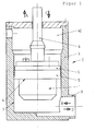
- Fig. 1 is a piston 1 for a metering pump 2 for dosing flowable contents, in particular food under sterile conditions shown.
- the metering pump 2 is a piston-cylinder unit, comprising a piston 1, a coaxial metallic piston rod 4 and a cylinder 3, wherein the piston 1 has a metallic piston core as inner part 10 and a radially extended piston guide 5 as outer part 9, the one truncated cone-shaped collar 5 'made of plastic having an annular sealing lip 6, which is determined to hermetically seal with its largest diameter on the cylinder inner surface 7 of the cylinder 3 of the piston-cylinder unit to slide back and forth, wherein the sealing lip 6 having region of the outer part 9 surrounds the inner part 10 with the interposition of a spring.
- the region of the piston 1 having the sealing lip 6 consists of a plastic, in particular of PTFE (polytetrafluoroethylene).
- This metering pump 2 sucks in a movement of the piston 1 in the direction of arrow A a certain amount of flowable contents from a reservoir, not shown, through a suction and filler 8 in the direction of arrow B. In a subsequent movement of the piston 1 in the direction of arrow C, this amount is discharged again through the suction and filler 8 in the direction of arrow D in a container, not shown.
- the required valve with its ways on the one hand to the reservoir and on the other hand to the container is also not shown.
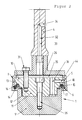
- the piston rod 4 has a coaxial opening 32 in the piston rod 4 as a channel 33 to a in Distance from the piston 1 arranged opening 34 leads to the outside area, said opening 32 is connected to a disc-shaped radial cavity 35 between the inner part 10 and outer part 9 of the piston 1, which cavity 35 in turn via at least one passage 36 with a sealing lip 6 adjacent Annulus 18 is in communication, such that on the one hand pressure equalization between the annulus 18 and opening 34 can take place, and that on the other hand, in a leaking of the sealing lip 6 by a crack in itself or in one of the adjoining walls 13, 14 or by their wear occurring over time, the flowable medium via the annular space 18 and the channel 33 can escape from the opening 34 and can be visible, and that the spring is a spring arranged in the annular space.
- An additional advantage of the piston 1 according to the invention is that already during the first sterilization of the piston 1 of the just-built metering pump 2 and before the start of the actual function of the metering pump 2 by sucking and filling a product dose of the substance or the filling material to be controlled the perfect sealing function of the piston 1 can be done.
- the piston 1 is namely in its sterilization position, not shown, above in the space 42 of the cylinder 3 of the metering pump 2 ( Fig. 1 ) and exposed to the sterilizing fluid in the form of vapor or liquid, its eventual leakage would be indicated by leakage of the fluid from the lateral opening 34.
- the piston 1 consists in two parts of a sealing lip 6 having and an extended portion 5 forming a piston guide separate outer part 9 made of plastic and the piston core forming inner part 10 made of metal, preferably stainless steel, on which the piston rod 4 is coaxially arranged, which inner part 10 is formed substantially frusto-conical and is inserted with its smaller diameter end 11 in a forward receiving him rotationally symmetrical recess 12 of the outer part 9.
- the recess 12 is expediently hollowed out so as to form the cavity 35 and the annular space 18 such that the regions of the outer part 9 which adjoin the sealing lip 6 and close the annular space 18 to the outside have a substantially axial wall 13 and a substantially radial wall 14 form, and wherein these two walls (13, 14) are so flexible that the sealing lip (6) under the action of the in the annular space (18) associated recess (12) between the adjacent to the sealing lip (6) axial wall ( 13) of the outer part (9) and a frusto-conical annular wall surface (15) of the inner part (10) clamped spring (16) radially both outwardly biased and upon insertion of the piston (1) in the cylinder (3) of the piston-cylinder unit under the narrowing effect of the cylinder inner surface (7) is resilient radially inward.
- the radially extending wall 14 expediently at least one circumferentially circumferential, extending into the annular space 18 and radially flexible fold 17 which facilitates a radial movement of the sealing lip 6 in the manner of a bellows.
- the essentially radial wall 14 with its single fold 17 which is expedient here can be formed because the free end 9 'of the outer part 9 is correspondingly reduced in diameter relative to the diameter of the sealing lip 6.
- the radial wall 14 practically consists only of the fold 17th
- the spring 16 is arranged in the part of the recess 12 forming annular space 18 between the inner part 9 and the outer part 10 and here is for example an annular spring. It has an inverted U-shaped axial cross section with radially inner webs 19 and radially outer webs 20 and web connections 21.
- the radially inner webs 19 engage on the frusto-conical annular wall surface 15 of the inner part 10 and the radially outer webs 20 engage the substantially axially extending and adjacent to the sealing lip 6 inner surface 22 of the axial wall 13 of the outer part 9.
- the bias of the annular spring 16 can be generated by coaxial displacement of the inner part 10 in the outer part 9 into it. In this case, two surfaces hold the annular spring 16 in position, namely a collar surface 15 ', the pressure exerted from above, and the frustoconical Ring wall surface 15 as an inclined surface, which is ultimately responsible for the bias of the sealing lip 6.
- the spring 16 has at least one passage 41, such that upon leakage of the sealing lip 6, a passage of the filling material, not shown to at least one passage 36 between the cavity 35 and a connection channel 40 is ensured.
- this embodiment of the spring 16 in the circumferential direction and at a distance from each other on a plurality of passages 41, which extend over the entire circumference of the spring 16.
- the spring 16 has in this case in the circumferential direction two opposite ends and a distance T from each other having ends 42 and 43, said distance T also forms a passage.
- the passages 41 are here cutouts which extend from the web connections 21 of the U to the edges 19 'and 20' of the webs 19, 20 of the spring 16.
- the webs 19 and 20 are provided at their edges 19 'and 20' out with a spread, with only the edges 20 'of the radially outer web 20 bear against the inner surface 22 of the axial wall 13 while doing line contact, while the radially inner webs 19 abut flat against the frustoconical ring wall surface 15 of the inner part 10.
- a slip-stick effect between the sealing lip 6 and the cylinder inner surface 7 can be avoided in the subject matter of the invention by selecting a suitable spring strength of the annular spring 16 and thus by a variation of the contact pressure, because, for example, in the filling of a high-viscosity filling with less lubrication, the contact pressure the sealing lip 6 against the cylinder inner surface 7 select by reducing the spring force correspondingly lower.
- the dimensions are such that the end face 10 a of the inner part 10 bears against the inner end face 9 a of the outer part 9.
- inner part 10 and outer part 9 are connected to each other by means of a screw.
- This screw connection consists here of a central screw 25, which penetrates the inner part 10, rests with its head 26 in a recess 27 of the inner part 10 and is screwed with its threaded portion 28 in a coaxial blind thread 29 of the outer part 9.
- the piston rod 4 here has a coaxial end plate 30 which is fixedly connected to the inner part 10, wherein the compound consists of a screw connection with at least one screw 31 here.
- the cavity 35 is formed between the end plate 30 and the inner part 10, and at least one passage 36 is provided in the inner part 10 between this cavity 35 and a connection channel 40 in an end face 10a of the inner part 10, which connection channel 40 in this way with the opening 34 is connected, such that a passage between the annular space 18 of the recess 12 and the opening 34 is present.
- the flexibility and spring force of the annular spring 16 can be changed and adapted to different filling media.
- outer part 9 and inner part 10 touch only in two areas, namely on the one hand in the region of the end surface 10a of the inner part 10, which abuts against the inner end surface 9a of the outer part 9, and on the other in the region of the collar 23 of the outer part 9, which engages over the upper edge 24 of the inner part 10. Between these two areas, the outer part 9 and the inner part 10 maintain a distance from each other, which ensures the open connection between the annular space 18 and the opening 34, such that in the manner explained on the one hand pressure equalization and on the other hand a leak indicator is ensured.
- the inner part 10 is bevelled inwardly towards the end surface 10a towards the inside to form the frusto-conical inner wall surface 15 and the collar surface 15 'for the clamping of the annular spring 16.
- the annular space 18 extends axially to the cavity 35 through the spring 16 also and in the area of this extension it provides in the Fig. 2 to 4 shown possibility to arrange at least one open connection 44 between the annular space 18 and the passage 36, which ensures a passage of contents to the opening 34, even if the configuration of the respective spring 16 a passage of the filling material past her or through it, as is the case with the spring 16 described above, not possible.
- This open connection 44 is expediently at least one bore.
Landscapes
- Engineering & Computer Science (AREA)
- Mechanical Engineering (AREA)
- General Engineering & Computer Science (AREA)
- Chemical & Material Sciences (AREA)
- Combustion & Propulsion (AREA)
- Details Of Reciprocating Pumps (AREA)
- Pistons, Piston Rings, And Cylinders (AREA)
Applications Claiming Priority (1)
| Application Number | Priority Date | Filing Date | Title |
|---|---|---|---|
| DE102014007221.5A DE102014007221A1 (de) | 2014-05-19 | 2014-05-19 | Kolben für eine Dosierpumpe zum Dosieren von fließfähigem Füllgut |
Publications (2)
| Publication Number | Publication Date |
|---|---|
| EP2949930A1 true EP2949930A1 (fr) | 2015-12-02 |
| EP2949930B1 EP2949930B1 (fr) | 2017-08-23 |
Family
ID=53188847
Family Applications (1)
| Application Number | Title | Priority Date | Filing Date |
|---|---|---|---|
| EP15001487.6A Not-in-force EP2949930B1 (fr) | 2014-05-19 | 2015-05-18 | Piston pour une pompe de dosage |
Country Status (2)
| Country | Link |
|---|---|
| EP (1) | EP2949930B1 (fr) |
| DE (1) | DE102014007221A1 (fr) |
Cited By (1)
| Publication number | Priority date | Publication date | Assignee | Title |
|---|---|---|---|---|
| EP3616529A1 (fr) * | 2018-08-29 | 2020-03-04 | INDAG Pouch Partners GmbH | Pompe doseuse de refouleur et utilisation de la pompe doseuse de refouleur |
Families Citing this family (3)
| Publication number | Priority date | Publication date | Assignee | Title |
|---|---|---|---|---|
| DE102019110649B4 (de) * | 2019-04-25 | 2020-11-26 | Holac Maschinenbau Gmbh | Stempel zum Bewegen eines zu verarbeitenden Produkts und Vorrichtung zum Verarbeiten eines zu verarbeitenden Produkts |
| DE102023101410A1 (de) * | 2023-01-20 | 2024-07-25 | Elringklinger Ag | Dosierkolben |
| DE102024126433A1 (de) | 2024-09-13 | 2026-03-19 | Ulman Dichtungstechnik Gmbh | Dosierkolben für eine Dosierpumpe |
Citations (4)
| Publication number | Priority date | Publication date | Assignee | Title |
|---|---|---|---|---|
| US2600516A (en) * | 1948-10-27 | 1952-06-17 | Jr William E Pielop | Slush pump piston and rod assembly |
| DE2354771A1 (de) * | 1973-11-02 | 1975-05-07 | Gerd Wolfgang Schellenberg | Kolbenpumpe, insbesondere zum foerdern von beton und anderen breiigen massen |
| DE3010010A1 (de) * | 1980-03-15 | 1981-09-24 | Lieder Maschinenbau GmbH & Co KG, 3033 Schwarmstedt | Drehschieber |
| DE8908291U1 (de) * | 1989-07-07 | 1989-08-31 | IDG-Dichtungstechnik GmbH, 7312 Kirchheim | Dosierkolben |
Family Cites Families (3)
| Publication number | Priority date | Publication date | Assignee | Title |
|---|---|---|---|---|
| US3962956A (en) * | 1974-11-19 | 1976-06-15 | Greer Hydraulics, Inc. | Hydropneumatic valve actuator |
| DE8814480U1 (de) * | 1988-11-19 | 1989-03-02 | Korthaus, Ernst, Dipl.-Ing., 5982 Neuenrade | Abdichteinheit für Kolbenpumpen |
| DE102012104710A1 (de) * | 2012-05-31 | 2013-12-05 | Krones Ag | Vorrichtung zum Heben von Behältern |
-
2014
- 2014-05-19 DE DE102014007221.5A patent/DE102014007221A1/de not_active Withdrawn
-
2015
- 2015-05-18 EP EP15001487.6A patent/EP2949930B1/fr not_active Not-in-force
Patent Citations (4)
| Publication number | Priority date | Publication date | Assignee | Title |
|---|---|---|---|---|
| US2600516A (en) * | 1948-10-27 | 1952-06-17 | Jr William E Pielop | Slush pump piston and rod assembly |
| DE2354771A1 (de) * | 1973-11-02 | 1975-05-07 | Gerd Wolfgang Schellenberg | Kolbenpumpe, insbesondere zum foerdern von beton und anderen breiigen massen |
| DE3010010A1 (de) * | 1980-03-15 | 1981-09-24 | Lieder Maschinenbau GmbH & Co KG, 3033 Schwarmstedt | Drehschieber |
| DE8908291U1 (de) * | 1989-07-07 | 1989-08-31 | IDG-Dichtungstechnik GmbH, 7312 Kirchheim | Dosierkolben |
Cited By (3)
| Publication number | Priority date | Publication date | Assignee | Title |
|---|---|---|---|---|
| EP3616529A1 (fr) * | 2018-08-29 | 2020-03-04 | INDAG Pouch Partners GmbH | Pompe doseuse de refouleur et utilisation de la pompe doseuse de refouleur |
| WO2020043471A1 (fr) * | 2018-08-29 | 2020-03-05 | Indag Pouch Partners Gmbh | Pompe de dosage à déplacement et utilisation de la pompe de dosage à déplacement |
| US11802550B2 (en) | 2018-08-29 | 2023-10-31 | Indag Pouch Partners Gmbh | Displacement metering pump and use of the displacement metering pump |
Also Published As
| Publication number | Publication date |
|---|---|
| EP2949930B1 (fr) | 2017-08-23 |
| DE102014007221A1 (de) | 2015-11-19 |
Similar Documents
| Publication | Publication Date | Title |
|---|---|---|
| EP3090196B1 (fr) | Soupape | |
| DE2759943C2 (de) | Dichtungsanordnung für die Kolbenstange eines Stoßdämpfers | |
| DE3320515C1 (de) | Hochdruckdichtung fuer laengsverschieblich gegeneinander bewegbare Teile von Tiefbohrwerkzeugen | |
| DE102012108566B4 (de) | Steckereinheit und Verbindungseinrichtung für Flüssigkeit führende Komponenten, insbesondere für die Hochleistungsflüssigkeitschromatographie | |
| EP3218623B1 (fr) | Système d'étanchéité | |
| EP2949930B1 (fr) | Piston pour une pompe de dosage | |
| EP2397727A1 (fr) | Tête de soupape en plusieurs parties | |
| DE4032921C2 (de) | Hochleistungsgasdruckfeder | |
| EP3724530B1 (fr) | Actionneur d'embrayage servant à actionner l'embrayage d'un véhicule | |
| EP2831419B1 (fr) | Système d'étanchéité | |
| DE3339098C2 (de) | Kraftstoffeinspritzpumpe | |
| DE2204162B2 (de) | Spaltdichtung für die Abdichtung hin- und hergehender Maschinenteile | |
| EP2203667B1 (fr) | Soupape a double siege avec possibilite de nettoyage de siege et procede de nettoyage de cette soupape | |
| DE2248156A1 (de) | Dichtungseinrichtung | |
| DE2816930C2 (de) | Stopfbuchsdichtung | |
| EP3714992B1 (fr) | Dispositif de distribution d'un fluide coulant ainsi que procédé de fonctionnement d'un tel dispositif | |
| DE112014006785B4 (de) | Arbeitszylinder | |
| DE2336118C3 (fr) | ||
| EP1769176B1 (fr) | Ensemble d'etancheite | |
| DE102021100029A1 (de) | Arretiersystem | |
| DE2905724C2 (de) | Stangen-Dichtung | |
| DE29507638U1 (de) | Ventil | |
| EP0410196A1 (fr) | Dispositif de longueur ajustable | |
| DE112016002191T5 (de) | Hydraulikzylinder | |
| EP0965009B1 (fr) | Dispositif de piston a pression comprenant une garniture d'etancheite |
Legal Events
| Date | Code | Title | Description |
|---|---|---|---|
| 17P | Request for examination filed |
Effective date: 20150529 |
|
| AK | Designated contracting states |
Kind code of ref document: A1 Designated state(s): AL AT BE BG CH CY CZ DE DK EE ES FI FR GB GR HR HU IE IS IT LI LT LU LV MC MK MT NL NO PL PT RO RS SE SI SK SM TR |
|
| AX | Request for extension of the european patent |
Extension state: BA ME |
|
| PUAI | Public reference made under article 153(3) epc to a published international application that has entered the european phase |
Free format text: ORIGINAL CODE: 0009012 |
|
| 17Q | First examination report despatched |
Effective date: 20160201 |
|
| GRAP | Despatch of communication of intention to grant a patent |
Free format text: ORIGINAL CODE: EPIDOSNIGR1 |
|
| INTG | Intention to grant announced |
Effective date: 20161207 |
|
| GRAJ | Information related to disapproval of communication of intention to grant by the applicant or resumption of examination proceedings by the epo deleted |
Free format text: ORIGINAL CODE: EPIDOSDIGR1 |
|
| GRAP | Despatch of communication of intention to grant a patent |
Free format text: ORIGINAL CODE: EPIDOSNIGR1 |
|
| INTC | Intention to grant announced (deleted) | ||
| INTG | Intention to grant announced |
Effective date: 20170213 |
|
| GRAS | Grant fee paid |
Free format text: ORIGINAL CODE: EPIDOSNIGR3 |
|
| GRAA | (expected) grant |
Free format text: ORIGINAL CODE: 0009210 |
|
| AK | Designated contracting states |
Kind code of ref document: B1 Designated state(s): AL AT BE BG CH CY CZ DE DK EE ES FI FR GB GR HR HU IE IS IT LI LT LU LV MC MK MT NL NO PL PT RO RS SE SI SK SM TR |
|
| REG | Reference to a national code |
Ref country code: GB Ref legal event code: FG4D Free format text: NOT ENGLISH |
|
| REG | Reference to a national code |
Ref country code: CH Ref legal event code: EP |
|
| REG | Reference to a national code |
Ref country code: AT Ref legal event code: REF Ref document number: 921641 Country of ref document: AT Kind code of ref document: T Effective date: 20170915 |
|
| REG | Reference to a national code |
Ref country code: IE Ref legal event code: FG4D Free format text: LANGUAGE OF EP DOCUMENT: GERMAN |
|
| REG | Reference to a national code |
Ref country code: DE Ref legal event code: R096 Ref document number: 502015001702 Country of ref document: DE |
|
| REG | Reference to a national code |
Ref country code: NL Ref legal event code: MP Effective date: 20170823 |
|
| REG | Reference to a national code |
Ref country code: LT Ref legal event code: MG4D |
|
| PG25 | Lapsed in a contracting state [announced via postgrant information from national office to epo] |
Ref country code: HR Free format text: LAPSE BECAUSE OF FAILURE TO SUBMIT A TRANSLATION OF THE DESCRIPTION OR TO PAY THE FEE WITHIN THE PRESCRIBED TIME-LIMIT Effective date: 20170823 Ref country code: NL Free format text: LAPSE BECAUSE OF FAILURE TO SUBMIT A TRANSLATION OF THE DESCRIPTION OR TO PAY THE FEE WITHIN THE PRESCRIBED TIME-LIMIT Effective date: 20170823 Ref country code: FI Free format text: LAPSE BECAUSE OF FAILURE TO SUBMIT A TRANSLATION OF THE DESCRIPTION OR TO PAY THE FEE WITHIN THE PRESCRIBED TIME-LIMIT Effective date: 20170823 Ref country code: LT Free format text: LAPSE BECAUSE OF FAILURE TO SUBMIT A TRANSLATION OF THE DESCRIPTION OR TO PAY THE FEE WITHIN THE PRESCRIBED TIME-LIMIT Effective date: 20170823 Ref country code: NO Free format text: LAPSE BECAUSE OF FAILURE TO SUBMIT A TRANSLATION OF THE DESCRIPTION OR TO PAY THE FEE WITHIN THE PRESCRIBED TIME-LIMIT Effective date: 20171123 Ref country code: SE Free format text: LAPSE BECAUSE OF FAILURE TO SUBMIT A TRANSLATION OF THE DESCRIPTION OR TO PAY THE FEE WITHIN THE PRESCRIBED TIME-LIMIT Effective date: 20170823 |
|
| PG25 | Lapsed in a contracting state [announced via postgrant information from national office to epo] |
Ref country code: LV Free format text: LAPSE BECAUSE OF FAILURE TO SUBMIT A TRANSLATION OF THE DESCRIPTION OR TO PAY THE FEE WITHIN THE PRESCRIBED TIME-LIMIT Effective date: 20170823 Ref country code: GR Free format text: LAPSE BECAUSE OF FAILURE TO SUBMIT A TRANSLATION OF THE DESCRIPTION OR TO PAY THE FEE WITHIN THE PRESCRIBED TIME-LIMIT Effective date: 20171124 Ref country code: RS Free format text: LAPSE BECAUSE OF FAILURE TO SUBMIT A TRANSLATION OF THE DESCRIPTION OR TO PAY THE FEE WITHIN THE PRESCRIBED TIME-LIMIT Effective date: 20170823 Ref country code: BG Free format text: LAPSE BECAUSE OF FAILURE TO SUBMIT A TRANSLATION OF THE DESCRIPTION OR TO PAY THE FEE WITHIN THE PRESCRIBED TIME-LIMIT Effective date: 20171123 Ref country code: ES Free format text: LAPSE BECAUSE OF FAILURE TO SUBMIT A TRANSLATION OF THE DESCRIPTION OR TO PAY THE FEE WITHIN THE PRESCRIBED TIME-LIMIT Effective date: 20170823 Ref country code: PL Free format text: LAPSE BECAUSE OF FAILURE TO SUBMIT A TRANSLATION OF THE DESCRIPTION OR TO PAY THE FEE WITHIN THE PRESCRIBED TIME-LIMIT Effective date: 20170823 Ref country code: IS Free format text: LAPSE BECAUSE OF FAILURE TO SUBMIT A TRANSLATION OF THE DESCRIPTION OR TO PAY THE FEE WITHIN THE PRESCRIBED TIME-LIMIT Effective date: 20171223 |
|
| PG25 | Lapsed in a contracting state [announced via postgrant information from national office to epo] |
Ref country code: DK Free format text: LAPSE BECAUSE OF FAILURE TO SUBMIT A TRANSLATION OF THE DESCRIPTION OR TO PAY THE FEE WITHIN THE PRESCRIBED TIME-LIMIT Effective date: 20170823 Ref country code: RO Free format text: LAPSE BECAUSE OF FAILURE TO SUBMIT A TRANSLATION OF THE DESCRIPTION OR TO PAY THE FEE WITHIN THE PRESCRIBED TIME-LIMIT Effective date: 20170823 Ref country code: CZ Free format text: LAPSE BECAUSE OF FAILURE TO SUBMIT A TRANSLATION OF THE DESCRIPTION OR TO PAY THE FEE WITHIN THE PRESCRIBED TIME-LIMIT Effective date: 20170823 |
|
| REG | Reference to a national code |
Ref country code: FR Ref legal event code: PLFP Year of fee payment: 4 |
|
| REG | Reference to a national code |
Ref country code: DE Ref legal event code: R097 Ref document number: 502015001702 Country of ref document: DE |
|
| PG25 | Lapsed in a contracting state [announced via postgrant information from national office to epo] |
Ref country code: SM Free format text: LAPSE BECAUSE OF FAILURE TO SUBMIT A TRANSLATION OF THE DESCRIPTION OR TO PAY THE FEE WITHIN THE PRESCRIBED TIME-LIMIT Effective date: 20170823 Ref country code: SK Free format text: LAPSE BECAUSE OF FAILURE TO SUBMIT A TRANSLATION OF THE DESCRIPTION OR TO PAY THE FEE WITHIN THE PRESCRIBED TIME-LIMIT Effective date: 20170823 Ref country code: EE Free format text: LAPSE BECAUSE OF FAILURE TO SUBMIT A TRANSLATION OF THE DESCRIPTION OR TO PAY THE FEE WITHIN THE PRESCRIBED TIME-LIMIT Effective date: 20170823 Ref country code: IT Free format text: LAPSE BECAUSE OF FAILURE TO SUBMIT A TRANSLATION OF THE DESCRIPTION OR TO PAY THE FEE WITHIN THE PRESCRIBED TIME-LIMIT Effective date: 20170823 |
|
| PLBE | No opposition filed within time limit |
Free format text: ORIGINAL CODE: 0009261 |
|
| STAA | Information on the status of an ep patent application or granted ep patent |
Free format text: STATUS: NO OPPOSITION FILED WITHIN TIME LIMIT |
|
| 26N | No opposition filed |
Effective date: 20180524 |
|
| PG25 | Lapsed in a contracting state [announced via postgrant information from national office to epo] |
Ref country code: SI Free format text: LAPSE BECAUSE OF FAILURE TO SUBMIT A TRANSLATION OF THE DESCRIPTION OR TO PAY THE FEE WITHIN THE PRESCRIBED TIME-LIMIT Effective date: 20170823 |
|
| PG25 | Lapsed in a contracting state [announced via postgrant information from national office to epo] |
Ref country code: MT Free format text: LAPSE BECAUSE OF FAILURE TO SUBMIT A TRANSLATION OF THE DESCRIPTION OR TO PAY THE FEE WITHIN THE PRESCRIBED TIME-LIMIT Effective date: 20170823 |
|
| REG | Reference to a national code |
Ref country code: BE Ref legal event code: MM Effective date: 20180531 |
|
| PG25 | Lapsed in a contracting state [announced via postgrant information from national office to epo] |
Ref country code: MC Free format text: LAPSE BECAUSE OF FAILURE TO SUBMIT A TRANSLATION OF THE DESCRIPTION OR TO PAY THE FEE WITHIN THE PRESCRIBED TIME-LIMIT Effective date: 20170823 |
|
| REG | Reference to a national code |
Ref country code: IE Ref legal event code: MM4A |
|
| PG25 | Lapsed in a contracting state [announced via postgrant information from national office to epo] |
Ref country code: LU Free format text: LAPSE BECAUSE OF NON-PAYMENT OF DUE FEES Effective date: 20180518 |
|
| PG25 | Lapsed in a contracting state [announced via postgrant information from national office to epo] |
Ref country code: IE Free format text: LAPSE BECAUSE OF NON-PAYMENT OF DUE FEES Effective date: 20180518 |
|
| PG25 | Lapsed in a contracting state [announced via postgrant information from national office to epo] |
Ref country code: BE Free format text: LAPSE BECAUSE OF NON-PAYMENT OF DUE FEES Effective date: 20180531 |
|
| PG25 | Lapsed in a contracting state [announced via postgrant information from national office to epo] |
Ref country code: TR Free format text: LAPSE BECAUSE OF FAILURE TO SUBMIT A TRANSLATION OF THE DESCRIPTION OR TO PAY THE FEE WITHIN THE PRESCRIBED TIME-LIMIT Effective date: 20170823 |
|
| PG25 | Lapsed in a contracting state [announced via postgrant information from national office to epo] |
Ref country code: PT Free format text: LAPSE BECAUSE OF FAILURE TO SUBMIT A TRANSLATION OF THE DESCRIPTION OR TO PAY THE FEE WITHIN THE PRESCRIBED TIME-LIMIT Effective date: 20170823 |
|
| PG25 | Lapsed in a contracting state [announced via postgrant information from national office to epo] |
Ref country code: CY Free format text: LAPSE BECAUSE OF FAILURE TO SUBMIT A TRANSLATION OF THE DESCRIPTION OR TO PAY THE FEE WITHIN THE PRESCRIBED TIME-LIMIT Effective date: 20170823 Ref country code: MK Free format text: LAPSE BECAUSE OF NON-PAYMENT OF DUE FEES Effective date: 20170823 Ref country code: HU Free format text: LAPSE BECAUSE OF FAILURE TO SUBMIT A TRANSLATION OF THE DESCRIPTION OR TO PAY THE FEE WITHIN THE PRESCRIBED TIME-LIMIT; INVALID AB INITIO Effective date: 20150518 |
|
| PG25 | Lapsed in a contracting state [announced via postgrant information from national office to epo] |
Ref country code: AL Free format text: LAPSE BECAUSE OF FAILURE TO SUBMIT A TRANSLATION OF THE DESCRIPTION OR TO PAY THE FEE WITHIN THE PRESCRIBED TIME-LIMIT Effective date: 20170823 |
|
| PGFP | Annual fee paid to national office [announced via postgrant information from national office to epo] |
Ref country code: FR Payment date: 20200519 Year of fee payment: 6 Ref country code: CH Payment date: 20200522 Year of fee payment: 6 |
|
| PGFP | Annual fee paid to national office [announced via postgrant information from national office to epo] |
Ref country code: GB Payment date: 20200522 Year of fee payment: 6 |
|
| PGFP | Annual fee paid to national office [announced via postgrant information from national office to epo] |
Ref country code: AT Payment date: 20200515 Year of fee payment: 6 |
|
| PGFP | Annual fee paid to national office [announced via postgrant information from national office to epo] |
Ref country code: DE Payment date: 20200717 Year of fee payment: 6 |
|
| REG | Reference to a national code |
Ref country code: DE Ref legal event code: R119 Ref document number: 502015001702 Country of ref document: DE |
|
| REG | Reference to a national code |
Ref country code: CH Ref legal event code: PL |
|
| REG | Reference to a national code |
Ref country code: AT Ref legal event code: MM01 Ref document number: 921641 Country of ref document: AT Kind code of ref document: T Effective date: 20210518 |
|
| GBPC | Gb: european patent ceased through non-payment of renewal fee |
Effective date: 20210518 |
|
| PG25 | Lapsed in a contracting state [announced via postgrant information from national office to epo] |
Ref country code: CH Free format text: LAPSE BECAUSE OF NON-PAYMENT OF DUE FEES Effective date: 20210531 Ref country code: AT Free format text: LAPSE BECAUSE OF NON-PAYMENT OF DUE FEES Effective date: 20210518 Ref country code: LI Free format text: LAPSE BECAUSE OF NON-PAYMENT OF DUE FEES Effective date: 20210531 |
|
| PG25 | Lapsed in a contracting state [announced via postgrant information from national office to epo] |
Ref country code: GB Free format text: LAPSE BECAUSE OF NON-PAYMENT OF DUE FEES Effective date: 20210518 Ref country code: DE Free format text: LAPSE BECAUSE OF NON-PAYMENT OF DUE FEES Effective date: 20211201 |
|
| PG25 | Lapsed in a contracting state [announced via postgrant information from national office to epo] |
Ref country code: FR Free format text: LAPSE BECAUSE OF NON-PAYMENT OF DUE FEES Effective date: 20210531 |