EP2949971B1 - Véhicule de travail - Google Patents
Véhicule de travail Download PDFInfo
- Publication number
- EP2949971B1 EP2949971B1 EP15168916.3A EP15168916A EP2949971B1 EP 2949971 B1 EP2949971 B1 EP 2949971B1 EP 15168916 A EP15168916 A EP 15168916A EP 2949971 B1 EP2949971 B1 EP 2949971B1
- Authority
- EP
- European Patent Office
- Prior art keywords
- speed
- vehicle
- changing
- auto
- instruction
- Prior art date
- Legal status (The legal status is an assumption and is not a legal conclusion. Google has not performed a legal analysis and makes no representation as to the accuracy of the status listed.)
- Active
Links
Images




Classifications
-
- F—MECHANICAL ENGINEERING; LIGHTING; HEATING; WEAPONS; BLASTING
- F16—ENGINEERING ELEMENTS AND UNITS; GENERAL MEASURES FOR PRODUCING AND MAINTAINING EFFECTIVE FUNCTIONING OF MACHINES OR INSTALLATIONS; THERMAL INSULATION IN GENERAL
- F16H—GEARING
- F16H61/00—Control functions within control units of change-speed- or reversing-gearings for conveying rotary motion ; Control of exclusively fluid gearing, friction gearing, gearings with endless flexible members or other particular types of gearing
- F16H61/38—Control of exclusively fluid gearing
- F16H61/40—Control of exclusively fluid gearing hydrostatic
- F16H61/46—Automatic regulation in accordance with output requirements
- F16H61/47—Automatic regulation in accordance with output requirements for achieving a target output speed
-
- B—PERFORMING OPERATIONS; TRANSPORTING
- B60—VEHICLES IN GENERAL
- B60K—ARRANGEMENT OR MOUNTING OF PROPULSION UNITS OR OF TRANSMISSIONS IN VEHICLES; ARRANGEMENT OR MOUNTING OF PLURAL DIVERSE PRIME-MOVERS IN VEHICLES; AUXILIARY DRIVES FOR VEHICLES; INSTRUMENTATION OR DASHBOARDS FOR VEHICLES; ARRANGEMENTS IN CONNECTION WITH COOLING, AIR INTAKE, GAS EXHAUST OR FUEL SUPPLY OF PROPULSION UNITS IN VEHICLES
- B60K31/00—Vehicle fittings, acting on a single sub-unit only, for automatically controlling vehicle speed, i.e. preventing speed from exceeding an arbitrarily established velocity or maintaining speed at a particular velocity, as selected by the vehicle operator
- B60K31/02—Vehicle fittings, acting on a single sub-unit only, for automatically controlling vehicle speed, i.e. preventing speed from exceeding an arbitrarily established velocity or maintaining speed at a particular velocity, as selected by the vehicle operator including electrically actuated servomechanism
- B60K31/04—Vehicle fittings, acting on a single sub-unit only, for automatically controlling vehicle speed, i.e. preventing speed from exceeding an arbitrarily established velocity or maintaining speed at a particular velocity, as selected by the vehicle operator including electrically actuated servomechanism and means for comparing one electrical quantity, e.g. voltage, pulse, waveform, flux, or the like, with another quantity of a like kind, which comparison means is involved in the development of an electrical signal which is fed into the controlling means
- B60K31/042—Vehicle fittings, acting on a single sub-unit only, for automatically controlling vehicle speed, i.e. preventing speed from exceeding an arbitrarily established velocity or maintaining speed at a particular velocity, as selected by the vehicle operator including electrically actuated servomechanism and means for comparing one electrical quantity, e.g. voltage, pulse, waveform, flux, or the like, with another quantity of a like kind, which comparison means is involved in the development of an electrical signal which is fed into the controlling means where at least one electrical quantity is set by the vehicle operator
-
- B—PERFORMING OPERATIONS; TRANSPORTING
- B60—VEHICLES IN GENERAL
- B60W—CONJOINT CONTROL OF VEHICLE SUB-UNITS OF DIFFERENT TYPE OR DIFFERENT FUNCTION; CONTROL SYSTEMS SPECIALLY ADAPTED FOR HYBRID VEHICLES; ROAD VEHICLE DRIVE CONTROL SYSTEMS FOR PURPOSES NOT RELATED TO THE CONTROL OF A PARTICULAR SUB-UNIT
- B60W30/00—Purposes of road vehicle drive control systems not related to the control of a particular sub-unit, e.g. of systems using conjoint control of vehicle sub-units
- B60W30/14—Adaptive cruise control
- B60W30/143—Speed control
-
- B—PERFORMING OPERATIONS; TRANSPORTING
- B60—VEHICLES IN GENERAL
- B60K—ARRANGEMENT OR MOUNTING OF PROPULSION UNITS OR OF TRANSMISSIONS IN VEHICLES; ARRANGEMENT OR MOUNTING OF PLURAL DIVERSE PRIME-MOVERS IN VEHICLES; AUXILIARY DRIVES FOR VEHICLES; INSTRUMENTATION OR DASHBOARDS FOR VEHICLES; ARRANGEMENTS IN CONNECTION WITH COOLING, AIR INTAKE, GAS EXHAUST OR FUEL SUPPLY OF PROPULSION UNITS IN VEHICLES
- B60K2310/00—Arrangements, adaptations or methods for cruise controls
- B60K2310/24—Speed setting methods
- B60K2310/244—Speed setting methods changing target speed or setting a new target speed, e.g. changing algorithms
-
- B—PERFORMING OPERATIONS; TRANSPORTING
- B60—VEHICLES IN GENERAL
- B60W—CONJOINT CONTROL OF VEHICLE SUB-UNITS OF DIFFERENT TYPE OR DIFFERENT FUNCTION; CONTROL SYSTEMS SPECIALLY ADAPTED FOR HYBRID VEHICLES; ROAD VEHICLE DRIVE CONTROL SYSTEMS FOR PURPOSES NOT RELATED TO THE CONTROL OF A PARTICULAR SUB-UNIT
- B60W2300/00—Indexing codes relating to the type of vehicle
- B60W2300/15—Agricultural vehicles
- B60W2300/152—Tractors
-
- B—PERFORMING OPERATIONS; TRANSPORTING
- B60—VEHICLES IN GENERAL
- B60Y—INDEXING SCHEME RELATING TO ASPECTS CROSS-CUTTING VEHICLE TECHNOLOGY
- B60Y2200/00—Type of vehicle
- B60Y2200/20—Off-Road Vehicles
- B60Y2200/22—Agricultural vehicles
- B60Y2200/221—Tractors
Definitions
- the present invention relates to a working vehicle such as a tractor or the like which is for agriculture, for architecture, for transport, or the like.
- a tractor or the like which has an HST (an oil-hydrostatic type non-step transmission device) to travel and has an auto-cruise function (for example, refer to Japanese Patent Application Publication No. 2013-204783 , European Patent No. EP1177114B1 , and the like).
- HST an oil-hydrostatic type non-step transmission device
- a tractor of Japanese Patent Application Publication No. 2013-204783 has an HST of a two-stage type, and has a switching switch which switches the Hi and Lo of the HST oil-hydrostatic motor, a cruise speed-increasing switch and a cruise speed-decreasing switch for making slight increase/decrease of the vehicle-speed in an auto-cruise control state, and the like.
- An object of the present invention is, in consideration of a problem like this of a conventional tractor, to furnish a working vehicle for which the number of the switches is to be decreased.
- the 1 st aspect of the present invention is a working vehicle (200), comprising:
- the switching part since while the auto-cruise mode is in the ON state, the switching part switches to an increase/decrease switch which makes slight increase/decrease of the vehicle-speed in the auto-cruise mode state, the switching part can play two kinds of roles, and the number of the switches is to be decreased.
- the switching part since while the auto-cruise mode is in the ON state, the switching part switches to an increase/decrease switch which makes slight increase/decrease of the vehicle-speed in the auto-cruise mode state, the switching part can play two kinds of roles and the number of the switches is to be decreased.
- the switching part can surely play the intrinsic role.
- the 2 nd aspect of the present invention is the working vehicle (200) according to the above-mentioned 1 st aspect of the present invention, wherein the switching part (210) is a switching lever which is arranged on a periphery of a steering handle (7a) provided in the traveling-vehicle-body.
- the switching part is arranged on a periphery of the steering handle, switching manipulation is to be promptly and easily performed, and working efficiency improves. Moreover, since the switching part is a lever, the position of the lever can be easily checked, and manipulability improves.
- the 3 rd aspect of the present invention is the working vehicle (200) according to any of the above-mentioned 1 st or 2 nd aspect of the present invention, comprising:
- the 4 th aspect of the present invention is the working vehicle (200) according to the 1 st aspect, wherein
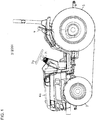
- FIG. 1 is an overall configuration side view of the tractor as one example of a working vehicle of the present invention
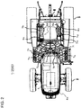
- FIG. 2 is an overall configuration plan view of the said tractor.
- the tractor 1 supports the machine-body by traveling-vehicle-wheels 2 and 3 of the front-and-rear in such a manner that farm field working is able to be carried out, and performs working with a working machine installed at the front part of the machine-body or the rear part.
- Motive force transmitting to the traveling-vehicle-wheels 2 and 3 is performed with motive force from an engine 4 received which is loaded inside an engine room 4a of the machine-body front part.
- non-step speed-changing transmission of the motive force is carried out for which speed-changing has been carried out at an auxiliary speed-changing mechanism 12 (stepped speed-changing) of a speed-changing device 5 and an oil-hydrostatic type non-step transmission device (an HST) 11.
- a working motive force supplying part 6 which is abbreviatedly called a PTO.
- the working motive force supplying part 6 is configured from a PTO mechanism 16a of the machine-body rear part and a PTO mechanism 16b of the machine-body central lower part.
- a steering handle 7a for traveling-manipulation are provided.
- an HST pedal 7b for traveling-manipulation are provided.
- a left-and-right set of brake pedals 7c used as the left brake pedal and the right brake pedal by connection canceling
- an auxiliary speed-changing lever 7d for traveling-manipulation is provided.
- a 4WD lever 7e which switches rear-wheel-driving and four-wheel-driving, an emergency stop switch 7f which carries out an emergency stop of the engine, a winker switch 7g, an auto-cruise switch 7h, and the like.
- PTO levers 8a and 8b of the rear and the mid Provided for working-machine-manipulation are PTO levers 8a and 8b of the rear and the mid, a position lever 8c which decides the ascending-and-descending position of the working machine being installed, a frontward/rearward movement lever 7i, a throttle lever 7j which sets up the engine rotation number, a bipartite outer part oil-hydrostatic lever 8d which drives another oil-hydrostatic instrument, and the like.
- the auxiliary speed-changing lever 7d is a lever which performs speed-changing manipulation of the auxiliary speed-changing mechanism 12 of stepped speed-changing shown in FIG 3 , and the configuration is such that three-stepped speed-changing is able to be carried out.
- FIG. 3 is a configuration expansion diagram of the transmission system of the tractor 1 of the present embodiment.
- the auto-cruise switch 7h gets into the ON state, and the configuration is such that even if the foot is released from the HST pedal 7b, the vehicle-speed at the point in time when the auto-cruise mode has been made to be in the ON state continues to be maintained.
- the configuration is such that, in the auto-cruise mode, the rotary-motion position of a trunnion shaft 21t is maintained which is for outputting adjustment of an oil-hydrostatic pump 21p of the non-step transmission device 11.
- the non-step transmission device 11 of an oil-hydrostatic type which receives engine motive force and is abbreviatedly called an HST, and the auxiliary speed-changing mechanism 12 which switches the vehicle-speed-ranges are serially arranged from the motive force transmitting upstream side to the downstream side, and transmission is carried out to a transmission mechanism 13 of the rear wheels 3 and the like (refer to FIG. 3 ).
- the speed-changing system is configured by a controlling part 100 which controls, based on the outputting from an HST pedal stepping-on-quantity detecting sensor 31 which detects the stepping-on-quantity of the HST pedal 7b by a speed-changing instructor such as the HST pedal 7b or the like, the oil-hydrostatic type non-step transmission device 11.
- a mode switching switch 32 which performs an instruction to switch various modes for distinguishing various kinds of working which include road-traveling, and the switching result of the modes by the mode switching switch 32 is outputted to the controlling part 100.
- the speed-changing device 5 has, as the transmission system expansion diagram is shown in FIG. 3 , traveling-system instruments by the oil-hydrostatic type non-step transmission device 11, the auxiliary speed-changing mechanism 12, the rear wheel transmission mechanism 13, a 4WD switching part 14a which leads to a front wheel transmission mechanism 14, and the like.
- Non-step speed-changing is carried out at the oil-hydrostatic type non-step transmission device 11 regarding each vehicle-speed-range by the auxiliary speed-changing mechanism 12 which selects a vehicle-speed-range in the range from the working-speed to the road-speed, and transmission outputting of the motive force for which the speed-changing has been carried out is carried out to the front-and-rear wheels 2 and 3.
- the motive force for which non-step speed-changing is not carried out makes, through a PTO clutch 15, from the PTO mechanisms 16a and 16b of the rear and the mid, the working machine operate.
- an outputting shaft 21a regarding the outputting from the engine 4 which has been inputted to the oil-hydrostatic type non-step transmission device 11 protrudes to the opposite side of the engine 4 (the side of the speed-changing device 5), and the configuration is such that via plural gears the motive force is transmitted to the PTO clutch 15.
- the configuration becomes such that the rear PTO mechanism 16a and the mid PTO mechanism 16b rotate with constant rotation.
- the reference numeral 11a denotes the charge pump of the oil-hydrostatic type non-step transmission device 11, and is internally installed inside the transmission case which encloses the speed-changing device 5.
- the rear PTO mechanism 16a drives a rotary, a snow-removing machine, a mower, or the like which is installed to the machine-body rear part.
- the mid PTO mechanism 16b drives a mower, a snow-removing machine, a road-cleaning machine, or the like which is installed to the machine-body lower part between the front wheels 2 and the rear wheels 3.
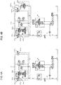
- the oil-hydrostatic type non-step transmission device 11 is, as the inner part configuration and the oil-hydrostatic circuit are shown in FIG. 4A , configured by the oil-hydrostatic pump 21p of a variable outputting type which is driven by engine motive force, and a constant-quantity oil-hydrostatic motor 21m which receives pump outputting of the oil-hydrostatic pump 21p.
- FIG. 4A is a diagram of the inner part configuration and the oil-hydrostatic circuit of the oil-hydrostatic type non-step transmission device 11.
- the oil-hydrostatic pump 21p is driven with direct connection with the outputting shaft 21a from the engine 4.
- the trunnion shaft 21t which is for outputting adjustment, and the angle of a swash plate 21s is changed with rotary-motion of the trunnion shaft 21t.
- the constant-quantity oil-hydrostatic motor 21m is driven, and carried out is transmission outputting of the normal/reverse speed-changing rotation motive force which includes neutrality in the sense of a stop of the outputting from an outputting shaft 21b of the constant-quantity oil-hydrostatic motor 21m.
- the configuration is made to be such that, by HST controlling of the servo mechanism, the operation-oil flowing-quantity is adjusted by the driving electric current to a proportional solenoid valve (including a trunnion frontward movement side solenoid, and a trunnion rearward movement side solenoid) 22.
- a proportional solenoid valve including a trunnion frontward movement side solenoid, and a trunnion rearward movement side solenoid 22.
- the controlling part 100 controls, as shown in FIG. 5 , corresponding to the mode which has been instructed by the mode switching switch 32, the changing-quantity of the rotary-motion angle of the trunnion shaft 21t of the oil-hydrostatic type non-step transmission device 11 with respect to the stepping-on-quantity which has been detected by the HST pedal stepping-on-quantity detecting sensor 31.
- FIG. 5 is an inputting-outputting block diagram which describes the controlling part 100 of the tractor 1 of the present embodiment.
- a switching valve 22a is configured at the downstream side of the proportional solenoid valve 22, and the configuration is made to be such that the rotary-motion direction of the trunnion shaft 21t, namely, the normal/reverse direction of the outputting shaft 21b is determined with the switching valve 22a.
- the reference numeral P shows the oil-hydrostatic circuit of the power steering.
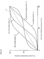
- FIG. 6 is a diagram which shows the relation between the HST pedal stepping-on-quantity and the operation-quantity of the trunnion shaft, which is determined beforehand corresponding to each working mode of the tractor 1 of the present embodiment.
- the relation between the HST pedal stepping-on-quantity and the operation-quantity of the trunnion shaft which is shown in FIG. 6 , is stored beforehand in a memory 110 (refer to FIG. 5 ).
- This mode is suitable for a case where, for example, road-traveling is carried out with a heavy working machine being towed.
- the controlling part 100 controls, corresponding to the low high-speed mode 111 which has been read out from the memory 110, the changing-quantity of the operation angle of the trunnion shaft 21t of the oil-hydrostatic type non-step transmission device 11 with respect to the stepping-on-quantity which has been detected by the HST pedal stepping-on-quantity detecting sensor 31.
- This mode is suitable for a case such as lawn mowing working or the like where, for example, working is carried out with traveling being carried out at constant speed.
- the controlling part 100 controls, corresponding to the intermediate-speed mode 112 which has been read out from the memory 110, the changing-quantity of the operation angle of the trunnion shaft 21t of the oil-hydrostatic type non-step transmission device 11 with respect to the stepping-on-quantity which has been detected by the HST pedal stepping-on-quantity detecting sensor 31.
- this mode is a mode suitable, for example, at the time of working-traveling in a farm field.
- the worker manipulates the mode switching switch 32 and sets up a high-speed mode 113, then the outputting is sent to the controlling part 100 and the correspondence relation, which is for the high-speed mode 113 and is stored in the memory 110, is read out.
- This mode is suitable for a case where, for example, road-traveling at high speed is carried out in a state without a working machine.
- the controlling part 100 controls, corresponding to the high-speed mode 113 which has been read out from the memory 110, the changing-quantity of the operation angle of the trunnion shaft 21t of the oil-hydrostatic type non-step transmission device 11 with respect to the stepping-on-quantity which has been detected by the HST pedal stepping-on-quantity detecting sensor 31.
- the worker manipulates the mode switching switch 32 and sets up a low-speed mode 114, then the outputting is sent to the controlling part 100 and the correspondence relation, which is for the low-speed mode 114 and is stored in the memory 110, is read out.
- This mode is suitable for a case where, for example, road-cleaning at low speed is carried out.
- the controlling part 100 controls, corresponding to the low-speed mode 114 which has been read out from the memory 110, the changing-quantity of the operation angle of the trunnion shaft 21t of the oil-hydrostatic type non-step transmission device 11 with respect to the stepping-on-quantity which has been detected by the HST pedal stepping-on-quantity detecting sensor 31.
- Second Embodiment to be described later descriptions will be given regarding a configuration where the mechanism which instructs switching of a stage switching valve 122 is of a lever type but, not being limited to this, for example, such a configuration of a push type may be allowed.
- each mode is set up by the mode switching switch 32 but, not being limited to this, for example, such a configuration may be allowed that, with the mode switching switch 32 not being provided, the changing-quantity of the operation-angle of the trunnion shaft 21t with respect to the stepping-on-quantity of the HST pedal 7b is made to be small at the time when the stepping-on-quantity is on the minimum value side, and at the time when the stepping-on-quantity is on the maximum value side, in comparison with the time when the stepping-on-quantity is on the intermediate values.
- each mode is set up by the mode switching switch 32 but, not being limited to this, for example, such a configuration may be allowed that, with the mode switching switch 32 not being provided, the changing-quantity of the operation-angle of the trunnion shaft 21t with respect to the stepping-on-quantity of the HST pedal 7b is made to be small at the time when the stepping-on-quantity is on the intermediate values, in comparison with the time when the stepping-on-quantity is on the minimum value side, and the time when the stepping-on-quantity is on the maximum value side.
- the tractor 1 promptly reaches the constant speed and, afterward, in the intermediate range where the operation-quantity of the trunnion shaft 21t, with respect to the stepping-on-quantity of the HST pedal 7b, gently transitions, without too sensitive reaction to the stepping-on-quantity of the HST pedal 7b, the above-mentioned constant speed is easy to maintain. Accordingly, slight adjustment of the traveling-speed of the tractor 1 is to be easily performed (refer to the intermediate-speed mode 112 of FIG. 6 ).
- such a configuration may be allowed that maximum-high-speed-regulating dial switches which can arbitrarily alter the maximum operation-quantity of the trunnion shaft 21t with respect to the HST pedal stepping-on-quantity are provided separately at the frontward movement side and at the rearward movement side.
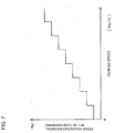
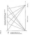
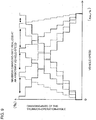
- such a configuration may be allowed that the changing-rate of the operation-angle of the trunnion shaft 21t with respect to the HST pedal stepping-on-quantity is made to get large corresponding to the vehicle-speed.
- the configuration is such that when the worker, at the time of starting-out, wants to slowly move the tractor, the operation-quantity of the trunnion shaft is made to be small at a time when the vehicle-speed is low, slow starting-out can be carried out without attention being paid to the stepping-on-quantity of the HST pedal, and motion and working becomes able to be safely carried out even inside a narrow warehouse, or at a farm field corner or the like.
- FIG. 7 is a diagram which shows the relation between the vehicle-speed and the changing-rate of the trunnion-operation-angle.
- the configuration is such that when the worker, at the time of starting-out, wants to slowly move the tractor, the operation-quantity of the trunnion shaft is made to be small at a time when the vehicle-speed is low, slow starting-out can be carried out without attention being paid to the stepping-on-quantity of the HST pedal, and motion and working becomes able to be safely carried out even inside a narrow warehouse, or at a farm field corner or the like. Moreover, even when the speed is fast, the speed setting up is easy since the changing-quantity at the time of slight adjustment becomes constant.
- FIG. 8 is a diagram which shows the relation between the vehicle-speed and the changing-rate of the trunnion-operation-angle.
- FIG. 9 is a diagram which shows the relation between the vehicle-speed and the changing-rate of the trunnion-operation-angle.
- oil-hydrostatic motor being the constant-quantity oil-hydrostatic motor 21m (refer to FIG. 4A ) where no swash plate is provided, but a second oil-hydrostatic type non-step transmission device 11b (a second HST 11b) of the present Second Embodiment has, as shown in FIG. 4B , a variable oil-hydrostatic motor 121m where a swash plate 121s is provided.
- the configuration is made to be such that two-stepped switching of the outputting of the variable oil-hydrostatic motor 121m is able to be carried out for the high speed and the low speed, which is said to be the two-stage switching of the variable oil-hydrostatic motor 121m which has the swash plate 121s.
- oil-hydrostatic pump 21p of the present Second Embodiment corresponds to one example of a speed-changing part of the present invention
- a Hi-Lo switching lever 210 of the present Second Embodiment corresponds to one example of a switching part of the present invention.
- Two-stage switching for the low speed side and the high speed side is performed with making rotary-motion of the swash plate 121s be carried out with a trunnion shaft 121t at the side of the variable oil-hydrostatic motor 121m, and the operation angle of the trunnion shaft 121t is switched by the stage switching valve 122.
- the Hi-Lo switching lever 210 which instructs switching of the stage switching valve 122 is arranged in the neighborhood of the lower part of the steering handle 7a (refer to FIG. 10 ).
- the mechanism which instructs switching of the stage switching valve 122 is made not to be a switch of a push type, but to be a switch of a lever type, the position of the lever can be easily checked at the time of manipulation.
- the Hi-Lo switching lever 210 is arranged in the neighborhood of the lower part of the steering handle 7a, switching manipulation is to be promptly and easily performed, speed-changing loss is small, and working efficiency improves. From the above, by this configuration, a sense of manipulation is good in comparison with a conventional one, and improvement of manipulability is contemplated.
- the stage switching valve 122 switches to the Hi if the Hi-Lo switching lever 210 is manipulated upward, and the stage switching valve 122 switches to the Lo if the Hi-Lo switching lever 210 is manipulated downward.
- the Hi-Lo switching lever 210 plays the role of instructing increase/decrease of the vehicle-speed in the auto-cruise mode. By means of this, the number of the switches is to be decreased.
- FIG. 10 is an enlarged perspective view in which the Hi-Lo switching lever 210 and the steering handle 7a are viewed from the side of the working seat 7, for showing the arrangement relation of the Hi-Lo switching lever 210 and the steering handle 7a.
- the memory 110 of the present Second Embodiment has, other than the functions which have been described in the above-mentioned First Embodiment, a function of memorizing the vehicle-speed.
- a memory restoring switch 220 (refer to FIG. 11 ) is provided which instructs whether or not to make the vehicle-speed of the traveling-vehicle-body shift to the vehicle-speed memorized in the memory 110.
- a controlling part 100' (refer to FIG. 11 ) of the present Second Embodiment has, other than the functions of the controlling part 100 which have been described in the above-mentioned First Embodiment, a function of accepting each of the outputtings from the Hi-Lo switching lever 210, the auto-cruise switch 7h, and the memory restoring switch 220, and also controls the action of the stage switching valve 122.
- FIG. 11 is an inputting-outputting block diagram which describes the controlling part 100' of the second tractor 200 of the present embodiment.
- the controlling part 100' (refer to FIG. 11 ) of the present Second Embodiment accepts, while the auto-cruise mode is in the ON state by the instruction from the auto-cruise switch 7h, the instruction of increase/decrease of the rotation number of the variable oil-hydrostatic motor 121m of the second HST 11b, which is carried out by the Hi-Lo switching lever 210, as an instruction of increase/decrease of the vehicle-speed in the auto-cruise mode.
- the controlling part 100' makes, on an occasion when the auto-cruise mode is switched from the ON state to the OFF state by the auto-cruise switch 7h, the vehicle-speed of the traveling-vehicle-body immediately before the manipulation of the switching be memorized in the memory 110 (refer to FIG. 11 ).
- the controlling part 100' makes, on an occasion when, after the auto-cruise mode is switched to the ON state by the auto-cruise switch 7h, with manipulation of the worker, a shifting instruction of the vehicle-speed is received from the memory restoring switch 220, the vehicle-speed of the traveling-vehicle-body shift to the vehicle-speed memorized in the memory 110.
- FIG. 12 is a flow diagram of the auto-cruise mode in the present embodiment.
- Step S20 As shown in FIG. 12 , if the auto-cruise switch 7h is turned ON by the worker, then the controlling part 100', moving on to Step S20 through Step S10, accepts from the HST pedal stepping-on-quantity detecting sensor 31 the stepping-on-quantity of the HST pedal 7b at the point in time when the controlling part 100' has accepted the ON signal from the auto-cruise switch 7h, in such a manner that traveling is carried out with the vehicle-speed in correspondence to the accepted stepping-on-quantity being maintained, sends an outputting signal to the proportional solenoid valve 22, and carries out controlling so that the rotary-motion-quantity of the trunnion shaft 21t of the oil-hydrostatic pump 21p of the second HST 11b (refer to FIG. 4B ) becomes constant (refer to Step S20).
- the controlling part 100' since the controlling part 100' accepts, as an instruction of increase/decrease of the vehicle-speed in the auto-cruise mode, the instruction by the Hi-Lo switching lever 210, then the controlling part 100', moving on to Step S40 through Step S30, in such a manner that the traveling is carried out with the vehicle-speed after the slight speed increase/decrease manipulation being maintained, sends an outputting signal to the stage switching valve 122.
- the controlling part 100' in such a manner that rotary-motion of the trunnion shaft 121t at the side of the variable oil-hydrostatic motor 121m is made to be carried out in a direction for which the vehicle-speed slightly increases, issues an order to the stage switching valve 122, moving on to Step S50.
- Step S30 the vehicle-speed at the point in time when the ON signal from the auto-cruise switch 7h has been accepted is being maintained (refer to Step S45), moving on to Step S50.
- Step S50 in case the controlling part 100', in Step S50, does not accept an ON signal from the memory restoring switch 220, moving on to Step S60, the controlling part 100' judges whether or not the auto-cruise switch 7h has been switched from ON to OFF and, when it is judged that the auto-cruise switch 7h has been switched to OFF, moving on to Step S70, makes the vehicle-speed immediately before the auto-cruise switch 7h is switched from ON to OFF be memorized in the memory 110.
- Step S60 when in Step S60 it is judged that the auto-cruise switch 7h has not been switched from ON to OFF, returns to the state immediately before Step S30.
- Step S80 if the memory restoring switch 220 is judged to have been turned ON.
- the controlling part 100' judges whether or not the vehicle-speed immediately before the auto-cruise switch 7h is switched from ON to OFF is memorized in the memory 110, in a case where it is judged that the vehicle-speed immediately before the auto-cruise switch 7h is switched from ON to OFF is memorized, makes the vehicle-speed alter to the vehicle-speed immediately before the auto-cruise switch 7h is switched from ON to OFF (Step S90) and, afterward, returns to the state immediately before Step S30.
- Step S80 judging whether or not the vehicle-speed immediately before the auto-cruise switch 7h is switched from ON to OFF is memorized in the memory 110, it is judged that the vehicle-speed immediately before the auto-cruise switch 7h is switched from ON to OFF is not memorized, the controlling part 100' returns to the state immediately before Step S50.
- the Hi-Lo switching lever 210 plays the role of instructing increase/decrease of the vehicle-speed in the auto-cruise mode but, not being limited to this, for example, such a configuration may be allowed that switching between the "Hi” and the "Lo" of the vehicle-speed cannot be carried out even if, during the auto-cruise mode, the Hi-Lo switching lever 210 is manipulated in the up-and-down direction.
- a tractor which is one example of a working vehicle of the present invention may be a third tractor which has the configurations and functions newly described in the above-mentioned Second Embodiment but does not have such configurations and functions or the like, which is a part of the configurations and functions described in the above-mentioned First Embodiment, that traveling-controlling suitable for various working modes becomes able to be carried out with storing beforehand corresponding to various working modes the relation between the HST pedal stepping-on-quantity and the trunnion operation-quantity, for example.
- tractors which are for agriculture
- a working vehicle of the present invention may be a tractor which is for architecture, or for transport or, alternatively, not being limited to a tractor, for example, may be a different working vehicle.
- the HST pedal 7b of the above-mentioned embodiment corresponds to one example of a speed-changing instructor of the present invention
- the HST pedal stepping-on-quantity detecting sensor 31 of the present embodiment corresponds to one example of a speed-changing manipulation-quantity detecting sensor of the present invention.
- a working vehicle of the present invention is useful for a working vehicle such as a tractor or the like which is for agriculture, for architecture, for transport, or the like since a working vehicle for which the number of the switches is to be decreased can be furnished.
Landscapes
- Engineering & Computer Science (AREA)
- Mechanical Engineering (AREA)
- Transportation (AREA)
- General Engineering & Computer Science (AREA)
- Automation & Control Theory (AREA)
- Chemical & Material Sciences (AREA)
- Combustion & Propulsion (AREA)
- Control Of Fluid Gearings (AREA)
- Control Of Transmission Device (AREA)
- Controls For Constant Speed Travelling (AREA)
Claims (4)
- Véhicule utilitaire (200), comprenant :un moteur (4) qui est chargé sur un châssis de véhicule roulant ;un système de transmission ;une partie de changement de vitesses (21p) qui effectue des changements de vitesses et qui délivre une force motrice du moteur (4) ;un levier de changement de vitesses (7b) manipulé par l'opérateur, qui demande le changement de vitesses au sein de la partie de changement de vitesses (21p) ;un détecteur de quantité de manipulation de changement de vitesses (31) qui détecte une quantité de manipulation, par l'opérateur, du levier de changement de vitesses (7b) ;une partie de commande (100') qui contrôle la partie de changement de vitesses (21p) sur la base de la détection du détecteur de quantité de manipulation de changement de vitesses (31) ;une partie de commutation (210), manipulée par l'opérateur, qui provoque l'augmentation/la diminution de la vitesse de sortie du système de transmission après le changement de vitesses au sein de la partie de changement de vitesses (21p) ; etun bouton de régulation automatique (7h) qui déclenche/arrête un mode de régulation automatique destiné à maintenir la vitesse du châssis de véhicule roulant constante,caractérisé en ce quela partie de contrôle (100') (i) accepte, pendant que le mode de régulation automatique est OFF, l'instruction de la partie de commutation (210) qui est destinée à augmenter/diminuer la vitesse de sortie du système de transmission après le changement de vitesses correspondant au levier de changement de vitesses (7b), et (ii) accepte, pendant que le mode de régulation automatique est ON sur instruction du bouton de régulation automatique (7h), l'instruction de la partie de commutation (210) qui est destinée à augmenter/diminuer légèrement la vitesse constante du véhicule en mode de régulation automatique.
- Véhicule utilitaire (200) selon la revendication 1, dans lequel
la partie de commutation (210) est un levier de commutation qui est prévu sur une périphérie d'une poignée de commande (7a) prévue dans le châssis de véhicule roulant. - Véhicule utilitaire (200) selon la revendication 1 ou 2, comprenant :une partie de mémoire (110) qui mémorise la vitesse du véhicule ; etun bouton de restauration de mémoire (220) qui demande si la vitesse du véhicule roulant doit passer ou non à la vitesse mémorisée dans la partie de mémoire (110),dans lequel la partie de contrôle (100') mémorise dans la partie de mémoire (110), lorsque le mode de régulation automatique passe d'un état ON à un état OFF à l'aide du bouton de régulation automatique (7h), la vitesse du châssis de véhicule roulant immédiatement avant la manipulation de la partie de commutation, etdans lequel la partie de contrôle (100') applique, par la suite, lorsque, une fois que le mode de régulation automatique est passé à l'état ON à l'aide du bouton de régulation automatique (7h), l'instruction de changement de vitesse du véhicule est reçue de la part du bouton de restauration de mémoire (220), le passage de la vitesse du châssis de véhicule roulant à la vitesse mémorisée dans la partie de mémoire (110).
- Véhicule utilitaire (200) selon la revendication 1, dans lequel
la partie de changement de vitesse (21p) est une pompe hydrostatique à huile (21p) qui est une partie d'admission d'un dispositif de transmission linéaire hydrostatique à huile (11b),
la partie de commutation (210) demande l'augmentation/la diminution d'un nombre de rotations d'un moteur hydrostatique à huile variable (121m) qui est une partie de sortie du dispositif de transmission linéaire hydrostatique à huile (11b),
le levier de changement de vitesses (7b) est une pédale, et
la partie de contrôle (100') qui contrôle le moteur hydrostatique à huile variable (121m) sur la base de l'instruction de la partie de commutation (210) (i) accepte, pendant que le mode de régulation automatique est OFF, l'instruction de la partie de commutation (210), non pas comme instruction en mode de régulation automatique, mais comme instruction de commutation en deux étapes d'un nombre de rotations du moteur hydrostatique à huile variable afin d'augmenter/de diminuer la vitesse du moteur hydrostatique à huile variable après le changement de vitesse correspondant à l'actionnement de la pédale en guise de levier de changement de vitesses (7b), et (ii) accepte, pendant que le mode de régulation automatique est ON par l'instruction du bouton de régulation automatique (7h), l'instruction de la partie de commutation (210) comme une instruction de légère augmentation/diminution de la vitesse constante du véhicule en mode de régulation automatique, tout en effectuant un contrôle de sorte qu'une quantité de mouvement de rotation d'un arbre de tourillon (21t) de la pompe hydrostatique à huile (21p) devienne constante.
Applications Claiming Priority (1)
| Application Number | Priority Date | Filing Date | Title |
|---|---|---|---|
| JP2014108123A JP6221940B2 (ja) | 2014-05-26 | 2014-05-26 | 作業車両 |
Publications (2)
| Publication Number | Publication Date |
|---|---|
| EP2949971A1 EP2949971A1 (fr) | 2015-12-02 |
| EP2949971B1 true EP2949971B1 (fr) | 2020-02-12 |
Family
ID=53365755
Family Applications (1)
| Application Number | Title | Priority Date | Filing Date |
|---|---|---|---|
| EP15168916.3A Active EP2949971B1 (fr) | 2014-05-26 | 2015-05-22 | Véhicule de travail |
Country Status (4)
| Country | Link |
|---|---|
| EP (1) | EP2949971B1 (fr) |
| JP (1) | JP6221940B2 (fr) |
| AU (1) | AU2015202774B2 (fr) |
| NZ (1) | NZ708393A (fr) |
Families Citing this family (2)
| Publication number | Priority date | Publication date | Assignee | Title |
|---|---|---|---|---|
| CN108119242B (zh) * | 2017-12-11 | 2020-05-22 | 中国第一汽车股份有限公司 | 一种基于按键式开关的电子手油门系统及其控制方法 |
| US12338606B2 (en) | 2021-09-02 | 2025-06-24 | Caterpillar Inc. | Inching systems and methods |
Family Cites Families (9)
| Publication number | Priority date | Publication date | Assignee | Title |
|---|---|---|---|---|
| JPH0648216A (ja) * | 1992-07-29 | 1994-02-22 | Toyota Motor Corp | 定速走行装置付車両の自動変速機の制御装置 |
| AT4125U1 (de) | 1999-04-28 | 2001-02-26 | Case Steyr Landmaschinentechni | Vorrichtung und verfahren zum verändern der ist-geschwindigkeit eines arbeitsfahrzeuges mit stufenlosgetriebe und tempomatfunktion |
| US6655233B2 (en) * | 2001-07-13 | 2003-12-02 | Deere & Company | Speed control for a utility vehicle |
| US7641588B2 (en) * | 2007-01-31 | 2010-01-05 | Caterpillar Inc. | CVT system having discrete selectable speed ranges |
| JP5228538B2 (ja) * | 2008-02-29 | 2013-07-03 | 井関農機株式会社 | 作業車 |
| JP5933296B2 (ja) * | 2011-07-29 | 2016-06-08 | 株式会社クボタ | 車両用変速制御システム |
| JP2013170609A (ja) * | 2012-02-20 | 2013-09-02 | Iseki & Co Ltd | 作業車両 |
| JP5660071B2 (ja) * | 2012-03-29 | 2015-01-28 | 井関農機株式会社 | 作業車両 |
| JP6070632B2 (ja) * | 2014-05-26 | 2017-02-01 | 井関農機株式会社 | 作業車両 |
-
2014
- 2014-05-26 JP JP2014108123A patent/JP6221940B2/ja not_active Expired - Fee Related
-
2015
- 2015-05-22 AU AU2015202774A patent/AU2015202774B2/en not_active Ceased
- 2015-05-22 NZ NZ708393A patent/NZ708393A/en not_active IP Right Cessation
- 2015-05-22 EP EP15168916.3A patent/EP2949971B1/fr active Active
Non-Patent Citations (1)
| Title |
|---|
| None * |
Also Published As
| Publication number | Publication date |
|---|---|
| AU2015202774B2 (en) | 2016-06-30 |
| NZ708393A (en) | 2016-07-29 |
| AU2015202774A1 (en) | 2015-12-10 |
| JP2015224656A (ja) | 2015-12-14 |
| JP6221940B2 (ja) | 2017-11-01 |
| EP2949971A1 (fr) | 2015-12-02 |
Similar Documents
| Publication | Publication Date | Title |
|---|---|---|
| EP3744603B1 (fr) | Véhicule de travail | |
| US9944292B2 (en) | Working vehicle | |
| JP2019004792A (ja) | 作業場の走行管理システム | |
| EP2949971B1 (fr) | Véhicule de travail | |
| JP6548609B2 (ja) | 作業車 | |
| JP4044710B2 (ja) | 作業車両 | |
| US7503232B2 (en) | Working vehicle | |
| JP2005119466A (ja) | 作業車両の走行変速装置 | |
| JP2020000140A (ja) | 作業車両 | |
| JP2020000141A (ja) | 作業車両 | |
| JP6070632B2 (ja) | 作業車両 | |
| JP2006125535A (ja) | 移動車両のオートクルーズ装置 | |
| US11801840B2 (en) | Work vehicle, control method, and recording medium | |
| JP6102838B2 (ja) | 作業車両 | |
| JP6484977B2 (ja) | 作業車両 | |
| JP4479325B2 (ja) | トラクタのpto制御装置 | |
| JP6137500B2 (ja) | 作業車両 | |
| JP6350642B2 (ja) | 作業車輌 | |
| JP7156186B2 (ja) | 作業車両 | |
| JP5451657B2 (ja) | 車両用エンジン制御システム | |
| JP2022010724A (ja) | 作業機 | |
| JP7482766B2 (ja) | 作業車 | |
| JP7388515B2 (ja) | 作業車両 | |
| JP7259647B2 (ja) | 作業車両 | |
| JP4140613B2 (ja) | 作業車両 |
Legal Events
| Date | Code | Title | Description |
|---|---|---|---|
| 17P | Request for examination filed |
Effective date: 20150527 |
|
| AK | Designated contracting states |
Kind code of ref document: A1 Designated state(s): AL AT BE BG CH CY CZ DE DK EE ES FI FR GB GR HR HU IE IS IT LI LT LU LV MC MK MT NL NO PL PT RO RS SE SI SK SM TR |
|
| AX | Request for extension of the european patent |
Extension state: BA ME |
|
| PUAI | Public reference made under article 153(3) epc to a published international application that has entered the european phase |
Free format text: ORIGINAL CODE: 0009012 |
|
| STAA | Information on the status of an ep patent application or granted ep patent |
Free format text: STATUS: EXAMINATION IS IN PROGRESS |
|
| 17Q | First examination report despatched |
Effective date: 20170710 |
|
| RIC1 | Information provided on ipc code assigned before grant |
Ipc: B60W 30/14 20060101ALI20181127BHEP Ipc: B60K 31/04 20060101ALI20181127BHEP Ipc: F16H 61/47 20100101AFI20181127BHEP |
|
| GRAP | Despatch of communication of intention to grant a patent |
Free format text: ORIGINAL CODE: EPIDOSNIGR1 |
|
| STAA | Information on the status of an ep patent application or granted ep patent |
Free format text: STATUS: GRANT OF PATENT IS INTENDED |
|
| INTG | Intention to grant announced |
Effective date: 20190913 |
|
| GRAS | Grant fee paid |
Free format text: ORIGINAL CODE: EPIDOSNIGR3 |
|
| GRAA | (expected) grant |
Free format text: ORIGINAL CODE: 0009210 |
|
| STAA | Information on the status of an ep patent application or granted ep patent |
Free format text: STATUS: THE PATENT HAS BEEN GRANTED |
|
| AK | Designated contracting states |
Kind code of ref document: B1 Designated state(s): AL AT BE BG CH CY CZ DE DK EE ES FI FR GB GR HR HU IE IS IT LI LT LU LV MC MK MT NL NO PL PT RO RS SE SI SK SM TR |
|
| REG | Reference to a national code |
Ref country code: GB Ref legal event code: FG4D |
|
| REG | Reference to a national code |
Ref country code: CH Ref legal event code: EP |
|
| REG | Reference to a national code |
Ref country code: AT Ref legal event code: REF Ref document number: 1232527 Country of ref document: AT Kind code of ref document: T Effective date: 20200215 |
|
| REG | Reference to a national code |
Ref country code: IE Ref legal event code: FG4D |
|
| REG | Reference to a national code |
Ref country code: DE Ref legal event code: R096 Ref document number: 602015046660 Country of ref document: DE |
|
| PG25 | Lapsed in a contracting state [announced via postgrant information from national office to epo] |
Ref country code: FI Free format text: LAPSE BECAUSE OF FAILURE TO SUBMIT A TRANSLATION OF THE DESCRIPTION OR TO PAY THE FEE WITHIN THE PRESCRIBED TIME-LIMIT Effective date: 20200212 Ref country code: NO Free format text: LAPSE BECAUSE OF FAILURE TO SUBMIT A TRANSLATION OF THE DESCRIPTION OR TO PAY THE FEE WITHIN THE PRESCRIBED TIME-LIMIT Effective date: 20200512 Ref country code: RS Free format text: LAPSE BECAUSE OF FAILURE TO SUBMIT A TRANSLATION OF THE DESCRIPTION OR TO PAY THE FEE WITHIN THE PRESCRIBED TIME-LIMIT Effective date: 20200212 |
|
| REG | Reference to a national code |
Ref country code: LT Ref legal event code: MG4D |
|
| REG | Reference to a national code |
Ref country code: NL Ref legal event code: MP Effective date: 20200212 |
|
| PG25 | Lapsed in a contracting state [announced via postgrant information from national office to epo] |
Ref country code: BG Free format text: LAPSE BECAUSE OF FAILURE TO SUBMIT A TRANSLATION OF THE DESCRIPTION OR TO PAY THE FEE WITHIN THE PRESCRIBED TIME-LIMIT Effective date: 20200512 Ref country code: GR Free format text: LAPSE BECAUSE OF FAILURE TO SUBMIT A TRANSLATION OF THE DESCRIPTION OR TO PAY THE FEE WITHIN THE PRESCRIBED TIME-LIMIT Effective date: 20200513 Ref country code: HR Free format text: LAPSE BECAUSE OF FAILURE TO SUBMIT A TRANSLATION OF THE DESCRIPTION OR TO PAY THE FEE WITHIN THE PRESCRIBED TIME-LIMIT Effective date: 20200212 Ref country code: IS Free format text: LAPSE BECAUSE OF FAILURE TO SUBMIT A TRANSLATION OF THE DESCRIPTION OR TO PAY THE FEE WITHIN THE PRESCRIBED TIME-LIMIT Effective date: 20200612 Ref country code: SE Free format text: LAPSE BECAUSE OF FAILURE TO SUBMIT A TRANSLATION OF THE DESCRIPTION OR TO PAY THE FEE WITHIN THE PRESCRIBED TIME-LIMIT Effective date: 20200212 Ref country code: LV Free format text: LAPSE BECAUSE OF FAILURE TO SUBMIT A TRANSLATION OF THE DESCRIPTION OR TO PAY THE FEE WITHIN THE PRESCRIBED TIME-LIMIT Effective date: 20200212 |
|
| PG25 | Lapsed in a contracting state [announced via postgrant information from national office to epo] |
Ref country code: NL Free format text: LAPSE BECAUSE OF FAILURE TO SUBMIT A TRANSLATION OF THE DESCRIPTION OR TO PAY THE FEE WITHIN THE PRESCRIBED TIME-LIMIT Effective date: 20200212 |
|
| PG25 | Lapsed in a contracting state [announced via postgrant information from national office to epo] |
Ref country code: CZ Free format text: LAPSE BECAUSE OF FAILURE TO SUBMIT A TRANSLATION OF THE DESCRIPTION OR TO PAY THE FEE WITHIN THE PRESCRIBED TIME-LIMIT Effective date: 20200212 Ref country code: ES Free format text: LAPSE BECAUSE OF FAILURE TO SUBMIT A TRANSLATION OF THE DESCRIPTION OR TO PAY THE FEE WITHIN THE PRESCRIBED TIME-LIMIT Effective date: 20200212 Ref country code: RO Free format text: LAPSE BECAUSE OF FAILURE TO SUBMIT A TRANSLATION OF THE DESCRIPTION OR TO PAY THE FEE WITHIN THE PRESCRIBED TIME-LIMIT Effective date: 20200212 Ref country code: EE Free format text: LAPSE BECAUSE OF FAILURE TO SUBMIT A TRANSLATION OF THE DESCRIPTION OR TO PAY THE FEE WITHIN THE PRESCRIBED TIME-LIMIT Effective date: 20200212 Ref country code: SM Free format text: LAPSE BECAUSE OF FAILURE TO SUBMIT A TRANSLATION OF THE DESCRIPTION OR TO PAY THE FEE WITHIN THE PRESCRIBED TIME-LIMIT Effective date: 20200212 Ref country code: DK Free format text: LAPSE BECAUSE OF FAILURE TO SUBMIT A TRANSLATION OF THE DESCRIPTION OR TO PAY THE FEE WITHIN THE PRESCRIBED TIME-LIMIT Effective date: 20200212 Ref country code: LT Free format text: LAPSE BECAUSE OF FAILURE TO SUBMIT A TRANSLATION OF THE DESCRIPTION OR TO PAY THE FEE WITHIN THE PRESCRIBED TIME-LIMIT Effective date: 20200212 Ref country code: PT Free format text: LAPSE BECAUSE OF FAILURE TO SUBMIT A TRANSLATION OF THE DESCRIPTION OR TO PAY THE FEE WITHIN THE PRESCRIBED TIME-LIMIT Effective date: 20200705 Ref country code: SK Free format text: LAPSE BECAUSE OF FAILURE TO SUBMIT A TRANSLATION OF THE DESCRIPTION OR TO PAY THE FEE WITHIN THE PRESCRIBED TIME-LIMIT Effective date: 20200212 |
|
| REG | Reference to a national code |
Ref country code: DE Ref legal event code: R097 Ref document number: 602015046660 Country of ref document: DE |
|
| REG | Reference to a national code |
Ref country code: AT Ref legal event code: MK05 Ref document number: 1232527 Country of ref document: AT Kind code of ref document: T Effective date: 20200212 |
|
| PLBE | No opposition filed within time limit |
Free format text: ORIGINAL CODE: 0009261 |
|
| STAA | Information on the status of an ep patent application or granted ep patent |
Free format text: STATUS: NO OPPOSITION FILED WITHIN TIME LIMIT |
|
| 26N | No opposition filed |
Effective date: 20201113 |
|
| PG25 | Lapsed in a contracting state [announced via postgrant information from national office to epo] |
Ref country code: AT Free format text: LAPSE BECAUSE OF FAILURE TO SUBMIT A TRANSLATION OF THE DESCRIPTION OR TO PAY THE FEE WITHIN THE PRESCRIBED TIME-LIMIT Effective date: 20200212 Ref country code: IT Free format text: LAPSE BECAUSE OF FAILURE TO SUBMIT A TRANSLATION OF THE DESCRIPTION OR TO PAY THE FEE WITHIN THE PRESCRIBED TIME-LIMIT Effective date: 20200212 Ref country code: MC Free format text: LAPSE BECAUSE OF FAILURE TO SUBMIT A TRANSLATION OF THE DESCRIPTION OR TO PAY THE FEE WITHIN THE PRESCRIBED TIME-LIMIT Effective date: 20200212 Ref country code: CH Free format text: LAPSE BECAUSE OF NON-PAYMENT OF DUE FEES Effective date: 20200531 Ref country code: LI Free format text: LAPSE BECAUSE OF NON-PAYMENT OF DUE FEES Effective date: 20200531 |
|
| PG25 | Lapsed in a contracting state [announced via postgrant information from national office to epo] |
Ref country code: PL Free format text: LAPSE BECAUSE OF FAILURE TO SUBMIT A TRANSLATION OF THE DESCRIPTION OR TO PAY THE FEE WITHIN THE PRESCRIBED TIME-LIMIT Effective date: 20200212 Ref country code: SI Free format text: LAPSE BECAUSE OF FAILURE TO SUBMIT A TRANSLATION OF THE DESCRIPTION OR TO PAY THE FEE WITHIN THE PRESCRIBED TIME-LIMIT Effective date: 20200212 |
|
| PG25 | Lapsed in a contracting state [announced via postgrant information from national office to epo] |
Ref country code: LU Free format text: LAPSE BECAUSE OF NON-PAYMENT OF DUE FEES Effective date: 20200522 |
|
| PG25 | Lapsed in a contracting state [announced via postgrant information from national office to epo] |
Ref country code: IE Free format text: LAPSE BECAUSE OF NON-PAYMENT OF DUE FEES Effective date: 20200522 |
|
| PG25 | Lapsed in a contracting state [announced via postgrant information from national office to epo] |
Ref country code: TR Free format text: LAPSE BECAUSE OF FAILURE TO SUBMIT A TRANSLATION OF THE DESCRIPTION OR TO PAY THE FEE WITHIN THE PRESCRIBED TIME-LIMIT Effective date: 20200212 Ref country code: MT Free format text: LAPSE BECAUSE OF FAILURE TO SUBMIT A TRANSLATION OF THE DESCRIPTION OR TO PAY THE FEE WITHIN THE PRESCRIBED TIME-LIMIT Effective date: 20200212 Ref country code: CY Free format text: LAPSE BECAUSE OF FAILURE TO SUBMIT A TRANSLATION OF THE DESCRIPTION OR TO PAY THE FEE WITHIN THE PRESCRIBED TIME-LIMIT Effective date: 20200212 |
|
| PG25 | Lapsed in a contracting state [announced via postgrant information from national office to epo] |
Ref country code: MK Free format text: LAPSE BECAUSE OF FAILURE TO SUBMIT A TRANSLATION OF THE DESCRIPTION OR TO PAY THE FEE WITHIN THE PRESCRIBED TIME-LIMIT Effective date: 20200212 Ref country code: AL Free format text: LAPSE BECAUSE OF FAILURE TO SUBMIT A TRANSLATION OF THE DESCRIPTION OR TO PAY THE FEE WITHIN THE PRESCRIBED TIME-LIMIT Effective date: 20200212 |
|
| PGFP | Annual fee paid to national office [announced via postgrant information from national office to epo] |
Ref country code: BE Payment date: 20220502 Year of fee payment: 8 |
|
| REG | Reference to a national code |
Ref country code: FR Ref legal event code: PLFP Year of fee payment: 9 |
|
| REG | Reference to a national code |
Ref country code: BE Ref legal event code: MM Effective date: 20230531 |
|
| PG25 | Lapsed in a contracting state [announced via postgrant information from national office to epo] |
Ref country code: BE Free format text: LAPSE BECAUSE OF NON-PAYMENT OF DUE FEES Effective date: 20230531 |
|
| PGFP | Annual fee paid to national office [announced via postgrant information from national office to epo] |
Ref country code: DE Payment date: 20250402 Year of fee payment: 11 |
|
| PGFP | Annual fee paid to national office [announced via postgrant information from national office to epo] |
Ref country code: GB Payment date: 20250401 Year of fee payment: 11 |
|
| PGFP | Annual fee paid to national office [announced via postgrant information from national office to epo] |
Ref country code: FR Payment date: 20250401 Year of fee payment: 11 |