EP2949994A1 - Appareil de combustion - Google Patents
Appareil de combustion Download PDFInfo
- Publication number
- EP2949994A1 EP2949994A1 EP14742810.6A EP14742810A EP2949994A1 EP 2949994 A1 EP2949994 A1 EP 2949994A1 EP 14742810 A EP14742810 A EP 14742810A EP 2949994 A1 EP2949994 A1 EP 2949994A1
- Authority
- EP
- European Patent Office
- Prior art keywords
- gas
- passage
- opening
- closing member
- combustion
- Prior art date
- Legal status (The legal status is an assumption and is not a legal conclusion. Google has not performed a legal analysis and makes no representation as to the accuracy of the status listed.)
- Withdrawn
Links
Images




Classifications
-
- F—MECHANICAL ENGINEERING; LIGHTING; HEATING; WEAPONS; BLASTING
- F23—COMBUSTION APPARATUS; COMBUSTION PROCESSES
- F23C—METHODS OR APPARATUS FOR COMBUSTION USING FLUID FUEL OR SOLID FUEL SUSPENDED IN A CARRIER GAS OR AIR
- F23C9/00—Combustion apparatus characterised by arrangements for returning combustion products or flue gases to the combustion chamber
- F23C9/08—Combustion apparatus characterised by arrangements for returning combustion products or flue gases to the combustion chamber for reducing temperature in combustion chamber, e.g. for protecting walls of combustion chamber
-
- G—PHYSICS
- G09—EDUCATION; CRYPTOGRAPHY; DISPLAY; ADVERTISING; SEALS
- G09B—EDUCATIONAL OR DEMONSTRATION APPLIANCES; APPLIANCES FOR TEACHING, OR COMMUNICATING WITH, THE BLIND, DEAF OR MUTE; MODELS; PLANETARIA; GLOBES; MAPS; DIAGRAMS
- G09B23/00—Models for scientific, medical, or mathematical purposes, e.g. full-sized devices for demonstration purposes
- G09B23/40—Models for scientific, medical, or mathematical purposes, e.g. full-sized devices for demonstration purposes for geology
-
- F—MECHANICAL ENGINEERING; LIGHTING; HEATING; WEAPONS; BLASTING
- F23—COMBUSTION APPARATUS; COMBUSTION PROCESSES
- F23C—METHODS OR APPARATUS FOR COMBUSTION USING FLUID FUEL OR SOLID FUEL SUSPENDED IN A CARRIER GAS OR AIR
- F23C9/00—Combustion apparatus characterised by arrangements for returning combustion products or flue gases to the combustion chamber
-
- F—MECHANICAL ENGINEERING; LIGHTING; HEATING; WEAPONS; BLASTING
- F23—COMBUSTION APPARATUS; COMBUSTION PROCESSES
- F23C—METHODS OR APPARATUS FOR COMBUSTION USING FLUID FUEL OR SOLID FUEL SUSPENDED IN A CARRIER GAS OR AIR
- F23C7/00—Combustion apparatus characterised by arrangements for air supply
- F23C7/02—Disposition of air supply not passing through burner
- F23C7/06—Disposition of air supply not passing through burner for heating the incoming air
-
- F—MECHANICAL ENGINEERING; LIGHTING; HEATING; WEAPONS; BLASTING
- F23—COMBUSTION APPARATUS; COMBUSTION PROCESSES
- F23D—BURNERS
- F23D14/00—Burners for combustion of a gas, e.g. of a gas stored under pressure as a liquid
- F23D14/02—Premix gas burners, i.e. in which gaseous fuel is mixed with combustion air upstream of the combustion zone
-
- F—MECHANICAL ENGINEERING; LIGHTING; HEATING; WEAPONS; BLASTING
- F23—COMBUSTION APPARATUS; COMBUSTION PROCESSES
- F23D—BURNERS
- F23D14/00—Burners for combustion of a gas, e.g. of a gas stored under pressure as a liquid
- F23D14/34—Burners specially adapted for use with means for pressurising the gaseous fuel or the combustion air
- F23D14/36—Burners specially adapted for use with means for pressurising the gaseous fuel or the combustion air in which the compressor and burner form a single unit
-
- F—MECHANICAL ENGINEERING; LIGHTING; HEATING; WEAPONS; BLASTING
- F23—COMBUSTION APPARATUS; COMBUSTION PROCESSES
- F23D—BURNERS
- F23D14/00—Burners for combustion of a gas, e.g. of a gas stored under pressure as a liquid
- F23D14/46—Details
- F23D14/62—Mixing devices; Mixing tubes
-
- F—MECHANICAL ENGINEERING; LIGHTING; HEATING; WEAPONS; BLASTING
- F23—COMBUSTION APPARATUS; COMBUSTION PROCESSES
- F23D—BURNERS
- F23D14/00—Burners for combustion of a gas, e.g. of a gas stored under pressure as a liquid
- F23D14/46—Details
- F23D14/66—Preheating the combustion air or gas
-
- G—PHYSICS
- G09—EDUCATION; CRYPTOGRAPHY; DISPLAY; ADVERTISING; SEALS
- G09B—EDUCATIONAL OR DEMONSTRATION APPLIANCES; APPLIANCES FOR TEACHING, OR COMMUNICATING WITH, THE BLIND, DEAF OR MUTE; MODELS; PLANETARIA; GLOBES; MAPS; DIAGRAMS
- G09B19/00—Teaching not covered by other main groups of this subclass
- G09B19/0061—Geography
-
- G—PHYSICS
- G09—EDUCATION; CRYPTOGRAPHY; DISPLAY; ADVERTISING; SEALS
- G09B—EDUCATIONAL OR DEMONSTRATION APPLIANCES; APPLIANCES FOR TEACHING, OR COMMUNICATING WITH, THE BLIND, DEAF OR MUTE; MODELS; PLANETARIA; GLOBES; MAPS; DIAGRAMS
- G09B25/00—Models for purposes not provided for in G09B23/00, e.g. full-sized devices for demonstration purposes
- G09B25/08—Models for purposes not provided for in G09B23/00, e.g. full-sized devices for demonstration purposes of scenic effects, e.g. trees, rocks, water surfaces
-
- F—MECHANICAL ENGINEERING; LIGHTING; HEATING; WEAPONS; BLASTING
- F23—COMBUSTION APPARATUS; COMBUSTION PROCESSES
- F23C—METHODS OR APPARATUS FOR COMBUSTION USING FLUID FUEL OR SOLID FUEL SUSPENDED IN A CARRIER GAS OR AIR
- F23C2202/00—Fluegas recirculation
- F23C2202/10—Premixing fluegas with fuel and combustion air
-
- F—MECHANICAL ENGINEERING; LIGHTING; HEATING; WEAPONS; BLASTING
- F23—COMBUSTION APPARATUS; COMBUSTION PROCESSES
- F23C—METHODS OR APPARATUS FOR COMBUSTION USING FLUID FUEL OR SOLID FUEL SUSPENDED IN A CARRIER GAS OR AIR
- F23C2900/00—Special features of, or arrangements for combustion apparatus using fluid fuels or solid fuels suspended in air; Combustion processes therefor
- F23C2900/09002—Specific devices inducing or forcing flue gas recirculation
-
- F—MECHANICAL ENGINEERING; LIGHTING; HEATING; WEAPONS; BLASTING
- F23—COMBUSTION APPARATUS; COMBUSTION PROCESSES
- F23D—BURNERS
- F23D2203/00—Gaseous fuel burners
- F23D2203/007—Mixing tubes, air supply regulation
-
- F—MECHANICAL ENGINEERING; LIGHTING; HEATING; WEAPONS; BLASTING
- F23—COMBUSTION APPARATUS; COMBUSTION PROCESSES
- F23D—BURNERS
- F23D2206/00—Burners for specific applications
-
- F—MECHANICAL ENGINEERING; LIGHTING; HEATING; WEAPONS; BLASTING
- F23—COMBUSTION APPARATUS; COMBUSTION PROCESSES
- F23D—BURNERS
- F23D2209/00—Safety arrangements
-
- F—MECHANICAL ENGINEERING; LIGHTING; HEATING; WEAPONS; BLASTING
- F23—COMBUSTION APPARATUS; COMBUSTION PROCESSES
- F23N—REGULATING OR CONTROLLING COMBUSTION
- F23N2221/00—Pretreatment or prehandling
- F23N2221/12—Recycling exhaust gases
-
- F—MECHANICAL ENGINEERING; LIGHTING; HEATING; WEAPONS; BLASTING
- F24—HEATING; RANGES; VENTILATING
- F24H—FLUID HEATERS, e.g. WATER OR AIR HEATERS, HAVING HEAT-GENERATING MEANS, e.g. HEAT PUMPS, IN GENERAL
- F24H1/00—Water heaters, e.g. boilers, continuous-flow heaters or water-storage heaters
- F24H1/22—Water heaters other than continuous-flow or water-storage heaters, e.g. water heaters for central heating
-
- Y—GENERAL TAGGING OF NEW TECHNOLOGICAL DEVELOPMENTS; GENERAL TAGGING OF CROSS-SECTIONAL TECHNOLOGIES SPANNING OVER SEVERAL SECTIONS OF THE IPC; TECHNICAL SUBJECTS COVERED BY FORMER USPC CROSS-REFERENCE ART COLLECTIONS [XRACs] AND DIGESTS
- Y02—TECHNOLOGIES OR APPLICATIONS FOR MITIGATION OR ADAPTATION AGAINST CLIMATE CHANGE
- Y02E—REDUCTION OF GREENHOUSE GAS [GHG] EMISSIONS, RELATED TO ENERGY GENERATION, TRANSMISSION OR DISTRIBUTION
- Y02E20/00—Combustion technologies with mitigation potential
- Y02E20/34—Indirect CO2mitigation, i.e. by acting on non CO2directly related matters of the process, e.g. pre-heating or heat recovery
Definitions
- the present invention relates to a combustion apparatus, more particularly, to a combustion apparatus in which a portion of an exhaust gas recirculates to an air intake side by using a differential pressure due to a venturi structure of the combustion apparatus to reduce a flame temperature, thereby reducing an emission amount of nitrogen oxide (NOx), and also, the exhaust gas recirculates to the air intake side in proportional to supply amounts of fuel and air according to a set load to maintain a uniform air-fuel ratio over an entire load area from a high power load to a low power load, thereby stably performing combustion.
- a portion of an exhaust gas recirculates to an air intake side by using a differential pressure due to a venturi structure of the combustion apparatus to reduce a flame temperature, thereby reducing an emission amount of nitrogen oxide (NOx)
- NOx nitrogen oxide
- combustion apparatuses are disposed in heating apparatuses in which water is heated by using combustion heat generated while fuel is burnt, and the heated water circulates along a tube to provide heating an indoor space or hot water.
- a general combustion apparatus includes a blower 10 supplying air, a gas supply part 20 for supplying a combustion gas by adjustment of a valve 22 through a gas supply tube 21 connected to one side of the blower 10, a burner 20 for burning a mixed-gas in which the air is mixed with the gas, a combustion chamber 40 in which the mixed-gas is burnt by ignition of the burner 30, a heat exchanger 50 for heating water supplied through a heating water supply tube 62 after being introduced through a heating water return tube 61 to circulate in the combustion apparatus, by using the combustion heat of the combustion chamber 40, and a duct 70 through which an exhaust gas passing through the heat exchanger 50 is discharged.
- a turn-down ratio (TDR) of the burner is set.
- the TDR represents 'a ratio of the minimum gas consumption to the maximum gas consumption' in a gas combustion apparatus in which the gas is variously adjusted in amount. For example, when the maximum gas consumption is 30,000 kcal/h, and the minimum gas consumption is 6,000 kcal/h, the TDR may be 5:1.
- the TDR may be limited according to whether how low the minimum gas consumption for maintaining stable flames can be adjusted.
- the gas combustion apparatus gradually increases in convenience when using the heating and hot water as the TDR increases. That is, although the combustion is performed with the maximum flames in the beginning of the combustion in order to reach a desired heating temperature as soon as possible, when the combustion temperature reaches near the desired heating temperature, a gas amount supplied to the burner gradually decreases to perform the combustion. In this case, since the minimum gas consumption is high, if the TDR is low, it may be difficult to reduce and control the gas amount in order to reduce an output of the burner.
- the combustion apparatus may be frequently turned on and off to allow a combustion state to be unstable, thereby increasing deviation at the time of temperature control and deteriorating durability of the device.
- methods for improving the TDR of the burner applied to the combustion apparatus have been suggested.
- a combustion apparatus of a gas boiler including a blower for supplying air needed for combustion, a proportional control valve for adjusting a supply flow rate of a gas, a nozzle part connected to the proportional control valve to supply the gas by opening/closing of an auxiliary valve and in which a plurality of nozzles are connected in parallel to each other, a mixing chamber for mixing the air supplied from the blower with the gas passing through the nozzle part to supply the mixed-gas to a burner surface, and a control part for controlling RPM of the blower to supply a flow rate of the air only needed for the combustion according to opening/closing of the proportional control valve and the auxiliary valve, which is disclosed in Korean Patent Registration No. 10-0805630 .
- the nozzle part to which the gas is supplied may be disposed in parallel in multi-stages, and opening/closing of each of the nozzle part may be controlled to correspond to an output of the burner, to improve the TDR, thereby increasing combustion stability on a low output area.
- the combustion gas such as nitrogen oxide (NOx), carbon monoxide (CO), and so on, generated at a high flame temperature may be discharged as it is into the atmosphere through the duct via the heat exchanger.
- the combustion apparatus may be harmful to the environment and reduced in lifespan of components thereof.
- the present invention has been suggested in order to solve the above-described limitations, and an object of the present invention is to provide a combustion apparatus in which a portion of an exhaust gas recirculates to an air intake side by using a differential pressure due to a venturi structure to reduce a flame temperature, thereby reducing an emission amount of nitrogen oxide (NOx).
- NOx nitrogen oxide
- Another object of the present invention is to provide a combustion apparatus in which a premixing ratio of fuel and air according to a set load is realized through a simple mechanical structure, and a recirculation structure of an exhaust gas is added to improve combustion efficiency of the combustion apparatus, and stable combustion is performed over an entire load area from a high power load to a low power load, and an environmental pollutant is reduced.
- a combustion apparatus to realize the above-described objects includes: a premixing chamber 200 in which air is mixed with a gas; a blower 140 for supplying the mixed-gas of the air and the gas to a burner; a combustion chamber 160 in which combustion is performed by ignition of the burner; a heat exchanger 170 in which water is heat-exchanged with combustion heat of the combustion chamber 160; and an exhaust gas discharge part 180 from which an exhaust gas passing through the heat exchanger 170 is discharged, wherein the premixing chamber 200 has a venturi shape having a throat part, which is gradually reduced in section area from an inlet and an outlet of the premixing chamber 200 to a central portion thereof, between the inlet and the outlet through which the air passes, and a gas supply part 230 supplying a combustion gas and an exhaust gas recirculation tube 400 are connected to the throat part of the premixing chamber 200 so that a portion of the exhaust gas passing through the heat exchanger 170 is introduced in proportional to a pressure difference according to a flow rate of
- the combustion apparatus may further include a mixed-gas adjusting part 300 opening and closing a flow passage of the air and the gas passing through the premixing chamber 200 to adjust a supply flow rate of the mixed-gas.
- the premixing chamber 200 may be divided into two sides, a first passage 210 and a second passage 220, by a partition member 201 therebetween, and the combustion gas introduced through the gas supply part 230 may be supplied to a first gas supply hole 231 connected to the first passage 210 and a second gas supply hole 232 connected to the second passage 220, and the exhaust gas recirculation tube 400 may be constituted by a first exhaust gas recirculation tube 401 connected to the throat part of the first passage 210 and a second exhaust gas recirculation tube 402 connected to the throat part of the second passage 220.
- a flow passage of the air and the gas of the first passage 210 may be in an opened state all the time, and the mixed-gas adjusting part 300 may open and close a flow passage of the air passing through the second passage 220 and a flow passage of the gas connected to the second passage 220 through the second gas supply hole 232.
- first and second gas supply holes 231 and 232 may pass through one side surface of the first passage 210, and a first gas supply passage 231a extending from the first gas supply hole 231 to the partition member 201 across the first passage 210 and a second gas supply passage 232a passing through the partition member 201 from the second gas supply hole 232 across the first passage 210 to communicate with the second passage 220 may be defined in the throat part of the first passage 210, and a first gas jet hole 231b may be defined in the first gas supply passage 231a toward an outlet-side of the first passage 210, and a second gas connection hole 232b may be defined in an end of the second gas supply passage 232a passing through the partition member 201 toward the second passage 220.
- the mixed-gas adjusting part 300 may include: a first opening/closing member 320 for opening and closing the flow passage of the air passing through the second passage 220; and a second opening/closing member 330 for opening and closing the second gas connection hole 232b, wherein the first and second opening/closing members 320 and 330 may be lined to each other and simultaneously opened and closed.
- the first opening/closing member 320 may include: a main body 321 coupled to a rotation shaft 311a of a driving part 310 and transversally disposed on the throat part of the second passage 220; and blades 323 coupled to an outer surface of the main body 321 to face each other and have a size corresponding to that of an opened transversal section of the throat part of the second passage 220, wherein the second opening/closing member 330 may reciprocate in a transversal direction according to rotation of the first opening/closing member 320.
- a first tip portion 322a protruding toward the second opening/closing member 330 and a first bottom portion 322b having an oppositely recessed shape with respect to the first tip portion 322a may be alternately disposed at an angle of 90° along a circumferential direction, and a first inclined portion 322c having a recessed shape may be disposed between the first tip portion 322a and the first bottom portion 322b, and a second tip portion 332a, a second bottom portion 332b, and a second inclined portion 332c each of which has a shape corresponding to that of each of the first tip portion 322a, the first bottom portion 322b, and the first inclined portion 322c may be disposed on the main body 331 of the second opening/closing member 330, and the second opening/closing member 330 may be elastically supported so that the second opening/closing member 330 is pressed toward the first opening/closing member
- a sealing member 340 for maintaining air-tightness when the second gas connection hole 232b may be sealed is coupled to the second opening/closing member 330.
- the blades 323 of the first opening/closing member 320 may be parallelly disposed with respect to a transversal section of the second passage 220 to block the flow of the air of the second passage 220, and at the same time, the second opening/closing member 330 is closely attached to the second gas connection hole 232b to block the flow of the gas passing through the second gas connection hole 232b, and when the first tip portion 322a of the first opening/closing member 320 contacts the second bottom portion 332b of the second opening/closing member 330, and the first bottom portion 322b of the first opening/closing member 320 contacts the second tip portion 332a of the second opening/closing member 330, the blades 323 of the first opening/closing member 320 may be vertically disposed with respect to the transversal section of the second passage 220 to open
- a guide member 360 accommodating the second opening/closing member 330 and the elastic member 350 therein to guide a reciprocating motion of the second opening/closing member 330 may be disposed on the throat part of the second passage 220, and a second gas jet hole 364 may be defined in the guide member 360 toward an outlet-side of the second passage 220.
- protruding pieces 333 (333a, 333b) for supporting one end of the elastic member 350 may be disposed in plurality on an edge of the main body 331 of the second opening/closing member 330 along a circumferential direction, and a flange part 362 for supporting the other end of the elastic member 350 and that is closely attached on a circumferential surface of the second gas connection hole 232b may be disposed in the guide member 360.
- a plurality of guide grooves 363 (363a, 363b) for guiding the plurality of protruding pieces 333 (333a, 333b) to move in a horizontal direction may be defined in an inner surface of the guide member 360 in longitudinal direction.
- fixing projections 362a and 362b and fixing grooves that are fitted and coupled to each other may be respectively formed on the flange part 362 of the guide member 360 and the circumferential surface of the second gas connection hole 232b to fix the guide member 360.
- premixing chamber 200 may have a venturi shape having a single passage.
- the components of the exhaust gas recirculation device may be mechanically simplified. Also, the combustion temperature may be reduced by the recirculation of the exhaust gas to reduce the emission amount of nitrogen oxide (NOx), thereby providing an eco-friendly combustion apparatus and improving durability of the components.
- NOx nitrogen oxide
- the combustion apparatus since the supply flow rates of the fuel, the air, and the recirculation exhaust gas are simultaneously proportionally controlled according to the set load, the combustion apparatus may be improved in combustion efficiency, and the combustion system that is stable over an entire load area from the high power load to the low power load may be realized.
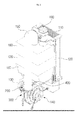
- the combustion apparatus includes an air intake hole 110 to which external air is introduced, an air preheating part 120 defining a supply channel of the air introduced through the air intake hole 110 and at the same time defining an exhaust channel of an exhaust gas, which is separated from the supply channel of the air; an air supply tube 130 through which the air passing through the air preheating part 120 moves a premixing chamber 200 in which the air introduced through the air supply tube 130, a combustion gas, and a recirculated exhaust gas are premixed a mixed-gas adjusting part 300 adjusting a section area of a passage through which the air and the gas flow in the premixing chamber 200 to adjust a supply flow rate of the mixed-gas, a blower 140 transferring the mixed-gas to a burner, a combustion chamber 160 in which the mixed-gas supplied thorough the supply tube 150 by being transferred from the blower 140 is burnt by ignition of the burner, a heat exchanger 170 heating water circulating therein by using combustion heat generated from
- the premixing chamber 200 is connected to an inlet-side of the blower 140.
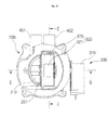
- An inner space of the premixing chamber 200 is divided into a first passage 210 and a second passage 220 by a partition member 201 therebetween.
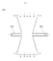
- the premixing chamber 200 has a venturi shape having a throat part, which is gradually reduced in section area from an inlet and an outlet toward the center thereof, in a central portion between the inlet to which the air is introduced and the outlet from which the mixed-gas is discharged toward the blower 140. That is, the premixing chamber 200 has a shape in which each of the inlet and the outlet of the air has a relatively wide section area, and the premixing chamber 200 gradually decreases in section area from the inlet and the outlet toward the throat part of the center thereof.
- a gas supply part 230 connected to a combustion gas supply tube (not shown) is disposed on one side of the throat part of the premixing chamber 200. Also, a mixed-gas adjusting part 300 is disposed on the other side of the throat part.
- a first exhaust gas recirculation tube 401 is connected to the throat part of the first passage 210, and a second exhaust gas recirculation tube 402 is connected to a front side of the throat part of the second passage 220.
- a first gas supply hole 231 connected to the first passage 210 and a second gas supply hole 232 connected to the second passage 220 are defined in the gas supply part 230.
- the first passage 210 of the premixing chamber 200 has a flow passage of the air and the gas that is in an opened state all the time. Also, a flow passage of the air and the gas of the second passage 220 is opened when a combustion load is more than a set load and is closed when the combustion load is less than the set load, by an operation of the mixed-gas adjusting part 300.
- the exhaust gas recirculation tubes 400 (401, 402) defines a flow passage through which a portion of the heat-exchanged exhaust gas recirculates to be introduced into the premixing chamber 200.
- An inlet of the exhaust gas recirculation tube 400 may pass through the heat exchanger 170 and disposed on a predetermined position between the exhaust gas discharge part 180 and the duct 190.
- the mixed-gas of the air, the combustion gas, and the recirculated exhaust gas premixed with each other in the premixing chamber 200 may be suctioned into the blower 140 by rotation of a fan disposed in the blower 140 and then be supplied to the mixed-gas supply tube 150 through a mixed-gas discharge hole 141.
- the air passing through the throat part has a flow rate that is relatively higher than that of the air at each of the inlet and outlet of the premixing chamber 200 and a pressure that is lower than that of each of the inlet and outlet of the premixing chamber 200, and thus a differential pressure may occur between the inlet and outlet of the premixing chamber 200 and the throat part.
- the gas and the exhaust gas introduced into the throat part having a relatively low pressure due to the differential pressure are also proportionally controlled in flow rate so that the flow rate is maintained in a predetermined air-fuel ratio.
- the first and second passages 210 and 220 partitioned into two sides in the premixing chamber 200 by the partition member 201 are defined, and the throat part having a relatively narrow section area when compared to the inlet and the outlet of the premixing chamber 200 is defined in each of a central portion of the first passage 210 and a central portion of the second passage 220.
- a first gas supply hole 231 and a second gas supply hole 232 spaced upward from the first gas supply hole 231 are defined in one side surface of the throat part of the first passage 210.
- a first gas supply passage 231a is defined from the first gas supply hole 231 to the partition member 201 across the first passage 210.
- a first gas jet hole 231b is defined in the first gas supply passage 231a toward an outlet-side of the first passage 210.
- a second gas supply passage 232a is defined from the second gas supply hole 232 to pass through the partition member 201 across the first passage 210 to communicate with the second passage 220.
- a second gas connection hole 232b is defined on an end of the second gas supply passage 232a passing through the partition member 201 toward the second passage 220.
- the first and second gas supply passages 231a and 232a are parallelly disposed to be vertically spaced apart from each other.
- a flow passage of the air is defined in a space between an inner wall of the first passage 210 and the first and second gas supply passages 231a and 232a.
- each of the flow passage of the air and the flow passage of the gas are in opened state all the time.
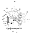
- the mixed-gas adjusting part 300 includes a first opening/closing member 320 for opening and closing the flow passage of the air passing through the second passage 220 and a second opening/closing member 330 for opening and closing the second gas connection hole 232b.
- the first and second opening/closing members 320 and 330 are linked to each other and opened and closed at the same time.
- the first opening/closing member 320 includes a main body 321 coupled to a rotation shaft 311a of a driving part 310 and transversally disposed in the throat part of the second passage 220 and blades 323 coupled to an outer surface of the main body 321 in a distance at an angle of 180°.
- the blades 323 have a size corresponding to that of an opened transversal section of the throat part of the second passage 220.
- the flow passage of the air of the second passage 220 may be blocked.
- the flow passage of the air is opened through a space spaced apart form an inner side surface of the second passage 220.
- the driving part 310 includes a motor 311 and a bracket 312 inserted and coupled to a coupling hole 250 defined in one side surface of the premixing chamber 200 in order to fix the motor 311 to the one side of the premixing chamber 200 by passing the rotation shaft 311 therethrough.
- the rotation shaft 311a is fitted and coupled to a rotation shaft coupling groove 321a defined in the main body 321 of the first opening/closing member 320 to allow the first opening/closing member 320 to rotate when the motor 311 is driven.
- the second opening/closing member 330 is linked to rotation of the first opening/closing member 320 to reciprocate in a transversal direction to open and close the second gas connection hole 232b of the second gas supply hole 232. Also, a sealing member 340 for maintaining air-tightness when the second gas connection hole 232b is sealed is disposed on the second opening/closing member 330.
- a first cam-shaped part 322 in which a first tip portion 322a protruding toward the second opening/closing member 330 and a first bottom portion 322b oppositely recessed with respect to the first tip portion 322a are alternately disposed at an angle of 90° along a circumferential direction, and a first inclined portion 322c having a concave shape is disposed between the first tip portion 322a and the first bottom portion 322b is disposed on the main body 321 of the first opening/closing member 320.
- a second cam-shaped part 332 having a second tip portion 322a, a second bottom portion 332b, and a second inclined portion 332c each of which has a shape corresponding to that of each of the first tip portion 322a, the first bottom portion 322b, and the first inclined portion 322c is disposed on the main body 331 of the second opening/closing member 330. Also, the second opening/closing member 330 is elastically supported so that the second opening/closing member 330 is pressed toward the first opening/closing member 320 by an elastic member 350.
- the second opening/closing member 330 may reciprocate toward the second gas connection hole 232b or in a direction far away from the second gas connection hole 232b according to positions of the first and second cam-shaped parts 322 and 332 when the first opening/closing member 320.
- a guide member 360 accommodating the second opening/closing member 330 and the elastic member 350 therein to guide a reciprocating motion of the second opening/closing member 330 is disposed on the throat part of the second passage 220.
- a second gas jet hole 364 is defined in the guide member 360 toward and outlet-side of the second passage 220.
- Protruding pieces 333 (333a, 333b) for supporting one end of the elastic member 350 are disposed on an edge of the main body 331 of the second opening/closing member 330 along a circumferential direction.
- a plurality of guide grooves 363 for guiding the plurality of protruding pieces 333 (333a, 333b) to reciprocate in a horizontal direction are defined in an inner surface of the guide member 360 along a longitudinal direction.
- Fixing projections 362a and 362b and fixing grooves (not shown) that are fitted and coupled to each other are respectively formed on the flange part 362 of the guide member 360 and the circumferential surface of the second gas connection hole 232b.
- the blade 323 of the first opening/closing member 320 is vertically disposed to stand upright with respect to the transversal section of the second passage 220 to open the flow passage of the air passing through the second passage 220 and simultaneously to cause a phase difference between the first and second tip portions 322a and 332a at an angle of 90°.
- the first tip portion 322a of the first opening/closing member 320 contact the second bottom portion 332b of the second opening/closing member 330, and at the same time, the first bottom portion 322b of the first opening/closing member 320 contact the second tip portion 332a of the second opening/closing member 330.
- the second opening/closing member 330 move in a direction far away from the second gas connection hole 232b by an elastic force of the elastic member 350 to open the second gas connection hole 232b.
- the air, the gas, and the recirculated exhaust gas may be introduced through the second passage 330 as well as the first passage 320 and mixed with each other.
- the combustion gas that is introduced through the first gas supply hole 231 due to the differential pressure generated in the throat part passes through the first gas supply passage 231a and is jetted to the first premixing chamber 211 through the first gas jet hole 231b and simultaneously mixed with a portion of the exhaust gas introduced through the first exhaust gas recirculation tube 401 and then is discharged through the outlet of the first passage 210.
- the combustion gas that is introduced through the second gas supply hole 232 due to the differential pressure generated in the throat part is jetted to the second premixing chamber 221 through the second gas supply passage 232a, the second gas connection hole 232b, and the second gas jet hole 364 and simultaneously mixed with a portion of the exhaust gas introduced through the second exhaust gas recirculation tube 402 and is discharged through the outlet of the second passage 220.
- the blade 323 of the first opening/closing member 320 is horizontally disposed in a transversal-section direction of the second passage 220 to block the flow of the air through the second passage 220, and at the same time, the first tip portion 322a of the first opening/closing member 320 contact the second tip portion 332a of the second opening/closing member 330 at the same phase.
- the second opening/closing member 330 moves toward the second gas connection hole 232b regardless of the elastic force of the elastic member 350 to block the second gas connection hole 232b by the sealing member 340 coupled to the second opening/closing member 330.
- the air, the gas, and the recirculated exhaust gas may be supplied only through the first passage 320, and the supply of the air, the gas, and the exhaust gas through the second passage 330 may be blocked.
- the combustion gas that is introduced through the first gas supply hole 231 due to the differential pressure generated in the throat part passes through the first gas supply passage 231a and is jetted to the first premixing chamber 211 through the first gas jet hole 231b and simultaneously mixed with a portion of the exhaust gas introduced through the first exhaust gas recirculation tube 401 and is discharged through the outlet of the first passage 210.
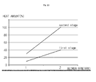
- FIG. 13 is a graph showing correlation of heat amount according to variation of the load.
- first stage low power
- second stage high power
- both of the first and second passages 210 and 220 are opened.
- the mixed-gas of the air, the combustion gas, and the recirculated exhaust gas having a uniform air-fuel ratio may be supplied by controlling the RPM of the blower 140 to secure a preset heat amount.
- the premixing chamber 200 may have a venture structure partitioned into two stages, and the first passage 210 may be in an opened state all the time, and the second passage 220 may be opened only at the time of high power load according to a combustion load area, and also a portion of the exhaust gas may recirculate to supply the mixed-gas in which the air, the combustion gas, and the exhaust gas are mixed with each other.
- combustion system that is reduced in flame temperature to significantly reduce the emission amount of nitrogen oxide and improved in combustion efficiency by perfect combustion and stable over an entire load area from the high power load to the low power load may be realized.
- the premixing chamber 200 has a venturi structure that is partitioned into the two stages, which are the first passage 210 and the second passage 220, as illustrated in FIG. 14
- the premixing chamber 200 according to the present invention may have a single passage venturi shape in which the gas supply part 230 and the exhaust gas recirculation tube 400 are connected to the throat part.
- the exhaust may recirculate in proportional to the differential pressure between the air and the gas passing through the throat part and then be introduced and mixed to supply the mixed-gas in which the air, the combustion gas, and the exhaust gas are mixed with each other at a uniform air-fuel ratio.
Landscapes
- Engineering & Computer Science (AREA)
- Chemical & Material Sciences (AREA)
- General Engineering & Computer Science (AREA)
- Mechanical Engineering (AREA)
- Combustion & Propulsion (AREA)
- Physics & Mathematics (AREA)
- General Physics & Mathematics (AREA)
- Business, Economics & Management (AREA)
- Educational Technology (AREA)
- Educational Administration (AREA)
- Theoretical Computer Science (AREA)
- Life Sciences & Earth Sciences (AREA)
- Environmental & Geological Engineering (AREA)
- General Life Sciences & Earth Sciences (AREA)
- Geology (AREA)
- Thermal Sciences (AREA)
- Entrepreneurship & Innovation (AREA)
- Paleontology (AREA)
- Algebra (AREA)
- Computational Mathematics (AREA)
- Mathematical Analysis (AREA)
- Mathematical Optimization (AREA)
- Mathematical Physics (AREA)
- Pure & Applied Mathematics (AREA)
- Geochemistry & Mineralogy (AREA)
- Gas Burners (AREA)
Applications Claiming Priority (2)
| Application Number | Priority Date | Filing Date | Title |
|---|---|---|---|
| KR1020130007209A KR101400834B1 (ko) | 2013-01-23 | 2013-01-23 | 연소장치 |
| PCT/KR2014/000176 WO2014115981A1 (fr) | 2013-01-23 | 2014-01-08 | Appareil de combustion |
Publications (2)
| Publication Number | Publication Date |
|---|---|
| EP2949994A1 true EP2949994A1 (fr) | 2015-12-02 |
| EP2949994A4 EP2949994A4 (fr) | 2016-08-24 |
Family
ID=50895646
Family Applications (1)
| Application Number | Title | Priority Date | Filing Date |
|---|---|---|---|
| EP14742810.6A Withdrawn EP2949994A4 (fr) | 2013-01-23 | 2014-01-08 | Appareil de combustion |
Country Status (7)
| Country | Link |
|---|---|
| US (1) | US9777919B2 (fr) |
| EP (1) | EP2949994A4 (fr) |
| JP (1) | JP6042558B2 (fr) |
| KR (1) | KR101400834B1 (fr) |
| CN (1) | CN104937340B (fr) |
| CA (1) | CA2895700C (fr) |
| WO (1) | WO2014115981A1 (fr) |
Cited By (4)
| Publication number | Priority date | Publication date | Assignee | Title |
|---|---|---|---|---|
| EP2927585A4 (fr) * | 2012-12-03 | 2016-09-07 | Kyung Dong Navien Co Ltd | Double venturi pour chambre de combustion |
| EP2988066A4 (fr) * | 2013-04-16 | 2016-12-21 | Kyungdong Navien Co Ltd | Double venturi pour dispositif de combustion |
| EP3745026A1 (fr) * | 2019-05-31 | 2020-12-02 | LG Electronics Inc. | Four à gaz |
| EP3734183A4 (fr) * | 2017-12-29 | 2021-10-06 | Kyungdong Navien Co., Ltd. | Chaudière à tube de fumée |
Families Citing this family (19)
| Publication number | Priority date | Publication date | Assignee | Title |
|---|---|---|---|---|
| KR101320113B1 (ko) * | 2012-02-28 | 2013-10-18 | 주식회사 경동나비엔 | 온수기용 듀얼 벤추리 |
| JP6571445B2 (ja) * | 2015-08-11 | 2019-09-04 | パーパス株式会社 | 予混合装置および熱源装置 |
| KR101888077B1 (ko) * | 2015-12-11 | 2018-08-13 | 주식회사 경동나비엔 | 연소기기용 가스밸브 |
| KR101727627B1 (ko) * | 2016-04-25 | 2017-05-02 | 최혁순 | 유해가스 재연소 장치 |
| JP6662194B2 (ja) * | 2016-05-20 | 2020-03-11 | 三浦工業株式会社 | 熱媒ボイラシステム |
| US10876744B2 (en) * | 2017-03-13 | 2020-12-29 | Rheem Manufacturing Company | Fuel enrichment system for fuel-fired appliance |
| CN107327846A (zh) * | 2017-07-28 | 2017-11-07 | 佛山市沃克曼普电气有限公司 | 预混合压力式燃气供给系统 |
| KR101929028B1 (ko) | 2018-04-27 | 2018-12-13 | 최문기 | 보일러의 배기가스 재순환장치 |
| JP7079968B2 (ja) * | 2018-05-09 | 2022-06-03 | 株式会社パロマ | 予混合装置及び燃焼装置 |
| KR102084524B1 (ko) * | 2018-05-28 | 2020-03-04 | 주식회사 더방신소재 | 산화물 분말 제조장치 |
| CN109357286A (zh) * | 2018-12-13 | 2019-02-19 | 北方民族大学 | 一种不易爆裂的机械结构打火装置及使用方法 |
| CN109442756A (zh) * | 2018-12-15 | 2019-03-08 | 成都前锋电子有限责任公司 | 一种装有进气稳压调节器的全预混凝式燃气采暖热水炉 |
| KR102365202B1 (ko) | 2020-02-21 | 2022-02-21 | 최혁순 | 유해가스 재연소 장치 |
| DE102020202950A1 (de) | 2020-03-06 | 2021-09-09 | Robert Bosch Gesellschaft mit beschränkter Haftung | Brenner zum Verbrennen eines Brennstoff-Luft-Gemischstroms sowie Heizgerät mit einem solchen Brenner |
| CN111828976A (zh) * | 2020-07-16 | 2020-10-27 | 广东万和新电气股份有限公司 | 一种可调节预混器及燃气热水器 |
| CN113048802B (zh) * | 2021-04-12 | 2022-11-08 | 重庆赛迪热工环保工程技术有限公司 | 多控制段加热炉低热负荷时降低氮氧化物的方法 |
| US12601477B2 (en) * | 2022-03-08 | 2026-04-14 | Bertelli & Partners S.R.L. | Device and method for controlling a fuel-oxidizer mixture for a premix gas burner |
| KR20240083673A (ko) * | 2022-12-05 | 2024-06-12 | 주식회사 경동나비엔 | 듀얼 벤추리 |
| CN118936099B (zh) * | 2024-08-14 | 2025-06-20 | 南京科达新控仪表有限公司 | 一种工业炉排气处理控制系统及控制方法 |
Family Cites Families (16)
| Publication number | Priority date | Publication date | Assignee | Title |
|---|---|---|---|---|
| US3837813A (en) * | 1973-02-01 | 1974-09-24 | Black Sivalls & Bryson Inc | Waste gas incinerator |
| US4334855A (en) * | 1980-07-21 | 1982-06-15 | Honeywell Inc. | Furnace control using induced draft blower and exhaust gas differential pressure sensing |
| JPS5730656U (fr) * | 1980-07-25 | 1982-02-18 | ||
| JPS59200118A (ja) * | 1983-04-27 | 1984-11-13 | Matsushita Electric Ind Co Ltd | 燃料空気混合装置 |
| US5511971A (en) * | 1993-08-23 | 1996-04-30 | Benz; Robert P. | Low nox burner process for boilers |
| JP3255395B2 (ja) * | 1995-07-17 | 2002-02-12 | パロマ工業株式会社 | 燃焼装置 |
| JP3795951B2 (ja) * | 1996-01-31 | 2006-07-12 | 三洋電機株式会社 | 低NOxバーナおよび排ガス再循環制御方法 |
| KR100361645B1 (ko) * | 1999-12-15 | 2002-11-23 | 한국에너지기술연구원 | 배기가스 재순환방식에 의한 저질소산화물 소형 응축식 가스보일러 구조 |
| JP2001173949A (ja) * | 1999-12-16 | 2001-06-29 | Harman Co Ltd | 燃焼装置 |
| DE10114903A1 (de) * | 2001-03-26 | 2002-10-17 | Invent Gmbh Entwicklung Neuer Technologien | Brenner für ein Gas/Luft-Gemisch |
| KR100805630B1 (ko) | 2006-12-01 | 2008-02-20 | 주식회사 경동나비엔 | 가스보일러의 연소장치 |
| DE102007008460A1 (de) | 2007-02-19 | 2008-08-21 | Viessmann Werke Gmbh & Co Kg | Mischeinrichtung für einen Gasgebläsebrenner |
| KR100838163B1 (ko) | 2007-03-27 | 2008-06-13 | 주식회사 대열보일러 | 저 질소산화물 인버터 보일러 및 그 연소 제어 방법 |
| JP2009174766A (ja) * | 2008-01-23 | 2009-08-06 | Miura Co Ltd | 燃焼装置 |
| ITBO20080278A1 (it) * | 2008-04-30 | 2009-11-01 | Gas Point S R L | Bruciatore a gas a pre-miscelazione |
| KR101204457B1 (ko) * | 2011-05-18 | 2012-11-23 | 주식회사 수국 | 저녹스형 버너 |
-
2013
- 2013-01-23 KR KR1020130007209A patent/KR101400834B1/ko active Active
-
2014
- 2014-01-08 CA CA2895700A patent/CA2895700C/fr active Active
- 2014-01-08 CN CN201480005776.0A patent/CN104937340B/zh not_active Expired - Fee Related
- 2014-01-08 EP EP14742810.6A patent/EP2949994A4/fr not_active Withdrawn
- 2014-01-08 US US14/648,253 patent/US9777919B2/en active Active
- 2014-01-08 WO PCT/KR2014/000176 patent/WO2014115981A1/fr not_active Ceased
- 2014-01-08 JP JP2015545384A patent/JP6042558B2/ja not_active Expired - Fee Related
Cited By (7)
| Publication number | Priority date | Publication date | Assignee | Title |
|---|---|---|---|---|
| EP2927585A4 (fr) * | 2012-12-03 | 2016-09-07 | Kyung Dong Navien Co Ltd | Double venturi pour chambre de combustion |
| EP2988066A4 (fr) * | 2013-04-16 | 2016-12-21 | Kyungdong Navien Co Ltd | Double venturi pour dispositif de combustion |
| US10047952B2 (en) | 2013-04-16 | 2018-08-14 | Kyungdong Navien Co., Ltd. | Dual venturi for combustion device |
| EP3734183A4 (fr) * | 2017-12-29 | 2021-10-06 | Kyungdong Navien Co., Ltd. | Chaudière à tube de fumée |
| EP3745026A1 (fr) * | 2019-05-31 | 2020-12-02 | LG Electronics Inc. | Four à gaz |
| EP3957911A1 (fr) * | 2019-05-31 | 2022-02-23 | LG Electronics Inc. | Four à gaz |
| US11441785B2 (en) | 2019-05-31 | 2022-09-13 | Lg Electronics Inc. | Gas furnace |
Also Published As
| Publication number | Publication date |
|---|---|
| CN104937340B (zh) | 2016-11-23 |
| US9777919B2 (en) | 2017-10-03 |
| US20150316254A1 (en) | 2015-11-05 |
| JP6042558B2 (ja) | 2016-12-14 |
| KR101400834B1 (ko) | 2014-05-29 |
| CA2895700A1 (fr) | 2014-07-31 |
| CN104937340A (zh) | 2015-09-23 |
| JP2016502640A (ja) | 2016-01-28 |
| CA2895700C (fr) | 2017-08-08 |
| WO2014115981A1 (fr) | 2014-07-31 |
| EP2949994A4 (fr) | 2016-08-24 |
Similar Documents
| Publication | Publication Date | Title |
|---|---|---|
| CA2895700C (fr) | Appareil de combustion dote d'un conduit d'evacuation a recirculation | |
| CN112682783B (zh) | 燃烧器和燃气热水器 | |
| CA2896605C (fr) | Type de chemin d'ecoulement separe de dispositif de melange gaz-air | |
| CN104246369B (zh) | 提高调节比的燃烧装置 | |
| US9702589B2 (en) | Combustion apparatus having air intake preheater | |
| US20110139045A1 (en) | Premix gas burner | |
| JP6833265B2 (ja) | 予混合式ガスバーナ | |
| KR100795595B1 (ko) | 가스 연소장치 | |
| CN216953216U (zh) | 燃气采暖装置 | |
| CN211345295U (zh) | 一种无级变速燃烧器 | |
| CN223307107U (zh) | 燃烧系统及具有该系统的燃气热水器 | |
| CN223595916U (zh) | 燃烧器和烹饪器具 | |
| JPH041247B2 (fr) | ||
| CN212481284U (zh) | 燃烧器 | |
| JPH1151560A (ja) | 乾燥炉 | |
| CN120212508A (zh) | 风道结构、燃烧装置、燃烧系统及燃烧设备 | |
| CN120212504A (zh) | 风道结构、燃烧装置、燃烧系统及燃气设备 | |
| CN120609070A (zh) | 一种燃烧炉 | |
| CN115560323A (zh) | 燃烧器及燃气热水器 | |
| JP2004226049A (ja) | 熱風発生装置 |
Legal Events
| Date | Code | Title | Description |
|---|---|---|---|
| PUAI | Public reference made under article 153(3) epc to a published international application that has entered the european phase |
Free format text: ORIGINAL CODE: 0009012 |
|
| 17P | Request for examination filed |
Effective date: 20150529 |
|
| AK | Designated contracting states |
Kind code of ref document: A1 Designated state(s): AL AT BE BG CH CY CZ DE DK EE ES FI FR GB GR HR HU IE IS IT LI LT LU LV MC MK MT NL NO PL PT RO RS SE SI SK SM TR |
|
| AX | Request for extension of the european patent |
Extension state: BA ME |
|
| DAX | Request for extension of the european patent (deleted) | ||
| A4 | Supplementary search report drawn up and despatched |
Effective date: 20160722 |
|
| RIC1 | Information provided on ipc code assigned before grant |
Ipc: F23D 14/46 20060101AFI20160718BHEP Ipc: F23D 14/68 20060101ALI20160718BHEP Ipc: F23D 14/62 20060101ALI20160718BHEP |
|
| GRAP | Despatch of communication of intention to grant a patent |
Free format text: ORIGINAL CODE: EPIDOSNIGR1 |
|
| INTG | Intention to grant announced |
Effective date: 20170630 |
|
| STAA | Information on the status of an ep patent application or granted ep patent |
Free format text: STATUS: THE APPLICATION IS DEEMED TO BE WITHDRAWN |
|
| 18D | Application deemed to be withdrawn |
Effective date: 20171111 |