EP2950068A1 - Temperatursensor - Google Patents
Temperatursensor Download PDFInfo
- Publication number
- EP2950068A1 EP2950068A1 EP15169938.6A EP15169938A EP2950068A1 EP 2950068 A1 EP2950068 A1 EP 2950068A1 EP 15169938 A EP15169938 A EP 15169938A EP 2950068 A1 EP2950068 A1 EP 2950068A1
- Authority
- EP
- European Patent Office
- Prior art keywords
- temperature sensor
- sensor system
- tube
- measuring device
- thermally conductive
- Prior art date
- Legal status (The legal status is an assumption and is not a legal conclusion. Google has not performed a legal analysis and makes no representation as to the accuracy of the status listed.)
- Granted
Links
Images

Classifications
-
- G—PHYSICS
- G01—MEASURING; TESTING
- G01K—MEASURING TEMPERATURE; MEASURING QUANTITY OF HEAT; THERMALLY-SENSITIVE ELEMENTS NOT OTHERWISE PROVIDED FOR
- G01K1/00—Details of thermometers not specially adapted for particular types of thermometer
- G01K1/14—Supports; Fastening devices; Arrangements for mounting thermometers in particular locations
- G01K1/146—Supports; Fastening devices; Arrangements for mounting thermometers in particular locations arrangements for moving thermometers to or from a measuring position
Definitions
- the present invention relates to a temperature sensor system for the beverage or packaging industry according to claim 1. Furthermore, the subject of the invention is a measuring device according to claim 10.
- the object of the present invention is to provide a temperature sensor system and a measuring device, which ensure an accurate temperature measurement within containers and also have a sufficiently high mechanical stability.
- a temperature sensor system having the features of claim 1 and a measuring device having the features of claim 10.
- Advantageous embodiments are the subject matter of the dependent claims. It should be noted that the features listed individually in the claims can also be combined with one another in any desired and technologically sensible manner and thus show further embodiments of the invention.
- the measuring device according to the invention can also be designed with the temperature sensor system according to the invention.
- a temperature sensor system for the beverage and / or packaging industry has at least one tube with a first and a second end, wherein the tube has a low thermal conductivity. Furthermore, the temperature sensor system has a temperature sensor, which is arranged in the interior of the tube. Advantageously, the temperature sensor is in the region of the first end of the tube. Furthermore, the system according to the invention has a thermally conductive element, which is arranged at an opening of the first end of the tube.
- the temperature sensor arrangement according to the invention has the advantage over the prior art that by using a tube with a low thermal conductivity on one side and a thermally conductive element at the opening of the tube on the other side, the temperature of the container interior can be measured punctually and accurately ,
- a low thermal conductivity is understood to be a value below 12 W / (m * K), preferably a value below 5 W / (m * K) and particularly preferably a value below 1 W / (m * K).
- the temperature sensor measures a falsified value, since the elements of the temperature sensor system or of the measuring device also influence the result of the measurement of the temperature and can thus falsify the temperature actually present in the container.
- the temperature sensor may be a ceramic chip having a diameter of about 1 mm, preferably about 0.8 mm. Furthermore, the sensor preferably has a length of about 3 mm, more preferably about 2 mm.
- the sensor can be designed with a platinum coating having a measured value or measured value range of approximately 100 ⁇ or 1000 ⁇ . It is also conceivable that the sensor has been artificially aged, whereby it is achieved that over the age of the sensor no measurement fluctuations occur and thus a readjustment, for example, in electronic, metrological nature is no longer necessary.
- the tube preferably has a high strength and / or rigidity. This prevents the tube from being deformed during the piercing process and the temperature sensor inside it being damaged.
- the tube may be made of a material having high weight-specific strength and / or rigidity. This offers the advantage that the temperature sensor system has a high rigidity and / or strength with a small construction volume. Consequently, the temperature sensor system can also be used in the temperature measurement in packaging or beverage containers, where only a small volume of construction is available. In particular, this is the case in the area of bottle necks.
- the tube according to the invention may be made of a fiber composite material.
- the advantage of fiber composites is that the mechanical or thermal properties of these materials can be easily adjusted via a large number of parameters.
- the tube is preferably a tube made of a fiber-plastic composite, more preferably of a carbon fiber-reinforced plastic.
- the advantage here is that these tubes have a particularly high stability and poor thermal conductivity.
- the matrix of the carbon fiber reinforced plastic preferably has thermosets, e.g. As epoxy or phenolic resins, on. But it can also be made of thermoplastics. It is also conceivable that the tube is made of a ceramic fiber composite material.
- the thermally conductive element may advantageously comprise silver.
- silver has a very good thermally conductive property, it can thereby be ensured that the temperature sensor, which is arranged in the interior of the tube, also detects the temperature to be measured without significant measurement errors.
- the thermally conductive element is an alloy of silver or, in addition to silver, it also contains additives. This offers the advantage that such a thermally conductive element is harder compared to a pure silver element, is more resistant to environmental influences and is also tarnish-resistant. If the silver starts to run over time, the thermal conductivity of the element deteriorates and the temperature to be measured can no longer be optimally transmitted to the temperature sensor. The measurements would be faulty. But it is also conceivable that the thermally conductive element of another metal, such as, copper, gold or aluminum or of another thermally conductive alloy.
- the thermally conductive element advantageously has a diameter which corresponds at least to the diameter of the opening of the tube. However, it preferably has a diameter which corresponds to the outer diameter of the tube. This will prevent the tube from fraying at the end.
- the thermally conductive element may be formed platelet-shaped.
- the thermally conductive element is preferably a bolt-shaped or pin-shaped element which protrudes from the opening of the pipe into the interior of the pipe. This offers the advantage that the element, by its elongated extent, transmits the temperature prevailing at the opening of the tube to the inside of the tube where the temperature sensor is located.
- the thermally conductive element is rivet-shaped.
- Such an element has an elongated body with a thickened end. The end may be formed, for example, half-round or flachrund.
- the thermally conductive element can touch the temperature sensor, so that the temperature to be measured is transmitted directly to the temperature sensor. It is also conceivable that the thermally conductive element and / or the temperature sensor are connected to the pipe with an adhesive. This ensures that the components remain in place even with vibrations or movements of the sensor system. Ideally, the thermally conductive element and the temperature sensor are mechanically bonded together with an adhesive. For this purpose, a thermally conductive adhesive is particularly well suited. As a result, a temperature transfer is achieved in the best possible way.
- the thermally conductive adhesive may be epoxy or silicone products, such as a 1-part thermosetting silicone or a 2-component epoxy adhesive. It is also conceivable that the thermally conductive adhesive has metal particles.
- the temperature sensor system according to the invention may have at least one connecting element in the region of the second end of the tube.
- this connecting element By means of this connecting element, it is possible to arrange the sensor system, for example, on a measuring device.
- connecting elements such elements are conceivable with which releasable connections, preferably positive or non-positive, can be produced.
- the connecting element may preferably have at least one thread, particularly preferably an external thread. It is also conceivable that the connecting element is designed such that it is part of a bayonet closure.
- the connecting element has at least one button. By means of this at least one button, the temperature sensor system can be connected to the other part of the bayonet closure, which has at least one longitudinal slot and an adjoining short transverse slot.
- the connecting element has at least one slot, wherein a button of the other part of the bayonet closure can be inserted.
- the connecting element can also perpendicular to a direction of insertion at a junction elongated elevations that are not run around, but are interrupted, as they are, for example, even with camera interchangeable lenses present.
- the connecting element may be part of the tube. But it can also be a separate component. If it is a separate component, then this is preferably positive or materially, for example. Connected by an adhesive to the pipe.
- the separate connection element may have a bore into which the tube is inserted.
- the connecting element has a stepped and / or a blind hole. This offers the advantage that the second end of the tube is protected by the connecting element and a failure of the tube is prevented.
- the present invention is also directed to a measuring device according to claim 10.
- the measuring device according to the invention has a measuring head, at least one temperature sensor system according to the invention, a mechanical receptacle, a piercing means and an evaluation unit.
- the piercing means is chamfered. This offers the advantage that the container can be pierced with relatively little force and also an accurate and punctured puncturing of the container can be ensured.
- the piercing means is preferably made of a hard material. It is also conceivable that the piercing means is a needle. Ideally, the piercing means is a hollow body, for example a tube.
- the temperature sensor system according to the invention can be arranged within the piercing means.
- the temperature sensor system is arranged protected in the piercing means and damage to the sensor system is prevented.
- the temperature sensor system is slightly narrower than the diameter of the cavity of the Stinging and touched this essentially or not at all. Thus, a temperature transfer from the piercing means to the temperature sensor is reliably avoided.
- the temperature sensor system and the piercing means are arranged relatively movable relative to each other. With such an arrangement, the temperature sensor system is completely protected within the piercing means during the piercing operation. After the piercing operation is completed, the sensor system is either pushed out of the piercing means by a moving mechanism, or the piercing means is retracted. It is also conceivable that both the piercing means retracted and the sensor system is pushed out. As a result, the sensor system protrudes beyond the piercing means and is in direct contact with the matter to be measured.
- An advantage of the direct temperature measurement is that only the temperature of the medium to be tested is detected and influencing the measurement result by influences from the measurement environment play a minor role, whereby measurement errors are low and the sensor reproduces the temperature prevailing in the medium to be tested accurately.
- the mechanical recording is equipped with a rotating and / or pivoting mechanism.
- the container can be shaken so as to achieve a state of equilibrium between the gas and liquid phase within the container and thus to be able to achieve an exact sample measurement.
- the piercing means may comprise means with which the pressure prevailing inside the container can be measured.
- the piercing means has at least one transverse bore at the end, via which the gas pressure in the container can be measured.
- the piercing means may be arranged on the measuring head.
- the piercing means can be firmly and unyieldingly fixed in the measuring head, but also be relatively movable by a movement mechanism to the measuring head.
- the relative mobility of the piercing means to the measuring head offers the advantage that in this way, for example, after Piercing process the piercing can be fed into the probe and thus the temperature sensor system is exposed.
- the temperature sensor system can also be arranged on the measuring head.
- the connection between the temperature sensor system and the measuring head can preferably be produced by the connecting means according to the invention. It is also conceivable that the sensor system is relatively movable to the measuring head.
- the container is sealed by the piercing means or by the measuring head, so that during and after piercing a pressure prevailing in the container overpressure and / or a liquid in the container can not escape.
- a flexible membrane seal is arranged on the measuring head. By this membrane seal the pierced container is sealed. Ideally, the membrane seal is pressed against the container with a counterpressure, whereby a gastight connection is produced.
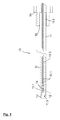
- Fig. 1 an inventive temperature sensor system 10 for the beverage and / or packaging industry is shown schematically in the side view.
- the system 10 a tube 11, which is preferably constructed of carbon fiber reinforced plastic and having a first 11.1 and a second end 11.2.
- a temperature sensor 12 is arranged in the interior of the tube, from which electrical leads 12.1 pass through the tube 11 to the measuring device 30, each having an insulation 12.2.
- a thermally conductive element 13 is arranged at an opening 11.3 of the first end 11.1 of the tube 11.
- the rivet 13 has an outer diameter which corresponds at least to the outer diameter of the tube 11.
- Both the rivet 13 and the temperature sensor 12 are fixed in the tube 11 by a thermally conductive adhesive 14.
- the thermally conductive adhesive By the thermally conductive adhesive, the positioning of the temperature sensor 12 and the rivet 13 is ensured on the one hand and on the other hand, a temperature transfer between the rivet 13 and the sensor 12 are best ensured.
- the temperature sensor 12 is a ceramic chip, which preferably has a diameter of about 1 mm.
- a hexagonal screw 15 is arranged at the second end 11.2 of the tube 11.
- the hexagon screw 15 has a stepped bore 15.1.
- the stepped bore has the advantage that the second end 11.2 is protected by the hex screw and thus can not fringe.
- the hexagon screw 15 is mechanically connected to an adhesive 16 on the tube 11.
- the temperature sensor system 10 can be connected to a measuring device 30, preferably to a measuring head 31 of a measuring device 30.
- another connecting means is arranged on the second end 11. 2 of the tube 11.
- a bayonet lock is particularly well suited.
- the tube 11 may have button-like elements in the region of the second end 11.2.
- a measuring device 30 for the beverage and / or packaging industry is shown schematically.
- the device 30 has a mechanical receptacle 32 for a container 50.
- the container 50 is preferably a bottle with a wall 50.2, which is closed by a lid 50.1. Within the container 50 is a drink.
- a level 50.5 of the beverage is indicated schematically. Above the level 50.5 is a head space 50.3, which is usually filled with a gaseous medium, which is preferably CO 2 -containing.
- the measuring device further comprises a piercing means 40, which is arranged on a measuring head 31.
- the piercing means 40 protrudes, for example, through the lid 50.1 of the container 50 into the drink.
- a temperature sensor system 10 according to the invention is located on the measuring head 11.
- the temperature sensor system 10 is arranged within the piercing means 40, the temperature sensor system 10 and the piercing means 40 being relatively movable relative to one another.
- the measuring device 30 further has a turning and / or pivoting mechanism 33, which securely receives or fixes the container 50 via the mechanical receptacle 32.
- the rotary and / or pivoting mechanism 33 is driven by an electromagnetic drive 33.1.
- the measuring head 31, which is also attached to the rotary and / or pivoting mechanism 33, may additionally have an evaluation unit 34 and a display 35. But it is also possible that the evaluation unit 34 and / or the display 15 are arranged independently of the rotary and / or pivoting mechanism 33 within the measuring device 30 stationary.
Landscapes
- Physics & Mathematics (AREA)
- General Physics & Mathematics (AREA)
- Measuring Temperature Or Quantity Of Heat (AREA)
Abstract
Description
- Die vorliegende Erfindung betrifft ein Temperatursensorsystem für die Getränke- bzw. Verpackungsindustrie nach Anspruch 1. Weiterhin ist Gegenstand der Erfindung eine Messvorrichtung nach Anspruch 10.
- Es ist allgemein bekannt, dass sowohl der Geschmack als auch die Haltbarkeit von Getränken, wie bspw. von Bieren, Limonaden oder Softdrinks, entscheidend vom Kohlendioxidgehalt in diesen Getränken beeinflusst wird. Folglich ist es notwendig den vorhandenen Kohlendioxidgehalt in den Behältnissen exakt bestimmen zu können. Aus dem Stand der Technik ist bekannt, dass die Bestimmung der Konzentration des Kohlendioxids im Behältnis bspw. dadurch indirekt erfolgen kann, dass im Behältnis der Druck und die Temperatur gemessen werden, nachdem ein Gleichgewichtszustand zwischen Gas- und Flüssigkeitsphase erzielt wurde. Bisher wurde für diese Messung ein Temperatursensor verwendet, der in einem Metallrohr angeordnet und mit diesem fest verbunden war. Nachteilig hierbei ist jedoch, dass die Temperatur des gesamten Metallrohrs auf den Sensor übertragen wurde. Somit musste einerseits eine große Masse erwärmt bzw. abgekühlt werden und andererseits strahlten somit auch die Temperaturen von Teilen der Messeinrichtung, die für die eigentlichen Messung irrelevant waren, über den ausstehenden Teil des Metallrohrs auf den Temperatursensor, so dass eine exakte Temperaturmessung innerhalb des Behältnisses schwierig ist. Ferner ist bei den bekannten Vorrichtungen der Nachteil, dass der Sensor beim Einstechen in das Behältnis oftmals beschädigt wurde, da sich das Metallrohr bzw. der Temperatursensor beim Einstechen verbog, wodurch diese ausgetauscht werden mussten.
- Die Aufgabe der vorliegenden Erfindung besteht daher darin, ein Temperatursensorsystem sowie eine Messvorrichtung zu schaffen, welche eine exakte Temperaturmessung innerhalb von Behältnissen gewährleisten und zudem eine ausreichend hohe mechanische Stabilität aufweisen.
- Gelöst wird diese Aufgabe durch ein Temperatursensorsystem mit den Merkmalen des Anspruchs 1 sowie eine Messvorrichtung mit den Merkmalen des Anspruchs 10. Vorteilhafte Ausgestaltungen sind jeweils Gegenstand der abhängigen Ansprüche. Es ist darauf hinzuweisen, dass die in den Patentansprüchen einzeln aufgeführten Merkmale auch in beliebiger und technologisch sinnvoller Weise miteinander kombiniert werden können und somit weitere Ausgestaltungen der Erfindung aufzeigen. Die erfindungsgemäße Messvorrichtung kann dabei auch mit dem erfindungsgemäßen Temperatursensorsystem ausgestaltet sein.
- Ein erfindungsgemäßes Temperatursensorsystem für die Getränke- und/oder Verpackungsindustrie weist zumindest ein Rohr mit einem ersten und einem zweiten Ende auf, wobei das Rohr eine niedrige Wärmeleitfähigkeit hat. Ferner weist das Temperatursensorsystem einen Temperatursensor auf, der im Inneren des Rohrs angeordnet ist. Vorteilhafterweise befindet sich der Temperatursensor im Bereich des ersten Endes des Rohrs. Des Weiteren weist das erfindungsgemäße System ein wärmeleitfähiges Element auf, welches an einer Öffnung des ersten Endes des Rohrs angeordnet ist.
- Die erfindungsgemäße Temperatursensoranordnung hat gegenüber dem Stand der Technik den Vorteil, dass durch die Verwendung eines Rohrs mit einer niedrigen Wärmeleitfähigkeit auf der einen Seite und einem wärmeleitfähigen Element an der Öffnung des Rohrs auf der anderen Seite, die Temperatur des Behälterinnenraums punktuell und genau gemessen werden kann. Als niedrige Wärmeleitfähigkeit wird ein Wert unter 12 W/(m*K) verstanden, bevorzugt ein Wert unter 5 W/(m*K) und besonders bevorzugt ein Wert unter 1 W/(m*K). Bei dem bekannten Stand der Technik misst der Temperatursensor einen verfälschten Wert, da auch die Elemente des Temperatursensorsystems bzw. der Messvorrichtung das Ergebnis der Messung der Temperatur beeinflussen und somit die eigentlich im Behältnis vorliegende Temperatur verfälschen können.
- Bei dem Temperatursensor kann es sich um einen Keramikchip handeln, der einen Durchmesser von etwa 1 mm, bevorzugt etwa 0,8 mm aufweist. Ferner weist der Sensor bevorzugt eine Länge von etwa 3 mm, besonders bevorzugt etwa 2 mm auf. Der Sensor kann mit einer Platinbeschichtung ausgestaltet sein, der einen Messwert bzw. Messwertbereich von ca. 100 Ω bzw. 1.000 Ω aufweist. Es ist auch denkbar, dass der Sensor künstlich gealtert worden ist, wodurch erreicht wird, dass über das Alter des Sensors keine Messschwankungen mehr auftreten und somit eine Nachjustierung bspw. in elektronischer, messtechnischer Art nicht mehr erforderlich ist.
- Das Rohr weist bevorzugt eine hohe Festigkeit und/oder Steifigkeit auf. So wird verhindert, dass sich das Rohr beim Anstechvorgang verformt und der darin liegende Temperatursensor beschädigt wird. Idealerweise kann das Rohr aus einem Material sein, das eine hohe gewichtsspezifische Festigkeit und/oder Steifigkeit aufweist. Dies bietet den Vorteil, dass das Temperatursensorsystem bei einem geringen Bauvolumen eine hohe Steifigkeit und/oder Festigkeit aufweist. Folglich kann das Temperatursensorsystem auch bei der Temperaturmessung in Verpackungen bzw. Getränkebehältnissen benutzt werden, wo nur ein geringes Bauvolumen zur Verfügung steht. Insbesondere ist dies im Bereich von Flaschenhälsen der Fall.
- Das erfindungsgemäße Rohr kann aus einem Faserverbundwerkstoff sein. Der Vorteil von Faserverbundwerkstoffen ist, dass über eine Vielzahl von Parametern die mechanischen bzw. thermischen Eigenschaften dieser Stoffe leicht eingestellt werden können. Neben der Faser-Matrix-Kombination können bspw. der Faserwinkel, der Faservolumenanteil, die Schichtreihenfolge und vieles mehr variiert werden. Bevorzugt handelt es sich bei dem Rohr um ein Rohr aus einem Faser-Kunststoff-Verbund, besonders bevorzugt aus einem kohlefaserverstärkten Kunststoff. Der Vorteil hierbei ist, dass diese Rohre über eine besonders hohe Stabilität und eine schlechte Wärmeleitfähigkeit verfügen. Die Matrix des kohlefaserverstärkten Kunststoffs weist bevorzugt Duromere, z. B. Epoxidharz oder Phenolharze, auf. Sie kann aber auch aus Thermoplasten sein. Denkbar ist aber auch, dass das Rohr aus einem keramischen Faserverbundwerkstoff ist.
- Das wärmeleitfähige Element kann vorteilhafterweise Silber aufweisen. Dadurch, dass Silber eine sehr gute wärmeleitfähige Eigenschaft aufweist, kann hierdurch gewährleistet werden, dass der Temperatursensor, der im Inneren des Rohrs angeordnet ist, die zu messende Temperatur auch ohne wesentliche Messfehler erfasst. Vorteilhafterweise handelt es sich bei dem wärmeleitfähigen Element um eine Legierung aus Silber bzw. es enthält neben Silber noch Zusatzstoffe. Dies bietet den Vorteil, dass ein solches wärmeleitfähiges Element gegenüber einem Element aus reinem Silber härter ist, gegenüber Umwelteinflüssen resistenter ist und zudem anlaufbeständig ist. Läuft das Silber mit der Zeit an, verschlechtert sich die Wärmeleitfähigkeit des Elements und die zu messende Temperatur könnte nicht mehr bestmöglich auf den Temperatursensor übertragen werden. Die Messungen würden fehlerhaft werden. Es ist aber auch denkbar, dass das wärmeleitfähige Element aus einem anderen Metall, wie bspw. Kupfer, Gold oder Aluminium bzw. aus einer anderen wärmeleitfähigen Legierung ist.
- Das wärmeleitfähige Element weist vorteilhafterweise einen Durchmesser auf, der wenigstens den Durchmesser der Öffnung des Rohrs entspricht. Bevorzugt weist es aber einen Durchmesser auf, der dem Außendurchmesser des Rohrs entspricht. Hierdurch wird verhindert, dass das Rohr am Ende ausfranzen kann.
- Das wärmeleitfähige Element kann plättchenförmig ausgebildet sein. Bevorzugt handelt es sich bei dem wärmeleitfähigen Element um ein bolzen- bzw. stiftförmiges Element, das von der Öffnung des Rohrs in das Rohrinnere ragt. Dies bietet den Vorteil, dass das Element, durch seine längliche Ausdehnung, die an der Öffnung des Rohrs herrschende Temperatur auf die Rohrinnenseite, wo sich der Temperatursensor befindet, überträgt. Besonders bevorzugt ist das wärmeleitfähige Element nietförmig ausgebildet. Ein solches Element weist einen länglichen Körper mit einem verdickten Ende auf. Das Ende kann dabei bspw. halbrund oder flachrund ausgebildet sein. Durch eine nietförmige Ausgestaltung, weist das wärmeleitfähige Element im Bereich der Öffnung des Rohrs eine größtmögliche Ausdehnung auf, wodurch die zu messende Temperatur vom wärmeleitfähigen Element optimal erfasst werden kann.
- Innerhalb des Temperatursensorsystems kann das wärmeleitfähige Element den Temperatursensor berühren, so dass die zu messende Temperatur direkt an den Temperatursensor übertragen wird. Denkbar ist auch, dass das wärmeleitfähige Element und/oder der Temperatursensor mit einem Kleber mit dem Rohr verbunden sind. Hierdurch wird gewährleistet, dass die Bauteile auch bei Erschütterungen bzw. Bewegungen des Sensorsystems an ihrem Platz bleiben. Idealerweise sind das wärmeleitfähige Element und der Temperatursensor mit einem Kleber mechanisch miteinander verbunden. Hierzu eignet sich besonders gut ein wärmeleitfähiger Kleber. Hierdurch kann eine Temperaturübertragung bestmöglich erzielt wird. Bei dem wärmeleitfähigen Kleber kann es sich um Epoxid- bzw. Silikonprodukte, wie bspw. ein warmhärtendes 1-Komponenten-Silikon oder einen 2-Komponenten-Epoxidharz-Klebstoff, handeln. Denkbar ist aber auch, dass der wärmeleitfähige Kleber Metallpartikel aufweist.
- Das erfindungsgemäße Temperatursensorsystem kann im Bereich des zweiten Endes des Rohrs wenigstens ein Verbindungselement aufweisen. Durch dieses Verbindungselement ist es möglich das Sensorsystem bspw. an einer Messvorrichtung anzuordnen. Als Verbindungselemente sind solche Elemente vorstellbar, mit denen lösbare Verbindungen, bevorzugt form- oder kraftschlüssige, hergestellt werden können. Bevorzugt kann das Verbindungselement wenigstens ein Gewinde, besonders bevorzugt ein Außengewinde, aufweisen. Denkbar ist auch, dass das Verbindungselement derart ausgestaltet ist, dass es ein Teil eines Bajonettverschlusses ist. Das Verbindungselement weist dabei wenigstens einen Knopf auf. Durch diesen wenigstens einen Knopf kann das Temperatursensorsystem mit dem anderen Teil des Bajonettverschlusses, der wenigstens einen Längsschlitz und einen daran anschließenden kurzen Querschlitz aufweist, verbunden werden. Vorstellbar ist auch, dass das Verbindungselement wenigstens einen Schlitz aufweist, worin ein Knopf des anderen Teils des Bajonettverschlusses eingeführt werden kann. Das Verbindungselement kann aber auch senkrecht zu einer Steckrichtung an einer Verbindungsstelle längliche Erhebungen, die nicht rundum laufen, sondern unterbrochen sind, wie sie bspw. auch bei Kamerawechselobjektiven vorhanden sind, aufweisen.
- Das Verbindungselement kann Teil des Rohrs sein. Es kann aber auch ein separates Bauteil sein. Handelt es sich um ein separates Bauteil, so wird dieses bevorzugt form- oder stoffschlüssig, bspw. durch einen Klebstoff, mit dem Rohr verbunden. Das separate Verbindungselement kann eine Bohrung aufweisen, in die das Rohr eingeschoben wird. Bevorzugt weist das Verbindungselement eine Stufen- und/oder eine Sacklochbohrung auf. Dies bietet den Vorteil, dass das zweite Ende des Rohrs von dem Verbindungselement geschützt wird und ein Ausfranzen des Rohrs verhindert wird.
- Ferner ist die vorliegende Erfindung auch auf eine Messvorrichtung gemäß Anspruch 10 gerichtet. Die erfindungsgemäße Messvorrichtung weist einen Messkopf, zumindest ein erfindungsgemäßes Temperatursensorsystem, eine mechanische Aufnahme, ein Anstechmittel und eine Auswerteeinheit auf.
- Durch das Anstechmittel kann ein Behältnis, das sich in einer mechanischen Aufnahme befindet bzw. dessen Deckel, durchstochen werden. Hierdurch ist es möglich, dass die Temperatur im Inneren des Behältnisses direkt gemessen werden kann, da das Temperatursensorsystem nach dem Anstechen innerhalb des Behältnisses angeordnet werden kann. Bevorzugt ist das Anstechmittel angeschrägt. Dies bietet den Vorteil, dass das Behältnis mit relativ wenig Kraft durchstochen werden kann und zudem ein genaues und punktuelles Anstechen des Behältnisses gewährleistet werden kann. Das Anstechmittel ist bevorzugt aus einem harten Werkstoff. Es ist auch denkbar, dass es sich bei dem Anstechmittel um eine Nadel handelt. Idealerweise ist das Anstechmittel ein hohler Körper, bspw. ein Rohr.
- Des Weiteren kann das erfindungsgemäße Temperatursensorsystem innerhalb des Anstechmittels angeordnet sein. Vorteilhaft hierbei ist unter anderem, dass während des Anstechvorgangs das Temperatursensorsystem geschützt im Anstechmittel angeordnet ist und eine Beschädigung des Sensorsystems verhindert wird. Bevorzugt ist das Temperatursensorsystem etwas schmaler als der Durchmesser des Hohlraums des Anstechmittels und berührt dieses im Wesentlichen oder überhaupt nicht. Somit wird auch eine Temperaturübertragung vom Anstechmittel auf den Temperatursensor zuverlässig vermieden.
- Idealerweise sind das Temperatursensorsystem und das Anstechmittel relativ beweglich zueinander angeordnet. Bei einer derartigen Anordnung liegt beim Anstechvorgang das Temperatursensorsystem vollständig geschützt innerhalb des Anstechmittels. Nachdem der Anstechvorgang beendet ist, wird das Sensorsystem durch einen Bewegungsmechanismus entweder aus dem Anstechmittel herausgeschoben oder das Anstechmittel wird eingezogen. Denkbar ist auch, dass sowohl das Anstechmittel eingezogen als auch das Sensorsystem herausgeschoben wird. Im Ergebnis ragt das Sensorsystem dann über das Anstechmittel heraus und steht in einem direkten Kontakt mit der zu messenden Materie. Vorteilhaft bei der direkten Temperaturmessung ist, dass lediglich die Temperatur des zu prüfenden Mediums erfasst wird und eine Beeinflussung des Messergebnisses durch Einflüsse aus der Messumgebung eine möglichst untergeordnete Rolle spielen, wodurch Messfehler gering ausfallen und der Sensor die im zu prüfenden Medium herrschende Temperatur bestgenau wiedergibt.
- Denkbar ist, dass die mechanische Aufnahme mit einem Dreh- und/oder Schwenkmechanismus ausgestattet ist. Durch einen derartigen Mechanismus kann das Behältnis geschüttelt werden, um somit einen Gleichgewichtszustand zwischen der Gas- und Flüssigkeitsphase innerhalb des Behälters zu erreichen und damit eine exakte Probemessung erzielen zu können.
- Ferner kann das Anstechmittel Mittel aufweisen, mit denen der Druck, der innerhalb des Behältnisses herrscht, gemessen werden kann. Hierfür ist es denkbar, dass das Anstechmittel am Ende mindestens eine Querbohrung aufweist, über die der Gasdruck im Behältnis gemessen werden kann.
- Das Anstechmittel kann an dem Messkopf angeordnet sein. Das Anstechmittel kann dabei fest und unnachgiebig im Messkopf fixiert sein, aber auch relativ beweglich durch einen Bewegungsmechanismus zu dem Messkopf sein. Die relative Beweglichkeit des Anstechmittels zu dem Messkopf bietet den Vorteil, dass hierdurch bspw. nach dem Anstechvorgang das Anstechmittel in den Messkopf eingezogen werden kann und somit das Temperatursensorsystem freigelegt wird. Des Weiteren kann auch das Temperatursensorsystem am Messkopf angeordnet sein. Die Verbindung zwischen Temperatursensorsystem und Messkopf kann bevorzugt durch die erfindungsgemäßen Verbindungsmittel hergestellt werden. Es ist ferner denkbar dass das Sensorsystem relativ beweglich zum Messkopf ist.
- Idealerweise wird das Behältnis durch das Anstechmittel bzw. durch den Messkopf abgedichtet, so dass während und nach dem Anstechen ein in dem Behältnis herrschender Überdruck und/oder eine im Behältnis befindliche Flüssigkeit nicht entweichen kann. Bevorzugt ist an dem Messkopf eine flexible Membrandichtung angeordnet. Durch diese Membrandichtung wird das angestochene Behältnis abgedichtet. Idealerweise wird die Membrandichtung mit einem Gegendruck auf das Behältnis gedrückt, wodurch eine gasdichte Verbindung hergestellt wird.
- Die Erfindung sowie das technische Umfeld werden nachfolgend anhand der Figuren näher erläutert. Es ist darauf hinzuweisen, dass die Figuren eine besonders bevorzugte Ausführungsvariante der Erfindung zeigen. Die Erfindung ist jedoch nicht auf die gezeigte Ausführungsvariante beschränkt. Insbesondere umfasst die Erfindung soweit technisch sinnvoll beliebige Kombinationen der technischen Merkmale, die in den Unteransprüchen aufgeführt oder in der Beschreibung als erfindungsrelevant beschrieben sind. Ebenfalls gelten die offenbarten Merkmale aus dem erfindungsgemäßen System auch für die erfindungsgemäße Messvorrichtung. Es zeigen:
- Fig. 1
- eine schematische Ansicht eines erfindungsgemäßen Temperatursensorsystems für die Getränke- und/oder Verpackungsindustrie und
- Fig. 2
- eine schematische Ansicht einer erfindungsgemäßen Messvorrichtung für die Getränke- und/oder Verpackungsindustrie.
- In den beiden Figuren werden für die gleichen technischen Merkmale auch von unterschiedlichen Ausführungsbeispielen der Erfindung die identischen Bezugszeichen verwendet.
- In
Fig. 1 ist ein erfindungsgemäßes Temperatursensorsystem 10 für die Getränke- und/oder Verpackungsindustrie in der Seitenansicht schematisch dargestellt. Dabei weist das System 10 ein Rohr 11 auf, das bevorzugt aus kohlenstofffaserverstärktem Kunststoff aufgebaut ist und ein erstes 11.1 und ein zweites Ende 11.2 aufweist. Im Bereich des ersten Endes 11.1 ist im Inneren des Rohrs ein Temperatursensor 12 angeordnet, von dem elektrische Leitungen 12.1 durch das Rohr 11 zur Messvorrichtung 30 abgehen, die jeweils eine Isolation 12.2 aufweisen. Damit die Temperatur des zu prüfenden Stoffes so genau wie möglich von dem Temperatursensor 12 erfasst wird, ist ein wärmeleitfähiges Element 13 an einer Öffnung 11.3 des ersten Endes 11.1 des Rohrs 11 angeordnet. Bevorzugt handelt es sich hierbei um einen Niet 13, besonders bevorzugt weist dieser Silber auf. Der Niet 13 weist einen Außendurchmesser auf, der mindestens dem Außendurchmesser des Rohrs 11 entspricht. Hierdurch wird verhindert, dass sich das Ende des Rohrs 11.2 ausfranzen kann. Sowohl der Niet 13 wie auch der Temperatursensor 12 sind durch einen wärmeleitfähigen Kleber 14 in dem Rohr 11 befestigt. Durch den wärmeleitfähigen Kleber wird zum einen die Positionierung des Temperatursensors 12 und des Niets 13 gewährleistet und zum anderen kann eine Temperaturübertragung zwischen dem Niet 13 und dem Sensor 12 bestmöglich gewährleistet werden. Bei dem Temperatursensor 12 handelt es sich um einen Keramikchip, der bevorzugt einen Durchmesser von etwa 1 mm aufweist. - An dem zweiten Ende 11.2 des Rohrs 11 ist eine Sechskantschraube 15 angeordnet. Die Sechskantschraube 15 weist eine Stufenbohrung 15.1 auf. Die Stufenbohrung bietet den Vorteil, dass das zweite Ende 11.2 von der Sechskantschraube geschützt wird und somit nicht ausfranzen kann. Die Sechskantschraube 15 ist mit einem Kleber 16 an dem Rohr 11 mechanisch verbunden. Durch die Sechskantschraube 15 kann das Temperatursensorsystem 10 an einer Messvorrichtung 30, bevorzugt an einem Messkopf 31 einer Messvorrichtung 30, verbunden werden. Es ist aber grundsätzlich auch denkbar, dass anstelle einer Schraube 15 ein anderes Verbindungsmittel am zweiten Ende 11.2 des Rohrs 11 angeordnet ist. Für eine schnelle Verbindung des Temperatursensorsystems an einer Messvorrichtung 30 eignet sich besonders gut ein Bajonettverschluss. Hierfür kann das Rohr 11 im Bereich des zweiten Endes 11.2 knopfähnliche Elemente aufweisen.
- In
Fig. 2 ist eine erfindungsgemäße Messvorrichtung 30 für die Getränke- und/oder Verpackungsindustrie schematisch dargestellt. Die Vorrichtung 30 weist eine mechanische Aufnahme 32 für ein Behältnis 50 auf. Bei dem Behältnis 50 handelt es sich bevorzugt um eine Flasche mit einer Wand 50.2, die mit einem Deckel 50.1 verschlossen ist. Innerhalb des Behältnisses 50 befindet sich ein Getränk. Ein Füllstand 50.5 des Getränks ist schematisch angedeutet. Oberhalb des Füllstands 50.5 befindet sich ein Kopfraum 50.3, der üblicherweise mit einem gasförmigen Medium, das bevorzugt CO2 haltig ist, gefüllt ist. - Die Messvorrichtung weist ferner ein Anstechmittel 40 auf, das an einem Messkopf 31 angeordnet ist. Das Anstechmittel 40 ragt bspw. durch den Deckel 50.1 des Behältnisses 50 bis ins Getränk hinein. Für die Erfindung ist es jedoch ausreichend, wenn das Anstechmittel 40 durch den Deckel 50.1 nur bis in den Kopfraum 50.3 ragt. Des Weiteren befindet sich an dem Messkopf 11 ein erfindungsgemäßes Temperatursensorsystem 10. Das Temperatursensorsystem 10 ist innerhalb des Anstechmittels 40 angeordnet, wobei das Temperatursensorsystem 10 und das Anstechmittel 40 relativ beweglich zueinander sind.
- Die Messvorrichtung 30 weist ferner einen Dreh- und/oder Schwenkmechanismus 33 auf, der das Behältnis 50 sicher über die mechanische Aufnahme 32 aufnimmt bzw. fixiert. Bevorzugt wird der Dreh- und/oder Schwenkmechanismus 33 mit einem elektromagnetischen Antrieb 33.1 angetrieben.
- Der Messkopf 31, der ebenfalls an dem Dreh- und/oder Schwenkmechanismus 33 befestigt ist, kann zusätzlich über eine Auswerteeinheit 34 sowie eine Anzeige 35 verfügen. Es ist aber auch möglich, dass die Auswerteeinheit 34 und/oder die Anzeige 15 unabhängig von dem Dreh- und/oder Schwenkmechanismus 33 innerhalb der Messvorrichtung 30 stationär angeordnet sind.
-
- 10
- Temperatursensorsystem
- 11
- Rohr
- 11.1
- erstes Ende
- 11.2
- zweites Ende
- 11.3
- Öffnung
- 12
- Temperatursensor
- 12.1
- Leitung für 12
- 12.2
- Isolation von 12.1
- 13
- Niet
- 14
- Wärmeleitkleber
- 15
- Sechskantschraube
- 16
- Kleber
- 30
- Messvorrichtung
- 31
- Messkopf
- 32
- mechanische Aufnahme
- 33
- Dreh- und/oder Schwenkmechanismus
- 33.1
- Antrieb
- 34
- Auswerteeinheit
- 35
- Anzeige
- 40
- Anstechmittel
- 50
- Behältnis
- 50.1
- Deckel
- 50.2
- Wand
- 50.3
- Kopfraum
- 50.5
- Füllstand
Claims (15)
- Temperatursensorsystem (10) für die Getränke- und/oder Verpackungsindustrie aufweisend folgende Merkmale:- ein Rohr (11) mit einem ersten (11.1) und einem zweiten Ende (11.2), das eine niedrige Wärmeleitfähigkeit aufweist,- ein Temperatursensor (12), der im Inneren des Rohrs (11), bevorzugt im Bereich des ersten Endes (11.1) des Rohrs (11), angeordnet ist und- ein wärmeleitfähiges Element (13), das an einer Öffnung (11.3) des ersten Endes (11.1) des Rohrs (11.1) angeordnet ist.
- Temperatursensorsystem (10) nach Anspruch 1,
dadurch gekennzeichnet,
dass das Rohr (11) aus einem Material ist, das eine hohe Festigkeit und/oder Steifigkeit, bevorzugt eine hohe gewichtsspezifische Festigkeit und/oder Steifigkeit aufweist. - Temperatursensorsystem (10) nach Anspruch 1 oder 2,
dadurch gekennzeichnet,
dass das Rohr (11) kohlenstofffaserverstärkten Kunststoff aufweist. - Temperatursensorsystem (10) nach einem der vorangehenden Ansprüche,
dadurch gekennzeichnet,
dass das wärmeleitfähige Element (13) Silber aufweist. - Temperatursensorsystem (10) nach einem der vorangehenden Ansprüche,
dadurch gekennzeichnet,
dass das wärmeleitfähige Element (13) nietartig ist und die Öffnung (11.3) des ersten Endes (11.1) des Rohrs (11) verschließt. - Temperatursensorsystem (10) nach einem der vorangehenden Ansprüche,
dadurch gekennzeichnet,
dass der Temperatursensor (12) mit einem wärmeleitfähigen Kleber (14) in dem Rohr (11) befestigt ist. - Temperatursensorsystem (10) nach einem der vorangehenden Ansprüche,
dadurch gekennzeichnet,
dass der Temperatursensor (12) an dem wärmeleitfähigen Element (13) angeordnet ist. - Temperatursensorsystem (10) nach einem der vorangehenden Ansprüche,
dadurch gekennzeichnet,
dass im Bereich des zweiten Endes (11.2) des Rohrs (11) ein Verbindungselement (15) angeordnet ist. - Temperatursensorsystem (10) nach dem vorangehendem Anspruch,
dadurch gekennzeichnet,
dass das Verbindungselement (15) ein Gewinde ist. - Messvorrichtung (30) für die Getränke- bzw. Verpackungsindustrie mit den folgenden Merkmalen:- ein Messkopf (31),- zumindest ein Temperatursensorsystem (10) nach einem der vorangehenden Ansprüche,- eine mechanische Aufnahme (32) zur Aufnahme eines Behältnisses (50),- ein Anstechmittel (40) und- eine Auswerteeinheit (34).
- Messvorrichtung (30) nach dem vorangehenden Anspruch,
dadurch gekennzeichnet,
dass das Temperatursensorsystem (10) innerhalb des Anstechmittels (40) angeordnet ist. - Messvorrichtung (30) nach Anspruch 10 oder 11,
dadurch gekennzeichnet,
dass das Temperatursensorsystem (10) und das Anstechmittel (40) relativ beweglich zueinander angeordnet sind. - Messvorrichtung (30) nach Anspruch 10 oder 12,
dadurch gekennzeichnet,
dass die mechanische Aufnahme (32) mit einem Dreh- und/oder Schwenkmechanismus (33) ausgestattet ist. - Messvorrichtung (30) nach einem der Ansprüche 10 bis 13,
dadurch gekennzeichnet,
dass das Anstechmittel (40) Mittel aufweist, mit denen der Druck gemessen werden kann, der innerhalb des Behältnisses herrscht. - Messvorrichtung (30) nach einem der Ansprüche 10 bis 14,
dadurch gekennzeichnet,
dass das Anstechmittel (40) und/oder das Temperatursensorsystem (10) an dem Messkopf (31) angeordnet ist
und/oder dass am Messkopf (31) eine flexible Membrandichtung angeordnet ist.
Applications Claiming Priority (1)
| Application Number | Priority Date | Filing Date | Title |
|---|---|---|---|
| DE102014107645.1A DE102014107645A1 (de) | 2014-05-30 | 2014-05-30 | Temperatursensor |
Publications (2)
| Publication Number | Publication Date |
|---|---|
| EP2950068A1 true EP2950068A1 (de) | 2015-12-02 |
| EP2950068B1 EP2950068B1 (de) | 2017-07-12 |
Family
ID=53269362
Family Applications (1)
| Application Number | Title | Priority Date | Filing Date |
|---|---|---|---|
| EP15169938.6A Active EP2950068B1 (de) | 2014-05-30 | 2015-05-29 | Temperatursensor |
Country Status (2)
| Country | Link |
|---|---|
| EP (1) | EP2950068B1 (de) |
| DE (1) | DE102014107645A1 (de) |
Cited By (1)
| Publication number | Priority date | Publication date | Assignee | Title |
|---|---|---|---|---|
| CN107024295A (zh) * | 2017-05-02 | 2017-08-08 | 中国核动力研究设计院 | 一种用于实现电加热管内热电偶滑动和固定的驱动装置 |
Families Citing this family (1)
| Publication number | Priority date | Publication date | Assignee | Title |
|---|---|---|---|---|
| DE102016125403A1 (de) * | 2016-12-22 | 2018-06-28 | Endress + Hauser Wetzer Gmbh + Co Kg | Temperatursensor |
Citations (3)
| Publication number | Priority date | Publication date | Assignee | Title |
|---|---|---|---|---|
| DE3346565A1 (de) * | 1983-12-20 | 1985-06-27 | baby comp - Natürliche Familien Planung (NFP) GmbH, 1000 Berlin | Temperaturfuehler zur messung der temperatur in konvektionsarmen medien |
| US20020018401A1 (en) * | 2000-05-23 | 2002-02-14 | Stephen Vassallo | Cooking timer device |
| WO2004090492A2 (en) * | 2003-04-02 | 2004-10-21 | F.O.B. Instruments, Inc. | Fast response probe for a food thermometer |
-
2014
- 2014-05-30 DE DE102014107645.1A patent/DE102014107645A1/de active Pending
-
2015
- 2015-05-29 EP EP15169938.6A patent/EP2950068B1/de active Active
Patent Citations (4)
| Publication number | Priority date | Publication date | Assignee | Title |
|---|---|---|---|---|
| DE3346565A1 (de) * | 1983-12-20 | 1985-06-27 | baby comp - Natürliche Familien Planung (NFP) GmbH, 1000 Berlin | Temperaturfuehler zur messung der temperatur in konvektionsarmen medien |
| US4654623A (en) * | 1983-12-20 | 1987-03-31 | Naturliche Familien-Planung (NFP) GmbH | Thermometer probe for measuring the temperature in low-convection media |
| US20020018401A1 (en) * | 2000-05-23 | 2002-02-14 | Stephen Vassallo | Cooking timer device |
| WO2004090492A2 (en) * | 2003-04-02 | 2004-10-21 | F.O.B. Instruments, Inc. | Fast response probe for a food thermometer |
Cited By (1)
| Publication number | Priority date | Publication date | Assignee | Title |
|---|---|---|---|---|
| CN107024295A (zh) * | 2017-05-02 | 2017-08-08 | 中国核动力研究设计院 | 一种用于实现电加热管内热电偶滑动和固定的驱动装置 |
Also Published As
| Publication number | Publication date |
|---|---|
| EP2950068B1 (de) | 2017-07-12 |
| DE102014107645A1 (de) | 2015-12-03 |
Similar Documents
| Publication | Publication Date | Title |
|---|---|---|
| DE10111674C2 (de) | Vorrichtung zum Transport sowie zur exakten Positionierung eines Probengläschens in einem hochauflösenden NRM-Spektrometer | |
| EP2871450B1 (de) | Beheizte Antenne | |
| EP2950068B1 (de) | Temperatursensor | |
| CH701837B1 (de) | Einbauelektrodenvorrichtung. | |
| DE102018209563B3 (de) | Multifunktionaler Sensor für die Prozessindustrie | |
| WO2018178306A1 (de) | Gasanalysator | |
| DE4017877C2 (de) | Meßfühler zur Durchflußüberwachung eines strömenden Mediums | |
| EP0148992A1 (de) | Vorrichtung zum Einspannen von Probestücken | |
| EP3044583B1 (de) | Verfahren zur haltbarkeitsuntersuchung bei verpackungen | |
| EP1909078A1 (de) | Piezoelektrisch erregbare Schwingvorrichtung | |
| DE102011005705B4 (de) | Kapazitiver Drucksensor | |
| EP2462422A2 (de) | Vorrichtung zur durchführung von bauteil- und werkstoffprüfungen an proben | |
| DE2516991C2 (de) | Behälter zur Aufnahme von auf elektrische Durchschlagsfestigkeit zu prüfende Isolier- und/oder Kühlmedien | |
| EP0548487A2 (de) | Einrichtung zur Messung einer Verformung eines Bauteils | |
| DE102005059938B4 (de) | Schraubverbindung | |
| EP1652787B1 (de) | Durchstoßbare, flexible Vorrichtung zur Abdeckung von Flüssigkeitsbehältnissen | |
| DE102011079348A1 (de) | Wechselarmatur | |
| DE3229020A1 (de) | Einrichtung zur anzeige einer uebertemperatur eines elektrischen leiters | |
| DE3505809A1 (de) | Vorrichtung zum ueberwachen der dichte eines gases in einem druckbehaelter | |
| DE102022207797A1 (de) | Probenaufnahmevorrichtung | |
| DE3833896A1 (de) | Frequenzdifferenzauswertung | |
| DE4343520C1 (de) | Vorrichtung zur Ermittlung der Bruchfestigkeit von Holz | |
| DE102014117334A1 (de) | Dehnungsmessstreifenmodul, Montageverfahren an einer mobilen Arbeitsmaschine sowie mobile Arbeitsmaschine | |
| WO2009070904A1 (de) | Hochdruckkapsel für druckmessungen und messvorrichtung mit einer hochdruckkapsel | |
| DE102004038085A1 (de) | Messanordnung zur Bestimmung der Temperatur, der Feuchte und anderer physikalischer Größen |
Legal Events
| Date | Code | Title | Description |
|---|---|---|---|
| AK | Designated contracting states |
Kind code of ref document: A1 Designated state(s): AL AT BE BG CH CY CZ DE DK EE ES FI FR GB GR HR HU IE IS IT LI LT LU LV MC MK MT NL NO PL PT RO RS SE SI SK SM TR |
|
| AX | Request for extension of the european patent |
Extension state: BA ME |
|
| PUAI | Public reference made under article 153(3) epc to a published international application that has entered the european phase |
Free format text: ORIGINAL CODE: 0009012 |
|
| 17P | Request for examination filed |
Effective date: 20160602 |
|
| RAX | Requested extension states of the european patent have changed |
Extension state: ME Payment date: 20160602 Extension state: BA Payment date: 20160602 |
|
| RBV | Designated contracting states (corrected) |
Designated state(s): AL AT BE BG CH CY CZ DE DK EE ES FI FR GB GR HR HU IE IS IT LI LT LU LV MC MK MT NL NO PL PT RO RS SE SI SK SM TR |
|
| GRAP | Despatch of communication of intention to grant a patent |
Free format text: ORIGINAL CODE: EPIDOSNIGR1 |
|
| STAA | Information on the status of an ep patent application or granted ep patent |
Free format text: STATUS: GRANT OF PATENT IS INTENDED |
|
| INTG | Intention to grant announced |
Effective date: 20161123 |
|
| GRAJ | Information related to disapproval of communication of intention to grant by the applicant or resumption of examination proceedings by the epo deleted |
Free format text: ORIGINAL CODE: EPIDOSDIGR1 |
|
| STAA | Information on the status of an ep patent application or granted ep patent |
Free format text: STATUS: REQUEST FOR EXAMINATION WAS MADE |
|
| GRAP | Despatch of communication of intention to grant a patent |
Free format text: ORIGINAL CODE: EPIDOSNIGR1 |
|
| STAA | Information on the status of an ep patent application or granted ep patent |
Free format text: STATUS: GRANT OF PATENT IS INTENDED |
|
| INTC | Intention to grant announced (deleted) | ||
| INTG | Intention to grant announced |
Effective date: 20170221 |
|
| GRAS | Grant fee paid |
Free format text: ORIGINAL CODE: EPIDOSNIGR3 |
|
| GRAA | (expected) grant |
Free format text: ORIGINAL CODE: 0009210 |
|
| STAA | Information on the status of an ep patent application or granted ep patent |
Free format text: STATUS: THE PATENT HAS BEEN GRANTED |
|
| AK | Designated contracting states |
Kind code of ref document: B1 Designated state(s): AL AT BE BG CH CY CZ DE DK EE ES FI FR GB GR HR HU IE IS IT LI LT LU LV MC MK MT NL NO PL PT RO RS SE SI SK SM TR |
|
| AX | Request for extension of the european patent |
Extension state: BA ME |
|
| REG | Reference to a national code |
Ref country code: GB Ref legal event code: FG4D Free format text: NOT ENGLISH |
|
| REG | Reference to a national code |
Ref country code: CH Ref legal event code: EP |
|
| REG | Reference to a national code |
Ref country code: AT Ref legal event code: REF Ref document number: 908790 Country of ref document: AT Kind code of ref document: T Effective date: 20170715 |
|
| REG | Reference to a national code |
Ref country code: IE Ref legal event code: FG4D Free format text: LANGUAGE OF EP DOCUMENT: GERMAN |
|
| REG | Reference to a national code |
Ref country code: DE Ref legal event code: R096 Ref document number: 502015001420 Country of ref document: DE |
|
| REG | Reference to a national code |
Ref country code: CH Ref legal event code: NV Representative=s name: KATZAROV S.A., CH |
|
| REG | Reference to a national code |
Ref country code: NL Ref legal event code: MP Effective date: 20170712 |
|
| REG | Reference to a national code |
Ref country code: LT Ref legal event code: MG4D |
|
| PG25 | Lapsed in a contracting state [announced via postgrant information from national office to epo] |
Ref country code: SE Free format text: LAPSE BECAUSE OF FAILURE TO SUBMIT A TRANSLATION OF THE DESCRIPTION OR TO PAY THE FEE WITHIN THE PRESCRIBED TIME-LIMIT Effective date: 20170712 Ref country code: HR Free format text: LAPSE BECAUSE OF FAILURE TO SUBMIT A TRANSLATION OF THE DESCRIPTION OR TO PAY THE FEE WITHIN THE PRESCRIBED TIME-LIMIT Effective date: 20170712 Ref country code: LT Free format text: LAPSE BECAUSE OF FAILURE TO SUBMIT A TRANSLATION OF THE DESCRIPTION OR TO PAY THE FEE WITHIN THE PRESCRIBED TIME-LIMIT Effective date: 20170712 Ref country code: NL Free format text: LAPSE BECAUSE OF FAILURE TO SUBMIT A TRANSLATION OF THE DESCRIPTION OR TO PAY THE FEE WITHIN THE PRESCRIBED TIME-LIMIT Effective date: 20170712 Ref country code: FI Free format text: LAPSE BECAUSE OF FAILURE TO SUBMIT A TRANSLATION OF THE DESCRIPTION OR TO PAY THE FEE WITHIN THE PRESCRIBED TIME-LIMIT Effective date: 20170712 Ref country code: NO Free format text: LAPSE BECAUSE OF FAILURE TO SUBMIT A TRANSLATION OF THE DESCRIPTION OR TO PAY THE FEE WITHIN THE PRESCRIBED TIME-LIMIT Effective date: 20171012 |
|
| PG25 | Lapsed in a contracting state [announced via postgrant information from national office to epo] |
Ref country code: IS Free format text: LAPSE BECAUSE OF FAILURE TO SUBMIT A TRANSLATION OF THE DESCRIPTION OR TO PAY THE FEE WITHIN THE PRESCRIBED TIME-LIMIT Effective date: 20171112 Ref country code: RS Free format text: LAPSE BECAUSE OF FAILURE TO SUBMIT A TRANSLATION OF THE DESCRIPTION OR TO PAY THE FEE WITHIN THE PRESCRIBED TIME-LIMIT Effective date: 20170712 Ref country code: PL Free format text: LAPSE BECAUSE OF FAILURE TO SUBMIT A TRANSLATION OF THE DESCRIPTION OR TO PAY THE FEE WITHIN THE PRESCRIBED TIME-LIMIT Effective date: 20170712 Ref country code: LV Free format text: LAPSE BECAUSE OF FAILURE TO SUBMIT A TRANSLATION OF THE DESCRIPTION OR TO PAY THE FEE WITHIN THE PRESCRIBED TIME-LIMIT Effective date: 20170712 Ref country code: GR Free format text: LAPSE BECAUSE OF FAILURE TO SUBMIT A TRANSLATION OF THE DESCRIPTION OR TO PAY THE FEE WITHIN THE PRESCRIBED TIME-LIMIT Effective date: 20171013 Ref country code: BG Free format text: LAPSE BECAUSE OF FAILURE TO SUBMIT A TRANSLATION OF THE DESCRIPTION OR TO PAY THE FEE WITHIN THE PRESCRIBED TIME-LIMIT Effective date: 20171012 Ref country code: ES Free format text: LAPSE BECAUSE OF FAILURE TO SUBMIT A TRANSLATION OF THE DESCRIPTION OR TO PAY THE FEE WITHIN THE PRESCRIBED TIME-LIMIT Effective date: 20170712 |
|
| REG | Reference to a national code |
Ref country code: CH Ref legal event code: PCAR Free format text: NEW ADDRESS: AVENUE DES MORGINES 12, 1213 PETIT-LANCY (CH) |
|
| REG | Reference to a national code |
Ref country code: DE Ref legal event code: R097 Ref document number: 502015001420 Country of ref document: DE |
|
| PG25 | Lapsed in a contracting state [announced via postgrant information from national office to epo] |
Ref country code: CZ Free format text: LAPSE BECAUSE OF FAILURE TO SUBMIT A TRANSLATION OF THE DESCRIPTION OR TO PAY THE FEE WITHIN THE PRESCRIBED TIME-LIMIT Effective date: 20170712 Ref country code: DK Free format text: LAPSE BECAUSE OF FAILURE TO SUBMIT A TRANSLATION OF THE DESCRIPTION OR TO PAY THE FEE WITHIN THE PRESCRIBED TIME-LIMIT Effective date: 20170712 Ref country code: RO Free format text: LAPSE BECAUSE OF FAILURE TO SUBMIT A TRANSLATION OF THE DESCRIPTION OR TO PAY THE FEE WITHIN THE PRESCRIBED TIME-LIMIT Effective date: 20170712 |
|
| PLBE | No opposition filed within time limit |
Free format text: ORIGINAL CODE: 0009261 |
|
| STAA | Information on the status of an ep patent application or granted ep patent |
Free format text: STATUS: NO OPPOSITION FILED WITHIN TIME LIMIT |
|
| REG | Reference to a national code |
Ref country code: FR Ref legal event code: PLFP Year of fee payment: 4 |
|
| PG25 | Lapsed in a contracting state [announced via postgrant information from national office to epo] |
Ref country code: SK Free format text: LAPSE BECAUSE OF FAILURE TO SUBMIT A TRANSLATION OF THE DESCRIPTION OR TO PAY THE FEE WITHIN THE PRESCRIBED TIME-LIMIT Effective date: 20170712 Ref country code: SM Free format text: LAPSE BECAUSE OF FAILURE TO SUBMIT A TRANSLATION OF THE DESCRIPTION OR TO PAY THE FEE WITHIN THE PRESCRIBED TIME-LIMIT Effective date: 20170712 Ref country code: EE Free format text: LAPSE BECAUSE OF FAILURE TO SUBMIT A TRANSLATION OF THE DESCRIPTION OR TO PAY THE FEE WITHIN THE PRESCRIBED TIME-LIMIT Effective date: 20170712 Ref country code: IT Free format text: LAPSE BECAUSE OF FAILURE TO SUBMIT A TRANSLATION OF THE DESCRIPTION OR TO PAY THE FEE WITHIN THE PRESCRIBED TIME-LIMIT Effective date: 20170712 |
|
| 26N | No opposition filed |
Effective date: 20180413 |
|
| PGFP | Annual fee paid to national office [announced via postgrant information from national office to epo] |
Ref country code: LU Payment date: 20180523 Year of fee payment: 4 |
|
| PGFP | Annual fee paid to national office [announced via postgrant information from national office to epo] |
Ref country code: CH Payment date: 20180514 Year of fee payment: 4 Ref country code: IE Payment date: 20180425 Year of fee payment: 4 |
|
| PG25 | Lapsed in a contracting state [announced via postgrant information from national office to epo] |
Ref country code: SI Free format text: LAPSE BECAUSE OF FAILURE TO SUBMIT A TRANSLATION OF THE DESCRIPTION OR TO PAY THE FEE WITHIN THE PRESCRIBED TIME-LIMIT Effective date: 20170712 |
|
| PG25 | Lapsed in a contracting state [announced via postgrant information from national office to epo] |
Ref country code: MT Free format text: LAPSE BECAUSE OF FAILURE TO SUBMIT A TRANSLATION OF THE DESCRIPTION OR TO PAY THE FEE WITHIN THE PRESCRIBED TIME-LIMIT Effective date: 20170712 |
|
| REG | Reference to a national code |
Ref country code: BE Ref legal event code: MM Effective date: 20180531 |
|
| PG25 | Lapsed in a contracting state [announced via postgrant information from national office to epo] |
Ref country code: MC Free format text: LAPSE BECAUSE OF FAILURE TO SUBMIT A TRANSLATION OF THE DESCRIPTION OR TO PAY THE FEE WITHIN THE PRESCRIBED TIME-LIMIT Effective date: 20170712 |
|
| PG25 | Lapsed in a contracting state [announced via postgrant information from national office to epo] |
Ref country code: BE Free format text: LAPSE BECAUSE OF NON-PAYMENT OF DUE FEES Effective date: 20180531 |
|
| PGFP | Annual fee paid to national office [announced via postgrant information from national office to epo] |
Ref country code: FR Payment date: 20190521 Year of fee payment: 5 |
|
| PGFP | Annual fee paid to national office [announced via postgrant information from national office to epo] |
Ref country code: GB Payment date: 20190523 Year of fee payment: 5 |
|
| REG | Reference to a national code |
Ref country code: CH Ref legal event code: PL |
|
| PG25 | Lapsed in a contracting state [announced via postgrant information from national office to epo] |
Ref country code: CH Free format text: LAPSE BECAUSE OF NON-PAYMENT OF DUE FEES Effective date: 20190531 Ref country code: LI Free format text: LAPSE BECAUSE OF NON-PAYMENT OF DUE FEES Effective date: 20190531 |
|
| PG25 | Lapsed in a contracting state [announced via postgrant information from national office to epo] |
Ref country code: LU Free format text: LAPSE BECAUSE OF NON-PAYMENT OF DUE FEES Effective date: 20190529 |
|
| PG25 | Lapsed in a contracting state [announced via postgrant information from national office to epo] |
Ref country code: TR Free format text: LAPSE BECAUSE OF FAILURE TO SUBMIT A TRANSLATION OF THE DESCRIPTION OR TO PAY THE FEE WITHIN THE PRESCRIBED TIME-LIMIT Effective date: 20170712 |
|
| PG25 | Lapsed in a contracting state [announced via postgrant information from national office to epo] |
Ref country code: IE Free format text: LAPSE BECAUSE OF NON-PAYMENT OF DUE FEES Effective date: 20190529 |
|
| PG25 | Lapsed in a contracting state [announced via postgrant information from national office to epo] |
Ref country code: PT Free format text: LAPSE BECAUSE OF FAILURE TO SUBMIT A TRANSLATION OF THE DESCRIPTION OR TO PAY THE FEE WITHIN THE PRESCRIBED TIME-LIMIT Effective date: 20170712 |
|
| PG25 | Lapsed in a contracting state [announced via postgrant information from national office to epo] |
Ref country code: MK Free format text: LAPSE BECAUSE OF NON-PAYMENT OF DUE FEES Effective date: 20170712 Ref country code: CY Free format text: LAPSE BECAUSE OF FAILURE TO SUBMIT A TRANSLATION OF THE DESCRIPTION OR TO PAY THE FEE WITHIN THE PRESCRIBED TIME-LIMIT Effective date: 20170712 Ref country code: HU Free format text: LAPSE BECAUSE OF FAILURE TO SUBMIT A TRANSLATION OF THE DESCRIPTION OR TO PAY THE FEE WITHIN THE PRESCRIBED TIME-LIMIT; INVALID AB INITIO Effective date: 20150529 |
|
| PG25 | Lapsed in a contracting state [announced via postgrant information from national office to epo] |
Ref country code: AL Free format text: LAPSE BECAUSE OF FAILURE TO SUBMIT A TRANSLATION OF THE DESCRIPTION OR TO PAY THE FEE WITHIN THE PRESCRIBED TIME-LIMIT Effective date: 20170712 |
|
| GBPC | Gb: european patent ceased through non-payment of renewal fee |
Effective date: 20200529 |
|
| PG25 | Lapsed in a contracting state [announced via postgrant information from national office to epo] |
Ref country code: FR Free format text: LAPSE BECAUSE OF NON-PAYMENT OF DUE FEES Effective date: 20200531 Ref country code: GB Free format text: LAPSE BECAUSE OF NON-PAYMENT OF DUE FEES Effective date: 20200529 |
|
| REG | Reference to a national code |
Ref country code: AT Ref legal event code: MM01 Ref document number: 908790 Country of ref document: AT Kind code of ref document: T Effective date: 20200529 |
|
| PG25 | Lapsed in a contracting state [announced via postgrant information from national office to epo] |
Ref country code: AT Free format text: LAPSE BECAUSE OF NON-PAYMENT OF DUE FEES Effective date: 20200529 |
|
| P01 | Opt-out of the competence of the unified patent court (upc) registered |
Effective date: 20230420 |
|
| PGFP | Annual fee paid to national office [announced via postgrant information from national office to epo] |
Ref country code: DE Payment date: 20250531 Year of fee payment: 11 |