EP2950076B1 - Tragbares System zur automatischen Vorbereitung flüssiger und/oder fester Proben - Google Patents
Tragbares System zur automatischen Vorbereitung flüssiger und/oder fester Proben Download PDFInfo
- Publication number
- EP2950076B1 EP2950076B1 EP14169774.8A EP14169774A EP2950076B1 EP 2950076 B1 EP2950076 B1 EP 2950076B1 EP 14169774 A EP14169774 A EP 14169774A EP 2950076 B1 EP2950076 B1 EP 2950076B1
- Authority
- EP
- European Patent Office
- Prior art keywords
- sample
- collecting chamber
- extraction device
- valve
- sample preparation
- Prior art date
- Legal status (The legal status is an assumption and is not a legal conclusion. Google has not performed a legal analysis and makes no representation as to the accuracy of the status listed.)
- Not-in-force
Links
Images
Classifications
-
- G—PHYSICS
- G01—MEASURING; TESTING
- G01N—INVESTIGATING OR ANALYSING MATERIALS BY DETERMINING THEIR CHEMICAL OR PHYSICAL PROPERTIES
- G01N1/00—Sampling; Preparing specimens for investigation
- G01N1/28—Preparing specimens for investigation including physical details of (bio-)chemical methods covered elsewhere, e.g. G01N33/50, C12Q
- G01N1/40—Concentrating samples
- G01N1/405—Concentrating samples by adsorption or absorption
-
- G—PHYSICS
- G01—MEASURING; TESTING
- G01N—INVESTIGATING OR ANALYSING MATERIALS BY DETERMINING THEIR CHEMICAL OR PHYSICAL PROPERTIES
- G01N1/00—Sampling; Preparing specimens for investigation
- G01N1/28—Preparing specimens for investigation including physical details of (bio-)chemical methods covered elsewhere, e.g. G01N33/50, C12Q
- G01N1/40—Concentrating samples
- G01N1/4055—Concentrating samples by solubility techniques
- G01N2001/4061—Solvent extraction
Definitions
- the present invention relates to the field of preparation of liquid and/or solid samples.
- it relates to a fluidic device capable of automated preparation of liquid and/or solid samples for detection of particular substances, such as small molecules, biomolecules, or even small organisms.
- the standard sample treatment for analytical procedures usually comprises collecting the sample and bringing it to the lab for further treatment. After filtration to remove small particles and small organisms, the sample is injected to a column made of silica or polymeric particles coated with an appropriate sorbent depending on the type of process (e.g. octadecyl, octyl, for reverse phase, aminopropyl for normal phase, sulfonic acid, carboxylic acid for ionic exchange). After elution and several liquid-liquid extraction, evaporation and dilution steps, the enriched sample is transferred to the system used for analysis. This procedure is significantly time and solvent consuming, especially when performed manually.
- a few automated portable devices can be used for sample enrichment with solid phase micro-extraction, such as that disclosed in CN 201096675 .
- This document applies a method which is based on equilibrium between a liquid sample and a needle used as a solid phase. Thus this method excludes collection of the sample, and instead uses direct contact.
- the release of adsorbed compounds is done directly in a chromatography apparatus (in the liquid or the gaseous phase).
- the needle which is used for the extraction is fragile and very sensitive to its environment (pH, ionic strength, temperature, mechanical perturbations...) and requires a calibration prior to its use in media with unknown concentrations of target compounds.
- Desorption and analysis can be performed on-site by using portable detectors (ex. portable GC), but they are mainly done once back in a lab.
- An object of the present invention is thus to provide a portable and automated system capable of complete sample preparation for delivery of the sample in a form that is adapted to a (bio)sensor.
- the object of the invention is attained by a portable automated sample preparation device containing:
- a portable, (semi-)automated sample preparation device which concentrates a substance or substances of interest such that it can be detected by a sensor, either integrated in the device or separate therefrom.
- the device may also comprise a third valve in fluid communication with each of said source of pressurised gas or liquid and said collecting chamber.
- the valves are adapted to be controlled by the controller. Simple operation of the device is thus assured.
- the device further comprises a filter, which may form part of a filter stack, situated upstream of said collecting chamber and in fluid communication with said collecting chamber.
- This filter prevents particulates and small organisms from entering the extraction device.
- the device further comprises a degassing device in fluid communication with an output of said collecting chamber and the input of said extraction device, so as to prevent air bubbles from entering into the extraction device.
- the device further comprises a sample reservoir situated downstream of said collecting chamber and upstream of said degassing device.
- the extraction device comprises at least one of uncoated particles, coated particles which may optionally be coated with a stimulus-sensitive polymer (such as a thermo-sensitive polymer), a stimulus-responsive hydrogel (such as a thermo-sensitive hydrogel), a simple hydrogel, a monolithic solid phase, or a membrane.
- a stimulus-sensitive polymer such as a thermo-sensitive polymer
- a stimulus-responsive hydrogel such as a thermo-sensitive hydrogel
- the device further comprises a sensor in operative connection with said extraction device.
- a sensor in operative connection with said extraction device.
- said at least one extraction device comprises a plurality of extraction devices each adapted to concentrate a particular substance of interest, or a particular class of substances of interest.
- said at least one extraction device comprises a plurality of extraction devices each adapted to concentrate a particular substance of interest, or a particular class of substances of interest.
- the portable sample preparation device further comprises an incubation chamber situated downstream of the extraction device and in fluid connection with at least one of a buffer reservoir and a reactant reservoir. A reaction can thus be carried out on the concentrated sample before sensing.
- the aim of the invention is also attained by a method of preparing a sample by means of the portable sample preparation device as defined above, the method comprising the steps of:
- the controller selectively controls opening and closing of a first valve, and a second valve. Furthermore, a third valve may also be present. Simple control of the apparatus is thus achieved.
- the method further comprises a step of filtering said sample before it is received in the collecting chamber.
- a step of filtering said sample before it is received in the collecting chamber.
- the method further comprises a step of removing bubbles from the sample before and/or after it is introduced into the extraction device.
- bubbles are prevented from entering the extraction device
- the sample is concentrated in the extraction device by means of solid phase extraction or molecularly imprinted polymers or by means of a stimulus-sensitive hydrogel, such as a thermo-sensitive hydrogel, or by means of a stimulus-sensitive polymer coating, such as a thermo-sensitive polymer coating, on micro-particles, or a monolithic solid phase, or a simple hydrogel, or a membrane.
- a stimulus-sensitive hydrogel such as a thermo-sensitive hydrogel
- a stimulus-sensitive polymer coating such as a thermo-sensitive polymer coating, on micro-particles, or a monolithic solid phase, or a simple hydrogel, or a membrane.
- upstream and downstream are used with respect to the usual direction of flow of fluid during operation, as indicated with arrows on the figures, the arrows indicating the fluid connexions between components.
- These terms when applied to parts of the device, imply that the parts in question are operatively connected, i.e. are in (selective) fluid connection with each other. It should further be noted that like parts are referred to with like reference signs.
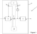
- Fig. 1 illustrates schematically a portable sample preparation device 1 according to the invention, in a simple form.
- the portable sample preparation device 1 comprises a housing 3, of any convenient configuration, which serves to contain the portable sample preparation device 1.
- a collecting chamber 5 into which a sample may be introduced via input 5i.
- the sample may be injected, pumped, suctioned, or introduced into collecting chamber 5 in any convenient manner, and a valve may be provided upstream of input 5i if required.
- Collecting chamber 5 comprises an output 5o, which is in operative connection with an input 7i of extraction device 7 via controllable first valve 9. In other words, output 5o is in selective fluid communication with input 7i.
- samples may be considered, whether solid (dissolved in an appropriate solvent), or liquid, or even solutions of gases in a liquid solute.
- samples are water (sea water, river water, lake water, drinking water, waste water, swimming pool water), body samples (e.g. bodily fluids such as blood, urine, saliva, and tissues such as skin), or food products (e.g. fruit juice, milk cereals, meat, fruits, beer wort, beer, wine must, wine, spirits and so on).
- Extraction device 7 furthermore comprises an output 7o, for outputting a prepared sample, for instance to a sensor (which may be internal or external to the device 1), or to a collection vessel for later analysis.
- a sensor which may be internal or external to the device 1.
- a source of pressurised gas or liquid 11 such as an air pump, a gas canister, an input line from an external gas canister or from an external gas pump, or similar in the case of pressurised gas, or in the case of a pressurised liquid, this liquid should preferably be immiscible with the other liquids in the system with which they will come into contact, and can be pressurised e.g. by means of a pump.
- pressurised gas In the present and following examples, reference is made to pressurised gas, however the changes required to use pressurised liquid are clear.
- This source of pressurised gas or liquid 11 serves to propel liquids through the various components of the portable sample preparation device 1 by displacement, as will become clearer below.
- one or more pumps may be used to directly move the various liquids through the system.
- Source of pressurised gas 11 is in operative connection with both a solvent reservoir 13 and the sample chamber 5, via respectively a second valve 17, and an optional third valve 15, so as to be able to force a sample out of the collecting chamber 5, and to force solvent into the input 7i of extraction device 7.
- Optional third valve 15 can be omitted, in which case the sample chamber 5 is in constant fluid communication with the source of pressurised gas 11.
- Valves 9, 15 and 17 are controlled by controller 19 so as to create the correct flows of fluids and gases through the system, and it should be noted that dashed lines represent connections between controller 19 and other components.
- Extraction device 7 may be of any convenient type, particularly one of the following types:
- these particles may be magnetic such that they can be moved with an integrated and/or external magnetic field during the sample preparation process.
- an appropriate solvent is provided in solvent reservoir 13, and if required a supply of a buffer liquid or solution, such as saline solution or (distilled or deionised) water, can be provided as appropriate.
- a buffer liquid or solution such as saline solution or (distilled or deionised) water
- thermo-sensitive media is a hydrogel which is hydrophobic at higher temperatures, and is hydrophilic at lower temperatures. At higher temperatures, the hydrophobic hydrogel will thus absorb apolar, non-ionic substances from a sample.
- the concentrated sample can either be passed directly to a sensor, or can be stored in an appropriate format, such as concentrated in a buffer, in Eppendorf-format tubes, or similar. If stored in this way the concentrated sample can then be analysed in a laboratory.
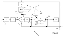
- Figure 2 illustrates a particular embodiment of a portable sample preparation device 1 according to the invention, adapted for in-situ detection of both estrogenic compounds and poly-aromatic hydrocarbons.
- the portable sample preparation device 1 comprises a housing 3, which contains, as before, a collecting chamber 5, a source of pressurised gas 11, an extraction device 7, and a controller 19. So as not to overcharge the figure, the connections between the controller 19, pressure controller 29, and the various valves 15, 17, 23, 33, 41, 43, 49, 55 have not been shown.
- source of pressurised gas 11 is a pump, which compresses ambient air in a pressure chamber 25, which is provided with a pressure sensor 27 operatively connected with the controller 19.
- Pressure chamber 25 outputs through pressure controller 29, which is likewise operatively connected with the controller 19.
- a macrofilter 21 Upstream of collecting chamber 5 is a macrofilter 21 through which the sample passes after having been introduced through sample inlet 22, so as to avoid undesirable particles entering the system, such as small particles and/or small organisms with an average diameter above 0.1 ⁇ m. If the sample is solid and is required to be in liquid form, it may have been dissolved in a solvent such as water prior to passing through macrofilter 21.
- Collecting chamber 5 outputs via valve 23 (fulfilling a similar function to first valve 9 of figure 1 ) to a collected sample reservoir 31, under pressure from pressure chamber 25.
- Sample reservoir 31 is furthermore in operative connection with pressure chamber 25, so as to be able to displace a collected sample from the sample reservoir 31.
- collecting chamber 5 and collected sample reservoir 31 do not need to be separate chambers, and can be replaced by a single chamber.
- the other adjustments to the system to achieve this configuration do not need to be elaborated upon here.
- An example of this type of configuration is given in the embodiment of figure 4 (see below).
- the collected sample reservoir 31 can be drained through valve 33, from where it exits the housing at sample / waste outlet 35. It should also be noted that valve 37 permits venting the line between the pressure chamber 25 and the sample reservoir 31 to atmosphere.
- degassing device 39 Downstream of collected sample reservoir 31 is a degassing device 39, arranged so as to remove any bubbles which may be present in the collected sample. If not required, degassing device 39 can be omitted. Alternatively, one or more degassing devices 39 can be placed at one or more different positions in the system, as required. Similarly to valve 33, valve 41 permits to drain the downstream side of degassing device 39.
- extraction device 7 comprises a first solid phase extraction column 7a for polyaromatic hydrocarbons, for which is provided a first reservoir 45 containing an appropriate solvent, together with a second solid phase extraction column 7b for estrogenic compounds, likewise together with a second reservoir 47 likewise containing an appropriate solvent.
- both columns 7a, 7b are filled with octadecyl-coated silica particles.
- First and second reservoirs 45, 47 are both operatively connected with the source of pressurised gas 11 via valve 17, as in the example of figure 1 , so as to, when required, displace solvent from the reservoirs 45, 47 and force it through the respective columns 7a, 7b.
- a three-way valve 49 Downstream of the extraction columns 7a, 7b is provided a three-way valve 49, arranged so as to selectively connect the outputs of the extraction columns 7a, 7b to the sensor 51, or to the sample / waste outlet 35. In such a fashion, the concentrated portion of the sample can be passed to the sensor, and the diluted portion can be simply output.
- a saline solution reservoir 53 is provided upstream of sensor 51, so as to provide a buffer solution and to flush the sensor and the line leading from the three-way valve 49 to the sample / waste outlet 35.
- saline solution reservoir 53 is selectively in operative connection with the source of pressurised gas 11 via valve 55 so as to permit this.
- check valves (illustrated as large black arrows pointing in the direction of flow) can be arranged as appropriate to prevent backflow of liquids and gases. Naturally, further check valves may be added, and any which are not strictly necessary can be omitted or replaced by normal valves.
- the controller After introduction of a sample at sample input 22, the controller opens and closes the various valves at the appropriate moments and for the appropriate lengths of time so as to move the sample through the portable sample preparation device 1, to concentrate the species of interest in the extraction device 7, and to pass the concentrated sample to the sensor while outputting the remainder of the sample and the accompanying solvents at the sample / waste output 35.
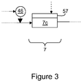
- FIG 3 illustrates schematically a variant of extraction device 7.
- extraction device 7 comprises a microfluidic chip 7c containing a thermo-sensitive hydrogel, as discussed above.
- Other elements of the portable sample preparation device have been omitted, and it should be understood that extraction device 7 of figure 3 may simply replace that of figure 2 in the portable sample preparation device 1 of that figure.
- a heating and/or cooling device 57 is provided so as to heat and/or cool microfluidic chip 7c in response to signals from the controller 19 (the connection to which is represented by the dashed arrow in this figure).
- Solvent reservoir 46 is identical to solvent reservoir 45 in figure 2 , yet contains water, which allows organic-solvent-free preparation of an aqueous sample. Hence, a desired organic compound can be extracted by the gel at a temperature above its critical solution temperature (LCST), and be released into water at a temperature below this LCST.
- LCST critical solution temperature
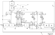
- Figure 4 illustrates a further embodiment of a portable automated sample preparation device 1 according to the invention.
- the portable sample preparation device 1 comprises a housing 3, which contains, as before, a collecting chamber 5, a source of pressurised gas 11, an extraction device 7, which may be any of the above-mentioned types, and a controller 19. So as not to overcharge the figure, the connections between the controller 19, pressure controller 29, and all the various valves 30, 61, 15, 77, 79, 81, 83, 85, 87, 89, 91, 93, 95, 97, 99, 101, 109, 111, 113, 115, 117, 119, 121, 127, 129, 131, 135 (see below) have not been shown.
- source of pressurised gas 11 is a pump, which compresses ambient air in a pressure chamber 25, which is provided with a pressure sensor 27 operatively connected with the controller 19.
- Pressure chamber 25 outputs through pressure controller 29, which is likewise operatively connected with the controller 19, and can be vented to the outside of the housing 3 via valve 30.
- upstream of collecting chamber 5 is a macrofilter 21 through which the sample passes after having been introduced through sample inlet 22, so as to avoid large undesirable particles entering the system, such as small particles and/or small organisms with an average diameter above 0.1 ⁇ m. If the sample is solid and is required to be in liquid form, it may have been dissolved in a solvent such as water prior to passing through macrofilter 21.
- Collecting chamber 5 can be vented to the exterior of the housing 3 via valve so as to be purged.
- collecting chamber 5 is in operative connection with pressure chamber 25 via a valve 15 (corresponding to valve 15 of figure 1 ), so as to be able to displace fluid from collecting chamber 5 by gas pressure.
- valve 15 corresponding to valve 15 of figure 1
- Collecting chamber 5 is in operative connection with extraction device 7 via valve 65 (corresponding to valve 9 of figure 1 ), and downstream of valve 65 and upstream of extraction device 7 are provided a plurality of solvent reservoirs 67, 69, 71 and 73, which contain different solvents for operating the extraction device 7.
- reservoir 67 may contain a conditioning solvent (such as dilute acetic acid)
- reservoir 69 may contain a washing solvent (such as methanol diluted in water)
- reservoir 71 may contain a regeneration solvent (such as methanol, preferably substantially 100% methanol)
- reservoir 73 may contain an elution solvent (such as methanol).
- Each reservoir 67, 69, 71, 73 is provided with a corresponding upstream valve 77, 79, 81, 83 respectively, and downstream valve 87, 89, 91, 93 respectively.
- an intermediate reservoir 75 is provided upstream of valve 93 and downstream of reservoir 73, with a further valve 95 being situated between intermediate reservoir 75 and reservoir 73.
- This intermediate reservoir 75 can be fully charged with a predetermined quantity of eluent solvent from reservoir 73, corresponding to the volume of intermediate reservoir 75, which can then be discharged through the separation device 7 via valve 93 by means of gas pressure from the pressure chamber 25, supplied via valve 85.
- a yet further valve 97 is provided, which permits the gas within the intermediate reservoir 75 to escape to sample / waste outlet 35, and be replaced with eluent.
- valve 99 Downstream of separation device 7, valve 99 leads to sample / waste outlet 35, so as to permit draining or purging the separation device 7. Also downstream of separation device 7 is a further valve 101 connecting the separation device 7 with an incubation chamber 103. Incubation chamber 103 is used to carry out a chemical reaction on the concentrated sample leaving the separation device 7, by means of a buffer solution contained within buffer reservoir 105 and a reactant contained within reactant reservoir 107. Each of these reservoirs is connected upstream to the pressure chamber 25 via valves 109 and 111 respectively, and downstream to the incubation chamber 103 via valves 113 and 115 respectively. Incubation chamber 103 itself is also connected upstream to the pressure chamber 25 via valve 119, and downstream to the sample / waste outlet 35 via valve 117.
- Valves 93, 101, 109, 113, 111, 115 and 117 are opened so as to flow the sample out of the separator device 7 into the incubation chamber 103.
- valve 117 is closed, the reaction takes place for a predetermined length of time, and subsequently the reacted sample leaves downstream via valve 121, which leads to optional degassing device 39 which is in fluid communication with the sensor 51. Note that, if no reaction needs take place, incubation chamber 103 and the associated reservoirs and valves can be omitted, or the sample can be simply passed through the incubation chamber 103 without application of buffer solution or reactant.
- regeneration reservoir 123 Downstream of valve 121 and upstream of the degassing device 29 are situated two further reservoirs, namely regeneration reservoir 123, containing a regeneration liquid for flushing and regenerating the sensor 51, and a further buffer reservoir 125.
- Each of these reservoirs 123, 125 is connected upstream to the pressure chamber 25 via valves 127, 129 respectively, and downstream to the gas bubble trap 39 via valves 131 and 135 respectively.
- a sample introduced into the system at sample inlet 22 can be made to move through the system, have the one or more species of interest concentrated by the extraction device 7, be reacted if required in the incubation chamber 103, and sensed by the sensor 51.
- This is carried out by the controller 19 opening and closing all the various valves 30, 61, 15, 77, 79, 81, 83, 85, 87, 89, 91, 93, 95, 97, 99, 101, 109, 111, 113, 115, 117, 119, 121, 127, 129, 131, 135 in an appropriate sequence and at appropriate times.
- These substances can be either detected immediately in a sensor provided in the sample preparation device (1), or the samples can be simply concentrated and prepared e.g. in a sample tube for later detection in the lab or by a sensor situated in a different system.
Landscapes
- Physics & Mathematics (AREA)
- Health & Medical Sciences (AREA)
- Life Sciences & Earth Sciences (AREA)
- Chemical & Material Sciences (AREA)
- Analytical Chemistry (AREA)
- Biochemistry (AREA)
- General Health & Medical Sciences (AREA)
- General Physics & Mathematics (AREA)
- Immunology (AREA)
- Pathology (AREA)
- Sampling And Sample Adjustment (AREA)
Claims (15)
- Tragbare automatisierte Probenherstellungsvorrichtung (1), enthaltend:- eine Sammelkammer (5) zur Aufnahme einer Probe;- mindestens eine Extraktionsvorrichtung (7; 7a, 7b), umfassend eine Eingabe (7i) in operativer Verbindung mit einer Ausgabe (5o) der Sammelkammer und umfassend eine Ausgabe (7o) zum Ausgeben einer konzentrierten Probe;- einen Lösemittelbehälter (13; 45, 47; 67, 69, 71, 73), der ausgelegt ist, um Lösemittel zu enthalten, wobei der Lösemittelbehälter (13; 45, 47; 67, 69, 71, 73) in operativer Verbindung mit der Eingabe (7i) der Extraktionsvorrichtung steht,- eine Quelle von unter Druck stehendem Gas oder unter Druck stehender Flüssigkeit (11) in operativer Verbindung mit der Sammelkammer (5) und mit dem Lösemittelbehälter (13; 45, 47; 67, 69, 71, 73) und angeordnet, um zu verursachen, dass die Probe und das Lösemittel durch die Extraktionsvorrichtung (7; 7a, 7b) passieren;wobei die Probenherstellungsvorrichtung (1) dadurch gekennzeichnet ist, dass die Sammelkammer (5), die mindestens eine Extraktionsvorrichtung (7; 7a, 7b), der Lösemittelbehälter (13; 45, 47; 67, 69, 71, 73) und die Quelle von unter Druck stehendem Gas oder unter Druck stehender Flüssigkeit (11) in einem Gehäuse (3) enthalten sind, und weiter dadurch gekennzeichnet, dass das Gehäuse (3) ein erstes Ventil (9; 23; 43; 65) in fluidischer Kommunikation mit jedem der Sammelkammer (5) und der Extraktionsvorrichtung (7) umfasst;- ein zweites Ventil (17; 77, 79, 81, 83) in fluidischer Kommunikation mit jedem der Quelle (11) von unter Druck stehendem Gas oder unter Druck stehender Flüssigkeit und dem Lösemittelbehälter (13);- eine Steuerung (19), die ausgelegt ist, um den Betrieb der Probenherstellungsvorrichtung (1) zu steuern.
- Tragbare automatisierte Probenherstellungsvorrichtung (1) nach dem vorhergehenden Anspruch, weiter umfassen dein drittes Ventil (15) in fluidischer Kommunikation mit jedem der Quelle von unter Druck stehendem Gas oder unter Druck stehender Flüssigkeit (11) und der Sammelkammer, wobei das Ventil (15) dazu ausgelegt ist, von der Steuerung (19) gesteuert zu werden.
- Tragbare automatisierte Probenherstellungsvorrichtung (1) nach einem der vorhergehenden Ansprüche, weiter umfassend einen Filter (21), der vorgelagert von der Sammelkammer (5) und in fluidischer Kommunikation mit der Sammelkammer (5) angeordnet ist.
- Tragbare automatisierte Probenherstellungsvorrichtung (1) nach einem der vorhergehenden Ansprüche, weiter umfassend eine Entgasungsvorrichtung (39) in fluidischer Kommunikation mit einer Ausgabe der Sammelkammer (5) und der Eingabe der Extraktionsvorrichtung (7; 7a, 7b).
- Tragbare automatisierte Probenherstellungsvorrichtung (1) nach dem vorhergehenden Anspruch, weiter umfassen deinen Probebehälter (31), der nachgelagert von der Sammelkammer (5) und vorgelagert von der Entgasungsvorrichtung (39) angeordnet ist.
- Tragbare automatisierte Probenherstellungsvorrichtung (1) nach einem der vorhergehenden Ansprüche, wobei die Extraktionsvorrichtung (7; 7a, 7b) mindestens eines der Folgenden umfasst:- unbeschichtete Partikel;- beschichtete Partikel;- Mikropartikel, umfassend eine wämeempfindliche Polymerbeschichtung darauf;- ein Stimulus-empfindliche Hydrogel wie z. B. ein wärmeempfindliches Hydrogel;- ein Hydrogel;- eine monolithische feste Phase;- eine Membran.
- Tragbare automatisierte Probenherstellungsvorrichtung (1) nach einem der vorhergehenden Ansprüche, weiter umfassend einen Sensor (51) in operativer Verbindung mit der Extraktionsvorrichtung (7; 7a, 7b).
- Tragbare automatisierte Probenherstellungsvorrichtung (1) nach dem vorhergehenden Anspruch, wobei die mindestens eine Extraktionsvorrichtung (7; 7a, 7b) eine Vielzahl von Extraktionsvorrichtungen (7a; 7b) umfasst, von denen jede ausgelegt ist, um eine bestimmte Substanz oder eine bestimmte Klasse von Substanzen zu konzentrieren.
- Tragbare automatisierte Probenherstellungsvorrichtung (1) nach einem der vorhergehenden Ansprüche, weiter umfassen deine Inkubationskammer (103), die nachgelagert von der Extraktionsvorrichtung (7) und in fluidischer Kommunikation mit mindestens einem eines Pufferbehälters (105) und eines Reaktantbehälters (107) steht.
- Verfahren zur Herstellung einer Probe mit Hilfe einer tragbaren automatisierten Probenherstellungsvorrichtung (1) nach einem der vorhergehenden Ansprüche, umfassend die folgenden Schritte:- Aufnehmen einer Probe in einer Sammelkammer (5);- Anwenden eines Drucks mit Hilfe des unter Druck stehenden Gases oder der unter Druck stehenden Flüssigkeit auf die Sammelkammer (5), um zu verursachen, dass die Probe in die Extraktionsvorrichtung (7; 7a, 7b) durch ein erstes Ventil (9; 23; 43; 65) passiert, das in fluidischer Kommunikation mit jedem der Sammelkammer (5) und der Extraktionsvorrichtung (7; 7a, 7b) steht;- Konzentrieren der Probe in der Extraktionsvorrichtung (7; 7a, 7b);- Anwenden eines Drucks mit Hilfe des unter Druck stehenden Gases oder der unter Druck stehenden Flüssigkeit auf die Sammelkammer (13; 45, 47), um die Probe aus der Extraktionsvorrichtung (7; 7a, 7b) in konzentrierter Form durch ein zweites Ventil (17; 77, 79, 81, 83) in fluidischer Kommunikation mit jedem der Quelle (11) von unter Druck stehendem Gas oder unter Druck stehender Flüssigkeit und dem Lösemittelbehälter (13) auszustoßen;wobei die Schritte mit Hilfe einer Steuerung (19) gesteuert werden.
- Verfahren nach Anspruch 10, wobei die Steuerung (19) selektiv die Öffnung und den Verschluss des ersten Ventils (9; 23, 43; 65), des zweiten Ventils (17; 77, 79, 81, 83) und des optionalen dritten Ventils (15), falls vorhanden, steuert.
- Verfahren nach einem der Ansprüche 10 und 11, weiter umfassend einen Schritt des Filterns der Probe, bevor sie in der Sammelkammer (5) aufgenommen wird.
- Verfahren nach einem der Ansprüche 10 - 12, weiter umfassend einen Schritt des Entfernens von Gas von der Probe, bevor sie in die Extraktionsvorrichtung (7; 7a, 7b) eingeführt wird.
- Verfahren nach einem der Ansprüche 10 - 13, wobei die Probe in der Extraktionsvorrichtung (7; 7a, 7b) mit Hilfe einer Festphasenextraktion oder molekular geprägter Polymere oder eines Stimulus-empfindlichen Hydrogels wie z. B. eines wärmeempfindlichen Hydrogels oder einer Stimulus-empfindlichen Polymerbeschichtung wie z. B. einer wärmeempfindlichen Polymerbeschichtung auf Mikropartikeln oder einer monolithischen Phase oder eines einfachen Hydrogels oder einer Membran konzentriert wird.
- Verfahren nach einem der Ansprüche 10 - 14, weiter umfassend einen Schritt des Nachweisens einer bestimmten Substanz mit Hilfe eines Sensors (51).
Priority Applications (2)
| Application Number | Priority Date | Filing Date | Title |
|---|---|---|---|
| EP14169774.8A EP2950076B1 (de) | 2014-05-26 | 2014-05-26 | Tragbares System zur automatischen Vorbereitung flüssiger und/oder fester Proben |
| US14/720,857 US20150338323A1 (en) | 2014-05-26 | 2015-05-25 | Portable system for automated preparation of liquid and/or solid samples |
Applications Claiming Priority (1)
| Application Number | Priority Date | Filing Date | Title |
|---|---|---|---|
| EP14169774.8A EP2950076B1 (de) | 2014-05-26 | 2014-05-26 | Tragbares System zur automatischen Vorbereitung flüssiger und/oder fester Proben |
Publications (2)
| Publication Number | Publication Date |
|---|---|
| EP2950076A1 EP2950076A1 (de) | 2015-12-02 |
| EP2950076B1 true EP2950076B1 (de) | 2017-06-28 |
Family
ID=50774712
Family Applications (1)
| Application Number | Title | Priority Date | Filing Date |
|---|---|---|---|
| EP14169774.8A Not-in-force EP2950076B1 (de) | 2014-05-26 | 2014-05-26 | Tragbares System zur automatischen Vorbereitung flüssiger und/oder fester Proben |
Country Status (2)
| Country | Link |
|---|---|
| US (1) | US20150338323A1 (de) |
| EP (1) | EP2950076B1 (de) |
Families Citing this family (7)
| Publication number | Priority date | Publication date | Assignee | Title |
|---|---|---|---|---|
| CN105547753B (zh) * | 2016-01-26 | 2018-02-02 | 安徽工业大学 | 生物污泥原态采样器及使用方法 |
| DE102016007094B3 (de) * | 2016-06-10 | 2016-12-22 | Qfood Gmbh | Probenentnahmevorrichtung zur Entnahme von Getränkeproben aus einer Getränkeleitung, die ein unter Druck stehendes gashaltiges Getränk enthält |
| US10557104B2 (en) * | 2017-12-19 | 2020-02-11 | Botanex Intelletual Property LLC | Modular, mobile, and automated solvent extraction and distillation systems, and methods of using the same |
| US12338411B2 (en) * | 2017-12-19 | 2025-06-24 | Botanex Intellectual Property LLC | Modular, mobile, and automated solvent extraction and distillation systems, and methods of using the same |
| CN110514500A (zh) * | 2019-09-24 | 2019-11-29 | 江苏中朗宏泰科学仪器有限公司 | 一种高通量全自动样品前处理仪、应用及使用方法 |
| CN111442966A (zh) * | 2020-04-08 | 2020-07-24 | 山东省科学院海洋仪器仪表研究所 | 海水中有机污染物原位萃取富集采样装置及方法 |
| CN114002046A (zh) * | 2021-10-11 | 2022-02-01 | 中国原子能科学研究院 | 制源装置 |
Family Cites Families (15)
| Publication number | Priority date | Publication date | Assignee | Title |
|---|---|---|---|---|
| US4942135A (en) * | 1986-08-04 | 1990-07-17 | The United States Of America As Represented By The United States Department Of Energy | Method for preconcentrating a sample for subsequent analysis |
| US6306350B1 (en) * | 1999-05-19 | 2001-10-23 | Itt Manufacturing Enterprises, Inc. | Water sampling method and apparatus with analyte integration |
| US7169599B2 (en) * | 2003-06-20 | 2007-01-30 | Groton Biosystems, Llc | Fluid interface for bioprocessor systems |
| US7601545B2 (en) * | 2003-06-20 | 2009-10-13 | Groton Biosystems, Llc | Automated macromolecule sample preparation system |
| US20050019951A1 (en) * | 2003-07-14 | 2005-01-27 | Gjerde Douglas T. | Method and device for extracting an analyte |
| ES2692380T3 (es) * | 2006-03-24 | 2018-12-03 | Handylab, Inc. | Método para realizar PCR con un cartucho con varias pistas |
| CN101067621B (zh) | 2007-06-05 | 2010-07-21 | 中国科学院上海微系统与信息技术研究所 | 一种基于微加工方法制作的微型固相萃取芯片及使用方法 |
| CN201096675Y (zh) | 2007-11-06 | 2008-08-06 | 河南理工大学 | 连续流动-固相微萃取装置 |
| KR20110030415A (ko) * | 2008-01-22 | 2011-03-23 | 인터젠엑스 인크. | 만능 샘플 제조 시스템 및 집적 분석 시스템에서의 용도 |
| US8133451B2 (en) * | 2008-08-28 | 2012-03-13 | Microfluidic Systems, Inc. | Sample preparation apparatus |
| US8337705B2 (en) * | 2008-12-04 | 2012-12-25 | Roche Diagnostics Operations, Inc. | Manipulation of magnetic microparticles in a high pressure liquid system and extraction process |
| IN2012DN03430A (de) * | 2009-09-21 | 2015-10-23 | Akonni Biosystems | |
| DE102009043227A1 (de) | 2009-09-28 | 2011-03-31 | Siemens Aktiengesellschaft | Verfahren zur automatisierten Vorbereitung von Proben für ein Biosensor-System und Vorrichtung zu dessen Durchführung |
| CN101690855B (zh) | 2009-10-12 | 2012-04-18 | 中国检验检疫科学研究院 | 集成固相微萃取的微流控芯片以及检测方法 |
| US9440166B2 (en) * | 2012-08-30 | 2016-09-13 | Dionex Corporation | Method and device to extract an analyte from a sample with gas assistance |
-
2014
- 2014-05-26 EP EP14169774.8A patent/EP2950076B1/de not_active Not-in-force
-
2015
- 2015-05-25 US US14/720,857 patent/US20150338323A1/en not_active Abandoned
Also Published As
| Publication number | Publication date |
|---|---|
| EP2950076A1 (de) | 2015-12-02 |
| US20150338323A1 (en) | 2015-11-26 |
Similar Documents
| Publication | Publication Date | Title |
|---|---|---|
| EP2950076B1 (de) | Tragbares System zur automatischen Vorbereitung flüssiger und/oder fester Proben | |
| US20240353439A1 (en) | Fluidic bridge device and sample processing methods | |
| US20210208032A1 (en) | Liquid to Liquid Biological Particle Concentrator with Disposable Fluid Path | |
| US8937174B2 (en) | Method and device for the automated processing of a sample | |
| CA2940870C (en) | Liquid to liquid biological particle concentrator with disposable fluid path | |
| JP2007519917A5 (de) | ||
| JP2009533048A (ja) | 貫流セルのための抑泡薄膜 | |
| Sae-Khow et al. | Pervaporation in chemical analysis | |
| US20260070050A1 (en) | Liquid to liquid biological particle concentrator with disposable fluid path | |
| CN111386459B (zh) | 用于制备用于气相色谱仪的液体样品的设备 | |
| US20160320354A1 (en) | Device for extracting a volatile component | |
| CN118159843A (zh) | 用于自主确定液体样本中的挥发性标记物的浓度的气相色谱仪 | |
| CN1382969A (zh) | 基于膜萃取技术的天然水中污染物现场采样装置 | |
| Kinahan et al. | Centrifugally automated Solid-Phase Extraction of DNA by immiscible liquid valving and chemically powered centripetal pumping of peripherally stored reagents | |
| JP7115239B2 (ja) | 分析装置及び該分析装置に用いられる濃縮装置 | |
| CN105688442B (zh) | 一种柱层析与膜过滤集成系统 | |
| JP2020500550A (ja) | 粒子を隔離するためのマイクロ流体装置とマイクロ流体システムと方法 | |
| JP2007155398A (ja) | 濃縮素子、及び、それを用いた化学分析装置 | |
| US12480842B2 (en) | Liquid to liquid biological particle concentrator with disposable fluid path | |
| Karlsson et al. | On-chip liquid degassing with low water loss | |
| HK40081265A (en) | Liquid to liquid biological particle concentrator with disposable fluid path | |
| Lécluse et al. | Embedding off-the-shelf filter in PDMS chip for microbe sampling | |
| CN108802247A (zh) | 一种膜辅助三液相萃取方法 |
Legal Events
| Date | Code | Title | Description |
|---|---|---|---|
| AK | Designated contracting states |
Kind code of ref document: A1 Designated state(s): AL AT BE BG CH CY CZ DE DK EE ES FI FR GB GR HR HU IE IS IT LI LT LU LV MC MK MT NL NO PL PT RO RS SE SI SK SM TR |
|
| AX | Request for extension of the european patent |
Extension state: BA ME |
|
| PUAI | Public reference made under article 153(3) epc to a published international application that has entered the european phase |
Free format text: ORIGINAL CODE: 0009012 |
|
| RIN1 | Information on inventor provided before grant (corrected) |
Inventor name: HEUB, SARAH |
|
| 17P | Request for examination filed |
Effective date: 20160406 |
|
| RBV | Designated contracting states (corrected) |
Designated state(s): AL AT BE BG CH CY CZ DE DK EE ES FI FR GB GR HR HU IE IS IT LI LT LU LV MC MK MT NL NO PL PT RO RS SE SI SK SM TR |
|
| GRAP | Despatch of communication of intention to grant a patent |
Free format text: ORIGINAL CODE: EPIDOSNIGR1 |
|
| INTG | Intention to grant announced |
Effective date: 20170110 |
|
| GRAS | Grant fee paid |
Free format text: ORIGINAL CODE: EPIDOSNIGR3 |
|
| GRAA | (expected) grant |
Free format text: ORIGINAL CODE: 0009210 |
|
| AK | Designated contracting states |
Kind code of ref document: B1 Designated state(s): AL AT BE BG CH CY CZ DE DK EE ES FI FR GB GR HR HU IE IS IT LI LT LU LV MC MK MT NL NO PL PT RO RS SE SI SK SM TR |
|
| REG | Reference to a national code |
Ref country code: GB Ref legal event code: FG4D |
|
| REG | Reference to a national code |
Ref country code: CH Ref legal event code: EP |
|
| REG | Reference to a national code |
Ref country code: AT Ref legal event code: REF Ref document number: 905302 Country of ref document: AT Kind code of ref document: T Effective date: 20170715 |
|
| REG | Reference to a national code |
Ref country code: IE Ref legal event code: FG4D |
|
| REG | Reference to a national code |
Ref country code: DE Ref legal event code: R096 Ref document number: 602014011145 Country of ref document: DE |
|
| REG | Reference to a national code |
Ref country code: CH Ref legal event code: NV Representative=s name: NOVAGRAAF INTERNATIONAL SA, CH |
|
| PG25 | Lapsed in a contracting state [announced via postgrant information from national office to epo] |
Ref country code: GR Free format text: LAPSE BECAUSE OF FAILURE TO SUBMIT A TRANSLATION OF THE DESCRIPTION OR TO PAY THE FEE WITHIN THE PRESCRIBED TIME-LIMIT Effective date: 20170929 Ref country code: HR Free format text: LAPSE BECAUSE OF FAILURE TO SUBMIT A TRANSLATION OF THE DESCRIPTION OR TO PAY THE FEE WITHIN THE PRESCRIBED TIME-LIMIT Effective date: 20170628 Ref country code: FI Free format text: LAPSE BECAUSE OF FAILURE TO SUBMIT A TRANSLATION OF THE DESCRIPTION OR TO PAY THE FEE WITHIN THE PRESCRIBED TIME-LIMIT Effective date: 20170628 Ref country code: LT Free format text: LAPSE BECAUSE OF FAILURE TO SUBMIT A TRANSLATION OF THE DESCRIPTION OR TO PAY THE FEE WITHIN THE PRESCRIBED TIME-LIMIT Effective date: 20170628 Ref country code: NO Free format text: LAPSE BECAUSE OF FAILURE TO SUBMIT A TRANSLATION OF THE DESCRIPTION OR TO PAY THE FEE WITHIN THE PRESCRIBED TIME-LIMIT Effective date: 20170928 |
|
| REG | Reference to a national code |
Ref country code: NL Ref legal event code: MP Effective date: 20170628 |
|
| REG | Reference to a national code |
Ref country code: LT Ref legal event code: MG4D |
|
| REG | Reference to a national code |
Ref country code: AT Ref legal event code: MK05 Ref document number: 905302 Country of ref document: AT Kind code of ref document: T Effective date: 20170628 |
|
| PG25 | Lapsed in a contracting state [announced via postgrant information from national office to epo] |
Ref country code: SE Free format text: LAPSE BECAUSE OF FAILURE TO SUBMIT A TRANSLATION OF THE DESCRIPTION OR TO PAY THE FEE WITHIN THE PRESCRIBED TIME-LIMIT Effective date: 20170628 Ref country code: LV Free format text: LAPSE BECAUSE OF FAILURE TO SUBMIT A TRANSLATION OF THE DESCRIPTION OR TO PAY THE FEE WITHIN THE PRESCRIBED TIME-LIMIT Effective date: 20170628 Ref country code: RS Free format text: LAPSE BECAUSE OF FAILURE TO SUBMIT A TRANSLATION OF THE DESCRIPTION OR TO PAY THE FEE WITHIN THE PRESCRIBED TIME-LIMIT Effective date: 20170628 Ref country code: NL Free format text: LAPSE BECAUSE OF FAILURE TO SUBMIT A TRANSLATION OF THE DESCRIPTION OR TO PAY THE FEE WITHIN THE PRESCRIBED TIME-LIMIT Effective date: 20170628 Ref country code: BG Free format text: LAPSE BECAUSE OF FAILURE TO SUBMIT A TRANSLATION OF THE DESCRIPTION OR TO PAY THE FEE WITHIN THE PRESCRIBED TIME-LIMIT Effective date: 20170928 |
|
| PG25 | Lapsed in a contracting state [announced via postgrant information from national office to epo] |
Ref country code: EE Free format text: LAPSE BECAUSE OF FAILURE TO SUBMIT A TRANSLATION OF THE DESCRIPTION OR TO PAY THE FEE WITHIN THE PRESCRIBED TIME-LIMIT Effective date: 20170628 Ref country code: SK Free format text: LAPSE BECAUSE OF FAILURE TO SUBMIT A TRANSLATION OF THE DESCRIPTION OR TO PAY THE FEE WITHIN THE PRESCRIBED TIME-LIMIT Effective date: 20170628 Ref country code: RO Free format text: LAPSE BECAUSE OF FAILURE TO SUBMIT A TRANSLATION OF THE DESCRIPTION OR TO PAY THE FEE WITHIN THE PRESCRIBED TIME-LIMIT Effective date: 20170628 Ref country code: AT Free format text: LAPSE BECAUSE OF FAILURE TO SUBMIT A TRANSLATION OF THE DESCRIPTION OR TO PAY THE FEE WITHIN THE PRESCRIBED TIME-LIMIT Effective date: 20170628 Ref country code: CZ Free format text: LAPSE BECAUSE OF FAILURE TO SUBMIT A TRANSLATION OF THE DESCRIPTION OR TO PAY THE FEE WITHIN THE PRESCRIBED TIME-LIMIT Effective date: 20170628 |
|
| PG25 | Lapsed in a contracting state [announced via postgrant information from national office to epo] |
Ref country code: IT Free format text: LAPSE BECAUSE OF FAILURE TO SUBMIT A TRANSLATION OF THE DESCRIPTION OR TO PAY THE FEE WITHIN THE PRESCRIBED TIME-LIMIT Effective date: 20170628 Ref country code: SM Free format text: LAPSE BECAUSE OF FAILURE TO SUBMIT A TRANSLATION OF THE DESCRIPTION OR TO PAY THE FEE WITHIN THE PRESCRIBED TIME-LIMIT Effective date: 20170628 Ref country code: IS Free format text: LAPSE BECAUSE OF FAILURE TO SUBMIT A TRANSLATION OF THE DESCRIPTION OR TO PAY THE FEE WITHIN THE PRESCRIBED TIME-LIMIT Effective date: 20171028 Ref country code: PL Free format text: LAPSE BECAUSE OF FAILURE TO SUBMIT A TRANSLATION OF THE DESCRIPTION OR TO PAY THE FEE WITHIN THE PRESCRIBED TIME-LIMIT Effective date: 20170628 Ref country code: ES Free format text: LAPSE BECAUSE OF FAILURE TO SUBMIT A TRANSLATION OF THE DESCRIPTION OR TO PAY THE FEE WITHIN THE PRESCRIBED TIME-LIMIT Effective date: 20170628 |
|
| REG | Reference to a national code |
Ref country code: DE Ref legal event code: R097 Ref document number: 602014011145 Country of ref document: DE |
|
| PG25 | Lapsed in a contracting state [announced via postgrant information from national office to epo] |
Ref country code: DK Free format text: LAPSE BECAUSE OF FAILURE TO SUBMIT A TRANSLATION OF THE DESCRIPTION OR TO PAY THE FEE WITHIN THE PRESCRIBED TIME-LIMIT Effective date: 20170628 |
|
| PLBE | No opposition filed within time limit |
Free format text: ORIGINAL CODE: 0009261 |
|
| STAA | Information on the status of an ep patent application or granted ep patent |
Free format text: STATUS: NO OPPOSITION FILED WITHIN TIME LIMIT |
|
| REG | Reference to a national code |
Ref country code: FR Ref legal event code: PLFP Year of fee payment: 5 |
|
| 26N | No opposition filed |
Effective date: 20180329 |
|
| PG25 | Lapsed in a contracting state [announced via postgrant information from national office to epo] |
Ref country code: SI Free format text: LAPSE BECAUSE OF FAILURE TO SUBMIT A TRANSLATION OF THE DESCRIPTION OR TO PAY THE FEE WITHIN THE PRESCRIBED TIME-LIMIT Effective date: 20170628 |
|
| REG | Reference to a national code |
Ref country code: BE Ref legal event code: MM Effective date: 20180531 |
|
| PG25 | Lapsed in a contracting state [announced via postgrant information from national office to epo] |
Ref country code: MC Free format text: LAPSE BECAUSE OF FAILURE TO SUBMIT A TRANSLATION OF THE DESCRIPTION OR TO PAY THE FEE WITHIN THE PRESCRIBED TIME-LIMIT Effective date: 20170628 |
|
| REG | Reference to a national code |
Ref country code: IE Ref legal event code: MM4A |
|
| PG25 | Lapsed in a contracting state [announced via postgrant information from national office to epo] |
Ref country code: LU Free format text: LAPSE BECAUSE OF NON-PAYMENT OF DUE FEES Effective date: 20180526 |
|
| PG25 | Lapsed in a contracting state [announced via postgrant information from national office to epo] |
Ref country code: IE Free format text: LAPSE BECAUSE OF NON-PAYMENT OF DUE FEES Effective date: 20180526 |
|
| PG25 | Lapsed in a contracting state [announced via postgrant information from national office to epo] |
Ref country code: BE Free format text: LAPSE BECAUSE OF NON-PAYMENT OF DUE FEES Effective date: 20180531 |
|
| PG25 | Lapsed in a contracting state [announced via postgrant information from national office to epo] |
Ref country code: MT Free format text: LAPSE BECAUSE OF NON-PAYMENT OF DUE FEES Effective date: 20180526 |
|
| PG25 | Lapsed in a contracting state [announced via postgrant information from national office to epo] |
Ref country code: TR Free format text: LAPSE BECAUSE OF FAILURE TO SUBMIT A TRANSLATION OF THE DESCRIPTION OR TO PAY THE FEE WITHIN THE PRESCRIBED TIME-LIMIT Effective date: 20170628 |
|
| PG25 | Lapsed in a contracting state [announced via postgrant information from national office to epo] |
Ref country code: PT Free format text: LAPSE BECAUSE OF FAILURE TO SUBMIT A TRANSLATION OF THE DESCRIPTION OR TO PAY THE FEE WITHIN THE PRESCRIBED TIME-LIMIT Effective date: 20170628 |
|
| PG25 | Lapsed in a contracting state [announced via postgrant information from national office to epo] |
Ref country code: MK Free format text: LAPSE BECAUSE OF NON-PAYMENT OF DUE FEES Effective date: 20170628 Ref country code: HU Free format text: LAPSE BECAUSE OF FAILURE TO SUBMIT A TRANSLATION OF THE DESCRIPTION OR TO PAY THE FEE WITHIN THE PRESCRIBED TIME-LIMIT; INVALID AB INITIO Effective date: 20140526 Ref country code: CY Free format text: LAPSE BECAUSE OF FAILURE TO SUBMIT A TRANSLATION OF THE DESCRIPTION OR TO PAY THE FEE WITHIN THE PRESCRIBED TIME-LIMIT Effective date: 20170628 |
|
| PG25 | Lapsed in a contracting state [announced via postgrant information from national office to epo] |
Ref country code: AL Free format text: LAPSE BECAUSE OF FAILURE TO SUBMIT A TRANSLATION OF THE DESCRIPTION OR TO PAY THE FEE WITHIN THE PRESCRIBED TIME-LIMIT Effective date: 20170628 |
|
| PGFP | Annual fee paid to national office [announced via postgrant information from national office to epo] |
Ref country code: DE Payment date: 20200525 Year of fee payment: 7 Ref country code: FR Payment date: 20200527 Year of fee payment: 7 Ref country code: CH Payment date: 20200522 Year of fee payment: 7 |
|
| PGFP | Annual fee paid to national office [announced via postgrant information from national office to epo] |
Ref country code: GB Payment date: 20200522 Year of fee payment: 7 |
|
| REG | Reference to a national code |
Ref country code: DE Ref legal event code: R119 Ref document number: 602014011145 Country of ref document: DE |
|
| REG | Reference to a national code |
Ref country code: CH Ref legal event code: PL |
|
| GBPC | Gb: european patent ceased through non-payment of renewal fee |
Effective date: 20210526 |
|
| PG25 | Lapsed in a contracting state [announced via postgrant information from national office to epo] |
Ref country code: LI Free format text: LAPSE BECAUSE OF NON-PAYMENT OF DUE FEES Effective date: 20210531 Ref country code: CH Free format text: LAPSE BECAUSE OF NON-PAYMENT OF DUE FEES Effective date: 20210531 |
|
| PG25 | Lapsed in a contracting state [announced via postgrant information from national office to epo] |
Ref country code: GB Free format text: LAPSE BECAUSE OF NON-PAYMENT OF DUE FEES Effective date: 20210526 Ref country code: DE Free format text: LAPSE BECAUSE OF NON-PAYMENT OF DUE FEES Effective date: 20211201 |
|
| PG25 | Lapsed in a contracting state [announced via postgrant information from national office to epo] |
Ref country code: FR Free format text: LAPSE BECAUSE OF NON-PAYMENT OF DUE FEES Effective date: 20210531 |