EP2950115B1 - Capteur optoélectronique et procédé de détection d'objets - Google Patents
Capteur optoélectronique et procédé de détection d'objets Download PDFInfo
- Publication number
- EP2950115B1 EP2950115B1 EP15163302.1A EP15163302A EP2950115B1 EP 2950115 B1 EP2950115 B1 EP 2950115B1 EP 15163302 A EP15163302 A EP 15163302A EP 2950115 B1 EP2950115 B1 EP 2950115B1
- Authority
- EP
- European Patent Office
- Prior art keywords
- unit
- light
- data transmission
- optical
- sensor
- Prior art date
- Legal status (The legal status is an assumption and is not a legal conclusion. Google has not performed a legal analysis and makes no representation as to the accuracy of the status listed.)
- Active
Links
Images
Classifications
-
- G—PHYSICS
- G01—MEASURING; TESTING
- G01S—RADIO DIRECTION-FINDING; RADIO NAVIGATION; DETERMINING DISTANCE OR VELOCITY BY USE OF RADIO WAVES; LOCATING OR PRESENCE-DETECTING BY USE OF THE REFLECTION OR RERADIATION OF RADIO WAVES; ANALOGOUS ARRANGEMENTS USING OTHER WAVES
- G01S17/00—Systems using the reflection or reradiation of electromagnetic waves other than radio waves, e.g. lidar systems
- G01S17/02—Systems using the reflection of electromagnetic waves other than radio waves
- G01S17/06—Systems determining position data of a target
- G01S17/42—Simultaneous measurement of distance and other co-ordinates
-
- G—PHYSICS
- G01—MEASURING; TESTING
- G01S—RADIO DIRECTION-FINDING; RADIO NAVIGATION; DETERMINING DISTANCE OR VELOCITY BY USE OF RADIO WAVES; LOCATING OR PRESENCE-DETECTING BY USE OF THE REFLECTION OR RERADIATION OF RADIO WAVES; ANALOGOUS ARRANGEMENTS USING OTHER WAVES
- G01S7/00—Details of systems according to groups G01S13/00, G01S15/00, G01S17/00
- G01S7/003—Transmission of data between radar, sonar or lidar systems and remote stations
-
- G—PHYSICS
- G01—MEASURING; TESTING
- G01S—RADIO DIRECTION-FINDING; RADIO NAVIGATION; DETERMINING DISTANCE OR VELOCITY BY USE OF RADIO WAVES; LOCATING OR PRESENCE-DETECTING BY USE OF THE REFLECTION OR RERADIATION OF RADIO WAVES; ANALOGOUS ARRANGEMENTS USING OTHER WAVES
- G01S7/00—Details of systems according to groups G01S13/00, G01S15/00, G01S17/00
- G01S7/48—Details of systems according to groups G01S13/00, G01S15/00, G01S17/00 of systems according to group G01S17/00
- G01S7/481—Constructional features, e.g. arrangements of optical elements
- G01S7/4811—Constructional features, e.g. arrangements of optical elements common to transmitter and receiver
- G01S7/4813—Housing arrangements
-
- G—PHYSICS
- G01—MEASURING; TESTING
- G01S—RADIO DIRECTION-FINDING; RADIO NAVIGATION; DETERMINING DISTANCE OR VELOCITY BY USE OF RADIO WAVES; LOCATING OR PRESENCE-DETECTING BY USE OF THE REFLECTION OR RERADIATION OF RADIO WAVES; ANALOGOUS ARRANGEMENTS USING OTHER WAVES
- G01S7/00—Details of systems according to groups G01S13/00, G01S15/00, G01S17/00
- G01S7/48—Details of systems according to groups G01S13/00, G01S15/00, G01S17/00 of systems according to group G01S17/00
- G01S7/481—Constructional features, e.g. arrangements of optical elements
- G01S7/4817—Constructional features, e.g. arrangements of optical elements relating to scanning
-
- G—PHYSICS
- G01—MEASURING; TESTING
- G01S—RADIO DIRECTION-FINDING; RADIO NAVIGATION; DETERMINING DISTANCE OR VELOCITY BY USE OF RADIO WAVES; LOCATING OR PRESENCE-DETECTING BY USE OF THE REFLECTION OR RERADIATION OF RADIO WAVES; ANALOGOUS ARRANGEMENTS USING OTHER WAVES
- G01S7/00—Details of systems according to groups G01S13/00, G01S15/00, G01S17/00
- G01S7/48—Details of systems according to groups G01S13/00, G01S15/00, G01S17/00 of systems according to group G01S17/00
- G01S7/497—Means for monitoring or calibrating
- G01S2007/4975—Means for monitoring or calibrating of sensor obstruction by, e.g. dirt- or ice-coating, e.g. by reflection measurement on front-screen
-
- G—PHYSICS
- G02—OPTICS
- G02B—OPTICAL ELEMENTS, SYSTEMS OR APPARATUS
- G02B6/00—Light guides; Structural details of arrangements comprising light guides and other optical elements, e.g. couplings
- G02B6/0001—Light guides; Structural details of arrangements comprising light guides and other optical elements, e.g. couplings specially adapted for lighting devices or systems
- G02B6/0011—Light guides; Structural details of arrangements comprising light guides and other optical elements, e.g. couplings specially adapted for lighting devices or systems the light guides being planar or of plate-like form
- G02B6/0081—Mechanical or electrical aspects of the light guide and light source in the lighting device peculiar to the adaptation to planar light guides, e.g. concerning packaging
- G02B6/0095—Light guides as housings, housing portions, shelves, doors, tiles, windows, or the like
Definitions
- the invention relates to an optoelectronic sensor and a method for detecting objects according to the preamble of claim 1 and 7, respectively.
- a laser scanner For distance measurements that require a large horizontal angle range of the measuring system, optoelectronic systems and especially laser scanners are suitable.
- a laser beam generated by a laser periodically sweeps over a monitoring area by means of a deflection unit. The light is remitted to objects in the surveillance area and evaluated in the scanner. From the angular position of the deflection is on the angular position of the object and from the light transit time using the speed of light in addition to the removal of the object from the laser scanner closed.
- the location of an object in the surveillance area is recorded in two-dimensional polar coordinates.
- the positions of objects can be determined or determined by multiple probing the same object at different points whose contour.
- the third spatial coordinate can also be detected by a relative movement in the transverse direction, for example by a further degree of freedom of movement of the deflection unit in the laser scanner or by the object being conveyed relative to the laser scanner.
- a relative movement in the transverse direction for example by a further degree of freedom of movement of the deflection unit in the laser scanner or by the object being conveyed relative to the laser scanner.
- laser scanners are also used in security technology to monitor a source of danger, such as a dangerous machine.
- a safety laser scanner is from the DE 43 40 756 A1 known.
- a protective field is monitored, which must not be entered by the operating personnel during operation of the machine. Recognize the Laser scanner an inadmissible protective field intervention, such as a leg of an operator, so he triggers an emergency stop of the machine.
- Sensors used in safety technology must work extremely reliably and therefore meet high safety requirements, for example the EN13849 standard for machine safety and the EN61496 device standard for non-contact protective devices (ESPE).
- EEE non-contact protective devices
- the scanning of the monitoring level in a laser scanner is usually achieved by the transmission beam impinging on a rotating rotating mirror.
- the light transmitter, light receiver as well as the associated electronics and optics are permanently mounted in the device and do not carry out the rotary movement. Due to the mirror very high demands are made on the alignment of the light emitter and light receiver to the axis of rotation. Deviations from this lead to a bent surveillance level.
- such optical units are large in size, because always a part of the object width extends over the mirror to the receiving optics in the device. Stray light effects on the windscreen by the windscreen itself or their contamination lead to a deterioration of the sensor function.
- EP 2 645 125 A1 are provided in the rotating deflection light guides, which redirect the light from a stationary light emitter or to a stationary light receiver. This is not optical data transmission, because the light signal is transmitted directly to the measurement.
- the US 7,187,823 B2 describes a system for transmitting power and an optical signal between components of a monitor.
- two ring cores rotate to each other, while the optical transmission takes place through openings in the center.
- This system requires a special drive with hollow shaft.
- a laser scanner in which a laser diode and a photodiode are arranged in a fixed foot, while a ball with lens properties and reflecting surfaces rotates as transmitting and receiving optics.
- the light is guided by light guides from the laser diode into the sphere and vice versa from the sphere to the photodiode.
- the EP 1 411 371 A1 discloses a monitoring and position measuring device in which both an imaging and a scanning system is integrated over the front and back of a rotating mirror.
- light guides are provided to direct transmitted light on the back or receiving light from the back of the rotating mirror in the lower part of the device.
- a sensor system for obstacle detection in which a sensor head rotates.
- a laser line is provided in the sensor head.
- the light is guided via a beam splitter and determines the light transit time on the one hand with a receiver line and on the other hand generates an image with a CMOS sensor.
- the data transmission into and out of the sensor head takes place via optical transmission and reception groups.
- an object of the invention to provide an optoelectronic sensor with improved optical data communication between stationary and rotating part.
- the sensor in particular a laser scanner, has a movable scanning unit and a base unit, each with an optical data transmission unit.
- the invention is based on the basic idea of using a light guide for data exchange, which is arranged on a circumferential windscreen of the sensor. Such a windscreen is customary for protection of the sensor and circumferentially formed, ie a panoramic window with an angle range up to 360 ° for the rotating scanning beam. Via the light guide unidirectional or bi-directional communication is possible.
- the windscreen itself acts as a light guide.
- the optical signal is transmitted through total internal reflection in the windscreen.
- structures or coatings of the windscreen are provided to hold the optical signal on a predetermined light path.
- the invention has the advantage that the windscreen acting as a light guide creates a clear distance from the rotating scanning unit. There is therefore a clear spatial separation without a mutual mechanical or optical interference between the actual measuring system and the data transmission between the scanning unit and base unit. A special drive for the movement of the scanning unit, such as with a hollow shaft or the like, is not required.
- the windshield preferably forms a hood, and the coupling of the optical signal occurs in a center of the hood.
- the scanning unit and the base unit are usually arranged one above the other on the axis of rotation of the scanning unit, and the hood serves as a dome-like conclusion.
- the optical signal from the scanning unit is now first emitted in the opposite direction of the base unit, namely to the hood and then deflected in the hood to the base unit.
- the hood belongs to the base unit, as it also does not follow the movement of the scanning unit, but the evaluation electronics of the base unit is usually not in the hood.
- the windscreen dome-shaped complete, since the light-conducting properties of the windscreen are not needed here.
- the evaluation unit is preferably designed to evaluate a degree of contamination of the windshield on the basis of the optical signal. Fouling of the windshield is a common problem of opto-electronic sensors, and many conventional laser scanners have their own measuring units for checking the light transmission. When the optical signal is transmitted by total internal reflection in the windscreen, light is swallowed or may leak out of contaminants of the windscreen. Therefore, the optical signal actually arriving in the socket unit offers the possibility to evaluate the contamination of the front screen. This provides additional important information without the need for additional components.
- the evaluation preferably includes an error rate of the transmission.
- the communication protocol of the optical data transmission usually offers options for evaluating the quality of the transmission, for example a bit error rate.
- This embodiment makes use of such an evaluation in order to be able to evaluate the contamination of the windscreen without separate evaluation of its own.
- the first data transmission unit and the second data transmission unit are preferably designed for wavelength division multiplexing. This allows data to be transmitted in both directions without interfering with each other, and allows bidirectional full-duplex communication.
- the data transmission units preferably exchange optical signals with a different wavelength than that of the transmitted light beam. Due to the optical waveguide and the spatial separation of the optical data communication by arrangement on the windscreen, the problem of optical crosstalk has already been largely reduced. By different wavelengths but the mutual influence can be suppressed by stray light even more effective.
- inventive method can be configured in a similar manner by further features and shows similar advantages. Such further features are exemplary, but not exhaustive, in which subclaims following the independent claims are described.
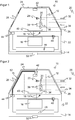
- Fig. 1 1 shows a schematic sectional view through an optoelectronic sensor in an embodiment as a laser scanner 10.
- the laser scanner 10 comprises in rough division a movable scanning unit 12 and a base unit 14.
- the scanning unit 12 is the optical measuring head, while in the base unit 14 further elements such as a supply, Evaluation electronics, connections and the like are housed.
- the scanning unit 12 is set in a rotational movement about an axis of rotation 18 so as to periodically scan a monitoring area 20.
- the laser scanner 10 is housed in a housing 22, which is closed at the top a hood 24 with a rotating around the axis of rotation 18 windscreen 26. Housing 22 and hood 24 could be interpreted differently as shown as part of the base unit 14, since they rest like the base unit 14.
- a light transmitter 28 In the scanning unit 12, a light transmitter 28 generates by means of a transmitting optical system 30 a transmitted light beam 32, which is emitted into the monitoring area 20. If the transmitted light beam 32 hits an object in the surveillance area 20, then a corresponding one returns Light beam as a remitted light 34 back to the laser scanner 10. The remitted light 34 is guided by a receiving optical system 36 to a light receiver 38 and converted there into an electrical received signal. The received signal is transferred to a preprocessing unit 40 where it is amplified, filtered, digitized and the like, for example. The preprocessing unit 40 may also assume other functions such as the control of the light emitter 28 or may not be present in other embodiments.
- the arrangement within the scanning unit 12 is to be understood purely by way of example anyway.
- any other arrangement known per se from single-beam optoelectronic sensors or laser scanners such as a double lens with transmitting optics in the center of a receiving lens or the use of a beam splitter mirror, would be possible.
- the invention is less concerned with the specific embodiment of the scanning unit 12, but rather with an optical data transmission between scanning unit 12 and socket unit 14 to be explained.
- a first optical data transmission unit 42 of the scanning unit 12 exchanges optical signals with a second optical data transmission unit 44 of the socket unit 14 out.
- the control and evaluation functionality can be largely freely distributed between preprocessing unit 40 and evaluation unit 46, but is described as if only the evaluation unit 46 was responsible for it.
- the evaluation unit 46 evaluates the received signal, controls the drive 16 and receives the signal of an angle measuring unit 48, which determines the respective angular position of the scanning unit 12.
- the distance to a touched object is preferably measured with a light transit time method.
- the transmitted light of the light transmitter 28 is modulated in a phase-based system and a phase relationship to the received signal of the light receiver 38 is evaluated.
- short light pulses are emitted at a transmission time as transmission light and the reception time is determined from the reception signal.
- both individual pulse methods each of which determines a distance from a single transmit pulse
- pulse averaging methods are conceivable in which the Received signal is collected after a plurality of successive transmission pulses and statistically evaluated.
- the respective angular position, under which the transmitted light beam 32 was emitted in each case, is also known by the angle measuring unit 48.
- two-dimensional polar coordinates of all object points in a scanning plane are available over the angle and the distance.
- the object positions or object contours are known and can be output via a sensor interface 50.
- the sensor interface 50 or another connection (not shown) serve conversely as a parameterization interface.
- protection fields that may be configured in the surveillance area 20 are monitored for improper interference, and then a fail-safe shutdown signal may be output via the then securely formed interface 50 (e.g., OSSD, Output Signal Switching Device).
- the light emitter 28 can be constructed as a simple light source, for example in the form of a semiconductor diode, but also as a line or matrix arrangement, for example, numerous light sources.
- the light receiver 38 may be a simple receiving surface, such as a photodiode, or an array or line array of light receiving elements, such as a CCD or CMOS chip. This results in not only a single scanning beam, but a corresponding plurality for receiving two-dimensional image data or three-dimensional image data using a light transit time method.
- almost any sensor units in the scanning unit 12 can rotate and thus detect the monitoring area 20, for example, a plurality of sensor units in different angular positions, which complement each other with the same or different physical measurement principles. It is also possible to additionally tilt the scanning unit 12 or to rotate a plurality of superimposed light emitters 28 or light receivers 38 or a particular distance-measuring camera line in order to scan a three-dimensional spatial area.
- optical signal For communication between scanning unit 12 and base unit 14, an optical signal is exchanged via the optical data transmission units 42, 44.
- the more important direction of this communication is mostly from the scanning unit 12 to the base unit 14, since no measurement information can be output without the received signal or information obtained from the received signal.
- bi-directional communication is also often useful, for example to control the light transmitter 28 or to connect to the preprocessing unit 40.
- the possibility of unidirectional communication from the base unit 14 to the scanning unit 12 should not be excluded in principle.
- the optical data transmission units 42, 44 each have a not separately shown light emitter, light receiver or both are provided.
- the optical signal is coupled from the first data transmission unit 42 in the hood 24 and then propagates with total internal reflection within the hood 24 and the windshield 26 as in a light guide. Accordingly, the optical signal at any point of the hood 24 or the front panel 26 can be coupled out of the second data transmission unit 44, in the example of FIG. 1 at the bottom of a support surface, where the hood 24 rests on the rest of the housing 22.
- the optical signal is therefore on the one hand, instead of being emitted freely within the laser scanner 10 and thus to cause stray light, and on the other hand, no additional component is needed, but the hood 24 or windscreen 26 exploited in an additional function.
- the guided through the windscreen 26 optical signal can additionally be used to assess the degree of contamination and thus sufficient transparency for transmitted light beam 32 and remitted light 34. Because pollution also dampens the optical signal, be it due to impaired light pipe properties or due to impurities, at which instead of total internal reflection light can escape and thus be lost. This attenuation can be detected directly from the signal amplitude or indirectly by degrading the data communication, such as increasing a bit error rate.
- time-division multiplexing with time windows for the one and the other data direction or a full-duplex data link for example by wavelength division multiplexing is conceivable.
- another data channel can be created independently of the optical data transmission units 42, 44.
- scattered light can be largely avoided by the light-conducting properties of the windscreen 26, should preferably for the measuring transmitted light beam 32 and the optical signal of the data transmission units 42, 44 a different wavelength are selected, possibly even in addition with corresponding band-limiting optical filters.
- FIG. 2 shows a further embodiment of a laser scanner 10 in a schematic sectional view. Structure, properties and design options largely correspond to the embodiment FIG. 1 and will not be described again.
- the second optical data transmission unit 44 is accommodated at an edge position by way of example.
- the light guide 52 can be made for example of Plexiglas or as a molded part.
- the light guide 52 is integrated into the hood 24, there glued or clipped.
- a thin light guide 52 hardly affects the light paths of the transmitted light beam 32 and the remitted light 34 and settles only in a low attenuation.
- the hood 24 may be constructed in the area outside the windshield 24 and opaque housing material.
Landscapes
- Engineering & Computer Science (AREA)
- Physics & Mathematics (AREA)
- Computer Networks & Wireless Communication (AREA)
- Radar, Positioning & Navigation (AREA)
- Remote Sensing (AREA)
- General Physics & Mathematics (AREA)
- Electromagnetism (AREA)
- Optical Radar Systems And Details Thereof (AREA)
Claims (8)
- Détecteur optoélectronique (10) destiné à détecter des objets dans une zone à surveiller (20), en particulier scanneur à laser, qui comprend un émetteur de lumière (12) pour émettre un rayon lumineux émis (32), un récepteur de lumière (38) pour générer un signal de réception à partir de la lumière (34) réémise par des objets dans une zone à surveiller (20), une unité formant socle (14) pourvue d'une vitre frontale périphérique (26), une unité de balayage (12) mobile par rapport à l'unité formant socle (14) et destinée à balayer périodiquement la zone à surveiller (20), ainsi qu'une unité d'évaluation (46) destinée à saisir des informations sur des objets dans la zone à surveiller (20) à la base du signal de réception,
dans lequel
l'émetteur de lumière (28) et le récepteur de lumière (38) sont agencés dans l'unité de balayage (12) et l'unité de balayage (12) comprend une première unité optique de transmission de données (42) et l'unité formant socle (14) comprend une seconde unité optique de transmission de données (44), afin d'échanger des données via un signal optique en vue de la communication entre l'unité formant socle (12) et l'unité de balayage (14),
caractérisé en ce que
les unités de transmission de données (42, 44) sont réalisées pour l'échange de données via un guide de lumière (26) et en ce que la vitre frontale (26) fait elle-même office de guide de lumière. - Détecteur (10) selon la revendication 1,
dans lequel la vitre frontale (26) forme un capot (24) et le couplage du signal optique a lieu dans un centre du capot (24). - Détecteur (10) selon la revendication 1 ou 2,
dans lequel l'unité d'évaluation (46) est réalisée pour évaluer un degré d'encrassement de la vitre frontale (26) en se basant sur le signal optique. - Détecteur (10) selon la revendication 3,
dans lequel l'évaluation prend en compte un taux d'erreur de la transmission. - Détecteur (10) selon l'une des revendications précédentes,
dans lequel la première unité de transmission de données (42) et la seconde unité de transmission de données (44) sont réalisées pour un multiplexage de longueur d'onde. - Détecteur (10) selon l'une des revendications précédentes,
dans lequel les unités de transmission de données (42, 44) échangent des signaux optiques avec une longueur d'onde autre que celle du rayon lumineux émis (32). - Procédé de détection d'objets dans une zone à surveiller (20), dans lequel un rayon lumineux (32) est émis par un émetteur de lumière (28) dans une unité de balayage (12) susceptible d'être tournée par rapport à une unité formant socle (14), et il est reçu par un récepteur de lumière (38) agencé dans l'unité de balayage (12), et un signal de réception généré de la lumière (34) réémise par des objets dans la zone à surveiller (20) est évalué pour saisir des informations sur des objets dans la zone à surveiller (20), et pour la communication entre l'unité de balayage (12) et l'unité formant socle (14), des données sont échangées via un signal optique entre une première unité optique de transmission de données (42) de l'unité de balayage (12) et une seconde unité optique (44) de transmission de données de l'unité formant socle (14),
caractérisé en ce que
les données sont échangées via un guide de lumière (26) et en ce qu'une vitre frontale (26) fait elle-même office de guide de lumière. - Procédé selon la revendication 7,
dans lequel un degré d'encrassement de la vitre frontale (26) est évalué en se basant sur le signal optique.
Applications Claiming Priority (1)
| Application Number | Priority Date | Filing Date | Title |
|---|---|---|---|
| DE102014107353.3A DE102014107353A1 (de) | 2014-05-26 | 2014-05-26 | Optoelektronischer Sensor und Verfahren zur Erfassung von Objekten |
Publications (2)
| Publication Number | Publication Date |
|---|---|
| EP2950115A1 EP2950115A1 (fr) | 2015-12-02 |
| EP2950115B1 true EP2950115B1 (fr) | 2016-12-28 |
Family
ID=52875584
Family Applications (1)
| Application Number | Title | Priority Date | Filing Date |
|---|---|---|---|
| EP15163302.1A Active EP2950115B1 (fr) | 2014-05-26 | 2015-04-13 | Capteur optoélectronique et procédé de détection d'objets |
Country Status (2)
| Country | Link |
|---|---|
| EP (1) | EP2950115B1 (fr) |
| DE (1) | DE102014107353A1 (fr) |
Cited By (2)
| Publication number | Priority date | Publication date | Assignee | Title |
|---|---|---|---|---|
| DE102018126289A1 (de) * | 2018-10-23 | 2020-04-23 | Valeo Schalter Und Sensoren Gmbh | Verfahren zur Überprüfung der Lichtdurchlässigkeit wenigstens eines Fensters einer optischen Detektionsvorrichtung, optische Detektionsvorrichtung und Lichtdurchlässigkeitsüberprüfungseinrichtung |
| EP4116733A1 (fr) * | 2021-07-09 | 2023-01-11 | Sick Ag | Caméra destinée à la capture des données d'image tridimensionnelle et procédé de vérification de la fonctionnalité d'une caméra |
Families Citing this family (21)
| Publication number | Priority date | Publication date | Assignee | Title |
|---|---|---|---|---|
| US9964437B2 (en) | 2016-05-03 | 2018-05-08 | Datalogic IP Tech, S.r.l. | Laser scanner with reduced internal optical reflection comprising a light detector disposed between an interference filter and a collecting mirror |
| WO2017191665A1 (fr) * | 2016-05-03 | 2017-11-09 | Datalogic IP Tech S.r.I. | Scanner laser |
| US10048120B2 (en) | 2016-05-03 | 2018-08-14 | Datalogic IP Tech, S.r.l. | Laser scanner and optical system |
| US11585905B2 (en) | 2016-05-03 | 2023-02-21 | Datalogic Ip Tech S.R.L. | Laser scanner |
| US10061021B2 (en) | 2016-07-06 | 2018-08-28 | Datalogic IP Tech, S.r.l. | Clutter filter configuration for safety laser scanner |
| DE102016220468B4 (de) | 2016-10-19 | 2025-12-11 | Robert Bosch Gmbh | Lidar-Sensor zur Erfassung eines Objektes |
| DE102016120389B3 (de) * | 2016-10-26 | 2017-09-07 | Sick Ag | Optoelektronischer Sensor und Verfahren zur Erfassung von Objekten in einem Überwachungsbereich |
| EP3415951B1 (fr) * | 2017-06-16 | 2023-06-07 | Leuze electronic GmbH + Co. KG | Capteur optique |
| DE102017125587A1 (de) * | 2017-11-02 | 2019-05-02 | Pepperl + Fuchs Gmbh | Optischer Sensor zum Nachweis von Objekten in einem Erfassungsbereich |
| DE102017223618A1 (de) * | 2017-12-21 | 2019-06-27 | Robert Bosch Gmbh | Optisches Scansystem und Verfahren zur Kalibrierung des optischen Scansystems |
| DE102018202252A1 (de) * | 2018-02-14 | 2019-08-14 | Robert Bosch Gmbh | LiDAR-System, Betriebsverfahren für ein LiDAR-System und Arbeitsvorrichtung |
| DE102018202246A1 (de) * | 2018-02-14 | 2019-08-14 | Robert Bosch Gmbh | LiDAR-System, Betriebsverfahren für ein LiDAR-System und Arbeitsvorrichtung |
| DE102018104787A1 (de) * | 2018-03-02 | 2019-09-05 | Sick Ag | Optoelektronischer Sensor und Herstellungsverfahren für eine Frontscheibe |
| DE102018217482A1 (de) * | 2018-10-12 | 2020-04-16 | Robert Bosch Gmbh | Optisches System mit einem Verschmutzungserkennungssystem, Fahrzeug mit einem optischen System und Verfahren für ein optisches System |
| DE102018217467A1 (de) * | 2018-10-12 | 2020-04-16 | Robert Bosch Gmbh | Optisches System mit einem Verschmutzungserkennungssystem, Fahrzeug mit einem optischen System und Verfahren für ein optisches System |
| DE102018217484A1 (de) * | 2018-10-12 | 2020-04-16 | Robert Bosch Gmbh | Optisches System mit einem Verschmutzungserkennungssystem, Fahrzeug mit einem optischen System und Verfahren für ein optisches System |
| DE102018217488B4 (de) * | 2018-10-12 | 2026-01-15 | Robert Bosch Gmbh | Optisches System umfassend ein Verschmutzungserkennungssystem |
| DE102018217466A1 (de) * | 2018-10-12 | 2020-04-16 | Robert Bosch Gmbh | Optisches System mit einem Verschmutzungserkennungssystem, Fahrzeug mit einem optischen System und Verfahren für ein optisches System |
| DE102022134444A1 (de) * | 2021-12-30 | 2023-07-06 | Motional Ad Llc | System zur charakterisierung von lichtquellen |
| CN115143889A (zh) * | 2022-06-07 | 2022-10-04 | 中国航空工业集团公司沈阳飞机设计研究所 | 一种用于全机静力试验的位移测量装置及方法 |
| WO2026017311A1 (fr) * | 2024-07-17 | 2026-01-22 | Saint-Gobain Sekurit France | Vitre composite ayant une vitre externe, une vitre interne, un guide de lumière et deux films thermoplastiques |
Citations (2)
| Publication number | Priority date | Publication date | Assignee | Title |
|---|---|---|---|---|
| DE102004014041A1 (de) * | 2004-03-19 | 2005-10-13 | Martin Spies | Sensorsystem zur Hinderniserkennung |
| DE102007003023A1 (de) * | 2007-01-20 | 2008-07-31 | Sick Ag | Optoelektronischer Sensor mit Lichtdurchlässigkeitstests der Schutzscheibe durch Totalreflexion |
Family Cites Families (10)
| Publication number | Priority date | Publication date | Assignee | Title |
|---|---|---|---|---|
| DE4340756C5 (de) | 1992-12-08 | 2006-08-10 | Sick Ag | Laserabstandsermittlungsvorrichtung |
| DE19757849C5 (de) | 1997-12-24 | 2013-11-21 | Sick Ag | Scanner und Vorrichtung zur optischen Erfassung von Hindernissen, sowie deren Verwendung |
| DE19927502A1 (de) * | 1999-05-22 | 2000-11-23 | Volkswagen Ag | Abstandsensorik für ein Kraftfahrzeug |
| DE10114362C2 (de) * | 2001-03-22 | 2003-12-24 | Martin Spies | Laserscan-System für Entfernungsmessung |
| JP4228132B2 (ja) * | 2002-10-18 | 2009-02-25 | 株式会社トプコン | 位置測定装置 |
| US7187823B2 (en) | 2004-03-16 | 2007-03-06 | Leica Geosystems Hds Llc | Contact-free slip ring for survey instrumentation |
| DE102004016808A1 (de) * | 2004-04-06 | 2005-10-27 | Robert Bosch Gmbh | Signalisiervorrichtung zur Anzeige von Warn- und/oder Informationshinweisen in Fahrzeugen |
| DE102010022159A1 (de) | 2010-05-20 | 2011-11-24 | Leuze Electronic Gmbh + Co. Kg | Optischer Sensor |
| FR2985300A1 (fr) * | 2012-01-04 | 2013-07-05 | Peugeot Citroen Automobiles Sa | Dispositif de protection assurant au moins une fonction d'eclairage par transfert de lumiere au moyen de renfoncement(s) defini(s) dans une paroi transparente |
| EP2645125B1 (fr) | 2012-03-27 | 2017-05-10 | Sick AG | Laser scanner et procédé destiné à la détection d'objets dans une zone de surveillance |
-
2014
- 2014-05-26 DE DE102014107353.3A patent/DE102014107353A1/de not_active Withdrawn
-
2015
- 2015-04-13 EP EP15163302.1A patent/EP2950115B1/fr active Active
Patent Citations (2)
| Publication number | Priority date | Publication date | Assignee | Title |
|---|---|---|---|---|
| DE102004014041A1 (de) * | 2004-03-19 | 2005-10-13 | Martin Spies | Sensorsystem zur Hinderniserkennung |
| DE102007003023A1 (de) * | 2007-01-20 | 2008-07-31 | Sick Ag | Optoelektronischer Sensor mit Lichtdurchlässigkeitstests der Schutzscheibe durch Totalreflexion |
Cited By (2)
| Publication number | Priority date | Publication date | Assignee | Title |
|---|---|---|---|---|
| DE102018126289A1 (de) * | 2018-10-23 | 2020-04-23 | Valeo Schalter Und Sensoren Gmbh | Verfahren zur Überprüfung der Lichtdurchlässigkeit wenigstens eines Fensters einer optischen Detektionsvorrichtung, optische Detektionsvorrichtung und Lichtdurchlässigkeitsüberprüfungseinrichtung |
| EP4116733A1 (fr) * | 2021-07-09 | 2023-01-11 | Sick Ag | Caméra destinée à la capture des données d'image tridimensionnelle et procédé de vérification de la fonctionnalité d'une caméra |
Also Published As
| Publication number | Publication date |
|---|---|
| EP2950115A1 (fr) | 2015-12-02 |
| DE102014107353A1 (de) | 2015-11-26 |
Similar Documents
| Publication | Publication Date | Title |
|---|---|---|
| EP2950115B1 (fr) | Capteur optoélectronique et procédé de détection d'objets | |
| EP3260885B1 (fr) | Capteur optoélectronique et procédé de détection d'objets | |
| EP2902800B1 (fr) | Capteur optoélectronique et procédé destiné à la détection d'objets dans une zone de surveillance | |
| DE102013107695A1 (de) | Optoelektronischer Sensor und Verfahren zur Erfassung von Objekten | |
| EP2645125B1 (fr) | Laser scanner et procédé destiné à la détection d'objets dans une zone de surveillance | |
| EP2482094B1 (fr) | Capteur optoélectronique mesurant l'éloignement et procédé de détection d'objet | |
| EP3078985B1 (fr) | Capteur optoelectronique et procede de surveillance de transmission d'un disque frontal | |
| DE102014100301B3 (de) | Optoelektronischer Sensor zur Erfassung von Objekten in einem Überwachungsbereich | |
| EP3203263B1 (fr) | Capteur optoélectronique et procédé destiné à la saisie d'objets | |
| EP3699638B1 (fr) | Capteur optoélectronique et procédé de détection d'un objet | |
| EP1947481B1 (fr) | Capteur optoélectronique et procédé de saisie d'objets dans une zone de surveillance | |
| DE102008032216A1 (de) | Vorrichtung zur Erkennung der Anwesenheit eines Objekts im Raum | |
| DE102014105781B4 (de) | Optoelektronischer Sensor und Verfahren zur Erfassung von Messinformationen aus einem Überwachungsbereich | |
| EP4071504B1 (fr) | Capteur optoélectronique et procédé de détection d'objets | |
| EP3330741A1 (fr) | Capteur optoélectronique et procédé de détection d'objets dans une zone de détection | |
| DE102016120389B3 (de) | Optoelektronischer Sensor und Verfahren zur Erfassung von Objekten in einem Überwachungsbereich | |
| EP3208636B1 (fr) | Capteur optoélectronique et procédé destiné à la saisie d'objets | |
| DE202013103233U1 (de) | Optoelektronischer Sensor zur Erfassung von Objekten | |
| EP3699637B1 (fr) | Capteur optoélectronique et procédé de détection d'un objet | |
| EP4067939B1 (fr) | Capteur optoélectronique | |
| DE202014102451U1 (de) | Optoelektronischer Sensor zur Erfassung von Objekten | |
| EP4071503B1 (fr) | Capteur optoélectronique et procédé de détection des objets | |
| DE202014101940U1 (de) | Optoelektronischer Sensor zur Erfassung von Messinformationen aus einem Überwachungsbereich | |
| DE102017103791B4 (de) | Optoelektronischer Sensor und Verfahren zur Erfassung von Objekten | |
| EP3951427A1 (fr) | Capteur optoélectronique et procédé de surveillance de par-brise |
Legal Events
| Date | Code | Title | Description |
|---|---|---|---|
| AK | Designated contracting states |
Kind code of ref document: A1 Designated state(s): AL AT BE BG CH CY CZ DE DK EE ES FI FR GB GR HR HU IE IS IT LI LT LU LV MC MK MT NL NO PL PT RO RS SE SI SK SM TR |
|
| AX | Request for extension of the european patent |
Extension state: BA ME |
|
| PUAI | Public reference made under article 153(3) epc to a published international application that has entered the european phase |
Free format text: ORIGINAL CODE: 0009012 |
|
| 17P | Request for examination filed |
Effective date: 20151030 |
|
| RBV | Designated contracting states (corrected) |
Designated state(s): AL AT BE BG CH CY CZ DE DK EE ES FI FR GB GR HR HU IE IS IT LI LT LU LV MC MK MT NL NO PL PT RO RS SE SI SK SM TR |
|
| 17Q | First examination report despatched |
Effective date: 20160118 |
|
| GRAP | Despatch of communication of intention to grant a patent |
Free format text: ORIGINAL CODE: EPIDOSNIGR1 |
|
| RIC1 | Information provided on ipc code assigned before grant |
Ipc: G01S 7/481 20060101AFI20160805BHEP Ipc: G01S 7/00 20060101ALI20160805BHEP Ipc: G01S 7/497 20060101ALN20160805BHEP Ipc: G01S 17/42 20060101ALI20160805BHEP Ipc: F21V 8/00 20060101ALI20160805BHEP |
|
| INTG | Intention to grant announced |
Effective date: 20160909 |
|
| GRAS | Grant fee paid |
Free format text: ORIGINAL CODE: EPIDOSNIGR3 |
|
| GRAA | (expected) grant |
Free format text: ORIGINAL CODE: 0009210 |
|
| AK | Designated contracting states |
Kind code of ref document: B1 Designated state(s): AL AT BE BG CH CY CZ DE DK EE ES FI FR GB GR HR HU IE IS IT LI LT LU LV MC MK MT NL NO PL PT RO RS SE SI SK SM TR |
|
| REG | Reference to a national code |
Ref country code: GB Ref legal event code: FG4D Free format text: NOT ENGLISH |
|
| REG | Reference to a national code |
Ref country code: CH Ref legal event code: EP |
|
| REG | Reference to a national code |
Ref country code: AT Ref legal event code: REF Ref document number: 857769 Country of ref document: AT Kind code of ref document: T Effective date: 20170115 |
|
| REG | Reference to a national code |
Ref country code: IE Ref legal event code: FG4D Free format text: LANGUAGE OF EP DOCUMENT: GERMAN |
|
| REG | Reference to a national code |
Ref country code: DE Ref legal event code: R096 Ref document number: 502015000426 Country of ref document: DE |
|
| PG25 | Lapsed in a contracting state [announced via postgrant information from national office to epo] |
Ref country code: LV Free format text: LAPSE BECAUSE OF FAILURE TO SUBMIT A TRANSLATION OF THE DESCRIPTION OR TO PAY THE FEE WITHIN THE PRESCRIBED TIME-LIMIT Effective date: 20161228 |
|
| REG | Reference to a national code |
Ref country code: FR Ref legal event code: PLFP Year of fee payment: 3 |
|
| REG | Reference to a national code |
Ref country code: LT Ref legal event code: MG4D |
|
| PG25 | Lapsed in a contracting state [announced via postgrant information from national office to epo] |
Ref country code: NO Free format text: LAPSE BECAUSE OF FAILURE TO SUBMIT A TRANSLATION OF THE DESCRIPTION OR TO PAY THE FEE WITHIN THE PRESCRIBED TIME-LIMIT Effective date: 20170328 Ref country code: GR Free format text: LAPSE BECAUSE OF FAILURE TO SUBMIT A TRANSLATION OF THE DESCRIPTION OR TO PAY THE FEE WITHIN THE PRESCRIBED TIME-LIMIT Effective date: 20170329 Ref country code: SE Free format text: LAPSE BECAUSE OF FAILURE TO SUBMIT A TRANSLATION OF THE DESCRIPTION OR TO PAY THE FEE WITHIN THE PRESCRIBED TIME-LIMIT Effective date: 20161228 Ref country code: LT Free format text: LAPSE BECAUSE OF FAILURE TO SUBMIT A TRANSLATION OF THE DESCRIPTION OR TO PAY THE FEE WITHIN THE PRESCRIBED TIME-LIMIT Effective date: 20161228 |
|
| REG | Reference to a national code |
Ref country code: NL Ref legal event code: MP Effective date: 20161228 |
|
| PG25 | Lapsed in a contracting state [announced via postgrant information from national office to epo] |
Ref country code: HR Free format text: LAPSE BECAUSE OF FAILURE TO SUBMIT A TRANSLATION OF THE DESCRIPTION OR TO PAY THE FEE WITHIN THE PRESCRIBED TIME-LIMIT Effective date: 20161228 Ref country code: RS Free format text: LAPSE BECAUSE OF FAILURE TO SUBMIT A TRANSLATION OF THE DESCRIPTION OR TO PAY THE FEE WITHIN THE PRESCRIBED TIME-LIMIT Effective date: 20161228 Ref country code: FI Free format text: LAPSE BECAUSE OF FAILURE TO SUBMIT A TRANSLATION OF THE DESCRIPTION OR TO PAY THE FEE WITHIN THE PRESCRIBED TIME-LIMIT Effective date: 20161228 |
|
| PG25 | Lapsed in a contracting state [announced via postgrant information from national office to epo] |
Ref country code: NL Free format text: LAPSE BECAUSE OF FAILURE TO SUBMIT A TRANSLATION OF THE DESCRIPTION OR TO PAY THE FEE WITHIN THE PRESCRIBED TIME-LIMIT Effective date: 20161228 |
|
| PG25 | Lapsed in a contracting state [announced via postgrant information from national office to epo] |
Ref country code: IS Free format text: LAPSE BECAUSE OF FAILURE TO SUBMIT A TRANSLATION OF THE DESCRIPTION OR TO PAY THE FEE WITHIN THE PRESCRIBED TIME-LIMIT Effective date: 20170428 Ref country code: EE Free format text: LAPSE BECAUSE OF FAILURE TO SUBMIT A TRANSLATION OF THE DESCRIPTION OR TO PAY THE FEE WITHIN THE PRESCRIBED TIME-LIMIT Effective date: 20161228 Ref country code: RO Free format text: LAPSE BECAUSE OF FAILURE TO SUBMIT A TRANSLATION OF THE DESCRIPTION OR TO PAY THE FEE WITHIN THE PRESCRIBED TIME-LIMIT Effective date: 20161228 Ref country code: CZ Free format text: LAPSE BECAUSE OF FAILURE TO SUBMIT A TRANSLATION OF THE DESCRIPTION OR TO PAY THE FEE WITHIN THE PRESCRIBED TIME-LIMIT Effective date: 20161228 Ref country code: SK Free format text: LAPSE BECAUSE OF FAILURE TO SUBMIT A TRANSLATION OF THE DESCRIPTION OR TO PAY THE FEE WITHIN THE PRESCRIBED TIME-LIMIT Effective date: 20161228 |
|
| PG25 | Lapsed in a contracting state [announced via postgrant information from national office to epo] |
Ref country code: IT Free format text: LAPSE BECAUSE OF FAILURE TO SUBMIT A TRANSLATION OF THE DESCRIPTION OR TO PAY THE FEE WITHIN THE PRESCRIBED TIME-LIMIT Effective date: 20161228 Ref country code: BG Free format text: LAPSE BECAUSE OF FAILURE TO SUBMIT A TRANSLATION OF THE DESCRIPTION OR TO PAY THE FEE WITHIN THE PRESCRIBED TIME-LIMIT Effective date: 20170328 Ref country code: PT Free format text: LAPSE BECAUSE OF FAILURE TO SUBMIT A TRANSLATION OF THE DESCRIPTION OR TO PAY THE FEE WITHIN THE PRESCRIBED TIME-LIMIT Effective date: 20170428 Ref country code: SM Free format text: LAPSE BECAUSE OF FAILURE TO SUBMIT A TRANSLATION OF THE DESCRIPTION OR TO PAY THE FEE WITHIN THE PRESCRIBED TIME-LIMIT Effective date: 20161228 Ref country code: PL Free format text: LAPSE BECAUSE OF FAILURE TO SUBMIT A TRANSLATION OF THE DESCRIPTION OR TO PAY THE FEE WITHIN THE PRESCRIBED TIME-LIMIT Effective date: 20161228 Ref country code: ES Free format text: LAPSE BECAUSE OF FAILURE TO SUBMIT A TRANSLATION OF THE DESCRIPTION OR TO PAY THE FEE WITHIN THE PRESCRIBED TIME-LIMIT Effective date: 20161228 |
|
| REG | Reference to a national code |
Ref country code: DE Ref legal event code: R097 Ref document number: 502015000426 Country of ref document: DE |
|
| PLBE | No opposition filed within time limit |
Free format text: ORIGINAL CODE: 0009261 |
|
| STAA | Information on the status of an ep patent application or granted ep patent |
Free format text: STATUS: NO OPPOSITION FILED WITHIN TIME LIMIT |
|
| PG25 | Lapsed in a contracting state [announced via postgrant information from national office to epo] |
Ref country code: DK Free format text: LAPSE BECAUSE OF FAILURE TO SUBMIT A TRANSLATION OF THE DESCRIPTION OR TO PAY THE FEE WITHIN THE PRESCRIBED TIME-LIMIT Effective date: 20161228 |
|
| 26N | No opposition filed |
Effective date: 20170929 |
|
| REG | Reference to a national code |
Ref country code: IE Ref legal event code: MM4A |
|
| PG25 | Lapsed in a contracting state [announced via postgrant information from national office to epo] |
Ref country code: MC Free format text: LAPSE BECAUSE OF FAILURE TO SUBMIT A TRANSLATION OF THE DESCRIPTION OR TO PAY THE FEE WITHIN THE PRESCRIBED TIME-LIMIT Effective date: 20161228 |
|
| PG25 | Lapsed in a contracting state [announced via postgrant information from national office to epo] |
Ref country code: SI Free format text: LAPSE BECAUSE OF FAILURE TO SUBMIT A TRANSLATION OF THE DESCRIPTION OR TO PAY THE FEE WITHIN THE PRESCRIBED TIME-LIMIT Effective date: 20161228 Ref country code: LU Free format text: LAPSE BECAUSE OF NON-PAYMENT OF DUE FEES Effective date: 20170413 |
|
| REG | Reference to a national code |
Ref country code: BE Ref legal event code: MM Effective date: 20170430 |
|
| REG | Reference to a national code |
Ref country code: FR Ref legal event code: PLFP Year of fee payment: 4 |
|
| PG25 | Lapsed in a contracting state [announced via postgrant information from national office to epo] |
Ref country code: IE Free format text: LAPSE BECAUSE OF NON-PAYMENT OF DUE FEES Effective date: 20170413 |
|
| PG25 | Lapsed in a contracting state [announced via postgrant information from national office to epo] |
Ref country code: BE Free format text: LAPSE BECAUSE OF NON-PAYMENT OF DUE FEES Effective date: 20170430 |
|
| PG25 | Lapsed in a contracting state [announced via postgrant information from national office to epo] |
Ref country code: MT Free format text: LAPSE BECAUSE OF FAILURE TO SUBMIT A TRANSLATION OF THE DESCRIPTION OR TO PAY THE FEE WITHIN THE PRESCRIBED TIME-LIMIT Effective date: 20161228 |
|
| PG25 | Lapsed in a contracting state [announced via postgrant information from national office to epo] |
Ref country code: HU Free format text: LAPSE BECAUSE OF FAILURE TO SUBMIT A TRANSLATION OF THE DESCRIPTION OR TO PAY THE FEE WITHIN THE PRESCRIBED TIME-LIMIT; INVALID AB INITIO Effective date: 20150413 |
|
| PG25 | Lapsed in a contracting state [announced via postgrant information from national office to epo] |
Ref country code: CY Free format text: LAPSE BECAUSE OF FAILURE TO SUBMIT A TRANSLATION OF THE DESCRIPTION OR TO PAY THE FEE WITHIN THE PRESCRIBED TIME-LIMIT Effective date: 20161228 |
|
| PG25 | Lapsed in a contracting state [announced via postgrant information from national office to epo] |
Ref country code: MK Free format text: LAPSE BECAUSE OF FAILURE TO SUBMIT A TRANSLATION OF THE DESCRIPTION OR TO PAY THE FEE WITHIN THE PRESCRIBED TIME-LIMIT Effective date: 20161228 |
|
| GBPC | Gb: european patent ceased through non-payment of renewal fee |
Effective date: 20190413 |
|
| PG25 | Lapsed in a contracting state [announced via postgrant information from national office to epo] |
Ref country code: GB Free format text: LAPSE BECAUSE OF NON-PAYMENT OF DUE FEES Effective date: 20190413 |
|
| PG25 | Lapsed in a contracting state [announced via postgrant information from national office to epo] |
Ref country code: TR Free format text: LAPSE BECAUSE OF FAILURE TO SUBMIT A TRANSLATION OF THE DESCRIPTION OR TO PAY THE FEE WITHIN THE PRESCRIBED TIME-LIMIT Effective date: 20161228 |
|
| PG25 | Lapsed in a contracting state [announced via postgrant information from national office to epo] |
Ref country code: AL Free format text: LAPSE BECAUSE OF FAILURE TO SUBMIT A TRANSLATION OF THE DESCRIPTION OR TO PAY THE FEE WITHIN THE PRESCRIBED TIME-LIMIT Effective date: 20161228 |
|
| PGFP | Annual fee paid to national office [announced via postgrant information from national office to epo] |
Ref country code: AT Payment date: 20230414 Year of fee payment: 9 |
|
| PGFP | Annual fee paid to national office [announced via postgrant information from national office to epo] |
Ref country code: CH Payment date: 20240501 Year of fee payment: 10 |
|
| PGFP | Annual fee paid to national office [announced via postgrant information from national office to epo] |
Ref country code: FR Payment date: 20240422 Year of fee payment: 10 |
|
| REG | Reference to a national code |
Ref country code: AT Ref legal event code: MM01 Ref document number: 857769 Country of ref document: AT Kind code of ref document: T Effective date: 20240413 |
|
| PG25 | Lapsed in a contracting state [announced via postgrant information from national office to epo] |
Ref country code: AT Free format text: LAPSE BECAUSE OF NON-PAYMENT OF DUE FEES Effective date: 20240413 |
|
| PG25 | Lapsed in a contracting state [announced via postgrant information from national office to epo] |
Ref country code: AT Free format text: LAPSE BECAUSE OF NON-PAYMENT OF DUE FEES Effective date: 20240413 |
|
| PGFP | Annual fee paid to national office [announced via postgrant information from national office to epo] |
Ref country code: DE Payment date: 20250417 Year of fee payment: 11 |
|
| REG | Reference to a national code |
Ref country code: CH Ref legal event code: H13 Free format text: ST27 STATUS EVENT CODE: U-0-0-H10-H13 (AS PROVIDED BY THE NATIONAL OFFICE) Effective date: 20251125 |
|
| PG25 | Lapsed in a contracting state [announced via postgrant information from national office to epo] |
Ref country code: FR Free format text: LAPSE BECAUSE OF NON-PAYMENT OF DUE FEES Effective date: 20250430 |
|
| PG25 | Lapsed in a contracting state [announced via postgrant information from national office to epo] |
Ref country code: CH Free format text: LAPSE BECAUSE OF NON-PAYMENT OF DUE FEES Effective date: 20250430 |