EP2950123A1 - Rotateur de polarisation - Google Patents
Rotateur de polarisation Download PDFInfo
- Publication number
- EP2950123A1 EP2950123A1 EP15168594.8A EP15168594A EP2950123A1 EP 2950123 A1 EP2950123 A1 EP 2950123A1 EP 15168594 A EP15168594 A EP 15168594A EP 2950123 A1 EP2950123 A1 EP 2950123A1
- Authority
- EP
- European Patent Office
- Prior art keywords
- polarization
- polarizer
- layers
- polarization rotator
- radiation
- Prior art date
- Legal status (The legal status is an assumption and is not a legal conclusion. Google has not performed a legal analysis and makes no representation as to the accuracy of the status listed.)
- Withdrawn
Links
Images


Classifications
-
- G—PHYSICS
- G02—OPTICS
- G02B—OPTICAL ELEMENTS, SYSTEMS OR APPARATUS
- G02B5/00—Optical elements other than lenses
- G02B5/30—Polarising elements
- G02B5/3025—Polarisers, i.e. arrangements capable of producing a definite output polarisation state from an unpolarised input state
- G02B5/3058—Polarisers, i.e. arrangements capable of producing a definite output polarisation state from an unpolarised input state comprising electrically conductive elements, e.g. wire grids, conductive particles
-
- G—PHYSICS
- G02—OPTICS
- G02B—OPTICAL ELEMENTS, SYSTEMS OR APPARATUS
- G02B27/00—Optical systems or apparatus not provided for by any of the groups G02B1/00 - G02B26/00, G02B30/00
- G02B27/28—Optical systems or apparatus not provided for by any of the groups G02B1/00 - G02B26/00, G02B30/00 for polarising
- G02B27/286—Optical systems or apparatus not provided for by any of the groups G02B1/00 - G02B26/00, G02B30/00 for polarising for controlling or changing the state of polarisation, e.g. transforming one polarisation state into another
-
- G—PHYSICS
- G06—COMPUTING OR CALCULATING; COUNTING
- G06F—ELECTRIC DIGITAL DATA PROCESSING
- G06F17/00—Digital computing or data processing equipment or methods, specially adapted for specific functions
- G06F17/10—Complex mathematical operations
-
- G—PHYSICS
- G06—COMPUTING OR CALCULATING; COUNTING
- G06F—ELECTRIC DIGITAL DATA PROCESSING
- G06F30/00—Computer-aided design [CAD]
- G06F30/20—Design optimisation, verification or simulation
-
- H—ELECTRICITY
- H01—ELECTRIC ELEMENTS
- H01Q—ANTENNAS, i.e. RADIO AERIALS
- H01Q15/00—Devices for reflection, refraction, diffraction or polarisation of waves radiated from an antenna, e.g. quasi-optical devices
- H01Q15/0006—Devices acting selectively as reflecting surface, as diffracting or as refracting device, e.g. frequency filtering or angular spatial filtering devices
- H01Q15/0013—Devices acting selectively as reflecting surface, as diffracting or as refracting device, e.g. frequency filtering or angular spatial filtering devices said selective devices working as frequency-selective reflecting surfaces, e.g. FSS, dichroic plates, surfaces being partly transmissive and reflective
- H01Q15/0026—Devices acting selectively as reflecting surface, as diffracting or as refracting device, e.g. frequency filtering or angular spatial filtering devices said selective devices working as frequency-selective reflecting surfaces, e.g. FSS, dichroic plates, surfaces being partly transmissive and reflective said selective devices having a stacked geometry or having multiple layers
-
- H—ELECTRICITY
- H01—ELECTRIC ELEMENTS
- H01Q—ANTENNAS, i.e. RADIO AERIALS
- H01Q15/00—Devices for reflection, refraction, diffraction or polarisation of waves radiated from an antenna, e.g. quasi-optical devices
- H01Q15/24—Polarising devices; Polarisation filters
- H01Q15/242—Polarisation converters
- H01Q15/246—Polarisation converters rotating the plane of polarisation of a linear polarised wave
-
- G—PHYSICS
- G02—OPTICS
- G02B—OPTICAL ELEMENTS, SYSTEMS OR APPARATUS
- G02B27/00—Optical systems or apparatus not provided for by any of the groups G02B1/00 - G02B26/00, G02B30/00
- G02B27/0012—Optical design, e.g. procedures, algorithms, optimisation routines
Definitions
- the present invention is in the field of polarization filters and more particularly relates to polarization rotation modules for use in arrays of electro-magnetic radiation receiving or transmitting elements.
- Antenna arrays and in general, arrays of modules for receiving and/or transmitting electro-magnetic radiation (hereinafter transceiver modules), are widely used for various applications. Such arrays may provide high reception/or transmission gains as well as the ability to control the directions of the transmission or reception beams.
- the transceiver modules of an antenna array are, in many cases, arranged in a lattice defining tiling of reception and transmission modules that are typically similar to one another.
- polarization filters such as a polarizer or polarization rotator, are arranged in front of the antenna array.
- the polarization filter is configured to extend laterally over several or all of the transceiver modules so as to cover the fields of view of several of them.
- Such a polarization filter may be configured for example utilizing several wire-grid layers each including an arrangement of parallel conductive lines (e.g. wires and/or printed conductive lines).
- the conductive lines are arranged parallel to one another along a direction defining polarization extinction axis of the corresponding layer of the polarization filter.
- radiation components which are polarized parallel to the extinction axis of the layer, are reflected back or suppressed when interacting with the layer, and are therefore substantially prevented from being transmitted through the layer.
- wire-grid polarization filters are described for example in U.S. patent No. 6,788,461 and U.S. patent application publication No. 2006/0119937 . Acknowledgement of these references herein is not to be inferred as meaning that these are in any way relevant to the patentability of the presently disclosed subject matter.
- transceiver modules such as antenna elements
- the transceiver elements operate under similar intrinsic system conditions, and function in a similar way. For example, in some cases it may be desired that all the elements function in the same way, or that the elements are grouped into one or more groups of elements operating under similar intrinsic conditions.
- the present invention provides a polarization filter for placement in front of an array of transceiver elements/antennas.
- the polarization filter is configured in accordance with the arrangement of the elements/antennas in the array so as to have a substantially similar effect on all of the elements, or to have a substantially similar effect on a certain group(s) of elements in the array.
- the polarization filter configuration of the present invention reduces or eliminates any difference between the intrinsic conditions to which different elements of the array are exposed.
- the present invention provides a polarization filter system, and a method for applying polarization filtration to radiation propagating to, or from, an array of transceiver elements, while having a substantially similar effect on all of the transceiver elements, thereby reducing any differentiation between the intrinsic conditions to which the different transceiver elements are exposed.
- transceiver elements/modules is used herein to designate modules/elements that are capable of transmitting and/or receiving electro-magnetic (EM) radiation.
- antenna elements/modules are considered, arranged to form an antenna array.
- antenna elements and/or antenna modules are used interchangeably to designate transceiver elements in general, and the phrase antenna array is used to designate an array of receiving and/or transmitting modules.
- antenna-module/element and antenna-array are used herein to designate in general any kind of modules capable of transmitting and/or receiving electro-magnetic radiation such as light source modules (e.g. lasers or light emitting diodes (LEDS)), optical detectors or emitters and others.
- light source modules e.g. lasers or light emitting diodes (LEDS)
- LEDS light emitting diodes
- the term internal / intrinsic conditions is used herein to designate conditions that affect operation of the transceiver modules (of the antenna elements) and which are related to configuration of the system in which the antenna elements reside. This is as opposed to extrinsic conditions relating to the nature of the radiation propagating to/from the antenna elements and/or to the surroundings, external to the system, through which the radiation propagates.
- a transmitting and/or receiving array including an array TR of antenna elements E i,j and a polarization filter PR is illustrated in Fig. 1 .
- the conventional polarization filters PR used with such arrays are, in many cases, a source variable intrinsic conditions, which have different effect on different antenna elements E i,j of the array TR.
- a polarization filter configured for rotating the polarization of the radiation passing therethrough by a certain polarization rotation angle ⁇ (e.g. 45°) may include a stack of wire-grid polarizers (here four polarizers L1 to L4) arranged with different relative orientations so as to apply polarization rotation to radiation passing through the stack.
- the polarizers are implemented by patterned elements, such as conductive wire grid structures, with a certain spatial periodicity of the pattern. Accordingly, as the different polarizers are stacked with different relative orientations with respect to one another, the entire polarization filter PR of the conventional technique may have no spatial periodicity, (or it may be periodic only at very large length scales (e.g. in the order of, or larger than the entire antenna array). For example, orientation angles ⁇ 1 to ⁇ K of the polarizers in such filters are in many cases selected so as to equally divide the polarization rotation angle ⁇ (e.g.
- conventional polarization filters PR including more than two polarizers (i.e. for which K>2), may have no spatial periodicity of relatively long length scale (larger than the periodicity of the antenna elements' array) which is meant to be placed behind of the polarization rotation filter PR. This may result in each of the transceiver/antenna elements E i,j "seeing" a different configuration/pattern of the polarization filter PR in its field of view.
- the polarization rotation filter PR may have a different effect on different antenna elements E i,j , which either deteriorates the performance of such system as a whole, or is required to be taken into account during the design stage of such a system.
- specific computations and/or simulations are typically required for each of the antenna elements (e.g. during the system design/calibration stage(s)) to estimate their operation, while including the different intrinsic effects that such a polarization rotation filter has on the different elements.
- this may be highly computationally intensive, and may result in less than optimal operation of the antenna system, and, additionally, might require extensive time and computational resources at the stages of system design and/or at later stages (e.g. at a system calibration stage).
- the polarizer is configured in accordance with the arrangement of the array of transmitting/receiving elements that is to be located behind it, such that one or more pluralities/groups of transmitting/receiving elements are exposed to substantially similar patterns of the polarization rotator in their fields of view. This simplifies the design of the system and/or its calibration, since each group of transmitting/receiving elements, together with their respective part of the polarizer, being in their field of view, are similar to one another in configuration and in operation.
- a polarization rotator (polarization rotation filter) including a plurality of polarizer layers stacked along a general direction of radiation propagation therethrough.
- Each of the polarizer layers implements a respective wired grid pattern which defines a respective extinction axis, such that extinct components of the radiation are polarized along that respective extinction axis when radiation interacts with the respective polarizer layer.
- each pair of consecutive polarizer layers of the polarization rotator are arranged such that their respective extinction axes have different orientations, thereby affecting polarization rotation of the radiation interacting with the polarization rotator.
- the wire-grid patterns of the polarizer layers are configured as continuous patterns defining relative orientations of the extinction axes such as to define, in the polarization rotator, a tiling of a plurality of substantially identical polarization rotation unit cells, which are arranged with predetermined respective spatial periods A and B along two lateral axes spanning the tiling.
- a radiation module e.g. antenna module
- an array of elements i.e. receiving, transmitting, or transceiving elements; e.g. antenna elements
- a polarization rotator which is configured according to the present invention and defines a tiling of a plurality of substantially identical polarization rotation unit cells.
- the elements are arranged in a plane substantially parallel to the tiling of the plurality of the polarization rotation unit cells.
- the elements are arranged with respective spatial periodicities A' and B' along each of the two lateral axes spanning the tiling, where the respective spatial periodicities A' and B' are, respectively, integer multiples of the predetermined spatial periods A and B of the polarization rotation unit cells. Accordingly, the antenna elements are exposed to substantially similar wire-grid patterns of the polarization rotator's layers in their respective fields of view.
- the lateral extent of the polarization rotator is configured to be greater than a lateral extent of the arrangement of elements/antennas along the two lateral axes spanning the tiling such that the field of view of each of the elements is entirely covered by the polarization rotator.
- each of the elements/antenna-elements is associated with one or more of the polarization rotator unit cells covering its field of view.
- the polarization rotator includes a number of N polarization rotation layers.
- the layers are arranged in a stack and configured for rotating the polarization of the radiation by a predetermined angle ⁇ .
- the number of polarization rotation layers N is selected in accordance with a desired width ⁇ of the operational wavelength band of the polarization rotator such that for wider bands a greater number of layers N is used.
- the polarizer layers of the polarization rotator include continuous wire-grid patterns which are formed with corresponding respective pitches d k selected such that the continuous wire-grid patterns are periodic along a certain lateral axis with spatial periodicity N*d, where N is an integer number and d is a predetermined value associated with a nominal pitch distance.
- N is an integer number
- d is a predetermined value associated with a nominal pitch distance.
- the continuous wire-grid pattern of each polarizer layer is formed as an arrangement of a plurality of continuous conductive line regions spaced apart from one another and oriented along the extinction axis of the polarizer layer.
- the continuous conductive line regions of the wire-grid pattern may be spaced from one another at a distance of less than a nominal wavelength ⁇ of the radiation which is to be polarized.
- at least some of said polarizer layers include a dielectric substrate with the plurality of continuous conductive line regions printed thereon.
- one or more spacer layers may be arranged in between at least two of the polarizer layers.
- the dielectric substrate may include at least one of a ceramic and glass-reinforced epoxy laminate material, and the spacer layer may include structural foam.
- the conductive line regions of at least one polarizer layer may be formed utilizing conductive wires arranged in the layer.
- an antenna including an array of antenna elements and a polarization rotator.
- the antenna elements of the array are arranged with spatial periodicities, A' and B', with respect to two lateral axes of the antenna.
- the polarization rotator includes a stack of a plurality of K polarizer layers which are stacked along a general direction of radiation propagation to or from the antenna elements.
- the plurality of K polarizer layers respectively implement continuous wired grid patterns oriented so as to rotate the polarization of the radiation.
- the antenna is configured/implemented utilizing as an integrated structure which includes at a stack printed circuit boards.
- the stack of printed circuit boards includes least one printed circuit layer with the antenna array printed thereon, and one or more printed circuit board with one or more of the polarizer layers printed thereon.
- the array of antenna elements may be implemented as a one dimensional array.
- the array of antenna elements may be implemented as a two dimensional array of antenna elements.
- the antenna elements may be arranged in a rectangular lattice with spatial periodicities A' and B' along the two respective axes spanning the lattice. This feature may be used to provide that the antenna elements are exposed to substantially similar wire-grid patterns of the polarization rotator's layers in their respective fields of view.
- the antenna elements may be arranged in a Triangular or an Hexagonal lattice with spatial periodicities A' and B' along two axes spanning the lattice respectively.
- the antenna elements may thereby be associated with two or more groups of antenna elements, wherein the antenna elements of each group are exposed to substantially similar wire-grid patterns of the polarization rotator's layers in their fields of view.
- d is a predetermined value
- N k is an integer or a rational number associated with each polarizer layer k respectively
- ⁇ k is the orientation of the respective polarizer layer k.
- k is the index of said polarizer layer in the stack of K polarizer layers.
- d is a predetermined value
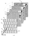
- Fig. 2A schematically illustrating the configuration of a polarization rotator module 100 (e.g. filter) according to an embodiment of the present invention.
- the polarization rotator 100 includes a plurality of K polarizer layers PL 1 to PL K stacked one on top of the other (e.g. stacked along a general direction Z of radiation propagation through the polarization rotator module 100).
- a capital K is used to denote the total number of polarizer layers in the polarization rotator module 100, and k indicates the order index of each layer in the stack (1 ⁇ k ⁇ K).
- Each layer PL k of the polarizer layers PL 1 to PL K is configured as a polarization filter associated with a certain respective extinction axis EX k and is adapted to filter (e.g. extinct / reflect back) radiation components which are polarized along the extinction axis EX k when interacting with /incident on the layer PL k .
- the polarizer layers PL k implement respective patterns PT k defining the directions/orientations ⁇ k of their respective extinction axes EX k .
- the layers PL 1 to PL K e.g. their respective patterns PT k and the orientations ⁇ k thereof, are configured to affect polarization rotation to radiation successively interacting therewith.
- respective extinction axes EX k of different polarizer layers PL k are differently oriented, so as to rotate the polarization of radiation interacting with the polarization rotator module 100.
- the patterns PT k implemented by the respective polarizer layers PL k are configured as continuous patterns.
- the patterns PT k of the polarizer layers PL k are arranged such that the extinction axes EX 1 - EX K of the layers are oriented with orientation angles ⁇ 1 to ⁇ K , that are specifically selected such that a plurality of substantially identical polarization rotation unit cells UC n,m are defined by the polarization rotator module 100. More particularly, as illustrated in the Fig.
- the polarization rotator module 100 of this example can be sectioned into 25 polarization rotation unit cells UC 1,1 to UC 5,15 having similar configurations and arranged in a two dimensional tiling (e.g. defining a lattice of unit cells UC n,m of similar configurations and electrical/optical properties).
- a two dimensional arrangement/tiling of such polarization rotation unit cells is described, a person of ordinary skill in the art will readily appreciate that the same technique can also be used to configure the polarization rotation module 100 to define a one dimensional tiling of similar unit cells.
- the configuration of the polarization rotator module 100 of the invention allows to place the polarization rotator module 100 in front of an array (1D or 2D array) of radiation transmitting and/or receiving elements (e.g. antenna elements) such that the transceiving elements are exposed to substantially similar patterns of the polarization rotator's layers in their respective fields of view. Accordingly, the polarization rotator module has the same effect on all the transceiving elements. This may obviate a need to separately design and/or calibrate the reception/transmission operation of each of the transceiving elements in accordance with the particular configuration (e.g. layer patterns) of the section of the polarization rotation module which is located in front of it in its field of view.
- the particular configuration e.g. layer patterns
- angles ⁇ 1 to ⁇ K of the respective patterns PT k of the polarizer layers PL k are specifically selected in accordance with the desired dimensions/special periodicities A and B of the desired unit cells UC n,m to be defined in the polarization rotator 100.
- a and B designate the dimensions/periodicities of the unit cells along the two lateral axes X and Y of the polarization rotator 100 respectively.
- ⁇ 1 0°, which is the orientation angle of the pattern PT 1 (or of the extinction axis EX 1 thereof) of the first layer PL 1 is used here as a reference, relative to which the angles ⁇ k of the patterns of all of the other polarization layers PL k are measured.
- the terms spatial periodicities and dimensions (i.e. A and B) of the unit cells UC n,m are used here interchangeably.
- the angles ⁇ k are in fact determined based on the desired spatial periodicities A and B of the unit cells tiling along the lateral directions X and Y respectively.
- a and B also designate the lateral dimensions thereof.
- the patterns PT k of the polarization layers PL k may be implemented as wire grid patterns, each formed as an arrangement CL k of a plurality of substantially parallel and continuous conductive line regions, which are spaced apart from one another and oriented along the respective extinction axis EX k of its corresponding polarizer layer PL k . Accordingly, radiation components polarized along the conductive lines CL k induce electric current in the conductive lines and are thus substantially reflected/ absorbed thereby when interacting with the polarizer layer PL k , while other polarization components (e.g. polarized perpendicularly to the conductive lines) are substantially not absorbed/reflected but mostly substantially pass the polarizer layer PL k un-affected.
- polarization components e.g. polarized perpendicularly to the conductive lines
- the d k pitch distance of conductive lines CL k of the respective wire grid patterns PT k is typically selected to be smaller than the nominal wavelength ⁇ n of the wavelength band of the radiation that is to be affected (its polarization rotated) by the polarization rotator module 100.
- the conductive lines CL k of the wire grid patterns PT k are typically spaced apart from one another with distances d k substantially smaller than the nominal wavelength ⁇ n (d k ⁇ ⁇ n ) in order to provide efficient extinction (e.g. reflection) of radiation components polarized along the conductive lines CL k .
- the number K of polarization rotation layers PL k may be selected in accordance with the width ⁇ of the wavelength band of the radiation considered and total angle ⁇ by which the polarization of the radiation is to be rotated by the polarization rotator 100. For example, for larger polarization rotation angles ⁇ and/or for broader band widths ⁇ , a greater number K of polarizer layers PL k may generally be used. Thus, proper selection of the number K of polarizer layers provides that polarization of radiation with wavelengths ⁇ being in the bandwidth X n - ⁇ ⁇ ⁇ ⁇ ⁇ n + ⁇ can be effectively rotated by the polarization rotator 100.
- the separation/spacing S between consecutive polarizer layers is typically selected in the order of S ⁇ n /4. This provides for efficient polarization rotation operation of the polarization rotator module 100 to radiation of wavelengths ⁇ .
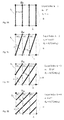
- sections S 1 to S4 which are corresponding sections of polarization layers PL 1 to PL 4 of a polarization rotator module 100 that is configured similarly to the polarization rotator module exemplified in Fig. 2A .
- Sections S 1 to S4, which are respective parts of the polarization layers PL 1 to PL 4 encompass three polarization rotation unit cells UC 1,1 UC 1,2 UC 1,3 , having dimensions A and B along the two lateral axes X and Y respectively.
- the polarization rotator module 100 is configured to filter one of the polarization components of radiation interacting therewith (e.g. filter the component that is parallel to the extinction axis of the first polarizer layer it interacts with (e.g. filter the polarization component parallel to EX 4 ) and also to rotate the polarization of the second polarization component of that radiation (e.g. rotate the polarization component orthogonal to EX 4 ) by a total polarization rotation to angle ⁇ (e.g. so it becomes orthogonal to the extinction axis EX 1 of the last polarizer layer with which the radiation interacts on the way to the antenna array).
- filter the component that is parallel to the extinction axis of the first polarizer layer it interacts with e.g. filter the polarization component parallel to EX 4
- rotate the polarization of the second polarization component of that radiation e.g. rotate the polarization component orthogonal to EX 4
- ⁇ e.g. so it becomes
- the unit cell UC represents the smallest repeatable "building block” sections/structures defined in the polarization rotation module 100.
- the polarization rotator 100 may be regarded as a tightly packed tiling of a plurality of similar such unit cells UC seamlessly "stitched" together.
- unit cell sections can be stitched together to form a continuous wire-grid pattern in the layer, without any discontinuity of the pattern (e.g. of the conductive lines in the pattern) in the border line between adjacent unit cell sections.
- orientation angles ⁇ k of the wire-grid patterns PT k of the respective layers PL k (indexed k). More specifically, according to some embodiments of the present invention the orientation angles are selected in accordance with the desired lateral dimensions of the unit cells (the ratio between them) as in Eq. 1 above. Alternatively or additionally, as the ratio A/B may depend on the number of polarizer layers K and the total angle of polarization rotation ⁇ , the orientation angles ⁇ k may be computed based on these parameters as follows: ⁇ k Tan - 1 ⁇ Tan ⁇ ⁇ k - 1 / K - 1 .
- the total number of polarizer layers K may be selected based on Eq. (2) above in accordance with the desired ratio A/B of the lateral periodicities/ lateral dimensions of the unit cells and the total polarization rotation angle ⁇ .
- the orientation angles ⁇ k may be selected in accordance with Eq. (1) above, based on the desired ratio A/B of the lateral periodicities/ lateral dimensions of the unit cells.
- the number K of polarizer layers may be predetermined in advance.
- K may be a given design parameter, which may be selected to approximate the ratio A/B while also to optimize operation of the polarization rotation in the desired bandwidth ⁇ considering that for wider desired bandwidth ⁇ a higher number K of polarizer layers should preferably be used.
- the orientation angles ⁇ k may be selected in accordance with Eq. (3) above, based on K and on the total polarization rotation angle ⁇ .
- the spacing d k between the conductive lines/wires are also specifically selected to provide that the wire grid patterns PT k , in each of the layers k respectively, are formed as continuous wire-grid patterns across the entire polarization rotation module 100.
- d is a certain predetermined nominal pitch distance of the conductive line and ⁇ k is the orientation angle of the wire-grid polarizer pattern in the respective layer indexed k.
- d is selected to be smaller than the nominal wavelength ⁇ of the radiation whose polarization is to be rotated.
- the pitch distances d k are selected such that the respective wire-grid patterns PT k are all periodic along a certain lateral axis (e.g. X) with spatial periodicity N*d (where N is a certain integer number).
- N is a certain integer number.
- the widths of the W k of conductive lines, in each layer k are typically smaller than the spatial-periodicity/pitch d k of the conductive lines so that the conductive lines are spaced apart from one another. This is in order to reduce the effects of the polarizer layer k on radiation components which are polarized perpendicular to the conductive lines of the layer, while reflecting the radiation components which are polarized parallel to the conductive lines of the layer. To this end, it should be understood that the widths of the W k of conductive lines may be the same or different in different layers k.
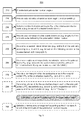
- Fig. 3 is a flow chart 200 of a method for designing a polarization filter module 100 (polarization rotator module) according to the present invention.
- Method 200 includes operations 210 to 290 described forthwith.
- Both 210 and 220 show data indicative of a total polarization rotation angle ⁇ to be applied to radiation interacting with the polarization filter module 100, and data indicative of the nominal wavelength ⁇ of the radiation and possibly also of the bandwidth ⁇ of the radiation wavelength.
- a desired number K of polarizer layers PL k to be implemented in the polarization rotation module 100 is provided/determined.
- the number K may be provided as a predetermined design parameter and/or it may be selected/determined based on the desired bandwidth ⁇ and/or based on the desired dimensions/periodicities A and B of the unit cells.
- the desired lateral dimensions/periodicities A and B of the unit cells' tiling to be defined in the polarization rotation module 100 are determined.
- one of these desired periodicities e.g. the length A or the width B of the unit cells
- the other one of these desired periodicities may be determined in 250 by utilizing the ratio A/B which may be calculated based on Eq. (2) and utilizing ⁇ and K which are provided in operations 210 and 230 above.
- Operations 240 and 250 can be performed before or after operation 230.
- the orientation angles ⁇ k of the patterns of the polarizer layers PL k are determined.
- the orientation angle ⁇ k of the extinction axis of each polarizer layer PL K can be determined according to based on the layer's index k based on Eq. (1) or Eq. (3) above (e.g. utilizing either the desired unit cell dimension ratio A/B or the desired number of layers K as given parameters).
- the pitches d k of the conductive lines/wires in the wire grid patterns PT k of the respective polarizer layers PL k are determined.
- a nominal pitch is provided/selected, typically in accordance with the radiation wavelength; e.g. d ⁇ ⁇
- the pitch d k of the wires/conductive lines in each layer is selected in accordance with the pattern ⁇ k orientation in each layer k (e.g. according to Eq. 4 or 5 above).
- pitches d k of different polarizer layers PL k may have different values, but that accordingly, also the values of the widths W k of conductive lines may be specifically selected/determined in 280 (e.g. based on the respective pitches d k of the corresponding layers k) so as to optimize the operation of the polarization rotation module.
- widths W k of conductive lines may have the same or different values in different layers k.
- the arrangement of the receiving and/or transmitting elements of an antenna array is determined in accordance with the dimensions A and B of the unit cells defined. More specifically the spatial periodicities A' and B' of the receiving and/or transmitting elements of the arrays may be selected according to Eq. (7) as integer multiples of the respective spatial periods A and B of the polarization rotation unit cells.
- the antenna elements are each associated with a certain number of one or more polarization rotator unit cells covering their fields of view (e.g. covering their reception/transmission beams) and located at the same relative positions with respect to the antenna elements associated therewith.
- the radiation module 300 includes a polarization rotation module 100 configured according to an embodiment of the present invention, and an arrangement/array 310 of radiating elements.
- the radiating elements are herein after also referred to as antenna elements or just elements , although it should be understood that types of radiation elements may also be used and are also considered in the scope of the present invention.
- the radiating/antenna elements are arranged/tiled to form different types of a two-dimensional array.
- the antenna elements of the array 310 are arranged in a plane substantially parallel to the plane of the polarization rotator module 100 (namely parallel to the polarizer layers PL k thereof). It should be noted, although not expressly depicted in the figure, that according to some embodiments of the present invention the polarization rotator module 100 is configured with a lateral extent greater than a lateral extent of the arrangement of elements along the two lateral axes X and Y such that the field of view (the reception/transmission beam) of each of the antenna elements (e.g. including those elements located at the margins of the array) is entirely covered by the polarization rotator module 100.
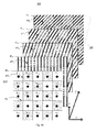
- Fig. 4A illustrates an antenna module 300 including an array 310 of antenna elements E n,m arranged in a rectangular lattice with spatial periodicities A' and B' along the two lateral axes X and Y, and a polarization rotator module 100 configured according to the present invention and accommodated in front of the array 310 of antenna elements E n,m .
- a rectangular lattice RL with periodicities A' and B' along the X and Y axes is illustrated in the figure and its projection onto each of the polarizer layers is also shown. It should be understood that the rectangular lattice RL is not an element of the antenna module 300 but is illustrated in the figure only to serve as a guide to the eye, to illustrate that cells in the lattice "see" similar wire-grid polarizer layer patterns.
- Fig. 4B illustrates an antenna module 300 including an array 310 of antenna elements E n,m arranged in a hexagonal lattice with spatial periodicities A' and B', and a polarization rotator module 100 similar to that of Fig. 4A accommodated in front of the array 310.
- the hexagonal lattice HL is illustrated in the figure together with its projection onto each of the polarizer layers to serve as a guide to the eye.
- the hexagonal lattice HL there are defined two groups of cells respectively accommodating elements E 1 and E 2 , and the elements in each group of cells lattice "see" similar patterns of the wire-grid polarizer layers.
- the antenna elements E1 are all exposed to a similar structure of the polarization rotation module 100 in their fields of view, and in the same way the antenna elements E2 are also all exposed to a similar pattern structure of the polarization rotation module 100.
- utilizing the hexagonal lattice provides that there are two groups of antenna elements wherein the elements of each group experience a similar optical/electrical effect from the polarization rotation module 100.
- a rectangular array of antenna elements ( Fig. 4A ) and a hexagonal array of antenna elements ( Fig. 4B ) are respectively illustrated in conjunction with the polarization rotator module 100.
- the present invention may also be implemented with different types/geometries of arrays of receiving and/or transmitting elements.
- the polarization rotator module 100 may be configured for use with one dimensional arrays or with two dimensional arrays of antenna elements.
- the polarization rotator module 100 may be used with other array geometries (other lattice types) such as triangular or rhombus arrays of antenna elements.
- the polarization rotator module 100 may be used with composite arrays of antenna elements formed as two or more superimposed arrays of elements, where the periodicities A' and B' of each of the superimposed arrays each satisfy Eq. (7) above.
- the antenna elements of each of the superimposed arrays may be laterally shifted, or with respect to the other of the superimposed arrays, by a non-integer number of unit cell periods A and B along the lateral X and Y axes respectively.
- the antenna elements may be considered to belong to different antenna element groups wherein the elements of each group are exposed to similar patterns of the polarization rotation module in their field of view (e.g. each group includes antenna elements of one or more of the superimposed arrays, which are laterally shifted from one another by an integer number of unit cell periods A and B).
- the polarization rotator module 100 or one or more of its polarizer layers PL k may be configured as an integrated structure.
- the polarizer layers PL k may be formed on a dielectric substrate/layer with a plurality of continuous conductive line regions CL k printed on the dielectric substrate/layer.
- the polarization rotator includes one or more spacer layers arranged in between consecutive polarizer layers PL k that are formed on the dielectric substrate.
- the dielectric substrate on which the polarizer layers PL k are implemented may include ceramic material, and/or glass-reinforced epoxy laminate materials, such as FR-4.
- the spacer layers located between adjacent polarizer layers PL k may include structural foam materials such as ROHACELL®. It should be understood that according to some embodiments of the present invention all of the layers of the polarization rotator may be implemented integrally by the integrated structure. Alternatively or additionally, one or more of the polarizer layers, or all of the polarizer layers may be implemented as separate structures and may be fabricated by any suitable technology (e.g. utilizing an integrated structure fabrication technology and/or any other suitable fabrication technology).
- the antenna array 310 may also be configured as an integrated structure, printed on a substrate.
- the antenna array 310 and the polarization rotation module 100 may be integrated together in a single integrated structure including a stack of printed circuit boards including at least one printed circuit layer with the antenna array printed thereon, and one or more printed circuit boards with one or more of said polarizer layers printed thereon.
Landscapes
- Physics & Mathematics (AREA)
- Engineering & Computer Science (AREA)
- General Physics & Mathematics (AREA)
- Theoretical Computer Science (AREA)
- Optics & Photonics (AREA)
- Mathematical Physics (AREA)
- Data Mining & Analysis (AREA)
- General Engineering & Computer Science (AREA)
- Pure & Applied Mathematics (AREA)
- Algebra (AREA)
- Computational Mathematics (AREA)
- Mathematical Analysis (AREA)
- Mathematical Optimization (AREA)
- Databases & Information Systems (AREA)
- Software Systems (AREA)
- Geometry (AREA)
- Evolutionary Computation (AREA)
- Computer Hardware Design (AREA)
- Variable-Direction Aerials And Aerial Arrays (AREA)
- Polarising Elements (AREA)
Applications Claiming Priority (1)
| Application Number | Priority Date | Filing Date | Title |
|---|---|---|---|
| IL232866A IL232866B (en) | 2014-05-29 | 2014-05-29 | Polarization rotator |
Publications (1)
| Publication Number | Publication Date |
|---|---|
| EP2950123A1 true EP2950123A1 (fr) | 2015-12-02 |
Family
ID=53264493
Family Applications (1)
| Application Number | Title | Priority Date | Filing Date |
|---|---|---|---|
| EP15168594.8A Withdrawn EP2950123A1 (fr) | 2014-05-29 | 2015-05-21 | Rotateur de polarisation |
Country Status (4)
| Country | Link |
|---|---|
| US (1) | US10126476B2 (fr) |
| EP (1) | EP2950123A1 (fr) |
| IL (1) | IL232866B (fr) |
| SG (1) | SG10201504056PA (fr) |
Cited By (2)
| Publication number | Priority date | Publication date | Assignee | Title |
|---|---|---|---|---|
| CN107257031A (zh) * | 2017-07-21 | 2017-10-17 | 中国电子科技集团公司第二十九研究所 | 一种极化角度递变的高功率金属极化器 |
| CN110504549A (zh) * | 2019-07-26 | 2019-11-26 | 西安电子科技大学 | 基于石墨烯的吸透一体化频率选择表面 |
Families Citing this family (8)
| Publication number | Priority date | Publication date | Assignee | Title |
|---|---|---|---|---|
| KR102302466B1 (ko) * | 2014-11-11 | 2021-09-16 | 주식회사 케이엠더블유 | 도파관 슬롯 어레이 안테나 |
| US10069211B2 (en) * | 2016-09-16 | 2018-09-04 | The United States Of America As Represented By The Secretary Of The Navy | Broadband circularly polarized patch antenna and method |
| US10347976B2 (en) * | 2016-12-09 | 2019-07-09 | University Of Idaho | Stacked printed circuit board implementations of three dimensional antennas |
| US10840573B2 (en) | 2017-12-05 | 2020-11-17 | The United States Of America, As Represented By The Secretary Of The Air Force | Linear-to-circular polarizers using cascaded sheet impedances and cascaded waveplates |
| US10547117B1 (en) | 2017-12-05 | 2020-01-28 | Unites States Of America As Represented By The Secretary Of The Air Force | Millimeter wave, wideband, wide scan phased array architecture for radiating circular polarization at high power levels |
| US11686813B2 (en) * | 2020-06-30 | 2023-06-27 | Keysight Technologies, Inc. | Free-space polarization adapter |
| CN112636000B (zh) * | 2020-12-08 | 2022-03-25 | 中国人民解放军空军工程大学 | 一种具有红外低发射的超复合材料 |
| US12366693B2 (en) * | 2022-10-12 | 2025-07-22 | Visera Technologies Company Limited | Image sensor |
Citations (4)
| Publication number | Priority date | Publication date | Assignee | Title |
|---|---|---|---|---|
| US2554936A (en) * | 1944-05-18 | 1951-05-29 | Rca Corp | Radio-frequency device |
| EP0795928A2 (fr) * | 1996-03-13 | 1997-09-17 | SPACE ENGINEERING S.p.A. | Antenne à seul ou double réflecteur, à faisceaux conformés et à polarisation linéaire |
| US6788461B2 (en) | 2002-10-15 | 2004-09-07 | Eastman Kodak Company | Wire grid polarizer |
| US20060119937A1 (en) | 2004-12-06 | 2006-06-08 | Moxtek, Inc. | Multilayer wire-grid polarizer |
Family Cites Families (4)
| Publication number | Priority date | Publication date | Assignee | Title |
|---|---|---|---|---|
| JP2008522226A (ja) * | 2004-11-30 | 2008-06-26 | アグーラ テクノロジーズ インコーポレイテッド | 大規模ワイヤ・グリッド偏光子の応用および作製技術 |
| US7961393B2 (en) * | 2004-12-06 | 2011-06-14 | Moxtek, Inc. | Selectively absorptive wire-grid polarizer |
| US8611007B2 (en) * | 2010-09-21 | 2013-12-17 | Moxtek, Inc. | Fine pitch wire grid polarizer |
| US8913320B2 (en) * | 2011-05-17 | 2014-12-16 | Moxtek, Inc. | Wire grid polarizer with bordered sections |
-
2014
- 2014-05-29 IL IL232866A patent/IL232866B/en active IP Right Grant
-
2015
- 2015-05-21 EP EP15168594.8A patent/EP2950123A1/fr not_active Withdrawn
- 2015-05-21 US US14/719,101 patent/US10126476B2/en active Active
- 2015-05-22 SG SG10201504056PA patent/SG10201504056PA/en unknown
Patent Citations (4)
| Publication number | Priority date | Publication date | Assignee | Title |
|---|---|---|---|---|
| US2554936A (en) * | 1944-05-18 | 1951-05-29 | Rca Corp | Radio-frequency device |
| EP0795928A2 (fr) * | 1996-03-13 | 1997-09-17 | SPACE ENGINEERING S.p.A. | Antenne à seul ou double réflecteur, à faisceaux conformés et à polarisation linéaire |
| US6788461B2 (en) | 2002-10-15 | 2004-09-07 | Eastman Kodak Company | Wire grid polarizer |
| US20060119937A1 (en) | 2004-12-06 | 2006-06-08 | Moxtek, Inc. | Multilayer wire-grid polarizer |
Non-Patent Citations (3)
| Title |
|---|
| AMIDROR I ET AL: "ANALYSIS OF THE MICROSTRUCTURES (ROSETTES) IN THE SUPERPOSITION OF PERIODIC LAYERS", JOURNAL OF ELECTRONIC IMAGING, SPIE / IS & T, 1000 20TH ST. BELLINGHAM WA 98225-6705 USA, vol. 11, no. 3, 1 July 2002 (2002-07-01), pages 316 - 337, XP001122627, ISSN: 1017-9909, DOI: 10.1117/1.1477442 * |
| LECH R ET AL: "Analysis and Design of a Polarizer Rotator System", IEEE TRANSACTIONS ON ANTENNAS AND PROPAGATION, IEEE SERVICE CENTER, PISCATAWAY, NJ, US, vol. 56, no. 3, 1 March 2008 (2008-03-01), pages 844 - 847, XP011205474, ISSN: 0018-926X * |
| TORRES R P ET AL: "ANALYSIS AND DESIGN OF A TWO-OCTAVE POLARIZATION ROTATOR FOR MICROWAVE FREQUENCY", IEEE TRANSACTIONS ON ANTENNAS AND PROPAGATION, IEEE SERVICE CENTER, PISCATAWAY, NJ, US, vol. 41, no. 2, 1 February 1993 (1993-02-01), pages 208 - 213, XP000303628, ISSN: 0018-926X, DOI: 10.1109/8.214612 * |
Cited By (3)
| Publication number | Priority date | Publication date | Assignee | Title |
|---|---|---|---|---|
| CN107257031A (zh) * | 2017-07-21 | 2017-10-17 | 中国电子科技集团公司第二十九研究所 | 一种极化角度递变的高功率金属极化器 |
| CN110504549A (zh) * | 2019-07-26 | 2019-11-26 | 西安电子科技大学 | 基于石墨烯的吸透一体化频率选择表面 |
| CN110504549B (zh) * | 2019-07-26 | 2020-11-03 | 西安电子科技大学 | 基于石墨烯的吸透一体化频率选择表面 |
Also Published As
| Publication number | Publication date |
|---|---|
| US10126476B2 (en) | 2018-11-13 |
| IL232866B (en) | 2020-08-31 |
| US20150349431A1 (en) | 2015-12-03 |
| SG10201504056PA (en) | 2015-12-30 |
Similar Documents
| Publication | Publication Date | Title |
|---|---|---|
| US10126476B2 (en) | Polarization rotator | |
| Wen et al. | Subwavelength photonic band gaps from planar fractals | |
| JP2022520700A (ja) | 1つまたは複数のメタマテリアル構造に基づくアンテナアレイ | |
| JP4990188B2 (ja) | 反射板 | |
| US10749265B2 (en) | Surface wave polarization converter | |
| US9620862B2 (en) | Reflectarray | |
| US10466569B2 (en) | Beam steering device, optical apparatus including beam steering device, and beam steering method | |
| US10270180B2 (en) | Antenna apparatus | |
| US10840573B2 (en) | Linear-to-circular polarizers using cascaded sheet impedances and cascaded waveplates | |
| US20150229031A1 (en) | Electromagnetic Absorber | |
| CN103996905A (zh) | 一种极化可控多功能微波器件 | |
| US7602337B2 (en) | Antenna array including a phase shifter array controller and algorithm for steering the array | |
| WO2018234533A1 (fr) | Réseau d'antennes à bande large | |
| JP4926099B2 (ja) | 電磁波反射面 | |
| KR20180065788A (ko) | 패브리-페로 광각 공진기 | |
| US9397408B2 (en) | Antenna array | |
| WO2010127347A2 (fr) | Structure de réseau pour séparer la lumière | |
| CN102751579B (zh) | 分离电磁波束的超材料 | |
| JP5938012B2 (ja) | 反射板及びアンテナ装置 | |
| KR102328062B1 (ko) | 넓은 대역폭 및 고효율의 평면형 메타표면 역반사체 | |
| JP7290588B2 (ja) | メタサーフェス反射板 | |
| EP2923415B1 (fr) | Antenne de guide d'onde à fentes polarisée de manière circulaire | |
| RU2291453C1 (ru) | Способ уменьшения эффективной поверхности рассеяния антенн и устройство его реализации | |
| JP7845076B2 (ja) | ミリ波反射板 | |
| Geschke et al. | Surface wave mitigation based on finite EBG structures for W-band radar millimetre-wave MIMO antenna arrays |
Legal Events
| Date | Code | Title | Description |
|---|---|---|---|
| AK | Designated contracting states |
Kind code of ref document: A1 Designated state(s): AL AT BE BG CH CY CZ DE DK EE ES FI FR GB GR HR HU IE IS IT LI LT LU LV MC MK MT NL NO PL PT RO RS SE SI SK SM TR |
|
| AX | Request for extension of the european patent |
Extension state: BA ME |
|
| PUAI | Public reference made under article 153(3) epc to a published international application that has entered the european phase |
Free format text: ORIGINAL CODE: 0009012 |
|
| 17P | Request for examination filed |
Effective date: 20160526 |
|
| RBV | Designated contracting states (corrected) |
Designated state(s): AL AT BE BG CH CY CZ DE DK EE ES FI FR GB GR HR HU IE IS IT LI LT LU LV MC MK MT NL NO PL PT RO RS SE SI SK SM TR |
|
| STAA | Information on the status of an ep patent application or granted ep patent |
Free format text: STATUS: EXAMINATION IS IN PROGRESS |
|
| 17Q | First examination report despatched |
Effective date: 20191007 |
|
| STAA | Information on the status of an ep patent application or granted ep patent |
Free format text: STATUS: THE APPLICATION IS DEEMED TO BE WITHDRAWN |
|
| 18D | Application deemed to be withdrawn |
Effective date: 20220119 |