EP2950134A1 - Lentille à DEL et système d'éclairage pour lampe à DEL - Google Patents
Lentille à DEL et système d'éclairage pour lampe à DEL Download PDFInfo
- Publication number
- EP2950134A1 EP2950134A1 EP14199088.7A EP14199088A EP2950134A1 EP 2950134 A1 EP2950134 A1 EP 2950134A1 EP 14199088 A EP14199088 A EP 14199088A EP 2950134 A1 EP2950134 A1 EP 2950134A1
- Authority
- EP
- European Patent Office
- Prior art keywords
- light
- optical axis
- light emitting
- led
- led lens
- Prior art date
- Legal status (The legal status is an assumption and is not a legal conclusion. Google has not performed a legal analysis and makes no representation as to the accuracy of the status listed.)
- Withdrawn
Links
Images


Classifications
-
- F—MECHANICAL ENGINEERING; LIGHTING; HEATING; WEAPONS; BLASTING
- F21—LIGHTING
- F21V—FUNCTIONAL FEATURES OR DETAILS OF LIGHTING DEVICES OR SYSTEMS THEREOF; STRUCTURAL COMBINATIONS OF LIGHTING DEVICES WITH OTHER ARTICLES, NOT OTHERWISE PROVIDED FOR
- F21V5/00—Refractors for light sources
- F21V5/04—Refractors for light sources of lens shape
-
- F—MECHANICAL ENGINEERING; LIGHTING; HEATING; WEAPONS; BLASTING
- F21—LIGHTING
- F21K—NON-ELECTRIC LIGHT SOURCES USING LUMINESCENCE; LIGHT SOURCES USING ELECTROCHEMILUMINESCENCE; LIGHT SOURCES USING CHARGES OF COMBUSTIBLE MATERIAL; LIGHT SOURCES USING SEMICONDUCTOR DEVICES AS LIGHT-GENERATING ELEMENTS; LIGHT SOURCES NOT OTHERWISE PROVIDED FOR
- F21K9/00—Light sources using semiconductor devices as light-generating elements, e.g. using light-emitting diodes [LED] or lasers
- F21K9/60—Optical arrangements integrated in the light source, e.g. for improving the colour rendering index or the light extraction
-
- F—MECHANICAL ENGINEERING; LIGHTING; HEATING; WEAPONS; BLASTING
- F21—LIGHTING
- F21V—FUNCTIONAL FEATURES OR DETAILS OF LIGHTING DEVICES OR SYSTEMS THEREOF; STRUCTURAL COMBINATIONS OF LIGHTING DEVICES WITH OTHER ARTICLES, NOT OTHERWISE PROVIDED FOR
- F21V7/00—Reflectors for light sources
- F21V7/04—Optical design
-
- G—PHYSICS
- G02—OPTICS
- G02B—OPTICAL ELEMENTS, SYSTEMS OR APPARATUS
- G02B19/00—Condensers, e.g. light collectors or similar non-imaging optics
- G02B19/0004—Condensers, e.g. light collectors or similar non-imaging optics characterised by the optical means employed
- G02B19/0028—Condensers, e.g. light collectors or similar non-imaging optics characterised by the optical means employed refractive and reflective surfaces, e.g. non-imaging catadioptric systems
-
- G—PHYSICS
- G02—OPTICS
- G02B—OPTICAL ELEMENTS, SYSTEMS OR APPARATUS
- G02B19/00—Condensers, e.g. light collectors or similar non-imaging optics
- G02B19/0033—Condensers, e.g. light collectors or similar non-imaging optics characterised by the use
- G02B19/0047—Condensers, e.g. light collectors or similar non-imaging optics characterised by the use for use with a light source
- G02B19/0061—Condensers, e.g. light collectors or similar non-imaging optics characterised by the use for use with a light source the light source comprising a LED
-
- G—PHYSICS
- G02—OPTICS
- G02B—OPTICAL ELEMENTS, SYSTEMS OR APPARATUS
- G02B27/00—Optical systems or apparatus not provided for by any of the groups G02B1/00 - G02B26/00, G02B30/00
- G02B27/09—Beam shaping, e.g. changing the cross-sectional area, not otherwise provided for
- G02B27/0938—Using specific optical elements
- G02B27/095—Refractive optical elements
- G02B27/0955—Lenses
-
- H—ELECTRICITY
- H10—SEMICONDUCTOR DEVICES; ELECTRIC SOLID-STATE DEVICES NOT OTHERWISE PROVIDED FOR
- H10H—INORGANIC LIGHT-EMITTING SEMICONDUCTOR DEVICES HAVING POTENTIAL BARRIERS
- H10H20/00—Individual inorganic light-emitting semiconductor devices having potential barriers, e.g. light-emitting diodes [LED]
- H10H20/80—Constructional details
- H10H20/85—Packages
- H10H20/855—Optical field-shaping means, e.g. lenses
-
- F—MECHANICAL ENGINEERING; LIGHTING; HEATING; WEAPONS; BLASTING
- F21—LIGHTING
- F21W—INDEXING SCHEME ASSOCIATED WITH SUBCLASSES F21K, F21L, F21S and F21V, RELATING TO USES OR APPLICATIONS OF LIGHTING DEVICES OR SYSTEMS
- F21W2131/00—Use or application of lighting devices or systems not provided for in codes F21W2102/00-F21W2121/00
- F21W2131/40—Lighting for industrial, commercial, recreational or military use
-
- F—MECHANICAL ENGINEERING; LIGHTING; HEATING; WEAPONS; BLASTING
- F21—LIGHTING
- F21Y—INDEXING SCHEME ASSOCIATED WITH SUBCLASSES F21K, F21L, F21S and F21V, RELATING TO THE FORM OR THE KIND OF THE LIGHT SOURCES OR OF THE COLOUR OF THE LIGHT EMITTED
- F21Y2115/00—Light-generating elements of semiconductor light sources
- F21Y2115/10—Light-emitting diodes [LED]
Definitions
- the present application relates to lighting devices, and more particularly to an LED lens and an illumination system for LED lamp.
- the popular halogen apparatus presents the following drawbacks, such as relatively high power consumption, inefficiency of light dispersion due to the placement of its metal shield in the line sight of the halogen bulb, and its limited effectiveness in preventing glare from the halogen bulb.
- LED lighting apparatuses have been designed to replace the halogen apparatus, as well as other traditional incandescent or fluorescence lighting apparatuses.
- the LED lighting apparatuses are used in the super market, exhibition hall, museum, and so on because of long-life and energy-saving thereof.
- the LED light apparatuses must light up two rows of goods. At the same time, it cannot glare eyes of the customers when they select goods or browse through the market.
- An LED lens includes an optical axis, a first light emitting surface, a second light emitting surface which only has one intersecting line with the first light emitting surface, a light source recess arranged through the optical axis, and a critical reflection surface disposed between the first, second light emitting surfaces and the light source recess.
- the intersecting line is perpendicularly intersect with the optical axis.
- the first, second light emitting surfaces receive the light emitted from the light source recess and the critical reflection surface and directly emit the receiving light. An emergent light of the first light emitting surface is separated from that of the second light emitting surface.
- a LED lens includes an optical axis, a V-shaped groove, a light source recess arranged through the optical axis, and a critical reflection surface arranged between the V-shaped groove and the light source recess.
- Two sides of the V-shaped groove is symmetrical with the optical axis as the axis of symmetry. The two sides of the V-shaped groove receive the light emitted from the light source recess and the critical reflection surface and directly emit the received light. An emergent light of one side of the V-shaped groove is separated from that of another.
- An illumination system for LED lamp includes at least one LED lens described above, and at least one illumination area arranged in lighting direction of the LED lens.
- the LED lens has the first, second light emitting surfaces and the emergent light of the first light emitting surface is separated from that of the second light emitting surface, the light emitted from the first, second light emitting surfaces illuminate towards the direction which is far away from the optical axis.
- the illumination system for LED lamp not only light up two rows of goods but also it has no light glaring people's eyes.
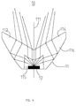
- the illumination system for LED lamp 100 includes at least one LED module 10, and at least one illumination area 20 arranged in a lighting direction of the LED module 10.
- the illumination system for LED lamp 100 includes two illumination areas 20.
- the two illumination areas 20 are respectively mounted on two side of an optical axis of the LED module 10.
- the illumination system for LED lamp 100 may only includes one illumination area 20.
- the single illumination area 20 must mount on one side of the optical axis of the LED module 10 which locates in the lighting direction thereof.
- the illumination system for LED lamp 100 may includes a plurality of rows of the LED modules 10.
- each of rows of the LED modules 10 may includes a plurality of LED lamp, which depends on the length or area of the illumination area 20.
- the illumination system for LED lamp 100 further includes other functional components, such as housing for mounting the LED module 10, cover, power for supplying power for the LED module 10, and so on, which need not to be described in detail.
- the LED module 10 includes an LED chip 12, and an LED lens 11 arranged on light path of the LED chip 12.
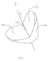
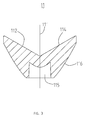
- the LED lens 11 includes an optical axis 111, a first light emitting surface 112, a second light emitting surface 114 which only has one intersecting ling 113 with the first light emitting surface 112, a light source recess 115 arranged through the optical axis 111, and a critical reflection surface 116 disposed between the first, second light emitting surfaces 112, 114 and the light source recess 115.
- the optical axis 111 is a universal feature for all of lens and used to dispose the light source, namely the LED chip 12. Moreover, the optical axis 111 is a guide for optic design.
- first light emitting surface 112 has same structure, shape, luminous theory, and light path with the second light emitting surface 114, only the first light emitting surface 112 is described in detail as a example.
- the first, second light emitting surfaces 112, 114 are not at the same level and intersect with each other and only have a intersecting line 113 therebetween.
- the first, second light emitting surfaces 112, 114 receive the light emitted from the light source recess 115 and the critical reflection surface 116 and directly emitting the received light. That is to say, the first, second light emitting surfaces 112, 114 not distribute the received light, such as reflecting, and directly emit it towards the illumination area 20.
- the first, second light emitting surfaces 112, 114 form a V-shaped groove.
- Two sides of the V-shaped groove, namely the first, second light emitting surfaces 112, 114, are symmetrical with the optical axis 111 as the axis of symmetry. As is described above, the two sides of the V-shaped groove receive the light emitted from the light source recess 115 and the critical reflection surface 116 and directly emit it towards the illumination area 20.
- first, second light emitting surfaces 112, 114 or the two sides of the V-shaped groove directly emit the received light, an emergent light of the first light emitting surface 112 is separated from that of the second light emitting surface 114. That is to say, the lights emitted from the first light emitting surface 112 do not intersect with that emitted from the second light emitting surface 14. Similarly, an emergent light of one side of the V-shaped groove is separated from that of another.
- the intersecting line 113 is formed between the first light emitting surface 112 and the second light emitting surface 114.
- the intersecting line 113 is perpendicular to and intersects with the optical axis 111 so as that the first light emitting surface 112 has same structure, shape, luminous theory, and light path with the second light emitting surface 114.
- the light source recess 115 is used for mounting the light source, such as the LED chip 12, or other traditional light source.
- the light source is the LED chip 12.
- the light source may be other traditional light source, such as incandescent or fluorescence lighting apparatuses, and so on.
- the LED chip 12 may be mounted into the light source recess 115 or at outer side of the light source recess 115.
- a bottom side of the LED chip 12 is flush with an end of the light source recess 115 for sufficiently taking advantage of the light emitted forward of the LED chip 12 and ease to assemble the LED lens 11 and the LED chip 12.
- a light emitting side of the LED chip 12 is flush with the end of the light source recess 115 for sufficiently taking advantage of the light emitted forward of the LED chip 12.
- the bottom side of the LED chip 12 is flush with the end of the light source recess 115.
- the light source recess 115 has a different configuration as difference of the whole LED lens 11. As shown in FIG.
- the LED lens 11 when the LED lens 11 is a revolution body, that is to say, it is a cone that is centered on the optical axis 111, the light source recess 115 is a hollow cylinder, and the surface intersecting with the optical axis 111 is a convex lens.
- the convex lens is configured for making the lighting direction therefrom is parallel to the optical axis 111.
- the light source recess 115 when the LED lens 11 is an elongate body, the light source recess 115 is an elongate slot and the surface intersecting with the optical axis 111 is a convex surface for making the lighting direction therefrom parallel to the optical axis111.
- the cone or the elongate LED lens can be used in different occasion. For example, the cone LED lens may be used at corner which has little space and the elongate LED lens may be used at large-scale market for assembling a plurality of LED chips 12.
- the critical reflection surface 116 is formed an inclined surface like a mortar to receiving the light emitted from the side wall of the light source recess 115 and reflecting the light into the first light emitting surface 112 and the second light emitting surface 114 according to the law of total reflection.
- one end of a profile of the critical reflection surface 116 connects to the first, second light emitting surfaces 112 and another connects to the free end of the light source recess 115.
- the critical reflection surface 116 can receive all of light emitted from the side wall of the light source recess 115.
- the critical reflection surface 116 has a different configuration as difference of shape of the light source recess 115.
- the critical reflection surface 116 is a revolution surface that is centered on the optical axis 111.
- the critical reflection surface 116 is an extension surface which extends along the intersecting line 113 which is perpendicular to the optical axis 112.
- the first, second light emitting surfaces 112, 114 receive part of the light reflected from the critical reflection surface 116 and have respectively an arc-shaped configuration which is concaved along a direction towards the critical reflection surface 116.
- the LED chip 12 is a semiconductor light source and transforms power into light.
- the LED chip 12 presents many advantages over traditional light sources including lower energy consumption, longer lifetime, improved physical robustness, smaller size, and faster switching.
- the light source recess 115 is the hollow cylinder, a center of the LED chip 12 is arranged on the optical axis 111 of the LED lens 11 for ease to optic design.
- the optical axis of the LED chip 12 functions as and regards as one optical axis 111 of the LED lens 11.
- the illuminated area 20 is an object illuminated by the LED module 10 and may be a plan or a curve.
- the illuminated area 20 is a plan and may be a picture exhibited in museum or selling goods placing in the freezer of supermarket, and so on.
- the beam angle means that an angle between two directions in which light intensity is equal to 50% of maximum light intensity of the LED chip 12 in a cross section along the optical axis of the LED chip 12. Therefore, if the distance between the illumination area 20 and the optical axis 111 of the LED lens 11 is X, the minimum distance between the illumination area 20 and the LED lens 11 is h. If the minimum distance between the illumination area 20 and the LED lens 11 is less than h, part of the illumination area 20 cannot be illuminated. And if the minimum distance between the illumination area 20 and the LED lens 11 is greater than h, part of light emitted from the LED lens 11 may be wasted.
- the two illumination area 20 should be respectively mounted in two symmetric sides of the intersecting line 113 of the first, second light emitting surface 112, 115 or an intersecting line of the V-shaped groove.
- the LED lens 11 has the first, second light emitting surfaces 112, 114 and the emergent light of the first light emitting surface 112 is separated from that of the second light emitting surface 114, the light emitted from the first, second light emitting surfaces 112, 114 illuminate towards the direction which is far away from the optical axis 111.
- the illumination system for LED lamp 100 not only light up two rows of goods but also it has no light glaring people's eyes.
Landscapes
- Physics & Mathematics (AREA)
- Optics & Photonics (AREA)
- Engineering & Computer Science (AREA)
- General Physics & Mathematics (AREA)
- General Engineering & Computer Science (AREA)
- Microelectronics & Electronic Packaging (AREA)
- Non-Portable Lighting Devices Or Systems Thereof (AREA)
Applications Claiming Priority (1)
| Application Number | Priority Date | Filing Date | Title |
|---|---|---|---|
| CN201410240806.8A CN105202479B (zh) | 2014-05-30 | 2014-05-30 | 一种led透镜及灯具照明系统 |
Publications (1)
| Publication Number | Publication Date |
|---|---|
| EP2950134A1 true EP2950134A1 (fr) | 2015-12-02 |
Family
ID=52146228
Family Applications (1)
| Application Number | Title | Priority Date | Filing Date |
|---|---|---|---|
| EP14199088.7A Withdrawn EP2950134A1 (fr) | 2014-05-30 | 2014-12-19 | Lentille à DEL et système d'éclairage pour lampe à DEL |
Country Status (3)
| Country | Link |
|---|---|
| US (1) | US20150345738A1 (fr) |
| EP (1) | EP2950134A1 (fr) |
| CN (1) | CN105202479B (fr) |
Cited By (2)
| Publication number | Priority date | Publication date | Assignee | Title |
|---|---|---|---|---|
| CN111442213A (zh) * | 2020-04-10 | 2020-07-24 | 宁波贝克照明电器有限公司 | 一种照明、氛围一体灯 |
| EP3564580A4 (fr) * | 2017-02-15 | 2020-07-29 | Opple Lighting Co., Ltd. | Appareil de réflexion, module de source de lumière et appareil d'éclairage |
Families Citing this family (7)
| Publication number | Priority date | Publication date | Assignee | Title |
|---|---|---|---|---|
| CN106764682B (zh) * | 2016-12-22 | 2023-10-20 | 赛尔富电子有限公司 | 一种货架标示牌led条形灯 |
| WO2018228207A1 (fr) * | 2017-06-13 | 2018-12-20 | 苏州欧普照明有限公司 | Élément optique et appareil d'éclairage utilisant l'élément optique |
| CN107166334B (zh) * | 2017-06-13 | 2021-12-21 | 苏州欧普照明有限公司 | 一种光学元件及应用该光学元件的照明装置 |
| USD927037S1 (en) | 2018-05-04 | 2021-08-03 | Abl Ip Holding Llc | Symmetric linear optic |
| CA3042310C (fr) | 2018-05-04 | 2021-06-08 | Abl Ip Holding Llc | Appareils optiques destines a l'eclairage d'allee |
| DE102018118684A1 (de) * | 2018-08-01 | 2020-02-06 | Ledlenser GmbH & Co. KG | Optischer Kollimator |
| CN113864698A (zh) * | 2021-10-20 | 2021-12-31 | 赛尔富电子有限公司 | 一种顶部照明灯具 |
Citations (3)
| Publication number | Priority date | Publication date | Assignee | Title |
|---|---|---|---|---|
| US20100296283A1 (en) * | 2009-05-22 | 2010-11-25 | Elliptipar | Total internal reflective (tir) optic light assembly |
| EP2287653A1 (fr) * | 2009-08-20 | 2011-02-23 | Panasonic Electric Works Co., Ltd | Lentille optique et accessoire d'éclairage l'utilisant |
| EP2708806A1 (fr) * | 2012-09-13 | 2014-03-19 | Wanjiong Lin | Lentille, module de DEL et système d'éclairage équipé de celui-ci |
Family Cites Families (6)
| Publication number | Priority date | Publication date | Assignee | Title |
|---|---|---|---|---|
| US7222995B1 (en) * | 2006-01-19 | 2007-05-29 | Bayco Products, Ltd. | Unitary reflector and lens combination for a light emitting device |
| US20100135036A1 (en) * | 2008-12-02 | 2010-06-03 | Harison Toshiba Lighting Corp. | Vehicle lighting device |
| US8324790B1 (en) * | 2011-06-07 | 2012-12-04 | Wen-Sung Hu | High illumination LED bulb with full emission angle |
| CN103322503B (zh) * | 2012-03-19 | 2016-09-07 | 展晶科技(深圳)有限公司 | 光学透镜和使用该光学透镜的发光二极管灯源装置 |
| CN103968326B (zh) * | 2013-01-31 | 2018-04-24 | 欧司朗有限公司 | 透镜和具有该透镜的照明装置 |
| CN203857407U (zh) * | 2014-05-30 | 2014-10-01 | 宁波高新区赛尔富电子有限公司 | 一种led透镜及灯具照明系统 |
-
2014
- 2014-05-30 CN CN201410240806.8A patent/CN105202479B/zh active Active
- 2014-12-19 EP EP14199088.7A patent/EP2950134A1/fr not_active Withdrawn
-
2015
- 2015-04-01 US US14/676,512 patent/US20150345738A1/en not_active Abandoned
Patent Citations (3)
| Publication number | Priority date | Publication date | Assignee | Title |
|---|---|---|---|---|
| US20100296283A1 (en) * | 2009-05-22 | 2010-11-25 | Elliptipar | Total internal reflective (tir) optic light assembly |
| EP2287653A1 (fr) * | 2009-08-20 | 2011-02-23 | Panasonic Electric Works Co., Ltd | Lentille optique et accessoire d'éclairage l'utilisant |
| EP2708806A1 (fr) * | 2012-09-13 | 2014-03-19 | Wanjiong Lin | Lentille, module de DEL et système d'éclairage équipé de celui-ci |
Cited By (3)
| Publication number | Priority date | Publication date | Assignee | Title |
|---|---|---|---|---|
| EP3564580A4 (fr) * | 2017-02-15 | 2020-07-29 | Opple Lighting Co., Ltd. | Appareil de réflexion, module de source de lumière et appareil d'éclairage |
| CN111442213A (zh) * | 2020-04-10 | 2020-07-24 | 宁波贝克照明电器有限公司 | 一种照明、氛围一体灯 |
| CN111442213B (zh) * | 2020-04-10 | 2021-12-14 | 宁波贝克照明电器有限公司 | 一种照明、氛围一体灯 |
Also Published As
| Publication number | Publication date |
|---|---|
| CN105202479A (zh) | 2015-12-30 |
| US20150345738A1 (en) | 2015-12-03 |
| CN105202479B (zh) | 2019-01-18 |
Similar Documents
| Publication | Publication Date | Title |
|---|---|---|
| EP2950134A1 (fr) | Lentille à DEL et système d'éclairage pour lampe à DEL | |
| US8911118B2 (en) | Lens, LED module and illumination system having same | |
| US9360169B2 (en) | Lens, LED module and illumination system with asymmetric lighting distribution | |
| US10156328B2 (en) | LED bar lighting and exhibition cabinet having same | |
| US9377166B2 (en) | Lens, LED module and illumination system having same | |
| US9255669B2 (en) | Lens, LED module and illumination system having same | |
| US10534186B2 (en) | Lens strip, LED wall washer with lens strip | |
| US20160377258A1 (en) | Spread light lens and led strip lights having same | |
| US9518705B2 (en) | Lens and an illumination device having the lens | |
| EP3323318A1 (fr) | Lampe à filament à del | |
| US20160281956A1 (en) | Spread light lens and led strip lights having same | |
| US8267565B2 (en) | LED illumination device and LED illumination module for generating uniform stripped light source | |
| US9052071B2 (en) | Illumination device having light-guiding structure | |
| EP2869106A1 (fr) | Lentille et module de DEL ayant celui-ci | |
| US10598340B2 (en) | LED lamp light distribution system and illumination system | |
| EP3339728A1 (fr) | Lampe à bandes de del pour une étiquette d'un shevle | |
| EP3260767B1 (fr) | Barre à del à éclairage uniforme | |
| EP2960569B1 (fr) | Éclairage à DEL à double rangée de type barre | |
| JP6497501B2 (ja) | 発光装置 | |
| EP3404316B1 (fr) | Système de distribution de lumière d'une lampe à del | |
| CN203099686U (zh) | 透镜、led模组及使用该led模组的照明系统 | |
| CN105326269A (zh) | 一种用于展览柜内的组合式led面板灯 |
Legal Events
| Date | Code | Title | Description |
|---|---|---|---|
| AK | Designated contracting states |
Kind code of ref document: A1 Designated state(s): AL AT BE BG CH CY CZ DE DK EE ES FI FR GB GR HR HU IE IS IT LI LT LU LV MC MK MT NL NO PL PT RO RS SE SI SK SM TR |
|
| AX | Request for extension of the european patent |
Extension state: BA ME |
|
| PUAI | Public reference made under article 153(3) epc to a published international application that has entered the european phase |
Free format text: ORIGINAL CODE: 0009012 |
|
| 17P | Request for examination filed |
Effective date: 20160602 |
|
| RBV | Designated contracting states (corrected) |
Designated state(s): AL AT BE BG CH CY CZ DE DK EE ES FI FR GB GR HR HU IE IS IT LI LT LU LV MC MK MT NL NO PL PT RO RS SE SI SK SM TR |
|
| STAA | Information on the status of an ep patent application or granted ep patent |
Free format text: STATUS: EXAMINATION IS IN PROGRESS |
|
| 17Q | First examination report despatched |
Effective date: 20190228 |
|
| STAA | Information on the status of an ep patent application or granted ep patent |
Free format text: STATUS: THE APPLICATION HAS BEEN WITHDRAWN |
|
| 18W | Application withdrawn |
Effective date: 20190618 |