EP2950232A1 - Identifizierung von Anlagen - Google Patents
Identifizierung von Anlagen Download PDFInfo
- Publication number
- EP2950232A1 EP2950232A1 EP14175992.8A EP14175992A EP2950232A1 EP 2950232 A1 EP2950232 A1 EP 2950232A1 EP 14175992 A EP14175992 A EP 14175992A EP 2950232 A1 EP2950232 A1 EP 2950232A1
- Authority
- EP
- European Patent Office
- Prior art keywords
- piece
- stimulation
- asset
- response
- communication unit
- Prior art date
- Legal status (The legal status is an assumption and is not a legal conclusion. Google has not performed a legal analysis and makes no representation as to the accuracy of the status listed.)
- Withdrawn
Links
Images




Classifications
-
- G—PHYSICS
- G01—MEASURING; TESTING
- G01N—INVESTIGATING OR ANALYSING MATERIALS BY DETERMINING THEIR CHEMICAL OR PHYSICAL PROPERTIES
- G01N21/00—Investigating or analysing materials by the use of optical means, i.e. using sub-millimetre waves, infrared, visible or ultraviolet light
- G01N21/62—Systems in which the material investigated is excited whereby it emits light or causes a change in wavelength of the incident light
-
- G—PHYSICS
- G06—COMPUTING OR CALCULATING; COUNTING
- G06F—ELECTRIC DIGITAL DATA PROCESSING
- G06F21/00—Security arrangements for protecting computers, components thereof, programs or data against unauthorised activity
- G06F21/70—Protecting specific internal or peripheral components, in which the protection of a component leads to protection of the entire computer
- G06F21/71—Protecting specific internal or peripheral components, in which the protection of a component leads to protection of the entire computer to assure secure computing or processing of information
- G06F21/73—Protecting specific internal or peripheral components, in which the protection of a component leads to protection of the entire computer to assure secure computing or processing of information by creating or determining hardware identification, e.g. serial numbers
-
- G—PHYSICS
- G01—MEASURING; TESTING
- G01N—INVESTIGATING OR ANALYSING MATERIALS BY DETERMINING THEIR CHEMICAL OR PHYSICAL PROPERTIES
- G01N27/00—Investigating or analysing materials by the use of electric, electrochemical, or magnetic means
-
- G—PHYSICS
- G01—MEASURING; TESTING
- G01N—INVESTIGATING OR ANALYSING MATERIALS BY DETERMINING THEIR CHEMICAL OR PHYSICAL PROPERTIES
- G01N29/00—Investigating or analysing materials by the use of ultrasonic, sonic or infrasonic waves; Visualisation of the interior of objects by transmitting ultrasonic or sonic waves through the object
- G01N29/34—Generating the ultrasonic, sonic or infrasonic waves, e.g. electronic circuits specially adapted therefor
Definitions
- the present invention relates to the field of identification of assets, in particular to a device for identifying an asset, an asset comprising such a device, an identification system, a method of identifying an asset, and a computer program.
- identification numbers or serial numbers are also stored by some manufacturers in electronically readable storage devices that are attached to the item.
- identification numbers are also stored by some manufacturers in electronically readable storage devices that are attached to the item.
- the item to be identified may receive a completely different electronic identity. This may result in a change of ownership or a change of the item's value or a change of accessible features.
- a device for identifying an asset comprises (a) a piece of material having predetermined physical properties, the piece of material being adapted to be irreversibly attached to the asset, (b) a stimulation and measurement unit attached to the piece of material, the stimulation and measurement unit being adapted to apply a predetermined stimulation to the piece of material and to measure a corresponding response from the piece of material, (c) an analysis unit adapted to analyze the measured response from the piece of material, and (d) a communication unit adapted to output data representative of the analysis of the measured response.
- This aspect is based on the idea that a piece of material having predetermined physical properties and capable of being irreversibly attached to the asset, i.e. as an integral part of the asset, is subjected to a predetermined stimulation.
- the corresponding response which is determined by the specific physical properties of the piece of material and the stimulation, is measured and analyzed, and data representative of the analysis is output through a communication unit.
- the unique combination of physical properties and stimulation provides a unique root identity for the asset when the piece of material is irreversibly attached.
- the term "irreversibly attached” may particularly denote that the piece of material is attached to the asset is such a manner that it cannot be removed without damaging the piece of material and/or the asset.
- the piece of material may be irreversibly attached by welding, gluing, laminating or another similar process.
- predetermined physical properties may particularly denote acoustical, optical or electrical properties.
- the piece of material may comprise metal, such as cast iron, composite material or a combination thereof.
- the predetermined physical properties of the material may be caused by production specific material irregularities, such as random processing variations or deliberate processing of the material. The latter may involve laser based processing, forging and tempering steps.
- the term "apply a predetermined stimulation” may particularly denote that the piece of material is exhibited to a certain physical influence.
- corresponding response from the piece of material may particularly denote a reaction in or from the material caused by the stimulation.
- the analysis performed by the analysis unit may in particular involve determination of a set of characteristic features of the response, such as characteristic features relating to a time response or a frequency response.
- the characteristic features may provide a "fingerprint" characteristic of the combination of material and stimulation.
- Data representing such a "fingerprint” may be processed in a similar way, e.g. by pattern matching, as it is known in the field of biometric systems in order to determine identity and/or authenticity of the asset.
- the communication unit is preferably a data interface capable of communicating with an external system that aims at determining the identity of the asset or at verifying the authenticity of the asset.
- the communication unit may be designed to perform wired or wireless communication with such an external system, either directly or through an internal communication system or bus of the asset.
- the device further comprises (a) a memory unit for storing an expected response corresponding to the predetermined stimulation, wherein (b) the analysis unit is adapted to determine whether the measured response from the piece of material corresponds to the expected response, and wherein (c) the communication unit is adapted to output data indicative of whether the measured response from the piece of material corresponds to the expected response.
- the expected response may be obtained and stored in the memory unit during a training process, which may be conducted during manufacture of the asset.
- the data representing the expected response may be stored in a secure manner, e.g. in encrypted form, in the memory unit in order to maintain the integrity of the system.
- the data indicative of whether the measured response from the piece of material corresponds to the expected response may comprises a simple "yes” or “no” or it may comprise a score or percentage indicating a degree of correspondence between measured and expected response.
- the communication unit is adapted to output data representative of the measured response and/or of the expected response.
- the communication unit outputs data representing the measured "fingerprint” of the device and/or the expected “fingerprint” of the device. Both “fingerprints” may preferably be represented by a set of characteristic feature values as discussed above.
- an external system may use it to determine the identity of the asset and to verify the authenticity of the identity.
- the device further comprises a cryptographic unit adapted to decrypt an encrypted request for identification received by the communication unit and to encrypt data output by the communication unit.
- the cryptographic unit assures that communication with external systems take place in a secure manner. In particular, only external systems that have access to the necessary cryptographic keys are able to communicate with the device.
- the cryptographic unit may furthermore be responsible for maintaining security of the data representing the expected response that is stored in the memory unit as discussed above.
- the stimulation and measurement unit comprises a plurality of stimulation elements and a plurality of measurement elements.
- the stimulation elements and measurement elements are preferably arranged at individual positions, e.g. in a matrix structure, on one or more surfaces of the piece of material. Thereby, the stimulation may take place at several different positions and the measurement may similarly take place at various positions. Accordingly, the "predetermined stimulation” may comprise a variety of stimulation patterns and the measurement may similarly be performed in accordance with a variety of measurement patterns. Each combination of stimulation pattern and measurement pattern provides a specific "fingerprint”. Furthermore, the asset's "fingerprint" may be obtained by combining a series of stimulation and measurement patterns. In the latter case, the use of several combinations of patterns may improve the uniqueness of the "fingerprint".
- the stimulation elements are selected from the group consisting of acoustical stimulators, optical stimulators and electrical stimulators
- the measurement elements are correspondingly selected from the group consisting of acoustical sensors, optical sensors and electrical sensors.
- acoustical stimulator may in particular denote a device capable of stimulating the piece of material by coupling acoustical energy into the material, such as a loudspeaker or a transducer.
- acoustical sensor may denote a microphone or transducer capable of measuring a resulting acoustic signal at a certain position of the piece of material.
- optical stimulator may in particular denote a device capable of stimulating the piece of material by coupling optical energy into the material, such as an LED or similar light source.
- optical sensor may denote a photo sensor or similar sensor capable of measuring a resulting optical signal at a certain position of the piece of material.
- the term “electrical stimulator” may in particular denote a device capable of stimulating the piece of material by coupling electrical energy into the material, such as a current or voltage source.
- the term “electrical sensor” may denote a device capable of measuring a resulting electrical signal at a certain position of the piece of material, e.g. in order to determine a resistance.
- the stimulation elements comprise ultrasonic transducers for applying an ultrasonic stimulation to the piece of material
- the measurement elements comprise ultrasonic transducers for measuring an ultrasonic response from the piece of material
- the device may comprise ultrasonic transducers which may be selectively used for stimulation and measurement.
- some ultrasonic transducers may be dedicated to stimulation and other ultrasonic transducers may be dedicated to measurement.
- the ultrasonic transducers may be narrow band transducers or wide band transducers.
- the ultrasonic transducers may be piezoelectric transducers capable of operating within a frequency range from about 20 kHz to 1 MHz.
- the communication unit is adapted to receive a request for identification, the request for identification comprising a challenge identifying at least one of the plurality of stimulation elements and at least one of the plurality of measurement elements, and the stimulation and measurement unit is adapted to apply the predetermined stimulation in accordance with the challenge by activating the at least one stimulation element identified by the challenge and to measure the corresponding response at the at least one measurement element identified by the challenge.
- the system issuing a request for identification transmits a challenge in the form of a pattern defining the stimulation element(s) and measurement element(s) that are to be used in the identification process.
- the transmission of the request including the challenge is preferably encrypted as discussed above.
- the stimulation and measurement unit applies the stimulation by activating the selected stimulation elements and performs the corresponding measurement at the selected measurement elements.
- the stimulation and measurement unit is adapted to apply the predetermined stimulation as a signal having a predetermined frequency.
- the predetermined frequency may be selected in accordance with a predefined scheme stored in the memory unit.
- the stimulation may take place with a 40 kHz ultrasound signal output by one or more transducers, either simultaneously or in dedicated time slots.
- several stimulations may be performed, e.g. one at 40 kHz, another one at 80 kHz, and a third one at 120 kHz.
- FAR False Acceptance Rate
- FRR False Reject Rate
- an asset comprising a device according to the first aspect or any of the above embodiments, wherein the piece of material is an integral part of the asset.
- This aspect is essentially based on the same idea as the first aspect discussed above, i.e. that a unique combination of physical properties and stimulation provides a unique root identity for the asset when the piece of material is irreversibly attached as an integral part of the asset.
- the piece of material may be made an integral part of the asset by welding, gluing, laminating, etc. and is thus "irreversibly attached to the asset.
- the piece of material may comprise a piece of cast iron welded onto a part of the engine block in an automotive vehicle.
- an identification system comprising (a) an asset according to the second aspect, and (b) a service device in data communication with the communication unit, wherein the service device is adapted to transmit a request for identification to the communication unit and to receive data representative of the analysis of the measured response from the communication unit.
- This aspect is based on essentially the same idea as the first and second aspects and various embodiments discussed above.
- it allows the service device to obtain an identification of the asset and/or to verify the authenticity of the identification.
- the service device comprises or is in data communication with an identification database, and the service device is adapted to identify the asset by querying the identification database based on the received data that is representative of the analysis of the measured response from the communication unit.
- the service device may use the identification database to obtain an ID (such as a vehicle identification number) corresponding to the "fingerprint" of the asset.
- an ID such as a vehicle identification number
- a method of identifying an asset to which a piece of material having predetermined physical properties is attached comprising (a) applying a predetermined stimulation to the piece of material, (b) measuring a response from the piece of material corresponding to the predetermined stimulation, (c) analyzing the measured response from the piece of material, and (d) outputting data representative of the analysis of the measured response.
- the method may preferably be implemented in a device according to the first aspect and any of the embodiments thereof as described above.
- the method further comprises identifying the asset based on the data representative of the analysis of the measured response.
- the actual identification of the asset may take place in the device attached to the asset or in an external device, such as a service device, connected to the asset device.
- a computer program comprising computer executable instructions which, when executed by a computer, causes the computer to perform the steps of the method according to the third aspect.
- a computer program product comprising a computer readable data carrier loaded with a computer program according to the fifth aspect.
- the transmitting transducer 321 injects an ultrasonic signal with a frequency of e.g. 40 kHz into the piece 310.
- the ultrasonic signal is reflected at the material irregularities 311 and a the opposite surface of the piece 310 such that the receiving transducer 322 receives a number of corresponding signal peaks at different points in time (corresponding to the length of the propagation path between the transducers 321 and 322).
- Fig. 4 is a graph 402 showing a measured response caused by a stimulation of a device in accordance with an embodiment of the present invention. More specifically, the graph 402 shows the signal amplitude s at the receiving transducer 322 shown in Fig. 3 as a function of time t.
- the graph 402 is an example of an ultrasonic "fingerprint" of the device 300.
- the device 300 may contain only one transducer acting as both transmitter and receiver or the device 300 may comprise more than two transducers which can be individually selected to act respectively as transmitter(s) and receiver(s). In the latter case, it becomes possible to apply a variety of different stimulation patterns resulting in correspondingly different ultrasonic "fingerprints".
- Fig. 5 shows a functional block diagram of a system according to an embodiment of the present invention. More specifically, the system comprises a piece 510 of material having a transmitting (or challenge) transducer 521 and a receiving (or response) transducer 522 attached to an upper surface. Furthermore, the system comprises a signal processing unit 530 comprising a CPU 531, a memory unit 532, a data interface 533, a cryptography unit 534, an output interface 535, and an input interface 537.
- the data interface 533 is connected to a service device 540 via connection 539
- the output interface 535 is connected to the transmitting transducer 521 via connection 536
- the input interface 537 is connected to the receiving transducer 522 via connection 522.
- the CPU 531 is adapted to communicate with the transducers 521 and 522 via the input interface 535 and output interface 537, respectively, such as to apply a predetermined stimulation to the piece 510 and to measure the corresponding response from the piece 510.
- the data interface 533 is adapted to communicate with the service device 540 in order to receive an encrypted request from the service device 540 and to transmit an encrypted response to the service device 540.
- the cryptography unit 534 is adapted to decrypt the encrypted request received from the service device 540 and to generate the encrypted response to the service device 540. The operation of the system will be discussed in further detail below with reference to Fig. 6 and 7 .
- Fig. 6 is a flow diagram showing the general functioning of a system in accordance with an embodiment of the present invention. More specifically, Fig. 6 illustrates the processing in the system shown in Fig. 5 and discussed above.
- the processing begins in step S61, where the service device 540 receives a request for obtaining the device ID of the asset (not shown) to which the piece 510 is irreversibly attached. Then, at step S62 the service device 540 generates an encrypted ID request and transmits it to the data interface 533 of the device under identification (DUI). At step S63, the DUI receives the encrypted request and processes it as described in further detail below with reference to Fig. 7 .
- the result of the processing i.e.
- step S64 data representative of one or more ultrasonic "fingerprints" is transmitted back to the service device 540 and decrypted at step S64.
- the decrypted "fingerprint(s)" is(are) provided as a query to a database in step S65 and the identified device ID is output in step S66.
- Fig. 7 is a flow diagram showing the detailed processing in step S63 of Fig. 6 . More specifically, the processing begins at step S63a with receipt of the encrypted ID request from the service device 540. In step S71, the ID request is decrypted by the cryptographic unit 534. Then, based on information in the decrypted ID request or on information stored in the memory 532, a challenge pattern is generated at step S72.
- the challenge pattern identifies one or more transmission transducers 521 for stimulating the piece 510 and one or more receiving transducers 522 for measuring the response corresponding to the stimulation.
- the challenge pattern may further identify one or more frequencies to be used in the stimulation.
- step S73 the received challenge pattern is translated into a transducer control pattern which can be applied by the CPU 531 through the interface 535 and 537.
- step S74 the input and output stages (not shown) are configured as preparation for outputting the challenge stimulation. The latter is done in step S75 and the measured response is obtained in step S76.
- a biometric pattern matching is conducted at step S77 in order to determine whether the response resulting from the challenge stimulation corresponds with an expected response stored in a secure portion of the memory unit 532.
- the resulting ID response is generated at step S78 and encrypted at step S79 before it is returned to the service device 540 at step S63b.
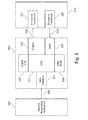
- Fig. 8 is a combined block and flow diagram illustrating operation of a device in accordance with an embodiment of the present invention.
- the device comprises a switch 850 for switching between an enrolment mode and a verification mode.
- the switch 850 is shown in a position corresponding to the enrolment mode.
- a particular challenge pattern is generated at step S80.
- the generated challenge pattern is stored in a secure part 860 of the memory unit 532 and forwarded to the transducers 521 and 522 for stimulating the piece 510 in accordance with the generated challenge pattern.
- step S81 the transmitting transducer 521 applies the stimulation to the piece 510 (also denoted "physical unclonable function device (PUFD)) in step S81, the piece 510 responds in step S82, and the receiving transducer 522 receives the response in step S83 and forwards it for pre-processing by the CPU 531 in step S84.
- step S85 the CPU 531 analyses the pre-processed response and extracts a number of characteristic features.
- step S86 the CPU 531 generates a template based on the extracted features. The generated template is stored in the secure part 860 of the memory unit 532.
- each challenge pattern may be applied using several different frequencies for the ultrasonic stimulation, such as 20 kHz, 40 kHz, 80 kHz, 160 kHz, 320 kHz, etc.
- the secure part 860 of the memory unit 532 contains at least one reference template for each challenge pattern.
- the steps S80 to S86 are performed in a similar way as in the enrolment mode described above.
- the verification mode differs from the enrolment mode in that the challenge at step S80 is generated in response to a received request for verification.
- the selected challenge pattern is marked in the secure part 860 of the memory unit 532 and the steps S81 to S86 are performed as described above.
- the template generated at step S86 is input to a template matching step which also receives the marked reference template from the secure part 860 of the memory unit 532.
- the verification ends at step S88 with either an "OK" or a "not OK".
Landscapes
- Engineering & Computer Science (AREA)
- Physics & Mathematics (AREA)
- General Physics & Mathematics (AREA)
- Health & Medical Sciences (AREA)
- Chemical & Material Sciences (AREA)
- Theoretical Computer Science (AREA)
- Computer Hardware Design (AREA)
- Immunology (AREA)
- Life Sciences & Earth Sciences (AREA)
- Biochemistry (AREA)
- Analytical Chemistry (AREA)
- Pathology (AREA)
- General Health & Medical Sciences (AREA)
- General Engineering & Computer Science (AREA)
- Computer Security & Cryptography (AREA)
- Software Systems (AREA)
- Mathematical Physics (AREA)
- Electrochemistry (AREA)
- Chemical Kinetics & Catalysis (AREA)
- Nuclear Medicine, Radiotherapy & Molecular Imaging (AREA)
- Management, Administration, Business Operations System, And Electronic Commerce (AREA)
- Investigating Or Analyzing Materials By The Use Of Ultrasonic Waves (AREA)
Priority Applications (1)
| Application Number | Priority Date | Filing Date | Title |
|---|---|---|---|
| EP14175992.8A EP2950232A1 (de) | 2014-05-30 | 2014-07-07 | Identifizierung von Anlagen |
Applications Claiming Priority (2)
| Application Number | Priority Date | Filing Date | Title |
|---|---|---|---|
| EP14170629 | 2014-05-30 | ||
| EP14175992.8A EP2950232A1 (de) | 2014-05-30 | 2014-07-07 | Identifizierung von Anlagen |
Publications (1)
| Publication Number | Publication Date |
|---|---|
| EP2950232A1 true EP2950232A1 (de) | 2015-12-02 |
Family
ID=50972448
Family Applications (1)
| Application Number | Title | Priority Date | Filing Date |
|---|---|---|---|
| EP14175992.8A Withdrawn EP2950232A1 (de) | 2014-05-30 | 2014-07-07 | Identifizierung von Anlagen |
Country Status (3)
| Country | Link |
|---|---|
| US (1) | US9772283B2 (de) |
| EP (1) | EP2950232A1 (de) |
| CN (1) | CN105278944B (de) |
Families Citing this family (5)
| Publication number | Priority date | Publication date | Assignee | Title |
|---|---|---|---|---|
| CN106442734B (zh) * | 2016-09-29 | 2024-06-18 | 中国人民解放军92228部队 | 一种小型不规则铸件声谱无损检测装置及检测方法 |
| WO2018162938A1 (en) * | 2017-03-10 | 2018-09-13 | Fraunhofer-Gesellschaft Zur Forderung Der Angewandten Forschung E.V. | Methods and system for labeling and detecting a clone-resistant physical unit |
| US10706139B2 (en) * | 2017-04-05 | 2020-07-07 | General Electric Company | System and method for authenticating components |
| CN108875419B (zh) * | 2017-05-15 | 2021-06-22 | 厦门雅迅网络股份有限公司 | 基于mems传感器生成终端唯一性标识的方法 |
| EP3886009A1 (de) * | 2020-03-27 | 2021-09-29 | Siemens Aktiengesellschaft | System und verfahren zur verwaltung einer anlage |
Citations (1)
| Publication number | Priority date | Publication date | Assignee | Title |
|---|---|---|---|---|
| WO2012122994A1 (en) * | 2011-03-11 | 2012-09-20 | Kreft Heinz | Off-line transfer of electronic tokens between peer-devices |
Family Cites Families (4)
| Publication number | Priority date | Publication date | Assignee | Title |
|---|---|---|---|---|
| US5969260A (en) * | 1998-03-30 | 1999-10-19 | Mcdonnell Douglas Corporation | Remotely interrogatable apparatus and method for detecting defects in structural members |
| US6793127B2 (en) * | 2001-04-04 | 2004-09-21 | Koninklijke Philips Electronics N.V. | Internet enabled resource constrained terminal for processing tags |
| FR2941782B1 (fr) * | 2009-01-30 | 2011-02-18 | Centre Nat Rech Scient | Procede de localisation d'apparition d'un defaut dans un milieu par une onde. |
| CN103390348B (zh) * | 2012-05-10 | 2015-09-02 | 航天信息股份有限公司 | 机动车的稽查方法和设备 |
-
2014
- 2014-07-07 EP EP14175992.8A patent/EP2950232A1/de not_active Withdrawn
-
2015
- 2015-05-08 US US14/708,067 patent/US9772283B2/en active Active
- 2015-05-27 CN CN201510279246.1A patent/CN105278944B/zh active Active
Patent Citations (1)
| Publication number | Priority date | Publication date | Assignee | Title |
|---|---|---|---|---|
| WO2012122994A1 (en) * | 2011-03-11 | 2012-09-20 | Kreft Heinz | Off-line transfer of electronic tokens between peer-devices |
Also Published As
| Publication number | Publication date |
|---|---|
| US9772283B2 (en) | 2017-09-26 |
| US20150346094A1 (en) | 2015-12-03 |
| CN105278944B (zh) | 2019-04-16 |
| CN105278944A (zh) | 2016-01-27 |
Similar Documents
| Publication | Publication Date | Title |
|---|---|---|
| US9772283B2 (en) | Identification of assets | |
| CN109257342B (zh) | 区块链跨链的认证方法、系统、服务器及可读存储介质 | |
| US10880080B1 (en) | Cryptographic key generation from biometric data | |
| CN112041849B (zh) | 用于自动对象识别和认证的方法和系统 | |
| CN100583170C (zh) | 用于产品真实性测试的产品保护入口和方法 | |
| US8447991B2 (en) | Card authentication system | |
| Periaswamy et al. | Fingerprinting RFID tags | |
| KR102503897B1 (ko) | 스마트카드 및 스마트카드를 제어하기 위한 방법 | |
| CN102812472A (zh) | 认证处理方法以及装置 | |
| CN112270005B (zh) | 一种数据传输方法和系统 | |
| US20190035201A1 (en) | Method and apparatus for establishing trust in smart card readers | |
| CN109190362B (zh) | 安全通信方法及相关设备 | |
| CN107078909B (zh) | 用于登记随机安全特征的方法和认证系统 | |
| US11528152B2 (en) | Watermarking for electronic device tracking or verification | |
| DE102007026836A1 (de) | Verfahren und System zur Prüfung der Echtheit eines Produkts und Lesegerät | |
| CN101778102A (zh) | 一种传感器的安全认证方法、传感器及其认证系统 | |
| CN118368089B (zh) | 基于零知识证明的身份验证方法、装置、设备和存储介质 | |
| US20200019690A1 (en) | Biometric authentication system and biometric authentication method using frequency response characteristics of biometric signal | |
| JP6065284B2 (ja) | リーダ装置、それを搭載するデータ処理装置および真偽判定方法 | |
| US12406049B2 (en) | Device and method for autheniticating hardware and/or embedded software | |
| Habibi et al. | Practical attacks on a RFID authentication protocol conforming to EPC C-1 G-2 standard | |
| CN112132576B (zh) | 基于区块链通信的支付信息处理方法及区块链信息平台 | |
| Assumpção et al. | Sensors fingerprints using machine learning: a case study on dam monitoring systems | |
| CN110070365B (zh) | 基于区块链的商品存证方法和装置、电子设备 | |
| CN107680218B (zh) | 基于多生物特征识别与瞬时证照技术的安检方法及系统 |
Legal Events
| Date | Code | Title | Description |
|---|---|---|---|
| AK | Designated contracting states |
Kind code of ref document: A1 Designated state(s): AL AT BE BG CH CY CZ DE DK EE ES FI FR GB GR HR HU IE IS IT LI LT LU LV MC MK MT NL NO PL PT RO RS SE SI SK SM TR |
|
| AX | Request for extension of the european patent |
Extension state: BA ME |
|
| PUAI | Public reference made under article 153(3) epc to a published international application that has entered the european phase |
Free format text: ORIGINAL CODE: 0009012 |
|
| 17P | Request for examination filed |
Effective date: 20160602 |
|
| RBV | Designated contracting states (corrected) |
Designated state(s): AL AT BE BG CH CY CZ DE DK EE ES FI FR GB GR HR HU IE IS IT LI LT LU LV MC MK MT NL NO PL PT RO RS SE SI SK SM TR |
|
| 17Q | First examination report despatched |
Effective date: 20181004 |
|
| STAA | Information on the status of an ep patent application or granted ep patent |
Free format text: STATUS: THE APPLICATION IS DEEMED TO BE WITHDRAWN |
|
| 18D | Application deemed to be withdrawn |
Effective date: 20190416 |