EP2950708B1 - Bildgebungssystem mit hyperspektraler kamerageführter sonde - Google Patents
Bildgebungssystem mit hyperspektraler kamerageführter sonde Download PDFInfo
- Publication number
- EP2950708B1 EP2950708B1 EP14707449.6A EP14707449A EP2950708B1 EP 2950708 B1 EP2950708 B1 EP 2950708B1 EP 14707449 A EP14707449 A EP 14707449A EP 2950708 B1 EP2950708 B1 EP 2950708B1
- Authority
- EP
- European Patent Office
- Prior art keywords
- probe
- hyperspectral
- hyperspectral image
- target structure
- imaging system
- Prior art date
- Legal status (The legal status is an assumption and is not a legal conclusion. Google has not performed a legal analysis and makes no representation as to the accuracy of the status listed.)
- Active
Links
Images


Classifications
-
- A—HUMAN NECESSITIES
- A61—MEDICAL OR VETERINARY SCIENCE; HYGIENE
- A61B—DIAGNOSIS; SURGERY; IDENTIFICATION
- A61B5/00—Measuring for diagnostic purposes; Identification of persons
- A61B5/0059—Measuring for diagnostic purposes; Identification of persons using light, e.g. diagnosis by transillumination, diascopy, fluorescence
- A61B5/0077—Devices for viewing the surface of the body, e.g. camera, magnifying lens
-
- A—HUMAN NECESSITIES
- A61—MEDICAL OR VETERINARY SCIENCE; HYGIENE
- A61B—DIAGNOSIS; SURGERY; IDENTIFICATION
- A61B5/00—Measuring for diagnostic purposes; Identification of persons
- A61B5/0033—Features or image-related aspects of imaging apparatus, e.g. for MRI, optical tomography or impedance tomography apparatus; Arrangements of imaging apparatus in a room
- A61B5/0035—Features or image-related aspects of imaging apparatus, e.g. for MRI, optical tomography or impedance tomography apparatus; Arrangements of imaging apparatus in a room adapted for acquisition of images from more than one imaging mode, e.g. combining MRI and optical tomography
-
- A—HUMAN NECESSITIES
- A61—MEDICAL OR VETERINARY SCIENCE; HYGIENE
- A61B—DIAGNOSIS; SURGERY; IDENTIFICATION
- A61B5/00—Measuring for diagnostic purposes; Identification of persons
- A61B5/0059—Measuring for diagnostic purposes; Identification of persons using light, e.g. diagnosis by transillumination, diascopy, fluorescence
- A61B5/0062—Arrangements for scanning
- A61B5/0066—Optical coherence imaging
-
- A—HUMAN NECESSITIES
- A61—MEDICAL OR VETERINARY SCIENCE; HYGIENE
- A61B—DIAGNOSIS; SURGERY; IDENTIFICATION
- A61B5/00—Measuring for diagnostic purposes; Identification of persons
- A61B5/0059—Measuring for diagnostic purposes; Identification of persons using light, e.g. diagnosis by transillumination, diascopy, fluorescence
- A61B5/0062—Arrangements for scanning
- A61B5/0068—Confocal scanning
-
- A—HUMAN NECESSITIES
- A61—MEDICAL OR VETERINARY SCIENCE; HYGIENE
- A61B—DIAGNOSIS; SURGERY; IDENTIFICATION
- A61B5/00—Measuring for diagnostic purposes; Identification of persons
- A61B5/0059—Measuring for diagnostic purposes; Identification of persons using light, e.g. diagnosis by transillumination, diascopy, fluorescence
- A61B5/0071—Measuring for diagnostic purposes; Identification of persons using light, e.g. diagnosis by transillumination, diascopy, fluorescence by measuring fluorescence emission
-
- A—HUMAN NECESSITIES
- A61—MEDICAL OR VETERINARY SCIENCE; HYGIENE
- A61B—DIAGNOSIS; SURGERY; IDENTIFICATION
- A61B5/00—Measuring for diagnostic purposes; Identification of persons
- A61B5/0059—Measuring for diagnostic purposes; Identification of persons using light, e.g. diagnosis by transillumination, diascopy, fluorescence
- A61B5/0075—Measuring for diagnostic purposes; Identification of persons using light, e.g. diagnosis by transillumination, diascopy, fluorescence by spectroscopy, i.e. measuring spectra, e.g. Raman spectroscopy, infrared absorption spectroscopy
-
- A—HUMAN NECESSITIES
- A61—MEDICAL OR VETERINARY SCIENCE; HYGIENE
- A61B—DIAGNOSIS; SURGERY; IDENTIFICATION
- A61B5/00—Measuring for diagnostic purposes; Identification of persons
- A61B5/0059—Measuring for diagnostic purposes; Identification of persons using light, e.g. diagnosis by transillumination, diascopy, fluorescence
- A61B5/0082—Measuring for diagnostic purposes; Identification of persons using light, e.g. diagnosis by transillumination, diascopy, fluorescence adapted for particular medical purposes
- A61B5/0084—Measuring for diagnostic purposes; Identification of persons using light, e.g. diagnosis by transillumination, diascopy, fluorescence adapted for particular medical purposes for introduction into the body, e.g. by catheters
-
- A—HUMAN NECESSITIES
- A61—MEDICAL OR VETERINARY SCIENCE; HYGIENE
- A61B—DIAGNOSIS; SURGERY; IDENTIFICATION
- A61B5/00—Measuring for diagnostic purposes; Identification of persons
- A61B5/74—Details of notification to user or communication with user or patient; User input means
- A61B5/742—Details of notification to user or communication with user or patient; User input means using visual displays
-
- A—HUMAN NECESSITIES
- A61—MEDICAL OR VETERINARY SCIENCE; HYGIENE
- A61B—DIAGNOSIS; SURGERY; IDENTIFICATION
- A61B8/00—Diagnosis using ultrasonic, sonic or infrasonic waves
- A61B8/12—Diagnosis using ultrasonic, sonic or infrasonic waves in body cavities or body tracts, e.g. by using catheters
-
- G—PHYSICS
- G01—MEASURING; TESTING
- G01J—MEASUREMENT OF INTENSITY, VELOCITY, SPECTRAL CONTENT, POLARISATION, PHASE OR PULSE CHARACTERISTICS OF INFRARED, VISIBLE OR ULTRAVIOLET LIGHT; COLORIMETRY; RADIATION PYROMETRY
- G01J3/00—Spectrometry; Spectrophotometry; Monochromators; Measuring colours
- G01J3/02—Details
- G01J3/0205—Optical elements not provided otherwise, e.g. optical manifolds, diffusers, windows
- G01J3/0218—Optical elements not provided otherwise, e.g. optical manifolds, diffusers, windows using optical fibers
-
- G—PHYSICS
- G06—COMPUTING OR CALCULATING; COUNTING
- G06T—IMAGE DATA PROCESSING OR GENERATION, IN GENERAL
- G06T7/00—Image analysis
- G06T7/70—Determining position or orientation of objects or cameras
-
- A—HUMAN NECESSITIES
- A61—MEDICAL OR VETERINARY SCIENCE; HYGIENE
- A61B—DIAGNOSIS; SURGERY; IDENTIFICATION
- A61B2560/00—Constructional details of operational features of apparatus; Accessories for medical measuring apparatus
- A61B2560/02—Operational features
- A61B2560/0223—Operational features of calibration, e.g. protocols for calibrating sensors
-
- A—HUMAN NECESSITIES
- A61—MEDICAL OR VETERINARY SCIENCE; HYGIENE
- A61B—DIAGNOSIS; SURGERY; IDENTIFICATION
- A61B2576/00—Medical imaging apparatus involving image processing or analysis
-
- A—HUMAN NECESSITIES
- A61—MEDICAL OR VETERINARY SCIENCE; HYGIENE
- A61B—DIAGNOSIS; SURGERY; IDENTIFICATION
- A61B5/00—Measuring for diagnostic purposes; Identification of persons
- A61B5/145—Measuring characteristics of blood in vivo, e.g. gas concentration or pH-value ; Measuring characteristics of body fluids or tissues, e.g. interstitial fluid or cerebral tissue
- A61B5/1455—Measuring characteristics of blood in vivo, e.g. gas concentration or pH-value ; Measuring characteristics of body fluids or tissues, e.g. interstitial fluid or cerebral tissue using optical sensors, e.g. spectral photometrical oximeters
-
- G—PHYSICS
- G01—MEASURING; TESTING
- G01J—MEASUREMENT OF INTENSITY, VELOCITY, SPECTRAL CONTENT, POLARISATION, PHASE OR PULSE CHARACTERISTICS OF INFRARED, VISIBLE OR ULTRAVIOLET LIGHT; COLORIMETRY; RADIATION PYROMETRY
- G01J3/00—Spectrometry; Spectrophotometry; Monochromators; Measuring colours
- G01J3/28—Investigating the spectrum
- G01J3/2823—Imaging spectrometer
-
- G—PHYSICS
- G06—COMPUTING OR CALCULATING; COUNTING
- G06T—IMAGE DATA PROCESSING OR GENERATION, IN GENERAL
- G06T2207/00—Indexing scheme for image analysis or image enhancement
- G06T2207/10—Image acquisition modality
- G06T2207/10064—Fluorescence image
-
- G—PHYSICS
- G06—COMPUTING OR CALCULATING; COUNTING
- G06T—IMAGE DATA PROCESSING OR GENERATION, IN GENERAL
- G06T2207/00—Indexing scheme for image analysis or image enhancement
- G06T2207/30—Subject of image; Context of image processing
- G06T2207/30004—Biomedical image processing
- G06T2207/30096—Tumor; Lesion
Definitions
- the present invention relates to the field of medical devices or equipment. More specifically, the invention relates to a medical imaging system and a method for identifying a target structure in biological tissue, such as for effective tumor margin assessment.
- the problem is thus how to inspect the surface of a resected tumor tissue for positive margins in a time efficient and a robust way.
- US 2009/326383 A1 describes a hyperspectral image system for identifying a suspect region of a subject.
- An optional contact probe module is used to collect a signal of the suspect region for medical diagnosis.
- US 2007/024946 A1 describes a hyperspectral imaging system for providing information physiologic measurements that support early detection of shock and outcomes therefrom.
- the invention provides a medical imaging system arranged to identify a target structure in an associated biological tissue, the system comprising
- the hyperspectral image can be used to provide an image of a sufficiently large area very quickly, but with a rather limited spectral resolution, and thus a rather low specificity regarding identification of the target structure within the biological tissue.
- the hyperspectral image can be used to indentify suspicious areas, i.e. areas where it can be expected that there is a certain possibility that the target structure is present.
- the hyperspectral image can then be used by the operator, e.g. by means of a visual indication on a display, as a guide towards selecting which location(s) within the first surface area covered by the hyperspectral image to be measured by a probe selected such that it provides a higher specificity with respect to identification of the target structure.
- the probe provides better data for identifying the target structure, e.g. by providing a higher spectral resolution than the hyperspectral image, but at the price of a limited measurement area, e.g. in the form of point or point-like measurements.
- a limited measurement area e.g. in the form of point or point-like measurements.
- an improved image with enhanced contrast and/or sensitivity with respect to identify the target structure e.g. tumor tissue
- the real-time hyperspectral images processed with the calibrated algorithm can be used to provide very quick inspection of further target structures.
- the high speed of the hyperspectral camera is used to point out suspicious area to be examined with the more time consuming probe.
- even one single point-like probe measurement can be used to significantly improve the hyperspectral image towards increasing sensitivity to identify the target structure.
- the medical imaging system according to the invention can provide a robust and time efficient identification of positive margins after resection. This allows the system to be used during surgery and thus increases the chance of removing all tumor tissue during oncological surgery without the need to redo the surgery, if it turns out at a later examination that not all tumor tissue had been successfully removed.
- the type of probe and subsequent processing of the probe measurement data should preferably be selected towards providing a high sensitivity towards indentifying the specific target structure in question.
- the hyperspectral camera system can be used to make visible images and hyperspectral images of the surface of the tissue specimen, a contact probe or surface probe capable of measuring locally inside the tissue near the surface of the specimen.
- the hyperspectral images are analyzed for suspicious areas based on look-up-table data and capable of analyzing the probe for suspicious signatures.
- the probe is capable of producing a signal indicative whether the probed surface contains a positive margin, and the area to be inspected with the surface probe is indicated in the visible image based on the hyperspectral image analysis.
- signals from the surface probe, taken at a few locations are used to calibrate the 2D-image processing algorithms used for analyzing the hyperspectral images.
- the probe data may especially be acquired with a larger spectral range, with higher spectral resolution, and may also cover part of the tissue below the surface, hence allowing an accurate assessment of these tissue points.
- the idea is that these surface probe measurements needs to be done only a few times during an intervention (e.g. when the 2D-spectral image processing indicates a large reconstruction uncertainty), and that once this calibration with the surface probe data has been performed and the system is re-calibrated, the operator can use the real-time 2D results obtained from the hyperspectral images according to the invention.
- the signals of the surface probe measurements are annotated in the visible image and or hyperspectral image based on image analysis of the visible image to register the probe tip location with the specimen at the time of measurement.
- the imaging system can also be used to identify other target structure, e.g. the presence of blood vessels, nerve bundles and the like below the surface of biological tissue, e.g. during surgery.
- other target structure e.g. the presence of blood vessels, nerve bundles and the like below the surface of biological tissue, e.g. during surgery.
- the probe measurement is acquired with a higher spectral resolution than the hyperspectral image.
- the hyperspectral image may be acquired with overlapping spectral bands of a rather low spectral resolution, or the spectral bands can be non-overlapping and thus have spectral bands without any information.
- the probe may provide measurement data with a higher spectral resolution which thus allows a higher specificity with respect to identify the target structure within the biological tissue.
- the second surface area is selected to be located within the first surface area, and thus that the probe measurement is performed within the area covered by the hyperspectral image.
- the probe is an interventional device, it is to be understood that by “within the first surface area” is understood that the probe measurement is performed in a point or small area in the biological tissue below the surface of the first surface area.
- the system may be arranged to visually display the hyperspectral image after being processed with the hyperspectral processing algorithm together with a visual indication of the part which is.
- a visual indication of the part which is.
- special shading, coloring, highlighting, or encircling can be used to graphically indicate the part or parts which are identified as possibly containing the target structure.
- the system is preferably arranged to visually display the hyperspectral image after being processed with the calibrated hyperspectral processing algorithm.
- the operator e.g. a physician, can inspect the resulting hyperspectral image, which after processing by the calibrated algorithm is now enhanced with respect to better visualize the target structure.
- the processor may be arranged to analyze the probe measurement data according to a probe processing algorithm comprising comparing the probe measurement data with a look-up-table.
- the processor may be arranged to analyze the probe measurement data according to a probe processing algorithm comprising calculating a plurality of measurement parameters and translating the plurality of measurement parameters into physiological parameters indicative of the target structure.
- the processor may be arranged to calibrate the hyperspectral processing algorithm by refining a grouping of pixels in the hyperspectral image which are identified in the probe measurement data as belonging to the target structure. Such improved grouping of pixels in the hyperspectral image will provide an enhanced visualization of the target structure. E.g. the grouping of pixels assigned with the same color or brightness may be changed or tuned based on parameters extracted from the probe measurement data.
- the probe may comprise a surface probe, and/or an interventional device.
- the probe may comprise an optical probe, and/or an ultrasound probe.
- the selection of which probe to use depends on the type of biological tissue and the target structure to be identified therein.
- the optical probe may comprise one of: a diffuse reflectance spectroscopy probe, a diffuse optical tomography probe, a differential path length spectroscopy, a fluorescence probe, a Raman spectroscopy probe, a confocal reflectance probe, a confocal fluorescence probe, a two-photon fluorescence probe, an optical coherence tomography probe, and a scanning fiber microscope arranged to perform confocal imaging.
- the hyperspectral camera system is arranged to provide two-dimensional real-time images, thus allowing real-time navigation of the probe tip if the hyperspectral images are display on a monitor to the probe operator.
- the hyperspectral camera system may in general be based on one of: (1) a dedicated hyperspectral camera which, based on light from a broadband light source, has wavelength separation inside the camera, (2) a light source with tunable wavelength or tunable filter set and a normal camera, and (3) a broadband light source and a tunable filter in front of normal camera.
- the hyperspectral camera system comprises one of:
- the processor may be arranged to process the hyperspectral image according to an image processing algorithm in order to identify a tip of the probe in the hyperspectral image, so as to identify to which part of the hyperspectral image the probe measurement data corresponds.
- an image processing algorithm in order to identify a tip of the probe in the hyperspectral image, so as to identify to which part of the hyperspectral image the probe measurement data corresponds.
- the imaging system can be used for identification of different target structures, such as: tumor tissue, a nerve bundle, a blood vessel (artery or vein), lymph nodes, and oxygenation level of tissue.
- the processor is preferably controlled by a control algorithm which can be implemented as a software program arranged for execution on a suitable processor system or computer.
- the processor of the system may be implemented in a dedicated device, e.g. including a display to display the hyperspectral images, or the processor of the system may be implemented as a software program arranged to execution on a server or a general purpose computer.
- the size and shape of the interventional device and/or surface probe is understood to be selected for a given application.
- the invention provides a method for detecting a target structure in an associated biological tissue, the method comprising
- providing hyperspectral image and “providing” probe measurement data covers a version of the method where “providing” means merely receiving data, e.g. in digital format, e.g. stored or transmitted data.
- providing covers actually taking the hyperspectral image of the biological tissue, and also performing the probe measurement on the biological tissue.
- the system according to the first aspect and the method according to the second aspect can be used in a number of applications, such as: identification of a positive margin after oncological surgery, identification of blood vessels (artery or vein) below a tissue surface, identification of a nerve bundle below a tissue surface, lymph nodes, and oxygenation level of tissue.
- FIG. 1 illustrates basic parts of a system embodiment with a hyperspectral camera HSC real-time 2D hyperspectral images HSI which are applied to a processor P and processed in a hyperspectral processing algorithm HSA.
- the hyperspectral camera HSC provides a hyperspectral image of a first area A1 of a biological tissue BT to be tested, e.g. a part of a human body to be tested with respect to the presence of a target structure in the form or tumor tissue TS.
- the hyperspectral image after processing I1 is then displayed in color or grey shadings on a display D, e.g. with a visual indicators graphically highlighting suspicious parts of the image which are identified as possible for containing tumor tissue TS.
- An optical surface probe PR provides probe measurement data PMD of a single measurement covering a second area A2 located within the first area A1 covered by the camera HSC.
- the probe measurement data PMD are applied to the processor and processed by a probe measurement algorithm PMA.
- This algorithm PMA may include extracting one or more physiological parameters PP based on the probe measurement data PMD.
- the probe is selected such that it provides measurement data PMD with a higher specificity with respect to identifying the tumor tissue TS, e.g. by providing a higher spectral resolution than the hyperspectral camera HSC.
- the probe PR covers a limited area A2, e.g.
- probe measurement data PMD including information that allows identification of the tumor tissue TS with a higher certainty than possible based on the hyperspectral image, e.g. due to a measurement technique allowing information further below the tissue surface than it is possible with a hyperspectral image.
- the physiological parameters PP extracted from the probe measurement data PMD are used to calibrate the hyperspectral processing algorithm HSA, e.g. by refining the grouping of image pixels in the hyperspectral image in order to better visually enhance physiological structures of the tumor tissue in the hyperspectral image.
- the hyperspectral image allows identification of parts of the area A1 covered where there is a possibility that tumor tissue is present, and this can be used as a guide for an operator towards selecting the point or area A2 to perform probe measurements, thus saving time consuming probe measurements covering the whole area A1.
- probes PR providing point measurements can be used which allow a very high specificity with respect to identification of tumor tissue TS, thus providing a highly reliable identification of tumor tissue TS within the first area A1 at a high speed.
- the probe can be a surface probe or an interventional device.
- optical fibers of the probe are preferably connected to an optical console.
- the optical detector can resolve light with a wavelength substantially in the visible and infrared regions of the wavelength spectrum, such as from 400 nm to 1700 nm and it may allow for diffuse reflectance measurements in both the visible and the near infrared wavelength range.
- DRS diffuse reflectance spectrum
- the information regarding the progress and whether the area under A1 under test contains tumor tissue can be provided in several ways by the processor P to the operator, e.g. a physician.
- a light indicator or an indication on the display D can be used that when showing a red light still tumor tissue is detected and with green light no tumor and/or optionally with yellow light suspects tumor.
- Another way is using an audible sound signal.
- Yet another way of informing the operator of the result is to calculate a probability of tumor detection by means of a graphical indication on the display D, such as a bar and/or with numbers and/or colors.
- the hyperspectral camera HSC provides real-time images, it is possible to visually indicate the presence of the probe in the displayed image, thus allowing the operator to place the probe in the suspicious area and perform the probe measurements therein.
- the processor may then include an image processing algorithm allowing a detection of the probe tip, so as to automatically assign the probe measurement data PMD to the correct location within the hyperspectral image.
- hyperspectral imaging a 2D-image of a distant object is taken, whereby for each pixel of the 2D-image the spectral content of the registered photons is being analyzed. This effectively results in a 3D-data set where the image intensity is stored as function of (X,Y)-coordinate and wavelength.
- MHSI Medical Hyperspectral Imaging
- reflected light can be collected at multiple wavelengths and processed to separate the oxy- and deoxyhemoglobin signals, and dedicated algorithms can be used to display data in an oxygenation map of tissue viability HyperMed Inc. "OxyVu Hyperspectral Imaging Technology.” from www.hypermed-inc.com.
- hyperspectral imaging systems with dedicated algorithms for identifying areas with indications for the presence of tumor tissue have been introduced [ Panasyuk, S. V., S. Yang, et al. (2007).
- the sensitivity is often hampered by the presence of extravagating blood on the tissue surface, which commonly occurs in open surgery.
- the limited wavelength range and spectral resolution also limit the specificity, since the major distinguishing parameters are blood content and blood oxygenation, and tumor discriminators which are less prominent in the visible wavelength range (such as tissue scattering and absorption by bile, water, fat, and others) may not be properly considered.
- the hyperspectral camera system can be arranged to obtain high spectral images using line scanning images, see e.g. [ K. Hamada, K. Fujita, N.I. Smith, M. Kobayashi, and S. Kawata, "Raman microscopy for dynamic molecular imaging", J Biomed Optics. 13(4), 044027 (1-4) (2008 )].
- line scanning images see e.g. [ K. Hamada, K. Fujita, N.I. Smith, M. Kobayashi, and S. Kawata, "Raman microscopy for dynamic molecular imaging", J Biomed Optics. 13(4), 044027 (1-4) (2008 )].
- the sample is illuminated using a white light source and the scattered/reflected photons after absorption is detected from the slit in front of the detector/camera.
- One direction the detector is used to capture the spectral information and the other direction is used to capture the lateral information along the line.
- the processor P may be implemented in various ways.
- the processor P may be integrated in a dedicated device including front-ends for the hyperspectral camera HSC and the probe PR.
- the processor P may be distributed to one or more separate computer (s) or processor system(s) remotely located from the camera HSC and probe PR.
- FIG. 2 illustrates a tip of a possible optical contact probe for point-based probe measurements.
- a source fiber end SF emits light, and a detector fiber end DF detects the reflected light.
- the tip could be the tip of the PR shown in FIG. 1 .
- the two fibers end SF, DF are arranged with a centre-to-centre distance of FD. This can be used e.g. for DRS, Fluorescence or Raman spectroscopy.
- DRS measurements with a contact probe can be executed very fast over a continuous wavelength range, and the probed volume can extend up to several millimeters into the tissue depending on the effective source-to-detector fiber(s) distance FD (e.g.
- single point DRS provides an enhanced sensitivity and specificity compared to hyperspectral imaging by measuring over a wavelength range extending into the NIR (e.g. from 400nm to 1600nm), which can include major contributions from additional tumor discriminators.
- a wavelength range extending into the NIR e.g. from 400nm to 1600nm
- additional tumor discriminators e.g. from 400nm to 1600nm
- R. Nachabe, D. Evers, BHW Hendriks, GW Lucassen, M. Van der Voort, EJ Rutgers, M-J Vrancken Peeters, JA van der Hage, HS Olderburg, J. Wesseling and TJM Ruers "Diagnosis of breast cancer using optical spectroscopy from 500 to 1600 nm: a comparison of classification methods, J. Biomed. Opt. 16 (2011) p087010 .].
- FIG. 3 illustrates a hyperspectral camera system based on a normal digital camera CM which provides 2D images of the biological tissue BT in a sequential manner controlled by a controller, where light sources L1, L2, and L3 sequentially applies their different narrow band light to the surface of the biological tissue BT.
- light sources L1, L2, and L3 sequentially applies their different narrow band light to the surface of the biological tissue BT.
- CM normal digital camera
- L1, L2 and L3 sequentially applies their different narrow band light to the surface of the biological tissue BT.
- biological tissue BT is located in a dark place during the sequential illumination by light sources L1-L3 to avoid any interference from other light sources.
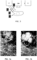
- FIGs. 4a and 4b show a constructed illustration of the same hyperspectral image before ( FIG. 4a ) and after ( FIG 4b ) calibration of the hyperspectral processing algorithm.
- suspicious areas which cannot be unambiguously classified by the hyperspectral image processing can be visually indicated to an operator, here illustrated as two areas indicated by dashed white lines. This is a guide to the operator to perform probe measurements within these suspicious areas, e.g. using a point measurement probe.
- the increased sensitivity and specificity of such point measurements for (residual) tumor discrimination can be used to recalibrate the hyperspectral processing image, e.g.
- FIG. 4b where the upper area in FIG 4a is seen to actually hide a tumor (white shading) which is clearly indicated in FIG. 4b , whereas the lower are indicated as suspicious in FIG 4a is seen in the enhanced image of FIG. 4b not to include tumor tissue.
- the point probe can also be used with fluorescence spectroscopy, which allows for enhanced tumor discrimination, e.g. by providing further information on the local metabolism, such as NAD+/NADH ratio, or the presence of autofluorescent tumor-specific markers in the tissue, such as cytostatic drugs like doxorubicin or paclitaxel.
- fluorescence spectroscopy chemical constituents associated with the presence of tumor cells can be identified with a very high accuracy and can give complement information for the recalibration of the hyperspectral processing algorithm.
- FIGs. 5a-5c show examples of different strategies for probe measurements with point or at least small area measurements serving to cover a larger area.
- FIG. 5a shows point measurements
- FIGs. 5b and 5c show clusters of points covering a region of interest.
- the strategy shown in FIGs. 5b and 5c can be obtained using a combination of a single point probe and a scanning fiber microscope.
- the probe may comprise both a single point probe and a scanning fiber microscope [ BHW Hendriks, WCJ Bierhoff, JJL Horikx, AE Desjardins, CA Hezemans, GW 't Hooft, GW Lucassen, and N Mihajlovic, "High-resolution resonant and non resonant fiber-scanning confocal microscope", J. Biomed. Opt. 16 (2011) p026007 ].
- Such scanning fiber microscope enables confocal imaging of the biological tissue under examination with a significant spatial resolution, field of view (FOV), and contrast.
- the combination in addition to the hyperspectral image provides a significant advancement over a single point measurement, e.g. as FIG. 5a .
- This modality enables multi-spectral imaging, full wavelength regions, over a spatial region of interest ( ⁇ 200 ⁇ m) with a submicron resolution ( ⁇ 0.6 ⁇ m).
- the modality can be used to obtain full spectral information either from a single region of interest, such as shown in FIG. 5b , or in combination as shown in FIG. 5c to cover many individual regions of interested, thus allowing information of a significantly larger region.
- the combination probe system could further employ different optical imaging modalities to be readily implemented such as confocal reflectance [ K. Carlson, M. Chidley, K-B. Sung, M. Descour, A. Gillenwater, M. Follen, and R. Richards-Kortum, "In vivo fiber-optic confocal reflectance microscope with an injection-molded plastic miniature objective lens," Appl. Opt. 44(10), 1792-1797 (2005 )], confocal fluorescence [ J. C. Jung, A. D. Mehta, E. Aksay, R. Stepnoski, and M. J. Schnitzer, "In vivo mammalian brain imaging using one- and two-photon fluorescence microendoscopy," J.
- confocal reflectance K. Carlson, M. Chidley, K-B. Sung, M. Descour, A. Gillenwater, M. Follen, and R. Richards-Kortum, "In vivo fiber-opti
- FIG. 6 illustrates a diagnostic embodiment where, referring to FIG. 1 , the hyperspectral image 12 after calibration of the hyperspectral image algorithm HSA is applied to the display D.
- a diagnosis algorithm DA processes the same image 12 and detects therein the area where the target structure is probable to be, e.g. a tumor.
- a target indicator TI is then applied to the display, e.g. a highlighting in the form of a color, a shading, a line around the area or the like.
- Wilson "A diffusion theory model of spatially resolved, steady-state diffuse reflectance for the non-invasive determination of tissue optical properties," Med. Phys. 19 (1992) p. 879-888 ] are the absorption coefficient ⁇ a ( ⁇ ), the reduced scattering coefficient ⁇ ' a ( ⁇ ) and the center-to-center distance between the emitting and collecting fibers at the tip of the probe. For the camera image there is no fiber distance and the model of Farrel is no longer applicable. Instead it is possible to use algorithms based on the well-known Kubelka-Munk model. An example of how reflectivity is derived from scattering and absorption properties is given e.g. in [ M. Müller, G. F. Zhou " Modeling electrophoretic paper-like displays", Proc.
- the parameter ⁇ corresponds to the reduced scattering amplitude at this specific wavelength.
- ⁇ s ⁇ ⁇ ⁇ MR ⁇ ⁇ 0 ⁇ b + 1 ⁇ ⁇ MR ⁇ ⁇ 0 ⁇ 4 c m ⁇ 1
- the reduced scattering coefficient is expressed as the sum of Mie and Rayleigh scattering where ⁇ MR is the Mie-to-total reduced scattering fraction.
- the reduced scattering slope of the Mie scattering is denoted b and is related to the particle size.
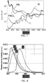
- FIG. 7 shows logarithmic plots of absorption spectra for blot Hb, Hb0 2 , water W, and fat F.
- ⁇ a Tissue ⁇ C ⁇ v Blood ⁇ a Blood ⁇ + v WL ⁇ a WL ⁇ c m ⁇ 1 , where ⁇ a Blood ⁇ corresponds to the absorption by blood and ⁇ a WL ⁇ corresponds to absorption by water and lipid together in the probed volume.
- the factor C is a wavelength dependent correction factor that accounts for the effect of pigment packaging and alters for the shape of the absorption spectrum. This effect can be explained by the fact that blood in tissue is confined to a very small fraction of the overall volume, namely blood vessels. Red blood cells near the center of the vessel therefore absorb less light than those at the periphery. Effectively, when distributed homogeneously within the tissue, fewer red blood cells would produce the same absorption as the actual number of red blood cells distributed in discrete vessels.
- ⁇ a WL ⁇ ⁇ WL ⁇ a Lipid ⁇ + 1 ⁇ ⁇ WL ⁇ a H 2 O ⁇ c m ⁇ 1
- ⁇ WF [ Lipid ]/([ Lipid ]+[ H 2 O ]), where [ Lipid ] and [ H 2 O ], correspond to the concentration of lipid (density of 0.86g/ml) and water, respectively.
- Another way to discriminate differences in spectra is by making use of a principal components analysis. This method allows classification of differences in spectra and thus allows discrimination between tissues. It is also possible to extract features from the spectra.
- FIG. 8 shows intrinsic fluorescence curves for A: Collagen, B: Elastin, C: NADH, and D: FAD. Such parameters could also be measured with a probe. Especially, the ratio NADH/FAD, which is called the optical redox parameter, could be calculated, since this ratio is an indicator for the metabolic state of the tissue, which is assumed to change upon effective treatment of cancer cells, see e.g. [ Q. Zhang, M.G. Mueller, J. Wu and M.S. Feld, "Turbidity-free fluorescence spectroscopy of biological tissue” Opt. Lett. 25 (2000) p1451 ].
- FIG. 9 illustrates a method embodiment according to the invention for identifying possible tumor tissue within a human or animal tissue.
- the method comprises the step R_HSI of receiving a hyperspectral image of a first area of the tissue under test, optionally also the step of providing the hyperspectral image with a hyperspectral camera.
- the hyperspectral image is then analyzed L_TT with an algorithm for identifying and/or localizing a part or parts of the hyperspectral image which may contain tumor tissue.
- the next step D_SA is displaying the hyperspectral image with indication of the suspicious areas, e.g. using a line or other graphical symbol overlaid the hyperspectral image.
- the hyperspectral image is processed with an initial setting or calibration of a hyperspectral image algorithm, e.g. a setting selected based on the target structure, in this case tumor tissue, to be identified.
- a hyperspectral image algorithm e.g. a setting selected based on the target structure, in this case tumor tissue, to be identified.
- the operator then has a visual indication of which parts of the tissue under test to perform probe measurements.
- the next step R PMD is receiving probe measurement data, optionally also the step of providing the probe measurements resulting in the probe measurement data.
- the probe measurement data are obtained with an optical surface probe providing measurement data in a second area being essentially in one point within the first area, preferably within the suspicious area indentified and displayed.
- the probe measurement data is then analyzed A PMD with an algorithm arranged to identify one or more physiological parameters, e.g. based on a measured optical absorption coefficient, the reduced scattering coefficient and the center-to-center distance between light emitting and collecting fibers at the tip of the probe.
- the result is then used for calibrating C_HSA the processing algorithm used to analyze the hyperspectral image, so as to adapt the processing algorithm to provide an image with an enhanced contrast between target structure, in this example tumor tissue, and the tissue under test.
- the hyperspectral image is analyzed A HSI using the calibrated hyperspectral image processing algorithm.
- the re-analyzed hyperspectral image is displayed D HSI, e.g. on a color monitor.
- one or a few point measurements with a high spectral resolution can be utilized to add information about the tissue in suspicious areas of the standard-processed hyperspectral image so as to modify the hyperspectral processing algorithm.
- This is then used to process the hyperspectral image in order to provide an image with enhanced contrast or sensitivity towards distinguishing between the tissue under test and the target structure, e.g. tumor tissue.
- the method assists the operator, e.g. a medical doctor or other medical staff, in evaluating whether tumor tissue is present within an area under test, e.g. in the search for positive margins.
- the method may include indicating suspicious areas also in the re-analyzed hyperspectral image, and/or indicating the probability of tumor tissue being present.
- the invention provides a medical imaging system for identifying a target structure, e.g. a tumor, in a biological tissue.
- a hyperspectral camera system is used for imaging a surface area of the tissue, e.g. with a limited spectral resolution, but enough to allow identification of suspicious areas where the target structure may be, e.g. such areas can be visually indicated on a display to the operator.
- a probe e.g. an optical surface probe, is used to provide probe measurement of a smaller surface area of the tissue, but with more information indicative of the target structure. The probe is selected to provide a higher specificity with respect to identification of the target structure than the hyperspectral camera.
- the hyperspectral processing algorithm is then calibrated based on probe measurement data performed within the suspicious areas, thus providing a calibrated hyperspectral processing algorithm resulting in images with an enhanced sensitivity to identify the target structure. Only few probe measurements are required to significantly improve the resulting image, thereby providing a reliable and fast target structure identification.
- a computer program may be stored/distributed on a suitable medium, such as an optical storage medium or a solid-state medium supplied together with or as part of other hardware, but may also be distributed in other forms, such as via the Internet or other wired or wireless telecommunication systems. Any reference signs in the claims should not be construed as limiting the scope.
Landscapes
- Health & Medical Sciences (AREA)
- Life Sciences & Earth Sciences (AREA)
- Physics & Mathematics (AREA)
- Engineering & Computer Science (AREA)
- General Health & Medical Sciences (AREA)
- Biomedical Technology (AREA)
- Heart & Thoracic Surgery (AREA)
- Medical Informatics (AREA)
- Molecular Biology (AREA)
- Surgery (AREA)
- Animal Behavior & Ethology (AREA)
- Biophysics (AREA)
- Public Health (AREA)
- Veterinary Medicine (AREA)
- Pathology (AREA)
- Spectroscopy & Molecular Physics (AREA)
- Nuclear Medicine, Radiotherapy & Molecular Imaging (AREA)
- Radiology & Medical Imaging (AREA)
- General Physics & Mathematics (AREA)
- Theoretical Computer Science (AREA)
- Computer Vision & Pattern Recognition (AREA)
- Investigating Or Analysing Materials By Optical Means (AREA)
- Measurement Of The Respiration, Hearing Ability, Form, And Blood Characteristics Of Living Organisms (AREA)
- Endoscopes (AREA)
- Investigating, Analyzing Materials By Fluorescence Or Luminescence (AREA)
- Measuring And Recording Apparatus For Diagnosis (AREA)
Claims (15)
- Medizinisches Bildgebungssystem, das dafür eingerichtet ist, eine Zielstruktur in einem zugehörigen biologischen Gewebe (BT) zu identifizieren, wobei das System Folgendes umfasst:- ein hyperspektrales Kamerasystem (HSC), das dafür eingerichtet ist, ein hyperspektrales Bild (HIS) bereitzustellen, und dafür konfiguriert ist, einen ersten Oberflächenbereich (A1) des biologischen Gewebes (BT) abzudecken, wobei Pixel des hyperspektralen Bilds (HIS) Informationen bei verschiedenen Lichtwellenlängenbändern enthalten,- eine Sonde (PR), die dafür eingerichtet ist, eine Sondenmessung eines zweiten Oberflächenbereichs (A2) des biologischen Gewebes (BT) mit Informationen, die eine Zielstruktur (TS) angeben, bereitzustellen, und entsprechend Sondenmessdaten (PMD) zu erzeugen, wobei die Sonde (PR) derartig konfiguriert ist, dass der abgedeckte zweite Oberflächenbereich (A2) kleiner ist als der erste Oberflächenbereich (A1), der durch das hyperspektrale Kamerasystem (HSC) abgedeckt wird, und wobei die Sonde (PR) ausgewählt ist, um eine höhere Spezifizität in Bezug auf die Identifizierung der Zielstruktur (TS) bereitzustellen als das hyperspektrale Kamerasystem (HSC), und- einen Prozessor (P), der funktional verbunden ist, um das hyperspektrale Bild (HSI) und die Sondenmessdaten (PMD) zu empfangen, wobei der Prozessor (P) dafür eingerichtet ist, das hyperspektrale Bild (HIS) gemäß einem hyperspektralen Verarbeitungsalgorithmus (HSA) zu analysieren, um einen Teil des hyperspektralen Bilds (HSI) zu identifizieren, der möglicherweise die Zielstruktur (TS) enthält,dadurch gekennzeichnet, dass der Prozessor (P) ferner dafür eingerichtet ist, die Sondenmessdaten (PMD) zu analysieren und den hyperspektralen Verarbeitungsalgorithmus (HSA) als Reaktion darauf zu kalibrieren, um so einen kalibrierten hyperspektralen Verarbeitungsalgorithmus (HSA) mit einer verbesserten Empfindlichkeit zum Identifizieren der Zielstruktur (TS) in dem hyperspektralen Bild (HSI) bereitzustellen.
- Medizinisches Bildgebungssystem nach Anspruch 1, wobei die Sondenmessung mit einer höheren spektralen Auflösung als das hyperspektrale Bild (HSI) erfasst wird.
- Medizinisches Bildgebungssystem nach Anspruch 1, wobei der zweite Oberflächenbereich (A2) so ausgewählt ist, dass er sich innerhalb des ersten Oberflächenbereichs (A1) befindet.
- Medizinisches Bildgebungssystem nach Anspruch 1, wobei das System dafür eingerichtet ist, das hyperspektrale Bild (I1) nach der Verarbeitung mit dem hyperspektralen Verarbeitungsalgorithmus (HSA) zusammen mit einer visuellen Angabe des Teils, der als möglicherweise die Zielstruktur (TS) enthaltend identifiziert wurde, visuell anzuzeigen.
- Medizinisches Bildgebungssystem nach Anspruch 1, wobei das System dafür eingerichtet ist, das hyperspektrale Bild (I2) nach der Verarbeitung mit dem kalibrierten hyperspektralen Verarbeitungsalgorithmus (HSA) visuell anzuzeigen.
- Medizinisches Bildgebungssystem nach Anspruch 1, wobei der Prozessor (P) dafür eingerichtet ist, die Sondenmessdaten (PMD) gemäß einem Sondenverarbeitungsalgorithmus (PMA) zu analysieren, der das Vergleichen der Sondenmessdaten (PMD) mit einer Nachschlagetabelle umfasst.
- Medizinisches Bildgebungssystem nach Anspruch 1, wobei der Prozessor (P) dafür eingerichtet ist, die Sondenmessdaten (PMD) gemäß einem Sondenverarbeitungsalgorithmus (PMA) zu analysieren, der das Berechnen einer Vielzahl von Messparametern und das Übersetzen der Vielzahl von Messparametern in physiologische Parameter (PP) umfasst, welche die Zielstruktur (TS) angeben.
- Medizinisches Bildgebungssystem nach Anspruch 1, wobei der Prozessor (P) dafür eingerichtet ist, den hyperspektralen Verarbeitungsalgorithmus (HSA) zu kalibrieren, indem eine Gruppierung von Pixeln in dem hyperspektralen Bild (HSI) verfeinert wird, die in den Sondenmessdaten (PMD) als zu der Zielstruktur (TS) gehörend identifiziert wurden.
- Medizinisches Bildgebungssystem nach Anspruch 1, wobei die Sonde (PR) eines von Folgendem umfasst: eine Oberflächensonde oder eine interventionelle Vorrichtung.
- Medizinisches Bildgebungssystem nach Anspruch 1, wobei die Sonde (PR) eines von Folgendem umfasst: eine optische Sonde oder eine Ultraschallsonde.
- Medizinisches Bildgebungssystem nach Anspruch 1, wobei die Sonde (PR) eines von Folgendem umfasst: eine diffuse Reflexionsspektroskopiesonde, eine diffuse optische Tomographiesonde, eine differentielle Pfadlängenspektroskopie, eine Fluoreszenzsonde, eine Raman-Spektroskopiesonde, eine konfokale Reflexionssonde, eine konfokale Fluoreszenzsonde, eine Zwei-Photonen-Fluoreszenzsonde, eine optische Kohärenztomographiesonde oder ein Rasterfasermikroskop, dafür vorgesehen, konfokale Bildgebung durchzuführen.
- Medizinisches Bildgebungssystem nach Anspruch 1, wobei das hyperspektrale Kamerasystem eines von Folgendem umfasst:- eine hyperspektrale Kamera (HSC), die dafür eingerichtet ist, das hyperspektrale Bild (HSI) bereitzustellen,- eine normale Kamera (CM) und eine Vielzahl von Lichtquellen (L1, L2, L3) mit verschiedenen Schmalbandwellenlängen und eine Steuereinheit (C), die dafür eingerichtet ist, Bilder mit dem biologischen Gewebe (BT) bereitzustellen, die sequentiell durch die Vielzahl von Lichtquellen (L1, L2, L3) beleuchtet werden, und- eine normale Kamera und einen abstimmbaren optischen Filter, der zwischen der normalen Kamera und dem biologischen Gewebe angeordnet ist, um sequentielle Bilder mit unterschiedlichen Einstellungen des abstimmbaren optischen Filters bereitzustellen.
- Medizinisches Bildgebungssystem nach Anspruch 1, wobei der Prozessor (P) dafür eingerichtet ist, das hyperspektrale Bild (HSI) gemäß einem Bildverarbeitungsalgorithmus zu verarbeiten, um eine Spitze der Sonde (PR) in dem hyperspektralen Bild (HSI) zu identifizieren, um so zu identifizieren, welchem Teil des hyperspektralen Bilds (A2) die Sondenmessdaten (PMD) entsprechen.
- Medizinisches Bildgebungssystem nach Anspruch 1, wobei die Zielstruktur (TS) eines von Folgendem ist: Tumorgewebe, ein Nervenbündel, ein Blutgefäß, Lymphknoten oder Sauerstoffanreicherungsgrad von Gewebe.
- Verfahren zum Detektieren einer Zielstruktur in einem zugehörigen biologischen Gewebe, wobei das Verfahren Folgendes umfasst:- Bereitstellen (R HSI) eines hyperspektralen Bilds, um einen ersten Oberflächenbereich des zugehörigen biologischen Gewebes abzudecken, wobei Pixel des hyperspektralen Bilds Informationen in Bezug auf verschiedene Lichtwellenlängenbänder enthalten,- Bereitstellen (R_PMD) von Sondenmessdaten gemäß einer Sondenmessung, die konfiguriert ist, um einen zweiten Oberflächenbereich des biologischen Gewebes mit Informationen, die eine Zielstruktur angeben, abzudecken, wobei der zweite Oberflächenbereich kleiner ist als der erste Oberflächenbereich und sich innerhalb des ersten Oberflächenbereichs befindet, und wobei die Sondenmessung ausgewählt wird, um eine höhere Spezifizität in Bezug auf die Identifizierung der Zielstruktur bereitzustellen als das hyperspektrale Kamerasystem,- Analysieren (A HSI) des hyperspektralen Bilds gemäß einem hyperspektralen Verarbeitungsalgorithmus, um einen Teil des hyperspektralen Bilds zu identifizieren, der möglicherweise die Zielstruktur enthält,- Analysieren (A_PMD) der Sondenmessdaten, und
gekennzeichnet durch- Kalibrieren (C_HSA) des hyperspektralen Verarbeitungsalgorithmus als Reaktion auf ein Ergebnis der Analyse der Sondenmessdaten, um so einen kalibrierten hyperspektralen Verarbeitungsalgorithmus mit einer verbesserten Empfindlichkeit zum Identifizieren der Zielstruktur in dem hyperspektralen Bild (HSI) bereitzustellen.
Applications Claiming Priority (2)
| Application Number | Priority Date | Filing Date | Title |
|---|---|---|---|
| US201361758312P | 2013-01-30 | 2013-01-30 | |
| PCT/IB2014/058455 WO2014118674A2 (en) | 2013-01-30 | 2014-01-22 | Imaging system with hyperspectral camera guided probe |
Publications (2)
| Publication Number | Publication Date |
|---|---|
| EP2950708A2 EP2950708A2 (de) | 2015-12-09 |
| EP2950708B1 true EP2950708B1 (de) | 2019-01-16 |
Family
ID=50190503
Family Applications (1)
| Application Number | Title | Priority Date | Filing Date |
|---|---|---|---|
| EP14707449.6A Active EP2950708B1 (de) | 2013-01-30 | 2014-01-22 | Bildgebungssystem mit hyperspektraler kamerageführter sonde |
Country Status (5)
| Country | Link |
|---|---|
| US (1) | US11154199B2 (de) |
| EP (1) | EP2950708B1 (de) |
| JP (1) | JP6247316B2 (de) |
| CN (1) | CN104968257B (de) |
| WO (1) | WO2014118674A2 (de) |
Families Citing this family (33)
| Publication number | Priority date | Publication date | Assignee | Title |
|---|---|---|---|---|
| US10154826B2 (en) | 2013-07-17 | 2018-12-18 | Tissue Differentiation Intelligence, Llc | Device and method for identifying anatomical structures |
| US10716536B2 (en) | 2013-07-17 | 2020-07-21 | Tissue Differentiation Intelligence, Llc | Identifying anatomical structures |
| US10779713B2 (en) | 2014-12-09 | 2020-09-22 | Chemimage Corporation | Molecular chemical imaging endoscopic imaging systems |
| US11357405B2 (en) * | 2015-12-21 | 2022-06-14 | Erasmus University Medical Center Rotterdam | Optical probe for measuring a tissue sample |
| US9788770B1 (en) * | 2016-04-14 | 2017-10-17 | Verily Life Sciences Llc | Continuous monitoring of tumor hypoxia using near-infrared spectroscopy and tomography with a photonic mixer device |
| US11986341B1 (en) | 2016-05-26 | 2024-05-21 | Tissue Differentiation Intelligence, Llc | Methods for accessing spinal column using B-mode imaging to determine a trajectory without penetrating the the patient's anatomy |
| US11701086B1 (en) | 2016-06-21 | 2023-07-18 | Tissue Differentiation Intelligence, Llc | Methods and systems for improved nerve detection |
| ES2842850T3 (es) | 2016-11-22 | 2021-07-15 | Univ De Las Palmas De Gran Canaria | Procedimiento de detección no invasiva de tejido de tumor y/o tejido sano y aparato de imágenes hiper espectrales |
| US10806334B2 (en) * | 2017-02-28 | 2020-10-20 | Verily Life Sciences Llc | System and method for multiclass classification of images using a programmable light source |
| CN110869740A (zh) | 2017-07-19 | 2020-03-06 | 美国西门子医学诊断股份有限公司 | 使用高光谱成像的样本表征的方法和设备 |
| WO2019094341A1 (en) * | 2017-11-10 | 2019-05-16 | Clinicai, Inc. | System, composition and method for the detection of spectral biomarkers of a condition and patterns from stool samples |
| EP3787469A4 (de) * | 2018-04-30 | 2021-11-10 | ChemImage Corporation | Endoskopische bildgebungssysteme zur molekularen chemischen bildgebung |
| US11559298B2 (en) * | 2018-07-16 | 2023-01-24 | Cilag Gmbh International | Surgical visualization of multiple targets |
| EP3890584B1 (de) * | 2018-12-05 | 2024-07-31 | Intuitive Surgical Operations, Inc. | Bestimmung von chromophorkonzentrationen in geweben |
| US11826124B2 (en) | 2019-01-29 | 2023-11-28 | Board Of Regents, The University Of Texas System | Apparatus and method for image-guided interventions with hyperspectral imaging |
| US11869176B2 (en) * | 2019-01-31 | 2024-01-09 | University Of Southern California | Hyperspectral imaging system |
| JP6879520B2 (ja) * | 2019-08-28 | 2021-06-02 | サイバネットシステム株式会社 | 画像処理装置及び画像処理方法 |
| GB2589068A (en) * | 2019-10-31 | 2021-05-26 | Odi Medical As | Probe |
| US11776144B2 (en) * | 2019-12-30 | 2023-10-03 | Cilag Gmbh International | System and method for determining, adjusting, and managing resection margin about a subject tissue |
| DE102020102476B4 (de) * | 2020-01-31 | 2024-02-08 | Carl Zeiss Meditec Ag | Methode zum Kennzeichnen eines Bereiches eines Tumors |
| CN111281313A (zh) * | 2020-03-05 | 2020-06-16 | 中国科学院长春光学精密机械与物理研究所 | 基于拉曼光谱的病灶在线检测系统 |
| CA3266085A1 (en) * | 2020-03-18 | 2025-03-14 | Nutek O.I.D.O Ltd | SYSTEM AND METHOD FOR DETECTING RESIDUAL CANCER TISSUE |
| KR20230041661A (ko) * | 2020-06-02 | 2023-03-24 | 노아 메디컬 코퍼레이션 | 삼중 이미징 하이브리드 프로브를 위한 시스템들 및 방법들 |
| CN112213310A (zh) * | 2020-11-03 | 2021-01-12 | 广州大秦光镊科学仪器科技有限公司 | 一种高光谱成像显微大数据测量系统及方法 |
| CN116829926A (zh) * | 2020-12-03 | 2023-09-29 | 兹吾斯控股有限公司 | 基于高光谱成像检查医药物品 |
| WO2022120235A1 (en) * | 2020-12-03 | 2022-06-09 | Edda Technology, Inc. | Spectro-mechanical imaging for characterizing embedded lesions |
| JPWO2022176621A1 (de) * | 2021-02-19 | 2022-08-25 | ||
| KR102298680B1 (ko) | 2021-02-26 | 2021-09-07 | (주)메디띵스 | 협대역 확산 반사 분광법을 이용한 혼탁매질에서의 수분 및 지질 함량 정량화 방법 |
| CN113252585B (zh) * | 2021-04-21 | 2024-02-09 | 深圳市海谱纳米光学科技有限公司 | 一种基于高光谱图像判断黄金表面覆膜的方法和装置 |
| GB2606359A (en) * | 2021-05-04 | 2022-11-09 | Arspectra Sarl | Augmented reality headset and probe for medical imaging |
| US12033329B2 (en) * | 2021-07-22 | 2024-07-09 | X Development Llc | Sample segmentation |
| TWI831091B (zh) * | 2021-11-30 | 2024-02-01 | 財團法人金屬工業研究發展中心 | 高光譜影像的分析方法及系統 |
| CN116672000A (zh) * | 2023-05-30 | 2023-09-01 | 无锡海斯凯尔医学技术有限公司 | 组织定位的数据处理方法、装置、电子设备 |
Citations (1)
| Publication number | Priority date | Publication date | Assignee | Title |
|---|---|---|---|---|
| US20130003064A1 (en) * | 2011-01-03 | 2013-01-03 | National Institute Of Standards And Technology | Dynamic Spectral Radiance Calibration Source |
Family Cites Families (8)
| Publication number | Priority date | Publication date | Assignee | Title |
|---|---|---|---|---|
| US6810279B2 (en) | 2000-11-07 | 2004-10-26 | Hypermed, Inc. | Hyperspectral imaging calibration device |
| WO2006058306A2 (en) | 2004-11-29 | 2006-06-01 | Hypermed, Inc. | Medical hyperspectral imaging for evaluation of tissue and tumor |
| JP5149015B2 (ja) * | 2004-12-28 | 2013-02-20 | ハイパーメツド・イメージング・インコーポレイテツド | 全身生理機能およびショックの決定、評価および監視におけるハイパースペクトル/マルチスペクトルイメージング |
| US9117133B2 (en) * | 2008-06-18 | 2015-08-25 | Spectral Image, Inc. | Systems and methods for hyperspectral imaging |
| CN101455559B (zh) | 2008-12-15 | 2011-06-29 | 深圳先进技术研究院 | 一种人体红外高光谱成像方法和系统 |
| US9198640B2 (en) | 2009-05-06 | 2015-12-01 | Real Imaging Ltd. | System and methods for providing information related to a tissue region of a subject |
| CN101617935B (zh) | 2009-08-06 | 2011-05-04 | 浙江大学 | Oct中基于时空分光的宽光谱高分辨探测方法及系统 |
| CN101785663B (zh) | 2010-03-09 | 2011-07-20 | 华南师范大学 | 一种光声与x光检测双模态数字化成像系统及成像方法 |
-
2014
- 2014-01-22 US US14/653,554 patent/US11154199B2/en active Active
- 2014-01-22 JP JP2015554284A patent/JP6247316B2/ja not_active Expired - Fee Related
- 2014-01-22 EP EP14707449.6A patent/EP2950708B1/de active Active
- 2014-01-22 CN CN201480006485.3A patent/CN104968257B/zh not_active Expired - Fee Related
- 2014-01-22 WO PCT/IB2014/058455 patent/WO2014118674A2/en not_active Ceased
Patent Citations (1)
| Publication number | Priority date | Publication date | Assignee | Title |
|---|---|---|---|---|
| US20130003064A1 (en) * | 2011-01-03 | 2013-01-03 | National Institute Of Standards And Technology | Dynamic Spectral Radiance Calibration Source |
Also Published As
| Publication number | Publication date |
|---|---|
| WO2014118674A2 (en) | 2014-08-07 |
| US20160007858A1 (en) | 2016-01-14 |
| CN104968257B (zh) | 2018-04-10 |
| EP2950708A2 (de) | 2015-12-09 |
| WO2014118674A3 (en) | 2014-11-20 |
| JP2016511015A (ja) | 2016-04-14 |
| JP6247316B2 (ja) | 2017-12-13 |
| CN104968257A (zh) | 2015-10-07 |
| US11154199B2 (en) | 2021-10-26 |
Similar Documents
| Publication | Publication Date | Title |
|---|---|---|
| EP2950708B1 (de) | Bildgebungssystem mit hyperspektraler kamerageführter sonde | |
| US11656448B2 (en) | Method and apparatus for quantitative hyperspectral fluorescence and reflectance imaging for surgical guidance | |
| US12390112B2 (en) | Atherosclerotic plaque detection | |
| US11406367B2 (en) | System with photonic biopsy device for obtaining pathological information | |
| Kiyotoki et al. | New method for detection of gastric cancer by hyperspectral imaging: a pilot study | |
| CA2917308C (en) | Methods related to real-time cancer diagnostics at endoscopy utilizing fiber-optic raman spectroscopy | |
| US10299684B2 (en) | User interface for photonic tools and electromagnetic tracking guided bronchoscope | |
| JP6772066B2 (ja) | 画像を処理して解析するための検査装置 | |
| KR101492803B1 (ko) | 촉각 영상 및 근적외선 영상의 정합을 이용한 유방촬영용 영상진단기기 및 유방조직 영상획득방법 | |
| US12560793B2 (en) | Method and apparatus for quantitative hyperspectral fluorescence and reflectance imaging for surgical guidance | |
| US20060247514A1 (en) | Medical hyperspectral imaging for evaluation of tissue and tumor | |
| EP2805304B1 (de) | Bildgebungsvorrichtung | |
| Lu et al. | Estimation of tissue optical parameters with hyperspectral imaging and spectral unmixing | |
| Geldof et al. | Layer thickness prediction and tissue classification in two-layered tissue structures using diffuse reflectance spectroscopy | |
| Usenik et al. | Automated classification and visualization of healthy and diseased hard dental tissues by near-infrared hyperspectral imaging | |
| Paoli et al. | Hyperspectral imaging for non-invasive diagnostics of melanocytic lesions | |
| El-Sharkawy | Advancements in non-invasive hyperspectral imaging: Mapping blood oxygen levels and vascular health for clinical and research applications | |
| Saleah et al. | On-field optical imaging data for the pre-identification and estimation of leaf deformities | |
| TWI588492B (zh) | 陣列式近場光學高散射材料檢測方法 | |
| Mordi et al. | Design and Validation of a Multimodal Diffuse Reflectance and Spatially Offset Raman Spectroscopy System for In Vivo Applications |
Legal Events
| Date | Code | Title | Description |
|---|---|---|---|
| PUAI | Public reference made under article 153(3) epc to a published international application that has entered the european phase |
Free format text: ORIGINAL CODE: 0009012 |
|
| 17P | Request for examination filed |
Effective date: 20150831 |
|
| AK | Designated contracting states |
Kind code of ref document: A2 Designated state(s): AL AT BE BG CH CY CZ DE DK EE ES FI FR GB GR HR HU IE IS IT LI LT LU LV MC MK MT NL NO PL PT RO RS SE SI SK SM TR |
|
| AX | Request for extension of the european patent |
Extension state: BA ME |
|
| DAX | Request for extension of the european patent (deleted) | ||
| 17Q | First examination report despatched |
Effective date: 20160819 |
|
| STAA | Information on the status of an ep patent application or granted ep patent |
Free format text: STATUS: EXAMINATION IS IN PROGRESS |
|
| GRAP | Despatch of communication of intention to grant a patent |
Free format text: ORIGINAL CODE: EPIDOSNIGR1 |
|
| STAA | Information on the status of an ep patent application or granted ep patent |
Free format text: STATUS: GRANT OF PATENT IS INTENDED |
|
| INTG | Intention to grant announced |
Effective date: 20180807 |
|
| GRAS | Grant fee paid |
Free format text: ORIGINAL CODE: EPIDOSNIGR3 |
|
| GRAA | (expected) grant |
Free format text: ORIGINAL CODE: 0009210 |
|
| STAA | Information on the status of an ep patent application or granted ep patent |
Free format text: STATUS: THE PATENT HAS BEEN GRANTED |
|
| AK | Designated contracting states |
Kind code of ref document: B1 Designated state(s): AL AT BE BG CH CY CZ DE DK EE ES FI FR GB GR HR HU IE IS IT LI LT LU LV MC MK MT NL NO PL PT RO RS SE SI SK SM TR |
|
| REG | Reference to a national code |
Ref country code: GB Ref legal event code: FG4D |
|
| REG | Reference to a national code |
Ref country code: CH Ref legal event code: EP |
|
| REG | Reference to a national code |
Ref country code: IE Ref legal event code: FG4D |
|
| REG | Reference to a national code |
Ref country code: DE Ref legal event code: R096 Ref document number: 602014039953 Country of ref document: DE |
|
| REG | Reference to a national code |
Ref country code: AT Ref legal event code: REF Ref document number: 1089058 Country of ref document: AT Kind code of ref document: T Effective date: 20190215 |
|
| REG | Reference to a national code |
Ref country code: NL Ref legal event code: MP Effective date: 20190116 |
|
| REG | Reference to a national code |
Ref country code: LT Ref legal event code: MG4D |
|
| PG25 | Lapsed in a contracting state [announced via postgrant information from national office to epo] |
Ref country code: NL Free format text: LAPSE BECAUSE OF FAILURE TO SUBMIT A TRANSLATION OF THE DESCRIPTION OR TO PAY THE FEE WITHIN THE PRESCRIBED TIME-LIMIT Effective date: 20190116 |
|
| REG | Reference to a national code |
Ref country code: AT Ref legal event code: MK05 Ref document number: 1089058 Country of ref document: AT Kind code of ref document: T Effective date: 20190116 |
|
| PG25 | Lapsed in a contracting state [announced via postgrant information from national office to epo] |
Ref country code: FI Free format text: LAPSE BECAUSE OF FAILURE TO SUBMIT A TRANSLATION OF THE DESCRIPTION OR TO PAY THE FEE WITHIN THE PRESCRIBED TIME-LIMIT Effective date: 20190116 Ref country code: NO Free format text: LAPSE BECAUSE OF FAILURE TO SUBMIT A TRANSLATION OF THE DESCRIPTION OR TO PAY THE FEE WITHIN THE PRESCRIBED TIME-LIMIT Effective date: 20190416 Ref country code: ES Free format text: LAPSE BECAUSE OF FAILURE TO SUBMIT A TRANSLATION OF THE DESCRIPTION OR TO PAY THE FEE WITHIN THE PRESCRIBED TIME-LIMIT Effective date: 20190116 Ref country code: PT Free format text: LAPSE BECAUSE OF FAILURE TO SUBMIT A TRANSLATION OF THE DESCRIPTION OR TO PAY THE FEE WITHIN THE PRESCRIBED TIME-LIMIT Effective date: 20190516 Ref country code: SE Free format text: LAPSE BECAUSE OF FAILURE TO SUBMIT A TRANSLATION OF THE DESCRIPTION OR TO PAY THE FEE WITHIN THE PRESCRIBED TIME-LIMIT Effective date: 20190116 Ref country code: LT Free format text: LAPSE BECAUSE OF FAILURE TO SUBMIT A TRANSLATION OF THE DESCRIPTION OR TO PAY THE FEE WITHIN THE PRESCRIBED TIME-LIMIT Effective date: 20190116 Ref country code: PL Free format text: LAPSE BECAUSE OF FAILURE TO SUBMIT A TRANSLATION OF THE DESCRIPTION OR TO PAY THE FEE WITHIN THE PRESCRIBED TIME-LIMIT Effective date: 20190116 |
|
| PG25 | Lapsed in a contracting state [announced via postgrant information from national office to epo] |
Ref country code: LV Free format text: LAPSE BECAUSE OF FAILURE TO SUBMIT A TRANSLATION OF THE DESCRIPTION OR TO PAY THE FEE WITHIN THE PRESCRIBED TIME-LIMIT Effective date: 20190116 Ref country code: RS Free format text: LAPSE BECAUSE OF FAILURE TO SUBMIT A TRANSLATION OF THE DESCRIPTION OR TO PAY THE FEE WITHIN THE PRESCRIBED TIME-LIMIT Effective date: 20190116 Ref country code: GR Free format text: LAPSE BECAUSE OF FAILURE TO SUBMIT A TRANSLATION OF THE DESCRIPTION OR TO PAY THE FEE WITHIN THE PRESCRIBED TIME-LIMIT Effective date: 20190417 Ref country code: HR Free format text: LAPSE BECAUSE OF FAILURE TO SUBMIT A TRANSLATION OF THE DESCRIPTION OR TO PAY THE FEE WITHIN THE PRESCRIBED TIME-LIMIT Effective date: 20190116 Ref country code: BG Free format text: LAPSE BECAUSE OF FAILURE TO SUBMIT A TRANSLATION OF THE DESCRIPTION OR TO PAY THE FEE WITHIN THE PRESCRIBED TIME-LIMIT Effective date: 20190416 Ref country code: IS Free format text: LAPSE BECAUSE OF FAILURE TO SUBMIT A TRANSLATION OF THE DESCRIPTION OR TO PAY THE FEE WITHIN THE PRESCRIBED TIME-LIMIT Effective date: 20190516 |
|
| REG | Reference to a national code |
Ref country code: CH Ref legal event code: PL |
|
| PG25 | Lapsed in a contracting state [announced via postgrant information from national office to epo] |
Ref country code: LU Free format text: LAPSE BECAUSE OF NON-PAYMENT OF DUE FEES Effective date: 20190122 |
|
| REG | Reference to a national code |
Ref country code: BE Ref legal event code: MM Effective date: 20190131 Ref country code: DE Ref legal event code: R097 Ref document number: 602014039953 Country of ref document: DE |
|
| REG | Reference to a national code |
Ref country code: IE Ref legal event code: MM4A |
|
| PG25 | Lapsed in a contracting state [announced via postgrant information from national office to epo] |
Ref country code: DK Free format text: LAPSE BECAUSE OF FAILURE TO SUBMIT A TRANSLATION OF THE DESCRIPTION OR TO PAY THE FEE WITHIN THE PRESCRIBED TIME-LIMIT Effective date: 20190116 Ref country code: EE Free format text: LAPSE BECAUSE OF FAILURE TO SUBMIT A TRANSLATION OF THE DESCRIPTION OR TO PAY THE FEE WITHIN THE PRESCRIBED TIME-LIMIT Effective date: 20190116 Ref country code: AT Free format text: LAPSE BECAUSE OF FAILURE TO SUBMIT A TRANSLATION OF THE DESCRIPTION OR TO PAY THE FEE WITHIN THE PRESCRIBED TIME-LIMIT Effective date: 20190116 Ref country code: RO Free format text: LAPSE BECAUSE OF FAILURE TO SUBMIT A TRANSLATION OF THE DESCRIPTION OR TO PAY THE FEE WITHIN THE PRESCRIBED TIME-LIMIT Effective date: 20190116 Ref country code: CZ Free format text: LAPSE BECAUSE OF FAILURE TO SUBMIT A TRANSLATION OF THE DESCRIPTION OR TO PAY THE FEE WITHIN THE PRESCRIBED TIME-LIMIT Effective date: 20190116 Ref country code: IT Free format text: LAPSE BECAUSE OF FAILURE TO SUBMIT A TRANSLATION OF THE DESCRIPTION OR TO PAY THE FEE WITHIN THE PRESCRIBED TIME-LIMIT Effective date: 20190116 Ref country code: AL Free format text: LAPSE BECAUSE OF FAILURE TO SUBMIT A TRANSLATION OF THE DESCRIPTION OR TO PAY THE FEE WITHIN THE PRESCRIBED TIME-LIMIT Effective date: 20190116 Ref country code: MC Free format text: LAPSE BECAUSE OF FAILURE TO SUBMIT A TRANSLATION OF THE DESCRIPTION OR TO PAY THE FEE WITHIN THE PRESCRIBED TIME-LIMIT Effective date: 20190116 Ref country code: SK Free format text: LAPSE BECAUSE OF FAILURE TO SUBMIT A TRANSLATION OF THE DESCRIPTION OR TO PAY THE FEE WITHIN THE PRESCRIBED TIME-LIMIT Effective date: 20190116 |
|
| PLBE | No opposition filed within time limit |
Free format text: ORIGINAL CODE: 0009261 |
|
| STAA | Information on the status of an ep patent application or granted ep patent |
Free format text: STATUS: NO OPPOSITION FILED WITHIN TIME LIMIT |
|
| PG25 | Lapsed in a contracting state [announced via postgrant information from national office to epo] |
Ref country code: BE Free format text: LAPSE BECAUSE OF NON-PAYMENT OF DUE FEES Effective date: 20190131 Ref country code: SM Free format text: LAPSE BECAUSE OF FAILURE TO SUBMIT A TRANSLATION OF THE DESCRIPTION OR TO PAY THE FEE WITHIN THE PRESCRIBED TIME-LIMIT Effective date: 20190116 |
|
| 26N | No opposition filed |
Effective date: 20191017 |
|
| GBPC | Gb: european patent ceased through non-payment of renewal fee |
Effective date: 20190416 |
|
| PG25 | Lapsed in a contracting state [announced via postgrant information from national office to epo] |
Ref country code: CH Free format text: LAPSE BECAUSE OF NON-PAYMENT OF DUE FEES Effective date: 20190131 Ref country code: LI Free format text: LAPSE BECAUSE OF NON-PAYMENT OF DUE FEES Effective date: 20190131 |
|
| PG25 | Lapsed in a contracting state [announced via postgrant information from national office to epo] |
Ref country code: IE Free format text: LAPSE BECAUSE OF NON-PAYMENT OF DUE FEES Effective date: 20190122 Ref country code: GB Free format text: LAPSE BECAUSE OF NON-PAYMENT OF DUE FEES Effective date: 20190416 |
|
| PG25 | Lapsed in a contracting state [announced via postgrant information from national office to epo] |
Ref country code: FR Free format text: LAPSE BECAUSE OF NON-PAYMENT OF DUE FEES Effective date: 20190316 Ref country code: SI Free format text: LAPSE BECAUSE OF FAILURE TO SUBMIT A TRANSLATION OF THE DESCRIPTION OR TO PAY THE FEE WITHIN THE PRESCRIBED TIME-LIMIT Effective date: 20190116 |
|
| PG25 | Lapsed in a contracting state [announced via postgrant information from national office to epo] |
Ref country code: TR Free format text: LAPSE BECAUSE OF FAILURE TO SUBMIT A TRANSLATION OF THE DESCRIPTION OR TO PAY THE FEE WITHIN THE PRESCRIBED TIME-LIMIT Effective date: 20190116 |
|
| PG25 | Lapsed in a contracting state [announced via postgrant information from national office to epo] |
Ref country code: MT Free format text: LAPSE BECAUSE OF NON-PAYMENT OF DUE FEES Effective date: 20190122 |
|
| PG25 | Lapsed in a contracting state [announced via postgrant information from national office to epo] |
Ref country code: CY Free format text: LAPSE BECAUSE OF FAILURE TO SUBMIT A TRANSLATION OF THE DESCRIPTION OR TO PAY THE FEE WITHIN THE PRESCRIBED TIME-LIMIT Effective date: 20190116 |
|
| PG25 | Lapsed in a contracting state [announced via postgrant information from national office to epo] |
Ref country code: HU Free format text: LAPSE BECAUSE OF FAILURE TO SUBMIT A TRANSLATION OF THE DESCRIPTION OR TO PAY THE FEE WITHIN THE PRESCRIBED TIME-LIMIT; INVALID AB INITIO Effective date: 20140122 |
|
| PG25 | Lapsed in a contracting state [announced via postgrant information from national office to epo] |
Ref country code: MK Free format text: LAPSE BECAUSE OF FAILURE TO SUBMIT A TRANSLATION OF THE DESCRIPTION OR TO PAY THE FEE WITHIN THE PRESCRIBED TIME-LIMIT Effective date: 20190116 |
|
| PGFP | Annual fee paid to national office [announced via postgrant information from national office to epo] |
Ref country code: DE Payment date: 20260127 Year of fee payment: 13 |