EP2950901B1 - Evaporateur rotatif - Google Patents
Evaporateur rotatif Download PDFInfo
- Publication number
- EP2950901B1 EP2950901B1 EP14708862.9A EP14708862A EP2950901B1 EP 2950901 B1 EP2950901 B1 EP 2950901B1 EP 14708862 A EP14708862 A EP 14708862A EP 2950901 B1 EP2950901 B1 EP 2950901B1
- Authority
- EP
- European Patent Office
- Prior art keywords
- rotor
- rotary evaporator
- accordance
- foam
- stator
- Prior art date
- Legal status (The legal status is an assumption and is not a legal conclusion. Google has not performed a legal analysis and makes no representation as to the accuracy of the status listed.)
- Not-in-force
Links
Images


Classifications
-
- B—PERFORMING OPERATIONS; TRANSPORTING
- B01—PHYSICAL OR CHEMICAL PROCESSES OR APPARATUS IN GENERAL
- B01D—SEPARATION
- B01D3/00—Distillation or related exchange processes in which liquids are contacted with gaseous media, e.g. stripping
- B01D3/08—Distillation or related exchange processes in which liquids are contacted with gaseous media, e.g. stripping in rotating vessels; Atomisation on rotating discs
- B01D3/085—Distillation or related exchange processes in which liquids are contacted with gaseous media, e.g. stripping in rotating vessels; Atomisation on rotating discs using a rotary evaporator
-
- B—PERFORMING OPERATIONS; TRANSPORTING
- B01—PHYSICAL OR CHEMICAL PROCESSES OR APPARATUS IN GENERAL
- B01B—BOILING; BOILING APPARATUS ; EVAPORATION; EVAPORATION APPARATUS
- B01B1/00—Boiling; Boiling apparatus for physical or chemical purposes ; Evaporation in general
- B01B1/02—Preventing foaming
-
- B—PERFORMING OPERATIONS; TRANSPORTING
- B01—PHYSICAL OR CHEMICAL PROCESSES OR APPARATUS IN GENERAL
- B01D—SEPARATION
- B01D1/00—Evaporating
- B01D1/22—Evaporating by bringing a thin layer of the liquid into contact with a heated surface
- B01D1/222—In rotating vessels; vessels with movable parts
-
- B—PERFORMING OPERATIONS; TRANSPORTING
- B01—PHYSICAL OR CHEMICAL PROCESSES OR APPARATUS IN GENERAL
- B01D—SEPARATION
- B01D1/00—Evaporating
- B01D1/22—Evaporating by bringing a thin layer of the liquid into contact with a heated surface
- B01D1/222—In rotating vessels; vessels with movable parts
- B01D1/223—In rotating vessels; vessels with movable parts containing a rotor
-
- B—PERFORMING OPERATIONS; TRANSPORTING
- B01—PHYSICAL OR CHEMICAL PROCESSES OR APPARATUS IN GENERAL
- B01D—SEPARATION
- B01D19/00—Degasification of liquids
- B01D19/02—Foam dispersion or prevention
-
- B—PERFORMING OPERATIONS; TRANSPORTING
- B01—PHYSICAL OR CHEMICAL PROCESSES OR APPARATUS IN GENERAL
- B01D—SEPARATION
- B01D3/00—Distillation or related exchange processes in which liquids are contacted with gaseous media, e.g. stripping
- B01D3/02—Distillation or related exchange processes in which liquids are contacted with gaseous media, e.g. stripping in boilers or stills
Definitions
- the present invention relates to a rotary evaporator for vacuum distillation of a liquid, with an evaporation flask and a cooler, which is connected downstream of the evaporation flask and connected thereto via a steam supply.
- a rotary evaporator is a laboratory instrument comprising a heating bath and an evaporating flask which can be immersed in the heating bath.
- a liquid medium in the heating bath for example water or, for higher temperatures, oil
- a liquid contained in the evaporation flask in particular a liquid mixture
- the vaporized distillate then flows via a steam supply, in particular one or more glass components, into a condenser of the rotary evaporator in order to condense there. Then the condensate is collected in a collecting flask.
- a rotary evaporator includes a rotary drive for rotating the evaporating flask in the heating bath.
- the rotation of the evaporating flask is heated uniformly and on the heated inner wall of the evaporating flask, a thin, high-surface liquid film is produced, from which the distillate can be evaporated quickly and efficiently.
- the remaining distillation residue in the evaporating flask can be further worked up or analyzed.
- document GB 1039709 discloses a rotary evaporator wherein the foam is passed back to the evaporating flask.
- the invention has for its object to provide a rotary evaporator of the type mentioned, with which a discontinuation or interruption of the distillation process is no longer required even with high-foaming liquids.
- a rotary evaporator having the features of claim 1, and in particular by the fact that inside the steam supply, a rotor is provided with a mechanical foam destroyer.
- the rotor is preferably designed to be driven without contact, in particular electromagnetically, by a drive device arranged outside the steam supply, in particular a stator.
- the drive may also comprise an integrally formed with the rotor, in particular rechargeable, battery.
- the battery can be non-contact rechargeable, for example, inductive, capacitive, electromagnetic or optical.
- the rotor is therefore preferably driven by no drive device arranged in mechanical contact with the rotor and arranged outside the steam supply, although this is also possible in principle. Then, e.g. a drive shaft passed through the wall of the steam supply. In this case, the passage through the steam supply must be sealed.
- the stator comprises a plurality of coils arranged in the circumferential direction, in particular evenly distributed, which are controlled in such a way that a magnetic rotating field or a rotating magnetic field is generated.
- the rotating external magnetic field then pulls the rotor with it.
- the stator may have a plurality of magnetic poles arranged distributed in the circumferential direction in particular in the circumferential direction, for example 2, 3, 4, 5, etc.
- the rotor may comprise an even number of permanent magnet poles, in particular uniformly distributed in the circumferential direction, ie 2, 4, 6, 8, etc., permanent magnet poles.
- the rotor and the stator then form a permanent magnet motor. Between the rotor and the stator creates a direct magnetic force effect.
- the permanent magnet poles in particular a permanent magnet, can be encapsulated in a chemically resistant plastic.
- the permanent magnet poles can be designed as a magnetic carrier, which is firmly connected to the foam destroyer, at least rotationally fixed.
- the rotor may comprise a short-circuit ring or an electrically conductive ring.
- Rotor and stator then form a squirrel cage motor.
- a rotating external magnetic field generated by the stator induces in the shorting ring a voltage which results in eddy currents inside the shorting ring, resulting in a magnetic field of the rotor following the rotating stator field.
- a further, concentrically arranged ring of ferroelectric material may be provided inside the ring.
- the stator may comprise a plurality of coils arranged in the circumferential direction, in particular evenly distributed, whose coil axes are each oriented radially.
- the stator may be formed as a slot stator or comprise a bobbin or carrier with open towards the stator axis grooves, wherein the coils are each wound on a web formed between two grooves.
- the bobbin may be made of a ferromagnetic material, e.g. layered iron sheet or ferrite.
- the coils may have insulated wires. If the coils are traversed by electric current, a directional magnetic field is created which acts directly on a permanent magnet and on a short-circuit ring indirectly.
- the stator may also comprise a plurality of coils arranged in the circumferential direction, in particular evenly distributed, with tangentially oriented axes.
- the stator may comprise a toroidal core on which the coils are wound.
- the coils are each helically wound on the toroidal core.
- the timing of the coils of the stator is carried out in particular in dependence on the instantaneous angular position of the permanent magnetic rotor.
- magnetic field sensors can be provided which detect the passage of a rotor pole through a stationary reference position.
- the voltage induced by the rotor in the stator can also be measured.
- no synchronization is required.
- the stator can be operated at a high speed to achieve a high eddy current and thus a large force.
- the steam supply has an insertion point for the rotor, at the two separate steam supply sections of the steam supply, in particular two vessel sections of an expansion vessel explained in more detail below, hermetically sealed and detachably connected to each other.
- This makes it possible in a simple manner to use the rotor in the steam supply or to remove the rotor from the steam supply. This is particularly advantageous when cleaning or replacing the rotor.
- a distance is formed between the two steam supply sections, which is bridged by an insbesondre ring or cylinder-shaped insert.
- the connection between the two respective components can with the interposition of a respective Seal and / or as a flange, in particular as a vacuum flange, eg as a small flange (ISO-KF), be formed.
- the insert piece can each have a groove on the top and bottom, in which the two steam supply sections engage.
- the insert is sealed by means of a respective inserted into the respective groove seal against the Dampfzustedrabitesen.
- the insert may for example be made of polytetrafluoroethylene (PTFE) or of glass or metal.
- the rotor is mounted in a bearing of a support device for the rotor.
- the storage can be designed as a plain bearing, roller bearing or magnetic bearing.
- the storage may comprise two spaced-apart bearings.
- the rotor can then be arranged between an upper and a lower bearing.
- the rotor can also be mounted on one side only.
- the support means may be supported on the inner walls of the steam supply.
- supports for the support device can be provided on the inner walls of the steam feed, in particular of each steam feed section.
- the supports can be provided in the circumferential direction in particular evenly distributed on the inner walls.
- the supports can be firmly attached to the inner walls of the steam supply or merely suspended there.
- the support means may be integrally formed with the aforementioned insert. As a result, the number of separate components can be kept low.
- the support means may be several, ie at least two radially extending in the circumferential direction of the steam supply in particular evenly distributed arranged webs include.
- the webs may extend in a star shape from the rotor axis to the outside. The use of in particular comparatively narrow webs ensures that the flow passage of the vaporized liquid through the steam supply is only insignificantly influenced by the support device.
- the support means may comprise a funnel portion upstream of the rotor and tapering in the flow direction of the vapor.
- the mechanical foam destroyer can be designed as a foam centrifuge or as a stirring element, in particular a blade or paddle stirrer.
- a foam centrifuge centrifugal forces or inertial forces act on the foam so that it is thrown radially outward and thereby destroyed.
- a foam centrifuge may comprise at least one, preferably a plurality, radially outwardly directed elongated hollow bodies for the foam, in particular tubes or channels, which may each be inclined at an angle to the flow direction of the vapor.
- the foam is preferably concentrated in advance over the aforementioned funnel section in the middle of the steam feed.
- An agitator may have one or more rotor blades.
- the steam supply to an expansion vessel and the rotor is arranged in the interior of the expansion vessel.
- expansion vessels have a comparatively large diameter and thus offer sufficient space for the rotor.
- a foam sensor for detecting foam present in the steam supply is arranged within the steam feed.
- the sensor may be, for example, a capacitive sensor.
- a predetermined amount for example a predetermined density or a predetermined height in the steam supply
- the rotor can be automatically rotated. As long as the foam has not reached the predetermined level, it is not necessary to put the rotor into operation. In principle, it is also possible to manually trigger the putting into operation of the rotor.
- the in Fig. 1 illustrated rotary evaporator 11 comprises a rotary drive 13 for a designed as a round bottom flask or the like evaporation flask 15 which can be heated in a heating bath 17 to evaporate from a liquid mixture therein, a distillate.
- the vaporized distillate then passes via a guided through the rotary drive 13 steam duct 19 in a cooler 21 to condense there.
- the condensed distillate is then collected in a collecting flask, not shown.
- a vacuum port 23 is provided to apply to the radiator 21 and the evaporation piston 15, a vacuum generated by a vacuum pump, whereby the boiling temperature for the distillate can be lowered.
- the rotary evaporator 11 may comprise a lift which carries the rotary drive 13 and can move it in the vertical direction to lower the evaporating flask 15 in the heating bath 17 or to raise from this. It is also possible that, instead of the rotary drive 13, the heating bath 17 can be moved in the vertical direction by means of a lift.
- the rotary evaporator 11 comprises an operating unit 25 for controlling the heating bath 17, the rotary drive 13, the vacuum pump and the lift.
- an expansion vessel 27 is arranged, that is, the steam rising from the evaporation flask 15 first passes through the expansion vessel 27 before it condenses in the cooler 21.
- the expansion vessel 27 is part of a steam supply 29.
- Der Cooler 21 is in fluid communication with the evaporation piston 15 via the steam supply 29.
- a rotor 31 is provided in the region of the expansion vessel 27 (cf. Fig. 2 and 3 ), with which the foam can be mechanically destroyed and thus held within the expansion vessel 27.
- the rotor 31 arranged inside the expansion vessel 27, has a foam destroyer 33 in the form of a blade agitator having a plurality of rotor blades, each extending radially outwards from a common central shaft 35.
- a foam destroyer 33 in the form of a blade agitator having a plurality of rotor blades, each extending radially outwards from a common central shaft 35.
- the rotor blades 33 and the shaft 35 are rotatably mounted in a support means 37 for the rotor 31 slidably.
- the support device 37 has two support levels arranged one above the other, each of which comprises a plurality of webs 39 arranged in a star shape.
- the webs 39 are supported on the expansion vessel 27 via supports 41 provided on the inner wall of the expansion vessel 27.
- the respective center of the star-shaped web arrangements forms a respective mounting 43 for the rotor 31.
- the rotor 31 is arranged between the two support planes.
- four webs 39 are provided per support level. However, it is also possible for more or fewer than four webs 39 to be provided, for example only two webs 39.
- the expansion vessel 27 is formed in two parts, i. the expansion vessel 27 has a lower vessel portion 45 and an upper vessel portion 47.
- the expansion vessel 27 can therefore be easily disassembled and the rotor 31 simply inserted into the expansion vessel 27 or removed therefrom.
- an insert 49 is provided in the form of a cross-sectionally H-shaped intermediate ring having an upwardly open circumferential groove 51 and a downwardly open circumferential groove 53, in each of which a sealing ring 55 is inserted.
- the two grooves 51, 53 then engage the lower end of the upper vessel portion 47 and the upper end of the lower vessel portion 45 a.
- the two vessel sections 45, 47 are braced against each other via a bracing device, not shown.
- the rotor 31 is electromagnetically driven.
- the rotor 31 has a magnetic carrier in the form of permanent magnets 57, which are mounted in the present example on the rotor blades 33 and are driven without contact by a stator 59 arranged outside of the expansion vessel 27.
- the stator 59 comprises a plurality of coils 65 distributed in the circumferential direction, which are controlled in such a way that a magnetic rotating field is produced, which the rotor 31 follows.
- a further embodiment of a rotor 31 according to the invention is shown.
- the same or functional identical components used the same reference numerals as in the embodiment according to the Fig. 2a and 2b , wherein according to the further embodiment according to Fig. 3 primarily the differences from the embodiment according to the Fig. 2a and 2b be explained.
- the support device 37 comprises a funnel section 71, which tapers in the flow direction of the steam and is integrally formed with the insert 49.
- the funnel section 71 merges into a hollow cylindrical intermediate section 73 of the support device 37, on which the rotor 31 is mounted via a bearing 43.
- the rotor 31 comprises a rotor carrier 75 and a foam destroyer 33 fixedly connected by screws to the rotor carrier 75 in the form of a foam centrifuge.
- the permanent magnets 57 are arranged, which cooperate with the coil 65 generating the external magnetic field.
- holes 77 are formed, which are in fluid communication with the cavity of the intermediate portion 73 and each inclined at an angle against the flow direction of the steam extending radially outward.
- 29 high-rising foam is passed through the funnel portion 71 in the centrally arranged in the steam supply 29 cavity of the intermediate portion 73 and thrown from there by the formed in the rotating rotor 31 holes 77 radially outwardly against the inner wall of the insert piece 49 and in the steam supply destroyed by it.
- the liquefied foam then runs down under the action of gravity on the inner wall of the insert 49 and can be removed from the steam feed 29 via at least one outlet 79, to which a hose, not shown, is connected.
- the funnel section 71 at least one Be formed opening so that the liquefied foam can run back into the evaporation flask 15.
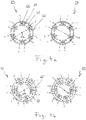
- a slot stator 59 is shown in the grooves 61 of a bobbin 63 of the slot stator 59 circumferentially equally distributed coils 65 are inserted such that the coil axes extend radially to the stator 67.
- the stator 59 comprises six identical coils 65. In principle, however, the stator 59 may also have any other number of coils 65. In the illustrated embodiment, in each case three coils 65 arranged next to one another are operated in the same current direction, ie in each case three adjacent coils 65 have the same magnetic orientation in the radial direction. In sum, the stator 59 thus has a positive magnetic pole extending over a semicircle and a negative magnetic pole extending over a semicircle.
- the magnetic driver consists in Fig. 4a from a single permanent magnet 57, which aligns in a known manner in the outer two-pole magnetic field of the stator 59, in particular to the respective centrally arranged coil 65 of each three operated in the same direction of current coils 65 shows.
- a short-circuit ring can be used.
- the coils 65 are driven so that the separation plane between the semicircular positive magnetic pole and the semi-circular negative magnetic pole of the stator 59 moves in a clockwise or counterclockwise direction.
- the coils 65 of the stator 59 can also be arranged such that the coil axes each extend tangentially to the stator axis 67, as in Fig. 4b is shown.
- the stator 59 comprises a common ring core 69, on which the coils 65 are wound.
- the Coils 65 are arranged distributed uniformly in the circumferential direction, in turn, each three coils 65 are energized in the same direction.
- the stator 59 then forms two semi-annular electromagnets which are parallel to each other, whereby a total of a two-pole stator 59 is formed in the context of the present application. In the two places where the same poles meet, it comes to field displacement.
- the field lines exit the ring 69 radially and exert a force on the inner rotor 31. Again, the direction of the magnetic field is changed by an alternating energization of the coils such that a total of a rotating magnetic field is formed.
- a foam sensor not shown in the figures, is provided, which may in principle be arranged at or below or above the rotor 31 in the expansion vessel 27.
- the presence of foam per se can be detected by a foam sensor arranged above the rotor 31 and, in response to a corresponding signal from the foam sensor, the rotor 31 can be automatically started independently of the foam density.
- the density of the foam can be detected and the rotor 31 can be put into operation only when a specific limit value is exceeded.
Landscapes
- Chemical & Material Sciences (AREA)
- Chemical Kinetics & Catalysis (AREA)
- Dispersion Chemistry (AREA)
- Vaporization, Distillation, Condensation, Sublimation, And Cold Traps (AREA)
Claims (15)
- Évaporateur rotatif (11) pour la distillation sous vide d'un liquide, comprenant un bain chauffant (17), une ampoule de vaporisation (15) susceptible d'être plongée dans le bain chauffant (17) et un refroidisseur (21), qui est branché à la suite de l'ampoule de vaporisation (15) et qui est relié à celle-ci via une amenée de vapeur (29),
caractérisé en ce qu'un rotor (31) comportant un destructeur de mousse mécanique (33) est prévu à l'intérieur de l'amenée de vapeur (29). - Évaporateur rotatif selon la revendication 1,
caractérisé en ce que le rotor (31) est entraîné sans contact par un moyen d'entraînement (59) agencé à l'extérieur de l'amenée de vapeur (29), ou par une batterie réalisée de manière intégrale avec le rotor (31). - Évaporateur rotatif selon la revendication 1 ou 2,
caractérisé en ce que l'entraînement du rotor (31) a lieu par voie électromagnétique au moyen d'un stator (59) qui est agencé à l'extérieur de l'amenée de vapeur (29). - Évaporateur rotatif selon la revendication 3,
caractérisé en ce que le stator (59) inclut plusieurs bobines agencées de façon répartie en direction périphérique, qui sont pilotées de telle façon que cela produit un champ magnétique rotatif, et/ou en ce que le stator (59) comprend plusieurs pôles magnétiques agencés de façon répartie en direction périphérique. - Évaporateur rotatif selon l'une des revendications précédentes, caractérisé en ce que le rotor (31) inclut un nombre pair d'aimants permanents (57) agencés de façon répartie en direction périphérique, ou une bague de court-circuit.
- Évaporateur rotatif selon l'une des revendications 3 à 5,
caractérisé en ce que le stator (59) inclut plusieurs bobines (65) agencées de façon répartie en direction périphérique, avec des axes orientés radialement ou tangentiellement. - Évaporateur rotatif selon l'une des revendications précédentes, caractérisé en ce que l'amenée de vapeur (29) comprend un emplacement de mise en place pour le rotor (31), emplacement auquel deux tronçons d'amenée de vapeur (45, 47) séparés l'un de l'autre de l'amenée de vapeur (29) sont reliés de façon hermétiquement étanche et détachable l'un avec l'autre.
- Évaporateur rotatif selon la revendication 7,
caractérisé en ce qu'un écartement est formé entre les deux tronçons d'amenée de vapeur (45, 47), ledit écartement étant comblé par une pièce d'insert (49). - Évaporateur rotatif selon l'une des revendications précédentes, caractérisé en ce qu'il est prévu un dispositif de soutien (37) avec un palier pour le rotor (31).
- Évaporateur rotatif selon la revendication 9,
caractérisé en ce que le dispositif de soutien (37) s'appuie contre les parois intérieures de l'amenée de vapeur (29) ou est réalisé de manière intégrale avec une pièce d'insert (49). - Évaporateur rotatif selon la revendication 9 ou 10,
caractérisé en ce que le dispositif de soutien inclut plusieurs barrettes (39) s'étendant radialement et agencées de façon répartie en direction périphérique de l'amenée de vapeur (29), ou bien un tronçon en entonnoir (71) branché avant le rotor (31) et qui va en se rétrécissant dans la direction d'écoulement de la vapeur. - Évaporateur rotatif selon l'une des revendications précédentes, caractérisé en ce que le destructeur de mousse mécanique (33) est réalisé sous forme d'une centrifugeuse à mousse ou d'un organe d'agitation.
- Évaporateur rotatif selon l'une des revendications précédentes, caractérisé en ce que l'amenée de vapeur (29) comprend un vase d'expansion (27), et le rotor (31) est agencé à l'intérieur du vase d'expansion (27).
- Évaporateur rotatif selon l'une des revendications précédentes, caractérisé en ce qu'il est prévu un détecteur de mousse, agencé à l'intérieur de l'amenée de vapeur (29), pour la détection de la mousse présente dans l'amenée de vapeur (29).
- Évaporateur rotatif selon la revendication 14,
caractérisé en ce que l'évaporateur rotatif (11) est conçu pour mettre le rotor (31) automatiquement en rotation lorsque le capteur de mousse détecte que la mousse présente dans l'amenée de vapeur (29) dépasse une mesure prédéterminée.
Applications Claiming Priority (2)
| Application Number | Priority Date | Filing Date | Title |
|---|---|---|---|
| DE102013204459.3A DE102013204459A1 (de) | 2013-03-14 | 2013-03-14 | Rotationsverdampfer |
| PCT/EP2014/054413 WO2014139866A1 (fr) | 2013-03-14 | 2014-03-07 | Évaporateur rotatif |
Publications (2)
| Publication Number | Publication Date |
|---|---|
| EP2950901A1 EP2950901A1 (fr) | 2015-12-09 |
| EP2950901B1 true EP2950901B1 (fr) | 2017-01-11 |
Family
ID=50239624
Family Applications (1)
| Application Number | Title | Priority Date | Filing Date |
|---|---|---|---|
| EP14708862.9A Not-in-force EP2950901B1 (fr) | 2013-03-14 | 2014-03-07 | Evaporateur rotatif |
Country Status (4)
| Country | Link |
|---|---|
| US (1) | US9981202B2 (fr) |
| EP (1) | EP2950901B1 (fr) |
| DE (1) | DE102013204459A1 (fr) |
| WO (1) | WO2014139866A1 (fr) |
Families Citing this family (10)
| Publication number | Priority date | Publication date | Assignee | Title |
|---|---|---|---|---|
| CN108236356B (zh) * | 2016-12-26 | 2024-01-12 | 佛山市顺德区美的电热电器制造有限公司 | 蒸汽阀和电饭煲 |
| DE202017003355U1 (de) | 2017-06-27 | 2017-07-24 | Heidolph Instruments GmbH & Co. KG | Laborgerät zum Verdampfen eines Stoffes |
| CN107551589A (zh) * | 2017-10-24 | 2018-01-09 | 湖州展舒生物科技有限公司 | 旋转蒸发器 |
| DE102018111790A1 (de) * | 2018-05-16 | 2019-11-21 | Anton Paar Provetec Gmbh | Stopfen für Automatische Destillationsmessungen |
| CN112044109A (zh) * | 2020-08-28 | 2020-12-08 | 中检集团南方测试股份有限公司 | 一体化智能蒸馏仪 |
| DE202021100897U1 (de) | 2021-02-23 | 2022-05-30 | Hans Heidolph GmbH | Magnetrührer mit Hubtisch |
| CN113102704A (zh) * | 2021-04-12 | 2021-07-13 | 郭之珩 | 一种电磁搅拌装置及电磁搅拌加工方法 |
| CN113368919B (zh) * | 2021-05-24 | 2022-06-24 | 湛江市霞山区正海生物科技有限公司 | 一种生物样品处理用旋转蒸发仪及其使用方法 |
| KR102322062B1 (ko) * | 2021-06-15 | 2021-11-04 | 주식회사 케이오씨바이오텍 | 외장형 거품센서가 구비된 회전증발기 |
| CN221451734U (zh) * | 2024-01-12 | 2024-08-02 | 鹏辰新材料科技股份有限公司 | 一种芳烃溶剂加工用旋转蒸发器 |
Family Cites Families (14)
| Publication number | Priority date | Publication date | Assignee | Title |
|---|---|---|---|---|
| GB773742A (en) * | 1954-07-19 | 1957-05-01 | Luwa Ag | A thin-layer evaporator with high-speed agitating means |
| US3252502A (en) | 1962-01-19 | 1966-05-24 | Allied Chem | Centrifugal wiped film evaporation process for viscous materials |
| CH412800A (de) | 1964-06-17 | 1966-05-15 | Buechi Glasapparatefabrik W | Rotationsverdampfer, insbesondere für Laboratoriumszwecke |
| DE1519556A1 (de) * | 1964-06-18 | 1970-03-05 | Buechi Walter | Rotationsverdampfer |
| DD109154A3 (fr) * | 1972-12-27 | 1974-10-20 | ||
| DE3008589A1 (de) | 1980-03-06 | 1981-09-10 | Bayer Ag, 5090 Leverkusen | Mechanischer schaumzerstoerer und verfahren zur mechanischen schaumzerstoerung |
| DE3526644C3 (de) * | 1985-07-25 | 1996-09-26 | Bela Medvey | Rotationsverdampfer |
| DD256829A1 (de) * | 1986-12-31 | 1988-05-25 | Rudisleben Chemieanlagenbau | Bruedenabscheider fuer einen rotationsduennschichtverdampfer |
| US4790911A (en) * | 1987-03-10 | 1988-12-13 | Martin Parkinson | Solvent evaporator |
| DK174109B1 (da) | 1992-10-05 | 2002-06-24 | Ohm Electric Co Ltd | Fremgangsmåde samt anordning til rensning af damp for dråber samt anvendelse af en sådan anordning |
| DE9315698U1 (de) * | 1993-10-14 | 1993-12-23 | BÜCHI LABORATORIUMS-TECHNIK AG, Flawil | Verdampfer-Kolben für einen Rotationsverdampfer |
| DE10114434B4 (de) | 2001-03-23 | 2005-04-07 | Hans-Georg Genser | Rotationsverdampfer mit prozeßabhängiger Drehzahlregelung |
| DE10226478B4 (de) * | 2001-07-05 | 2006-10-05 | Hans Georg Genser | Rotationsverdampfung mit variabler Dosierung |
| WO2011053942A1 (fr) * | 2009-11-02 | 2011-05-05 | Artisan Industries Inc. | Évaporateur à film mince raclé vertical |
-
2013
- 2013-03-14 DE DE102013204459.3A patent/DE102013204459A1/de not_active Withdrawn
-
2014
- 2014-03-07 US US14/774,965 patent/US9981202B2/en active Active
- 2014-03-07 WO PCT/EP2014/054413 patent/WO2014139866A1/fr not_active Ceased
- 2014-03-07 EP EP14708862.9A patent/EP2950901B1/fr not_active Not-in-force
Non-Patent Citations (1)
| Title |
|---|
| None * |
Also Published As
| Publication number | Publication date |
|---|---|
| US9981202B2 (en) | 2018-05-29 |
| US20160136539A1 (en) | 2016-05-19 |
| EP2950901A1 (fr) | 2015-12-09 |
| DE102013204459A1 (de) | 2014-09-18 |
| WO2014139866A1 (fr) | 2014-09-18 |
Similar Documents
| Publication | Publication Date | Title |
|---|---|---|
| EP2950901B1 (fr) | Evaporateur rotatif | |
| EP2453555B1 (fr) | Groupe motopompe | |
| EP0179824B1 (fr) | Dispositif pour agiter ou pomper | |
| EP1110298B1 (fr) | Machine electrique a aimants permanents | |
| EP1281007B1 (fr) | Machine, notamment pompe a vide, dotee de paliers magnetiques | |
| EP0979356B1 (fr) | Dispositif pour refroidir exterieurement un moteur d'entrainement electrique d'un ensemble pompe centrifuge | |
| EP3570415A1 (fr) | Entraînement rotatif électromagnétique et dispositif de rotation | |
| AT513498B1 (de) | Vorrichtung und Verfahren zur magnetischen Axiallagerung eines Rotors | |
| EP2390510B1 (fr) | Pompe à vide | |
| EP3072219A1 (fr) | Machine électrique comprenant un châssis et une enveloppe | |
| DE102015001313A1 (de) | Elektromaschine, insbesondere LSPM | |
| EP2607731B1 (fr) | Palier radial magnétique avec rotor à tôles en étoile | |
| DE112010002615B4 (de) | Induktionsheizwalzenvorrichtung | |
| DE3415236C2 (de) | Verfahren und Vorrichtung zum Betreiben eines Abtriebsdestillators | |
| DE1432769A1 (de) | Vakuumzentrifuge | |
| DE112016007469T5 (de) | Kernlose rotierende elektrische Maschine zum Betreiben mit Überlast, Antriebsverfahren für diese und diese beinhaltendes Antriebssystem | |
| EP2112755B1 (fr) | Moteur linéaire | |
| WO2015117811A2 (fr) | Dispositif pour surveiller l'espace radial entre le rotor et le stator de machines électriques | |
| DE2315786A1 (de) | Verfahren zum pumpen fluessiger metalle durch mitreissewirkung und pumpe zur durchfuehrung dieses verfahrens | |
| DE2138752C3 (de) | Flüssigkeitsgekühlte elektrische Maschine mit einem auf einer Hohlwelle angeordneten Läufer | |
| WO2013007669A1 (fr) | Palier à unité de production d'énergie | |
| DE102006043343A1 (de) | Dynamoelektrische Vorrichtung | |
| EP3108057B1 (fr) | Dispositif destiné à la préparation de substances | |
| DE102014212035A1 (de) | Elektrische Maschine | |
| DE102019101778B4 (de) | Motor, Rotor-Stator-Anordnung und Verwendung zum Betreiben eines Motors |
Legal Events
| Date | Code | Title | Description |
|---|---|---|---|
| PUAI | Public reference made under article 153(3) epc to a published international application that has entered the european phase |
Free format text: ORIGINAL CODE: 0009012 |
|
| 17P | Request for examination filed |
Effective date: 20150904 |
|
| AK | Designated contracting states |
Kind code of ref document: A1 Designated state(s): AL AT BE BG CH CY CZ DE DK EE ES FI FR GB GR HR HU IE IS IT LI LT LU LV MC MK MT NL NO PL PT RO RS SE SI SK SM TR |
|
| AX | Request for extension of the european patent |
Extension state: BA ME |
|
| DAX | Request for extension of the european patent (deleted) | ||
| REG | Reference to a national code |
Ref country code: DE Ref legal event code: R079 Ref document number: 502014002490 Country of ref document: DE Free format text: PREVIOUS MAIN CLASS: B01B0001020000 Ipc: B01D0003020000 |
|
| GRAP | Despatch of communication of intention to grant a patent |
Free format text: ORIGINAL CODE: EPIDOSNIGR1 |
|
| RIC1 | Information provided on ipc code assigned before grant |
Ipc: B01D 3/02 20060101AFI20160706BHEP Ipc: B01D 1/22 20060101ALI20160706BHEP Ipc: B01D 3/08 20060101ALI20160706BHEP Ipc: B01D 19/02 20060101ALI20160706BHEP Ipc: B01B 1/02 20060101ALI20160706BHEP |
|
| INTG | Intention to grant announced |
Effective date: 20160722 |
|
| STAA | Information on the status of an ep patent application or granted ep patent |
Free format text: STATUS: GRANT OF PATENT IS INTENDED |
|
| GRAS | Grant fee paid |
Free format text: ORIGINAL CODE: EPIDOSNIGR3 |
|
| GRAA | (expected) grant |
Free format text: ORIGINAL CODE: 0009210 |
|
| STAA | Information on the status of an ep patent application or granted ep patent |
Free format text: STATUS: THE PATENT HAS BEEN GRANTED |
|
| AK | Designated contracting states |
Kind code of ref document: B1 Designated state(s): AL AT BE BG CH CY CZ DE DK EE ES FI FR GB GR HR HU IE IS IT LI LT LU LV MC MK MT NL NO PL PT RO RS SE SI SK SM TR |
|
| REG | Reference to a national code |
Ref country code: GB Ref legal event code: FG4D Free format text: NOT ENGLISH |
|
| REG | Reference to a national code |
Ref country code: CH Ref legal event code: EP |
|
| REG | Reference to a national code |
Ref country code: AT Ref legal event code: REF Ref document number: 860730 Country of ref document: AT Kind code of ref document: T Effective date: 20170115 |
|
| REG | Reference to a national code |
Ref country code: IE Ref legal event code: FG4D Free format text: LANGUAGE OF EP DOCUMENT: GERMAN |
|
| REG | Reference to a national code |
Ref country code: DE Ref legal event code: R082 Ref document number: 502014002490 Country of ref document: DE Representative=s name: MANITZ FINSTERWALD PATENT- UND RECHTSANWALTSPA, DE Ref country code: DE Ref legal event code: R082 Ref document number: 502014002490 Country of ref document: DE Representative=s name: MANITZ, FINSTERWALD & PARTNER GBR, DE Ref country code: DE Ref legal event code: R081 Ref document number: 502014002490 Country of ref document: DE Owner name: HANS HEIDOLPH GMBH, DE Free format text: FORMER OWNER: HANS HEIDOLPH GMBH & CO. KG, 93309 KELHEIM, DE Ref country code: DE Ref legal event code: R082 Ref document number: 502014002490 Country of ref document: DE Representative=s name: MANITZ FINSTERWALD PATENTANWAELTE PARTMBB, DE |
|
| REG | Reference to a national code |
Ref country code: DE Ref legal event code: R096 Ref document number: 502014002490 Country of ref document: DE |
|
| REG | Reference to a national code |
Ref country code: CH Ref legal event code: NV Representative=s name: DR. GRAF AND PARTNER AG INTELLECTUAL PROPERTY, CH |
|
| REG | Reference to a national code |
Ref country code: FR Ref legal event code: PLFP Year of fee payment: 4 |
|
| REG | Reference to a national code |
Ref country code: LT Ref legal event code: MG4D |
|
| REG | Reference to a national code |
Ref country code: NL Ref legal event code: MP Effective date: 20170111 |
|
| PG25 | Lapsed in a contracting state [announced via postgrant information from national office to epo] |
Ref country code: NL Free format text: LAPSE BECAUSE OF FAILURE TO SUBMIT A TRANSLATION OF THE DESCRIPTION OR TO PAY THE FEE WITHIN THE PRESCRIBED TIME-LIMIT Effective date: 20170111 |
|
| PG25 | Lapsed in a contracting state [announced via postgrant information from national office to epo] |
Ref country code: GR Free format text: LAPSE BECAUSE OF FAILURE TO SUBMIT A TRANSLATION OF THE DESCRIPTION OR TO PAY THE FEE WITHIN THE PRESCRIBED TIME-LIMIT Effective date: 20170412 Ref country code: LT Free format text: LAPSE BECAUSE OF FAILURE TO SUBMIT A TRANSLATION OF THE DESCRIPTION OR TO PAY THE FEE WITHIN THE PRESCRIBED TIME-LIMIT Effective date: 20170111 Ref country code: HR Free format text: LAPSE BECAUSE OF FAILURE TO SUBMIT A TRANSLATION OF THE DESCRIPTION OR TO PAY THE FEE WITHIN THE PRESCRIBED TIME-LIMIT Effective date: 20170111 Ref country code: IS Free format text: LAPSE BECAUSE OF FAILURE TO SUBMIT A TRANSLATION OF THE DESCRIPTION OR TO PAY THE FEE WITHIN THE PRESCRIBED TIME-LIMIT Effective date: 20170511 Ref country code: NO Free format text: LAPSE BECAUSE OF FAILURE TO SUBMIT A TRANSLATION OF THE DESCRIPTION OR TO PAY THE FEE WITHIN THE PRESCRIBED TIME-LIMIT Effective date: 20170411 Ref country code: FI Free format text: LAPSE BECAUSE OF FAILURE TO SUBMIT A TRANSLATION OF THE DESCRIPTION OR TO PAY THE FEE WITHIN THE PRESCRIBED TIME-LIMIT Effective date: 20170111 |
|
| PG25 | Lapsed in a contracting state [announced via postgrant information from national office to epo] |
Ref country code: PT Free format text: LAPSE BECAUSE OF FAILURE TO SUBMIT A TRANSLATION OF THE DESCRIPTION OR TO PAY THE FEE WITHIN THE PRESCRIBED TIME-LIMIT Effective date: 20170511 Ref country code: RS Free format text: LAPSE BECAUSE OF FAILURE TO SUBMIT A TRANSLATION OF THE DESCRIPTION OR TO PAY THE FEE WITHIN THE PRESCRIBED TIME-LIMIT Effective date: 20170111 Ref country code: LV Free format text: LAPSE BECAUSE OF FAILURE TO SUBMIT A TRANSLATION OF THE DESCRIPTION OR TO PAY THE FEE WITHIN THE PRESCRIBED TIME-LIMIT Effective date: 20170111 Ref country code: BG Free format text: LAPSE BECAUSE OF FAILURE TO SUBMIT A TRANSLATION OF THE DESCRIPTION OR TO PAY THE FEE WITHIN THE PRESCRIBED TIME-LIMIT Effective date: 20170411 Ref country code: PL Free format text: LAPSE BECAUSE OF FAILURE TO SUBMIT A TRANSLATION OF THE DESCRIPTION OR TO PAY THE FEE WITHIN THE PRESCRIBED TIME-LIMIT Effective date: 20170111 Ref country code: SE Free format text: LAPSE BECAUSE OF FAILURE TO SUBMIT A TRANSLATION OF THE DESCRIPTION OR TO PAY THE FEE WITHIN THE PRESCRIBED TIME-LIMIT Effective date: 20170111 Ref country code: ES Free format text: LAPSE BECAUSE OF FAILURE TO SUBMIT A TRANSLATION OF THE DESCRIPTION OR TO PAY THE FEE WITHIN THE PRESCRIBED TIME-LIMIT Effective date: 20170111 |
|
| REG | Reference to a national code |
Ref country code: DE Ref legal event code: R097 Ref document number: 502014002490 Country of ref document: DE |
|
| PG25 | Lapsed in a contracting state [announced via postgrant information from national office to epo] |
Ref country code: EE Free format text: LAPSE BECAUSE OF FAILURE TO SUBMIT A TRANSLATION OF THE DESCRIPTION OR TO PAY THE FEE WITHIN THE PRESCRIBED TIME-LIMIT Effective date: 20170111 Ref country code: RO Free format text: LAPSE BECAUSE OF FAILURE TO SUBMIT A TRANSLATION OF THE DESCRIPTION OR TO PAY THE FEE WITHIN THE PRESCRIBED TIME-LIMIT Effective date: 20170111 Ref country code: SK Free format text: LAPSE BECAUSE OF FAILURE TO SUBMIT A TRANSLATION OF THE DESCRIPTION OR TO PAY THE FEE WITHIN THE PRESCRIBED TIME-LIMIT Effective date: 20170111 Ref country code: CZ Free format text: LAPSE BECAUSE OF FAILURE TO SUBMIT A TRANSLATION OF THE DESCRIPTION OR TO PAY THE FEE WITHIN THE PRESCRIBED TIME-LIMIT Effective date: 20170111 |
|
| PLBE | No opposition filed within time limit |
Free format text: ORIGINAL CODE: 0009261 |
|
| STAA | Information on the status of an ep patent application or granted ep patent |
Free format text: STATUS: NO OPPOSITION FILED WITHIN TIME LIMIT |
|
| RAP2 | Party data changed (patent owner data changed or rights of a patent transferred) |
Owner name: HANS HEIDOLPH GMBH |
|
| PG25 | Lapsed in a contracting state [announced via postgrant information from national office to epo] |
Ref country code: DK Free format text: LAPSE BECAUSE OF FAILURE TO SUBMIT A TRANSLATION OF THE DESCRIPTION OR TO PAY THE FEE WITHIN THE PRESCRIBED TIME-LIMIT Effective date: 20170111 Ref country code: MC Free format text: LAPSE BECAUSE OF FAILURE TO SUBMIT A TRANSLATION OF THE DESCRIPTION OR TO PAY THE FEE WITHIN THE PRESCRIBED TIME-LIMIT Effective date: 20170111 Ref country code: SM Free format text: LAPSE BECAUSE OF FAILURE TO SUBMIT A TRANSLATION OF THE DESCRIPTION OR TO PAY THE FEE WITHIN THE PRESCRIBED TIME-LIMIT Effective date: 20170111 |
|
| 26N | No opposition filed |
Effective date: 20171012 |
|
| REG | Reference to a national code |
Ref country code: IE Ref legal event code: MM4A |
|
| PG25 | Lapsed in a contracting state [announced via postgrant information from national office to epo] |
Ref country code: LU Free format text: LAPSE BECAUSE OF NON-PAYMENT OF DUE FEES Effective date: 20170307 |
|
| PG25 | Lapsed in a contracting state [announced via postgrant information from national office to epo] |
Ref country code: SI Free format text: LAPSE BECAUSE OF FAILURE TO SUBMIT A TRANSLATION OF THE DESCRIPTION OR TO PAY THE FEE WITHIN THE PRESCRIBED TIME-LIMIT Effective date: 20170111 Ref country code: IE Free format text: LAPSE BECAUSE OF NON-PAYMENT OF DUE FEES Effective date: 20170307 |
|
| REG | Reference to a national code |
Ref country code: BE Ref legal event code: MM Effective date: 20170331 |
|
| REG | Reference to a national code |
Ref country code: FR Ref legal event code: PLFP Year of fee payment: 5 |
|
| PG25 | Lapsed in a contracting state [announced via postgrant information from national office to epo] |
Ref country code: BE Free format text: LAPSE BECAUSE OF NON-PAYMENT OF DUE FEES Effective date: 20170331 |
|
| PG25 | Lapsed in a contracting state [announced via postgrant information from national office to epo] |
Ref country code: MT Free format text: LAPSE BECAUSE OF FAILURE TO SUBMIT A TRANSLATION OF THE DESCRIPTION OR TO PAY THE FEE WITHIN THE PRESCRIBED TIME-LIMIT Effective date: 20170111 |
|
| PG25 | Lapsed in a contracting state [announced via postgrant information from national office to epo] |
Ref country code: HU Free format text: LAPSE BECAUSE OF FAILURE TO SUBMIT A TRANSLATION OF THE DESCRIPTION OR TO PAY THE FEE WITHIN THE PRESCRIBED TIME-LIMIT; INVALID AB INITIO Effective date: 20140307 |
|
| PG25 | Lapsed in a contracting state [announced via postgrant information from national office to epo] |
Ref country code: CY Free format text: LAPSE BECAUSE OF FAILURE TO SUBMIT A TRANSLATION OF THE DESCRIPTION OR TO PAY THE FEE WITHIN THE PRESCRIBED TIME-LIMIT Effective date: 20170111 |
|
| PGFP | Annual fee paid to national office [announced via postgrant information from national office to epo] |
Ref country code: IT Payment date: 20190829 Year of fee payment: 6 Ref country code: DE Payment date: 20190830 Year of fee payment: 6 Ref country code: FR Payment date: 20190822 Year of fee payment: 6 |
|
| PG25 | Lapsed in a contracting state [announced via postgrant information from national office to epo] |
Ref country code: MK Free format text: LAPSE BECAUSE OF FAILURE TO SUBMIT A TRANSLATION OF THE DESCRIPTION OR TO PAY THE FEE WITHIN THE PRESCRIBED TIME-LIMIT Effective date: 20170111 |
|
| PGFP | Annual fee paid to national office [announced via postgrant information from national office to epo] |
Ref country code: GB Payment date: 20190821 Year of fee payment: 6 |
|
| PGFP | Annual fee paid to national office [announced via postgrant information from national office to epo] |
Ref country code: CH Payment date: 20190821 Year of fee payment: 6 |
|
| PG25 | Lapsed in a contracting state [announced via postgrant information from national office to epo] |
Ref country code: TR Free format text: LAPSE BECAUSE OF FAILURE TO SUBMIT A TRANSLATION OF THE DESCRIPTION OR TO PAY THE FEE WITHIN THE PRESCRIBED TIME-LIMIT Effective date: 20170111 |
|
| PG25 | Lapsed in a contracting state [announced via postgrant information from national office to epo] |
Ref country code: AL Free format text: LAPSE BECAUSE OF FAILURE TO SUBMIT A TRANSLATION OF THE DESCRIPTION OR TO PAY THE FEE WITHIN THE PRESCRIBED TIME-LIMIT Effective date: 20170111 |
|
| REG | Reference to a national code |
Ref country code: AT Ref legal event code: MM01 Ref document number: 860730 Country of ref document: AT Kind code of ref document: T Effective date: 20190307 |
|
| REG | Reference to a national code |
Ref country code: DE Ref legal event code: R119 Ref document number: 502014002490 Country of ref document: DE |
|
| REG | Reference to a national code |
Ref country code: CH Ref legal event code: PL |
|
| PG25 | Lapsed in a contracting state [announced via postgrant information from national office to epo] |
Ref country code: AT Free format text: LAPSE BECAUSE OF NON-PAYMENT OF DUE FEES Effective date: 20190307 |
|
| PG25 | Lapsed in a contracting state [announced via postgrant information from national office to epo] |
Ref country code: LI Free format text: LAPSE BECAUSE OF NON-PAYMENT OF DUE FEES Effective date: 20200331 Ref country code: FR Free format text: LAPSE BECAUSE OF NON-PAYMENT OF DUE FEES Effective date: 20200331 Ref country code: CH Free format text: LAPSE BECAUSE OF NON-PAYMENT OF DUE FEES Effective date: 20200331 Ref country code: DE Free format text: LAPSE BECAUSE OF NON-PAYMENT OF DUE FEES Effective date: 20201001 |
|
| GBPC | Gb: european patent ceased through non-payment of renewal fee |
Effective date: 20200307 |
|
| PG25 | Lapsed in a contracting state [announced via postgrant information from national office to epo] |
Ref country code: GB Free format text: LAPSE BECAUSE OF NON-PAYMENT OF DUE FEES Effective date: 20200307 |
|
| PG25 | Lapsed in a contracting state [announced via postgrant information from national office to epo] |
Ref country code: IT Free format text: LAPSE BECAUSE OF NON-PAYMENT OF DUE FEES Effective date: 20200307 |